

Page 1

FCC Statement
Notice:
The changes or modifications not expressly approved by the party responsible for compliance
could void the user’s authority to operate the equipment.
This device complies with part 15 of the FCC Rules. Operation is subject to the following two
conditions: (1) This device may not cause harmful interference, and (2) this device must
accept any interference received, including interference that may cause undesired operation.
IMPORTANT NOTE:
To comply with the FCC RF exposure compliance requirements, no change to the antenna or
the device is permitted. Any change to the antenna or the device could result in the device
exceeding the RF exposure requirements and void user’s authority to operate the device.
FCC INFORMATION
The equipment has been tested and found to comply with the limits for a Class B
Digital Device, pursuant to part 15 of the FCC Rules. These limits are designed to provide
reasonable protection against harmful interference in a residential installation. This
equipment generates, uses and can radiate radio frequency energy and, if not installed and
used in accordance with the instruction, may cause harmful interference to radio
communication. However, there is no grantee that interference will not occur in a particular
installation. If this equipment dose cause harmful interference to radio or television
reception, which can be determined by turning the equipment off and on , the user is
encouraged to try to correct the interference by one or more of the following measures:
--Reorient or relocate the receiving antenna.
--Increase the separation between the equipment and receiver.
--Connect the equipment into an outlet on a circuit different from that to which the receiver
is connected.
--Consult the dealer or an experienced radio/TV technician for help.
Page 2
WIRELESS
TOUR GUIDE
SYSTEM
TG-98R/98T
TG-98RA/98TA
TG-98T/TA
TG-98R/RA
WIRELESS
TOUR GUIDE SYSTEM
59516-007
1856
1 2
TG-64CH36 / TG-64CH18 / TG-64CH2
Number of charging slot
Power requirement
LED Indicator
Dimensions(mm)
TG-64CH18 : 18(receiver or transmitter)
TG-64CH2 : 2 (receiver or transmitter)
TG-64CH36 : Input : AC100~240V, 2.8A ,max
Power connected: Flash Green
Charging : Green
TG-64CH36 : 561(W)* 399.77(D)* 230(H)
TG-64CH18 : 361.4(W)* 422(D)* 189(H)
TG-64CH2 : 85(W)* 75(D)* 41(H)
TG-98R/TG-98RA
TG-98T/TG-98TA
Full Charged:Turn o
Dimension(mm)
Battery
Battery life
Microphone input
connector
Audio Frequency Response
Spurious Emissions
Controls
Frequency Deviation
Stability
RF Outputs
Carrier Frequency Range
Frequency Preparation
Internal Microphone
Carrier Frequency Range
Controls
Audio Frequency Response
Output connector
Battery life
Battery
Dimension(mm)
Frequency Preparation
PLL Synthesized Control
470MHz~960MHz
Channel Power On/O,
Channel selection Volume control,
Group selection, Limiter, Auto OFF,
Low Batt Warning, Key Lock, Mute,
40~18,000Hz
1/8” Dummy stereo Phone Jack
10 hours typical
Rechargeable NIMH AA
(1.2V,2000mAh)
62mm(W)* 20mm(D)* 97mm(H)
Omni-directional Condenser
Microphone
PLL Synthesized Control
470MHz~960MHz
10mW
±10kHz
±48kHz
Power On/O, Channel selection,
Volume control, Group selection,
RF Booster, Key Lock, Mute
<-50 dBC
40~18,000 Hz
1/8” Mono Phone Jack
10 hours typical
Rechargeable NIMH AA
(1.2V, 2000mAh)
62mm(W)* 20mm(D)* 97mm(H)
Output : DC 12V, 16A
TG-64CH18 : Input : AC100~240V, 1.6A ,max
TG-64CH2 : Input : 12~18VDC, 600mA
Output : DC 12V, 7A
TG-64CH36 : 36(receiver or transmitter)
Do not leave the devices in a place with high
temperature or high humidity.
TG-98 is designed on the base of the TG-10
successful experience plus JTS very recent
innovative ideas
Use rechargeable AA battery
TG-98 is a wide band tour guide system with 36
MHz bandwidth
Preset 6 groups each of up to 23 channels.
Transmission power selectable
Built in limit switch of audio output
Line In at Transmitter and Line Out at Receiver,
ready for video camera
Built in speaker at Receiver and microphone at
Transmitter
Adjustable Power Auto Off at Receiver to save
battery power
Low battery alarm
RF Strength gauge
Panel lock
Mute Function (Transmitter )
Compatible with stationary transmitter
TG-98GSTX and receiver TG-98GSRX
Important Caution
Feature
Keep the devices away from re and heat sources.
Please fully charge the battery 8 hours before
rst
operation, and recharge if no use for over
three months.
Page 3
WIRELESS TOUR GUIDE SYSTEM
TG-98R(A)/TG-98T(A)
TG-98R(A) / TG-98T(A)
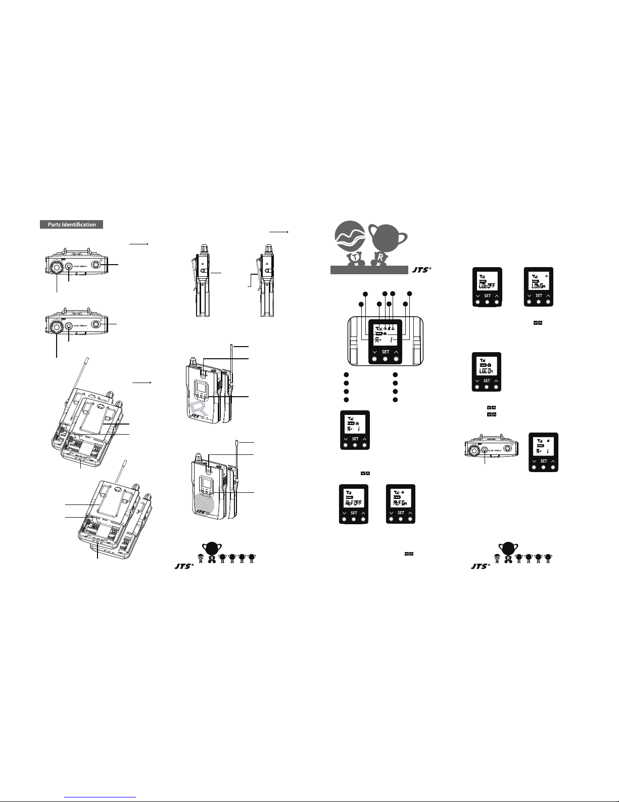
TG-98R(A)
Power/Mute Switch
and Status LED
3.5mm Microphone
Input Jack
Top Panel
Bottom Panel
TG-98T(A)
Volume Control
Power/Mute Switch
and Status LED
3.5mm
Dummy Stereo Earphone
Output Jack
TG-98R(A)
Volume Control
Belt Clip
Belt Clip
AF Limiter
RF Boost
Charge Connector
Charge Connector
98
3.5mm mono
Line Out
Left Side Panel
TG-98R(A) TG-98T(A)
3.5mm mono
Line In
Antenna
TG-98R/TG-98RA
Built-in Speaker
LCD Display
TG-98T/TG-98TA
LINE OUT
LINE IN
TG-98T(A)
3
4
WIRELESS TOUR GUIDE SYSTEM
TG-98R(A)/TG-98T(A)
Installation and Operation
1
1
2
3
4
5
6
7
8
2
3
4
5
678
Group
Battery Level
RF Signal Level
Auto Power Off
Mute
Low Battery Warning
Key Lock
Channel
2. Auto Power Off Function (Receiver Only)
a.Default Setting is OFF. Press to set ON.
b.Clock icon appears when the function is ON.
c.Press SET to save.
3. Low Battery Level Warning Function (Receiver Only)
a. Default Setting is OFF. Press to set ON.
b. Alarm icon appears when the function is ON.
c. Press SET to save.
4. Key Lock Functiont
a. Press at the same time till LOC ON appears.
b. Press at the same time to unlock.
5. Mute Functiont
a. Quick press the power button to turn on/cancel the
mute function (Long press to power on/off)
b. Speaker icon appears when the function is ON.
1. Long Press SET to Enter Function Setting
a. English letters for group / Numbers for channel
Press to select / Press SET to save.
Receiver auto power Off 30 minutes after the
transmitter is OFF
5
6
Power/Mute Switch
and Status LED
T
98
T
Antenna
Built-in Mic
LCD Display
Page 4
WIRELESS TOUR GUIDE SYSTEM
TG-98R(A)/TG-98T(A)
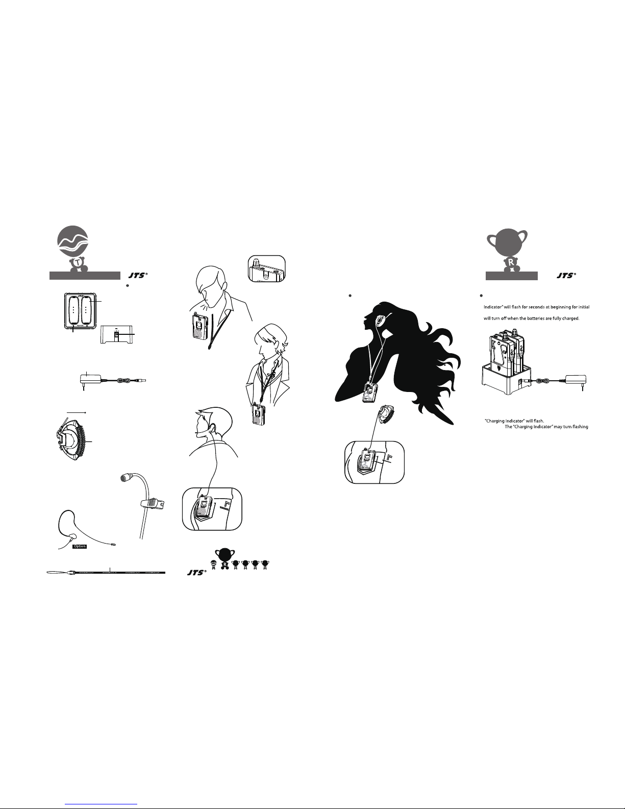
Charger Slot
DC input (12V)
Charging Indicator
Neck-Strap
Accessories
WM-10TG
Mono Earphone ( For TG-98R/RA)
Optional : CM-201S omnidirectional
Lavaliere Microphone
(For TG-98T/TA)
CM-801S omnidirectional
Earhook Microphone
(For TG-98T/TA)
Adaptor (100-240V input, 600mA 12V output)
12V 600mA
TG-98R/TG-98RA
Use the “Belt-Clip”
and the “Mono Earphone”
Plug the TG-98T/TG-98R (Charger Connector faces
down) into “Charger Slot” in TG-64CH2.The “Charging
testing, and then show green light when charging. It
Notice 1 : As soon as AC power is connected, the
Notice 2 :
for selt-testing during charging to protect batteries
from being damaged.
98
Wearing and Operating
TG-64CH2
Use the “Belt-Clip” and
the “external Microphone”
Use the “Neck-Strap”
and the
“external Microphone”
Earhook Microphone
CM-801S
Use the “Neck-Strap”
and the
“Built-in Microphone”
MIC
T
MIC
T
T
98
7 8 9 10
Charge Battery
Use the “Neck-Strap”
and the
“Mono Earphone”
 Loading...