

R -988KB
UHF PLL DUAL CHANNEL DIVERSITY RECEIVER
59508-095-02
2
No. 148, 9th Industry Road, Ta-Li Industrial
PROFESSIONAL CO., LTD.
Park,Taichung City, Taiwan, R.O.C.
Tel: 886-4-24938803 Fax: 886-4-24914890
E-mail: jts@jts.com.tw
www.jts.com.tw
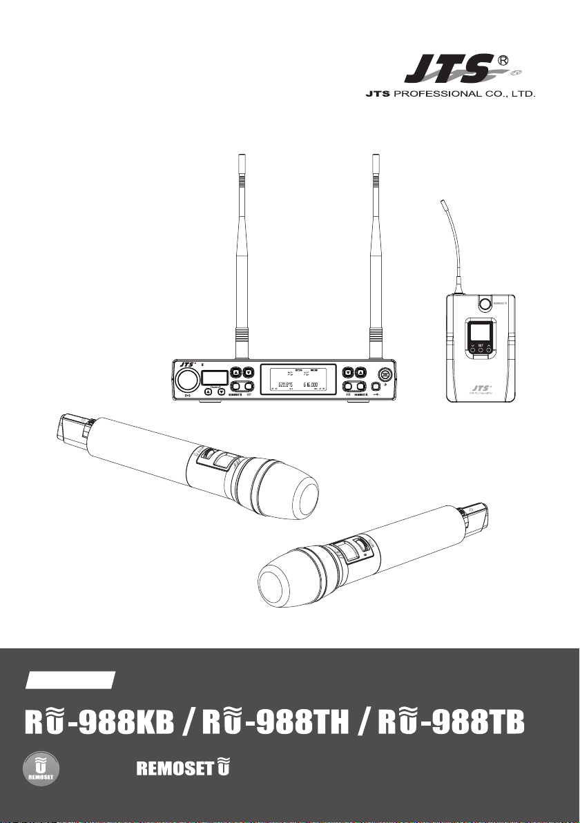
UHF PLL DUAL CHANNEL DIVERSITY RECEIVER
R -988KB
Instruction Manual
UHF PLL
With JTS Ultrasonic Synchronizing Technology
3

One year product warranty
Product Model
Customer
name
Address
Purchase date
Selling store
stamp
Be sure to put store stamp and ll in purchase date for the warranty to be
eective!
Warranty description
1. Be sure to put the warranty label indicating purchase date on the bottom of
equipment to ensure your interest in maintenance and service.
2. Product warranty, starting on the purchase date indicated on “warranty label”, will
last for one year; if the equipment does not have “warranty label”, the warranty
period is 15 months from the manufacturing date. If a microphone is broken but
not sent back with the equipment, the warranty period is 15 months from the
manufacturing date of the microphone.
3. Within the warranty period, if the equipment is broken under normal use as
instructed in manual, please contact the original selling store for repair.
4. When the product is returned for repair, to facilitate proper determination of
cause of malfunction and of whether repair fee is needed, please ship back the
equipment and microphone together.
5. Within the warranty period, our company provides repair service at no cost
except for the following conditions that parts and repair may be charged:
a.Damages due to natural disaster or irresistible outside forces.
b.Damages due to drop, water, moisture, corrosion, foreign objects, missing
components.
c.The warranty does not cover consumable parts. (such as microphone capsule,
ball grille etc.)
d.Those without “warranty label” on equipment or with “warranty label” being
damaged and failing to identify warranty period.
6. Please keep the warranty properly. No replacement will be made if the warranty
is missing.
Equipment
serial number
Contact
number
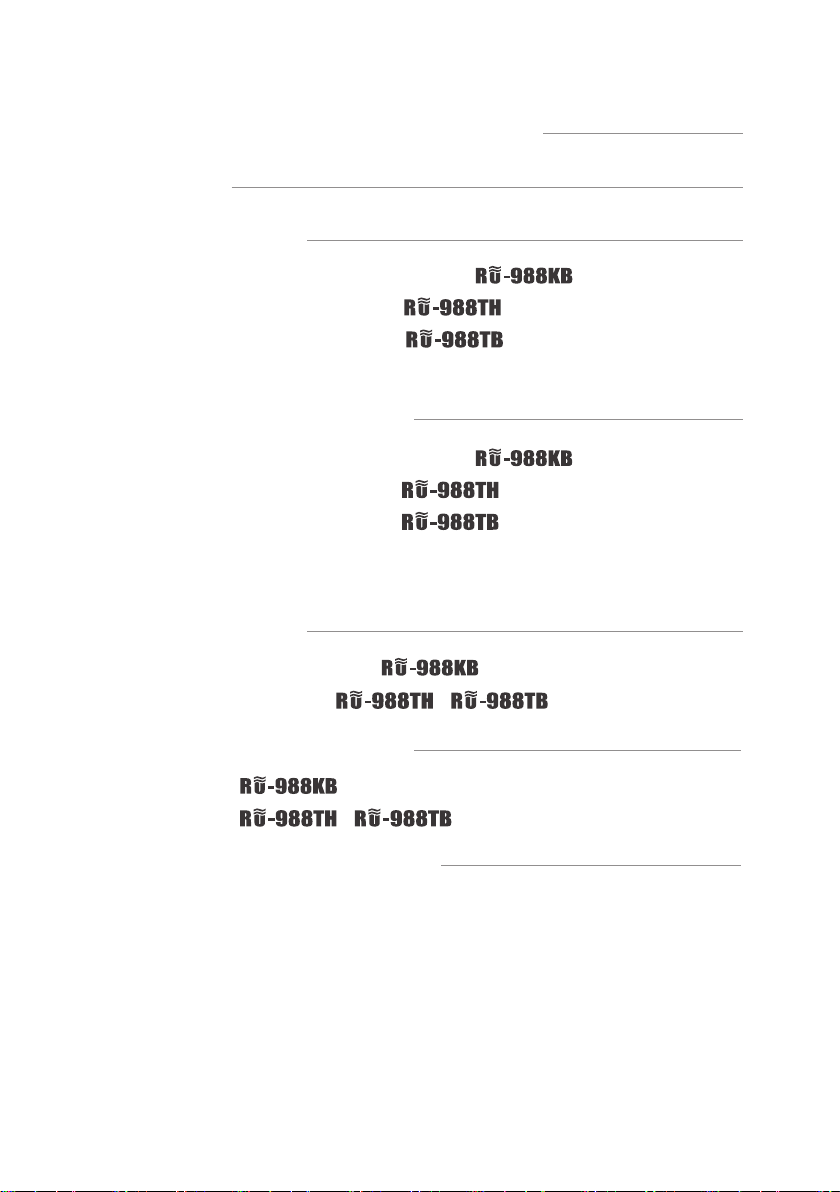
Table of Contents
1. Notes for system operations
2. Features
3. Specications
3-1 UHF PLL dual-channel diversity receiver //
3-2 UHF PLL hand-held transmitter //
3-3 UHF PLL body-pack transmitter //
3-4 Optional condenser microphone
4. Description of parts
4-1 UHF PLL dual-channel diversity receiver //
4-2 UHF PLL hand-held transmitter //
4-3 UHF PLL body-pack transmitter //
4-4 Accessories
4-5 Optional Condenser Microphone
5. Connecting
5-1 How to connect the receiver //
5-2 Transmitter installation // /
1
1
2
2
3
3
4
6
6
9
10
11
11
14
14
15
6. Instructions for use
6-1 How to use //
6-2 How to use // /
7. Notes for the product
16
16
20
23

1. Notes for system operations
• Before connecting the power, check that the power requirement shown
on the unit is the same as the power output on the adaptor supplied.
• Do not leave the unit at where the humidity and temperature are high.
• Dry your hands before operating the system.
• Keep the unit away from re and heat source.
• Turn the volume to minimum at both the mixer and amplier before
setting up the system.
2. Features
• Wide band of 36MHz, specially intended for exquisite KTV rooms and
classrooms.
• Preset 90 pairs of channels.
• One key sets two channels.
• Easy squelch adjustment from front panel.
• Both frequency and channel are adjustable.
1

3. Specications
3-1 UHF PLL dual-channel diversity receiver
Model
Frequency Oscillation
Mode
Carrier Frequency Range 470~960 MHz
Remoset Frequency Ultrasonic
Diversity Antenna diversity
Bandwidth 36MHz
Signal/Noise Ratio >105dB(A)
Total Harmonic Distortion
(Thd)
Receiving Sensitivity -95dBm,S/N>80dB
Image Rejection Ratio >80 dB
Frequency Response 50Hz~16KHz±2dB
Antenna Type 1/2
Antenna Booster Power DC12~15V/100mA
Function Display By LCD / LED
Group, channel, frequency, battery level, antenna A/B, muting
Contents Of Display
Control Functions
Audio Frequency Output
Level
Audio Frequency Output
Impedance
Muting Noise muting and tone code locking
Output Port
Power Supply 12~15V DC / 500mA
Dimension (Mm) 210mm (W) x 40mm (H) x 172mm (L)
level, AF indication, RF indication, channel scanning, output level
attenuation, volume indication
Power, group, channel, frequency, muting level, button lock,
volume, output attenuation (XLR), channel scan (on/o)
Ref:±22.5KHz Dev@1KHz Tone
XLR Jack:-4dBV(Line)、-24dBV(MIC)
Phase-locked loop (PLL)
<0.6%@1KHz
BNC detachable
λ
ψ6.3 Phone Jack
2 x balanced XLR jack
1 x unbalanced ϕ6.3 jack
600Ω
-10dBV
:
2
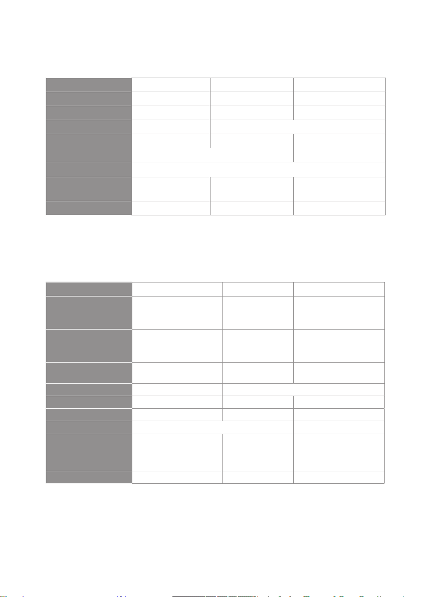
3-2 UHF PLL hand-held transmitter
Model
Frequency Oscillation Mode Phase-locked loop (PLL)
Carrier Wave Frequency Range 470~960 MHz
Remoset Frequency Ultrasonic
RF Power Output 10mW/50mW(as per local regulations)
RF Stability <±10KHz@Fc
Modulation Frequency Shift ±48KHz
Harmonic Radiation <-50dBc
Functions Mute, auto o, sensitivity adjustment, low power indication
Display By LCD+LED
Controls
Battery AA alkali battery or MiNH rechargeable battery x 2
Charging Yes
Dimension 51mm (W) x 269mm (H) x 26mm (L)
Power, mute, group, channel, frequency, sensitivity
adjustment, auto o, button lock
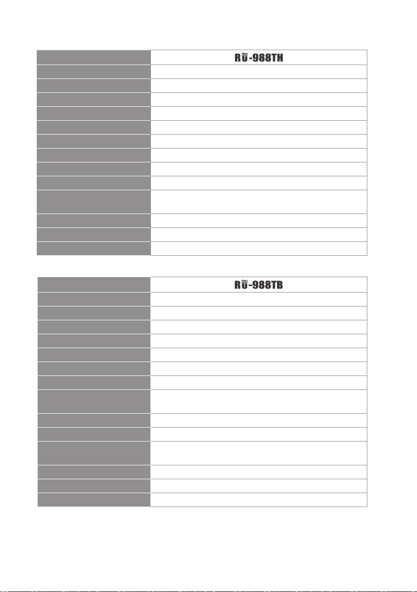
3-3 UHF PLL body-pack transmitter
Model
Frequency Oscillation Mode Phase-locked loop (PLL)
Carrier Wave Frequency Range 470~960MHz
Remoset Frequency Ultrasonic
RF Power Output 10mW/50mW(as per local regulations)
RF Stability <±10KHz@Fc
Modulation Frequency Shift ±48KHz
Harmonic Radiation <-50dBc
Functions
Display By LCD+LED
Input Port 4 pin Mini XLR
Controls
Battery AA alkali battery or MiNH rechargeable battery x 2
Charging Yes
Dimension 62mm (W) x 97mm (H) x 20mm (L)
Mute, auto o, input level attenuation, sensitivity
adjustment, low power indication
Power, mute, group, channel, frequency, sensitivity
adjustment, input level attenuation, auto o
3
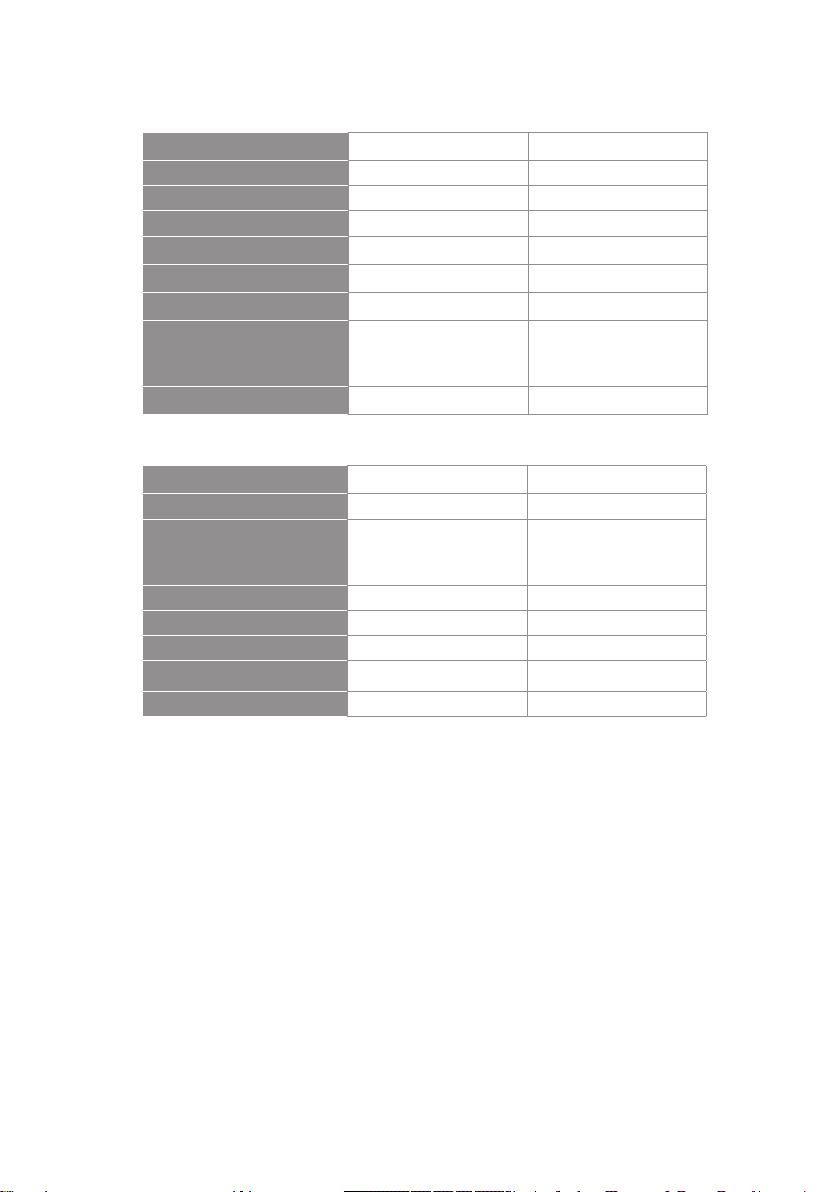
3-4 Optional condenser microphone
Lavaliere microphone
Model
Connector
Frequency Response
Polar Pattern
Sensitivity (at 1000Hz) -60 ± 3dB -60 ± 3dB -53 ± 3dB
Impedance
Max. SPL for 1% THD
Dimension (mm)
Net Weight 21.5g 20.7g 7g (cable not included)
CM-501 CM-201i CM-125i
4-pin mini XLR 4-pin mini 4-pin mini XLR
100~15,000 Hz XLR60~15,000 Hz 50~18,000 Hz
Cardioid Omni-directivity
2.2K Ω 4.4K Ω
130dB
Ø10.1mm (W) x
26.4mm (H)
Ø5mm (W) x
9mm (H)
Ø4mm (W) x
11mm (H)
Headset microphone
Model CM-214i CM-214Ui CM-214ULi
Connector
Option
Connector
Frequency Response
Polar Pattern Omni-directional Cardioid
Sensitivity (at 1000Hz) -60±3 dB -68±3 dB -65±3 dB
Impedance 1.8kΩ 680Ω 1.8kΩ
Max. SPL for 1% THD 130dB 120dB
Dimension(mm)
Net Weight 32.9g 38.4g 18g (cable excluded)
801C4
(4P Mini XLR)
801C3 (3P Mini XLR)
801CS (3.5 stereo plug)
801CR
60~15,000 Hz 30~18,000 Hz 100 ~ 18,000Hz
125mm(W) x
134mm(H)x
157mm(D)
4P Mini XLR
205mm(W)x
134mm(H)x
157mm(D)
801C3 (3P Mini XLR)
801C4 (4P Mini XLR)
801CS (3.5 stereo plug)
801CR
125mm(W)x
134mm(H)x
157mm(D)
4
Model CM-235i CX-504
Connector 801C4 (4P Mini XLR ) 4P Mini XLR
Frequency Response 50~18,000 Hz 30~18,000 Hz
Polar Pattern Omni-directional Cardioid
Sensitivity (at 1000Hz)
Impedance
Max. SPL for 1% THD
Dimension(mm)
Net Weight
-53 ± 3dB
1.8kΩ 680Ω
130dB
155mm(W)x
134mm(H)x
157mm(D)
17g (cable excluded) 56.3g
-68 ± 3dB
130dB
285mm(W)x
55mm(H)x
111.3mm(D)
Ear-hook microphone
Model No CM-801 / CM-804i CM-8015 / CM-825i
Connector 801C4 (4P Mini XLR) 801C4 (4P Mini XLR)
801C3 (3P Mini XLR)
Option Connector
Frequency Response 60~15,000 Hz 50~18,000 Hz
Polar Pattern Omni-directional Omni-directional
Sensitivity (at 1000Hz) -64±3 dB -53±3 dB
Impedance
Max. SPL for 1% THD 130dB 130dB
801CS (3.5 stereo plug)
801CR
1.8kΩ 1.8kΩ
801C3 (3P Mini XLR)
801CS (3.5 stereo plug)
801CR
5

4. Description of parts
4-1 UHF PLL dual-channel diversity receiver //
Front panel Rear panel
3 3
10
5
8
6
1
Power switch:short press to start up, long press for two seconds to shut down.
2
SET key:Keys to set the functions. Long press for two seconds to enter the setting
4
2
9
JTS PROFESSIONAL CO., LTD.
No. 148, 9th Industry Road,
Ta-Li Industrial Park,
Taichung City, Taiwan, R.O.C.
1
8
7
2
11 12 1113 14 15
mode, press the “SET” key again to enter the setting of dierent functions.
3
▲/▼Keys to select functions: In the setting mode, press the ▲/▼ key to adjust
function parameters. In the non-setting mode, press the ▲/▼ key to set the output
volume.
4
LCD Screen
5
3 Digits Seven-Segment Display: Display current preset channels *01~*90, and the
group channels *91~*96.
6
Default preset channel selection key:For users to quickly set the preset channels.
7
Lock key:long press the “LOCK” key for two seconds to lock the function of key. Avoid
accidentally touch the setting.
8
button: For users to synchronize the setting set in the receiver with that
of the transmitter.
6

9
Power, indicator light: In the normal state, it serves as the power indicator light (bright red). The display will show the following when carrying
out channel matching: , when transmitting data, the indicator light will blink fast (green light); once the synchronization is done, it
will stop blinking. If synchronization fails after channel matching is carried out for some time, the blinking rate of indicator light will slow down.
10
Ultrasonic transmitter unit:Transmit the content of setting as digital
data through the ultrasonic transmitter.
11
BNC Antenna base: Connect 50Ω BNC antenna and provide DC12 ~ 15V
/ 100mA as the booster power supply. It may be connected to an external antenna amplier to increase the receiving distance.
12
6.3 mm PHONE JACK (MIXED):Unbalanced audio output socket.
13
XLR Male Socket (RX1):RX1 balanced audio output socket
14
XLR Male Socket (RX2):RX2 balanced audio output socket
15
DC power input socket:DC power input socket DC12~15V/500mA
7

Screen Display
5
The following content is displayed in the non-setting mode:
1
2
3
: audio signal strength
: RF signal strength
: Antenna Selection A / B
3
24176
4
5
6
7
: Transmitter battery power
: Receiver (MUTE)
: Output attenuation (ATT.ON)
: Frequency
8

4-2 UHF PLL hand-held transmitter //
1
Power: push to turn the transmitter on. When the transmitter is on, push and
hold for 2 seconds to turn it o.
2
Mute: while the transmitter is on, switch Mute up to talk and down to mute. If
the transmitter is o, switch the Mute up to turn the unit on. The transmitter
turns itself o automatically after 1, 10 or 30 minutes of muting depending on
setting.
3
Ultrasonic receiving unit: it receives pairing signals from the ultrasonic
transmission unit at the receiver end.
4
Battery holder: it holds UM3, AA 1.5V battery or rechargeable battery x 2.
5
LED indicator: it shows the transmitter’s status, including battery level, mute and
pairing indication.
6
LCD display: it shows the parameter settings in the transmitter.
7
SET: it allows parameter settings, including frequency, group, channel, sensitivity,
transmission power, auto o countdown and machine code.
8
▲/▼: these are used with “SET” to change the parameter settings.
9
: push and hold the “LOCK” button for 2 seconds to lock the buttons. Push and
hold again for 2 seconds to unlock.
6
5
3
9
1
2
7
8
4
9

4-3 UHF PLL body-pack transmitter //
1
Mute/Power: push once to turn the unit on. While the unit is on, push once to
mute and push again to talk. Push and hold for 2 seconds to turn o.
2
Ultrasonic receiving unit: it receives the pairing signals from the ultrasonic
transmission unit at the receiver end.
3
LED indicator: it shows the transmitter’s status, including battery level, mute
and pairing indication.
4
LCD display: it shows the parameter settings in the transmitter.
5
Antenna: the antenna of transmitter
6
Microphone input port: 4P mini XLR jack
7
SET: it allows parameter settings, including frequency, group, channel, sensitivity, input signal attenuation, auto o countdown, lock on and machine code.
8
▲/▼: these are used with “SET” to change the parameter settings.
9
Battery holder: it holds UM3, AA 1.5V battery or rechargeable battery x 2.
10
Charging contact: if rechargeable batteries are used, this transmitter can be
recharged with an optional charger.
Note: a user can also choose Auto power o with
5
3
1
6
10
2
4
10
7
9
8
10

4-4 Accessories
1
AC/DC adaptor
Switching Power Supply(100V~240V , 50~60Hz)
AC IN: AC100~240V/50~60Hz
DC OUT: DC12V/0.5A
2
AF output cable (with Φ6.3 plug at both ends)
1 2
Option
4-5 Optional Condenser Microphone
Lavaliere Microphone // CM-501 CM-201i CM-125i
1
Clip
2
4 Pin Mini XLR
3
Windscreen
CM-501 CM-201i CM-125i
1
11
1
2
3
3
1
3

Headset Microphone // CM-214i CM-214Ui CM-214ULi CM-235i CX-504
1
Gooseneck
2
Adjustable headband
3
Headband
4
4 Pin Mini XLR
5
Windscreen
2 2
CM-214i
5
4
1
2
CM-235i
5
2
CM-214Ui CM-214ULi
Standard :
4 Pin Mini XLR
3 Pin Mini XLR
3.5 Stereo Plug
5
1
1
5
5
3
CM-504
1
1
12

Ear-hook Microphone // CM-801 CM-804i CM-8015 CM-825i
1
Boom
2
Adjustable Headband
3
Adjustable ear hook
4
Detchable Cable
5
Cable Clip
6
Windscreen
7
4 Pin Mini XLR
8
3 Pin Mini XLR
9
3.5 Stereo Plug
10
4Pin Hirose connecter
8 97 10
Option
Option
6
Option
1
CM-801
6
3
4
5
3
2
13
CM-804i
1
6
1
4
CM-8015
5
6
2
CM-825i
1
4
5
3
2
4
5

5. Connecting
5-1 How to connect the receiver
1. Connect the audio output of receiver to mixer or amplier
1.1 :
(1) The XLR output jack or 6.3mm unbalance output jack can be selected
individually to connect the AF output to a mixer or amplier for volume
control.
(2) Switch the “Mixed” on the back to ON. This allows to mix the RX1 and RX2
signals to RX1’s 6.3mm non-balance output jack and then to a mixer or
amplier for volume control.
2.Connect the power
2.1. Connect the AC/DC adapter:
Check that the DC current and voltage ratings of the adapter match the
label on the unit. Connect the DC terminal to the “DC input” port on the unit,
and the AC end to an AC socket.
2.2. Set the parameters:
Turn the power on and set the parameters of receiver according to the
setting instructions.
Caution! Secure the power cable on the fastening hook of anti-pulling clip in
order to prevent the power cable from falling.
AC/DC adaptor
Step1
JTS PROFESSIONAL CO., LTD.
No. 148, 9th Industry Road,
Ta-Li Industrial Park,
Taichung City, Taiwan, R.O.C.
Step 2
14

5-2 Transmitter installation //
The Mute button on the hand-held unit also triggers the power-on. That’s why the
unit is on as soon as the batteries are replaced. Therefore, if you do not wish to turn on
after changing the batteries, keep the Mute switch on mute.
1. Unscrew the outer tube of the transmitter (Figure 1).
2. Place 2 AA batteries in the battery holder while make sure they are in the correct
polarities (Figure 2).
3. Screw the outer tube on (Figure 3).
4. To turn the unit on:
a. Push the power button to turn on (Figure 4a), or
b. Push the Mute switch up also to turn the unit on (Figure 4b).
5. Set the transmitter parameters according to the instructions.
Fig. 1
Fig. 2
Fig. 3
Fig. 4a Fig. 4b
1. Slide the battery holder cover downwards (Figure 1).
2. Place 2 AA batteries in the battery holder while make sure they are in the correct
polarities (Figure 2).
3. Slide the battery holder cover upwards to close (Figure 3)
4. According to the type of microphone, insert the 4-pin mini XLR jack in MIC IN to
complete the installation (Figure 4).
5. Push the Power button to turn the unit on (Figure 5).
6. Set the transmitter parameters according to the instructions.
Fig. 1
15
Fig. 2
Fig. 3 Fig. 4 Fig. 5

6. Instructions for use
6-1 How to use //
Parameter setting
1. In the normal state, press the "Preset channel
button ▲/▼" to fast select the preset channels *
01 ~ * 96. (* are for bands 1 to 3, or groups A to E).
Quick setting icon: Preset channels are 01 to 90 and
group channels are 91 to 96.
Example 1:Preset channels for Band 1 and
Group 2 are shown as 102.
Example 2: Group B Channel 93 is shown
as b93.
Note: It is not recommended to mix the default
channel with the group channel.
2. Press "SET" for two seconds to enter
the setting mode, then press ▲/▼ key
to select the relevant parameter to set
RX (receiver) or TX (transmitter).
Select RX Receiver
UHF PLL DUAL CHANNEL DIVERSITY RECEIVER
R -988KB
Preset channel▲/▼Key
◎ FREQ Frequency setting
Take 1MHz as the unit Press▲/▼ key to set
frequency
Take0.025MHz as the unit Press▲/▼ key to set
frequency
◎ ATT. Audio output attenuation(XLR)
At OFF Audio output without attenuation
At On Audio output attenuation 20dB
Set the frequency number that takes 1MHz
as the unit rst, and then set the frequency
number that takes 0.025MHz as the unit.
Indicates that the function is turned on, and
the output attenuation is 20dB
16

◎ SQ Receiving sensitivity
-5~+10dB, press
the ▲/▼ key to
select SQ
-5 most sensitive
+10 least sensitive
Default value 0
◎ Digital Code (Digi Code)
dC On Turns on the digital code function
dC OFF Turns o the digital code function
Note: In the digital code start mode, the
microphone should wait for a few seconds to be
turned on until the receiver nishes decoding.
If not activated, LCD screen will show warning
words (frequency and dC OFF ash in turn)
Select TX Transmitter
◎ ATT. Microphone audio input attenuation
At OFF Audio input without attenuation
At On Audio input attenuates at 20dB (de-
pending on whether the transmitter
has this function)
The chart SQ is in 0dB(default value).
Indicates: The function is o.
◎ Microphone Input Sensitivity
Normal
sensitivity
17
GAIN:+15dB
GAIN:+12dB
GAIN:+9dB
GAIN :+6dB
GAIN:+3dB
GAIN:0dB
GAIN:-3dB
GAIN:-6dB
GAIN:-9dB
GAIN:-12dB
GAIN:-15dB
Indicates: The mic input sensitivity is set as
0dB(default value).

◎ ATOF Microphone Automatic Shutdown Time (in silent state)
OFF The function is o.
1 Auto shutdown after 1 min
10 Auto shutdown after 10 mins
30 Auto shutdown after 30 mins.
Indicates: The function is o
Note:The default value is 10 mins.
◎ RFP Microphone transmitter frequency
The transmitter contains two RF power outputs (depending on local regulations.)
rF Lo 10mW
rF Hi 50mW
Indicates: RF power output is LOW (10mW).
◎ Channel matching synchronization options RC(Remoset Cong)
rC-FrE Synchronize frequencies and
groups only
rC-ALL Synchronize all settings
Note:Default value is synchronizing frequencies and
groups only.
Indicates: Synchronize frequencies and groups
only.
Volume adjustment
In the non-setting model, press ▲/▼ key to adjust the volume -31~ 0dB
● VOL. -31dB is the minimal volume.
● VOL. 0dB is the maximum volume.
● Default value VOL. -10dB
-31dB minimal volume;0dB maximum volume.
18

Channel matching
Unscrew the outer tube of transmitter to fully see the ultrasonic receiving
unit. Place the receiving unit right in front of the receiver end of the ultrasonic
transmitter (20 ~ 80cm: ± 30 °, and then press the " " key. If the data
is received successfully, the LED indicator shows blue light for 5 seconds. If the
data is not correctly received during the receiving process, the blue light will
ash as a warning signal.
Note: The best distance for channel matching is 20 ~ 80cm, ± 30 °
19
-30 +30
20~80cm

6-2 Operation and Use // /
Parameter setting
◎ Light Indication
● Green:Fully charged>2V
● Flashing green:Microphone is in mute mode.
● Red:Power shortage≦2V, battery level<1.8V,
transmitter will be forced into the shutdown process.
● Red and green ash alternately:mic mute (low battery).
● Blue:channel matching succeeded.
● Flashing blue:data receiving error.
◎ Channel setting
Press the ”SET key” for two seconds, enter the setting mode,
and then press the ▲/▼ key to select relevant parameters.
Icon 1 1-101A represents band 1, the
rst channel, A Channel
Icon 2 2-E95b represents band 2,
group E, the 95th channel, B
Channel
◎ FREQ Frequency Setting
Take 1MHz as
the unit
Take 0.025MHz
as the unit
Press the ▲/▼ key to set the
frequency.
Press the ▲/▼ key to set the
frequency.
▼ Icon 1
▼ Icon 2
First set bands 1~3,and then set frequencies
01~90 and groups 91~96.
First set the frequency number that
takes 1MHz as the unit, and then set
the frequency number that takes
0.025MHz as the unit.
20

◎ ATT. Audio Input Attenuation
At OFF Audio input is without attenuation.
At On Audio input attenuation is 20dB.
Only RU-988TB has this function.
The icon indicates that the current
audio input attenuation is 20dB.
◎ AUTO-OFF: Automatic microphone o countdown under mute status
Normal
sensitivity
GAIN:+15dB
~~
GAIN:+3dB
GAIN:+2dB
GAIN:+1dB
GAIN:0dB
GAIN:-1dB
GAIN:-2dB
GAIN:-3dB
GAIN:-15dB
The icon indicates that the current
sensitivity set is Gain 0dB(default value)
◎ RFP Microphone RF Power
rFP Lo 10mW
rFP Hi 50mW
21
RF power is low.
RF power is Hi.

◎ AUTO-OFF Microphone Automatic Shutdown time (in mute)
OFF Turn o the function.
1 Auto shutdown after 1 min.
10 Auto shutdown after 10 minutes.
30 Auto shutdown after 30 minutes.
Note: The default value is 10 minutes.
◎ Digital Code (Digi Code)
dC On Turn on digital code function.
dC OFF Turn o digital code function.
Note: In the digital code start mode, the microphone
should wait for a few seconds to be turned on until the
receiver nishes decoding.
◎ Key Lock
Loc SET Loc SET Lock the operation
function keys only.
Loc ALL Loc ALL Lock all keys.
Loc OFF Loc OFF Unlock.
Loc SET Loc SET Lock the operation
function keys only.
Loc ALL Loc ALL Lock all keys.
22

7. Notes for the product
(1)
For the best signal receiving quality, always keep the receiver within 3m of the
transmitter.
(2)
The receiver and transmitter shall be away from other metal objects, preferably
50cm or farther.
(3)
Do not point the microphone directly to a speaker, or there will be feedbacks.
It is recommended to hold the transmitter (microphone) at the middle section for
the best pickup.
In case that the transmitter will not be in use for an extended period of time, the
(4)
batteries shall be removed from the battery holder to prevent damage to the
transmitter due to leak of battery electrolyte solution.
For the best power performance, it is recommended to change both batteries or
(5)
use the products of the same manufacturer when they are to be changed.
23
 Loading...