

JTS RU-850LTB, RU-8012DB, RU-8011DB, RU-850LTH, RU-850TB Instruction Manual
...
2
59508-084-01
PROFESSIONAL CO., LTD
www.jts.com.tw
3
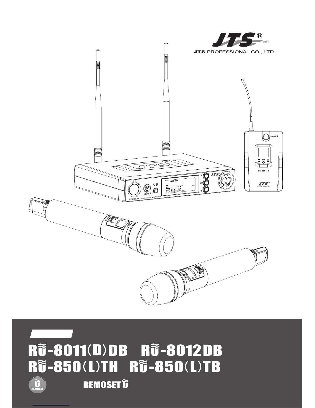
Instruction Manual
UHF PLL
With JTS Ultrasonic Synchronizing Technology
/
/

One year product warranty
Warranty description
1. Be sure to put the warranty label indicating purchase date on the bottom of
equipment to ensure your interest in maintenance and service.
2. Product warranty, starting on the purchase date indicated on “warranty label”, will
last for one year; if the equipment does not have “warranty label”, the warranty
period is 15 months from the manufacturing date. If a microphone is broken but
not sent back with the equipment, the warranty period is 15 months from the
manufacturing date of the microphone.
3. Within the warranty period, if the equipment is broken under normal use as
instructed in manual, please contact the original selling store for repair.
4. When the product is returned for repair, to facilitate proper determination of
cause of malfunction and of whether repair fee is needed, please ship back the
equipment and microphone together.
5. Within the warranty period, our company provides repair service at no cost except for the following conditions that parts and repair may be charged:
a.Damages due to natural disaster or irresistible outside forces.
b.Damages due to drop, water, moisture, corrosion, foreign objects, missing
components.
c.The warranty does not cover consumable parts. (such as microphone capsule,
ball grille etc.)
d.Those without “warranty label” on equipment or with “warranty label” being
damaged and failing to identify warranty period.
6. Please keep the warranty properly. No replacement will be made if the warranty
is missing.
Equipment
serial number
Contact
number
Address
Purchase date
Selling store
stamp
Be sure to put store stamp and ll in purchase date for the warranty to be
eective!
Product Model
Customer
name
1. Notes for system operations
2. Features
3. Specications
3-1 UHF PLL single/dual-channel diversity receiver
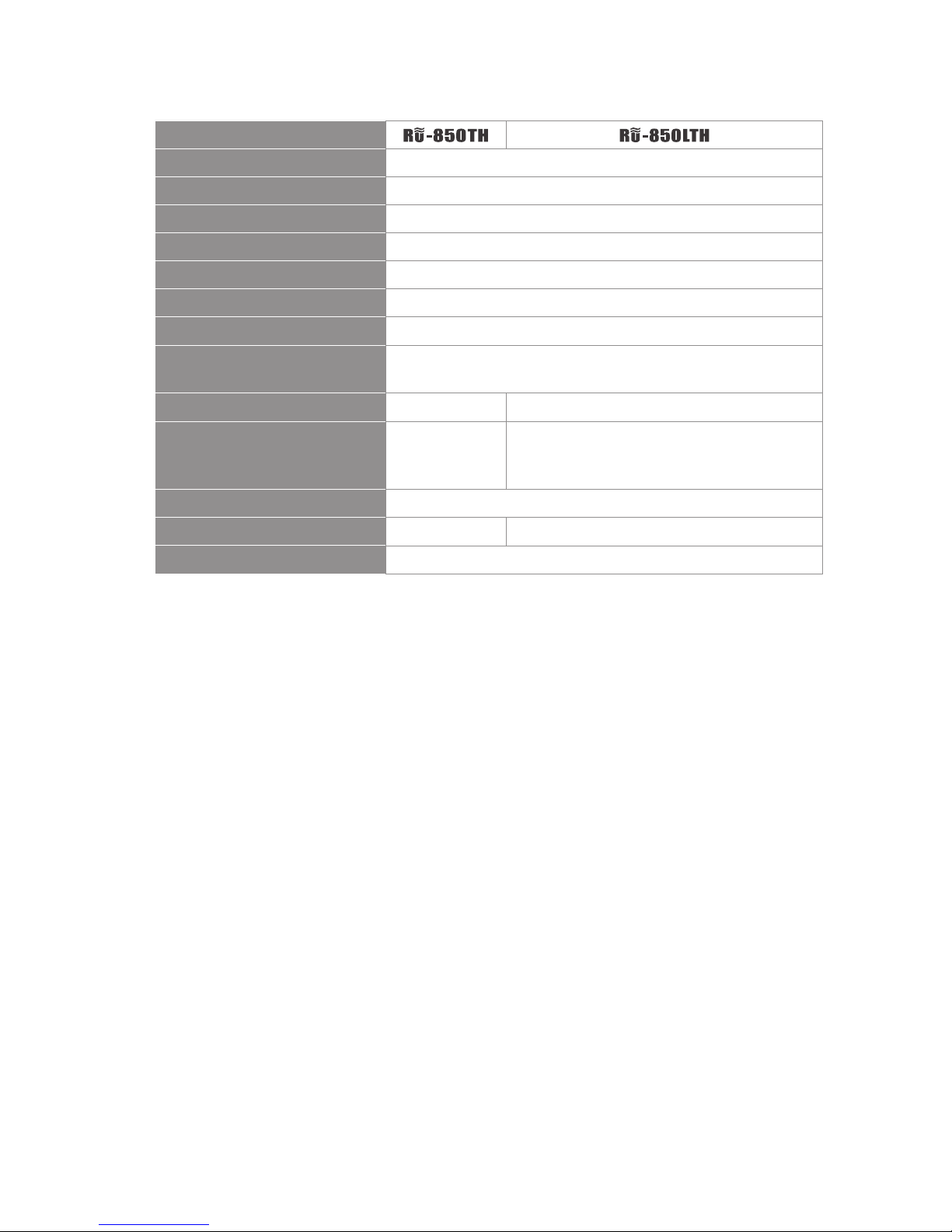
3-2 UHF PLL hand-held transmitter
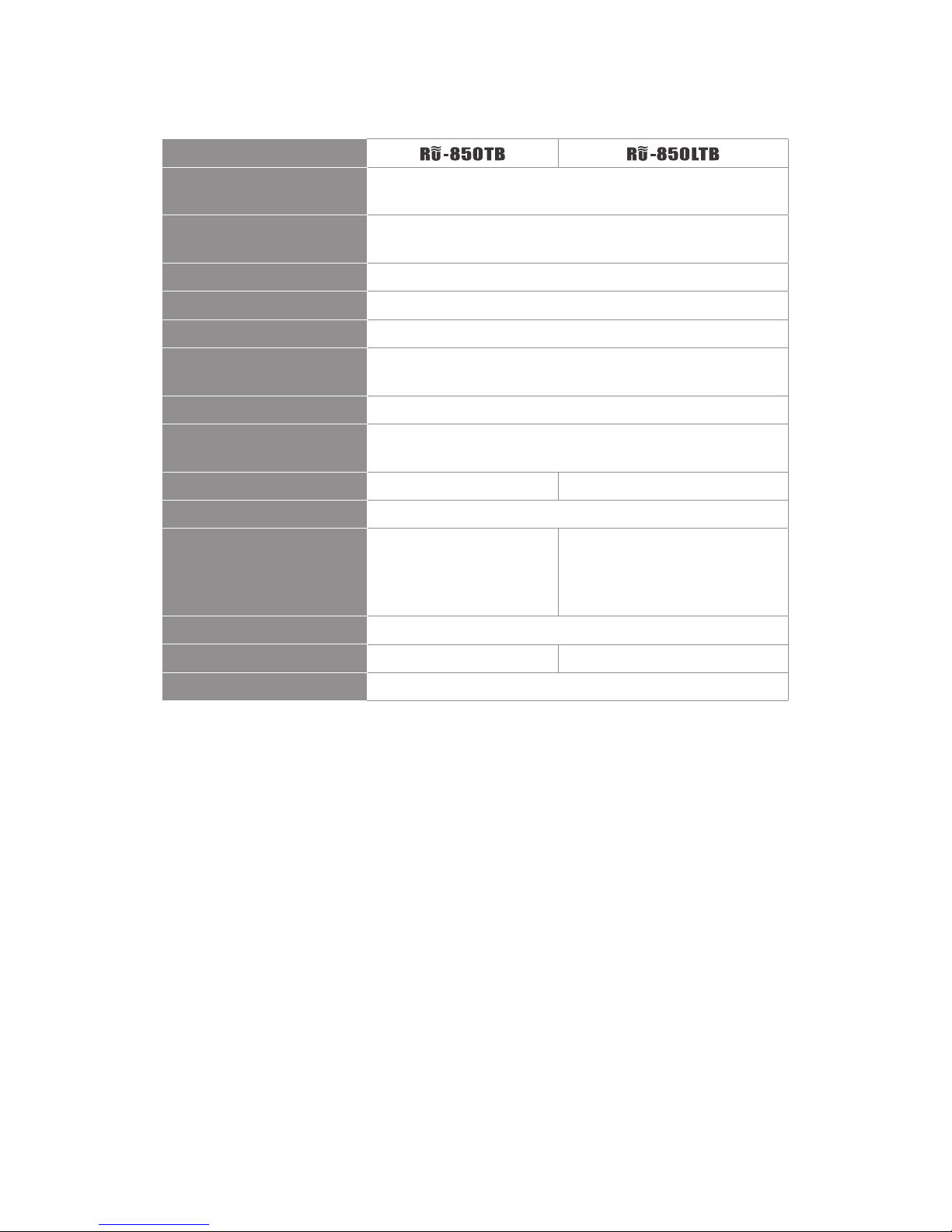
3-3 UHF PLL belt-mount transmitter
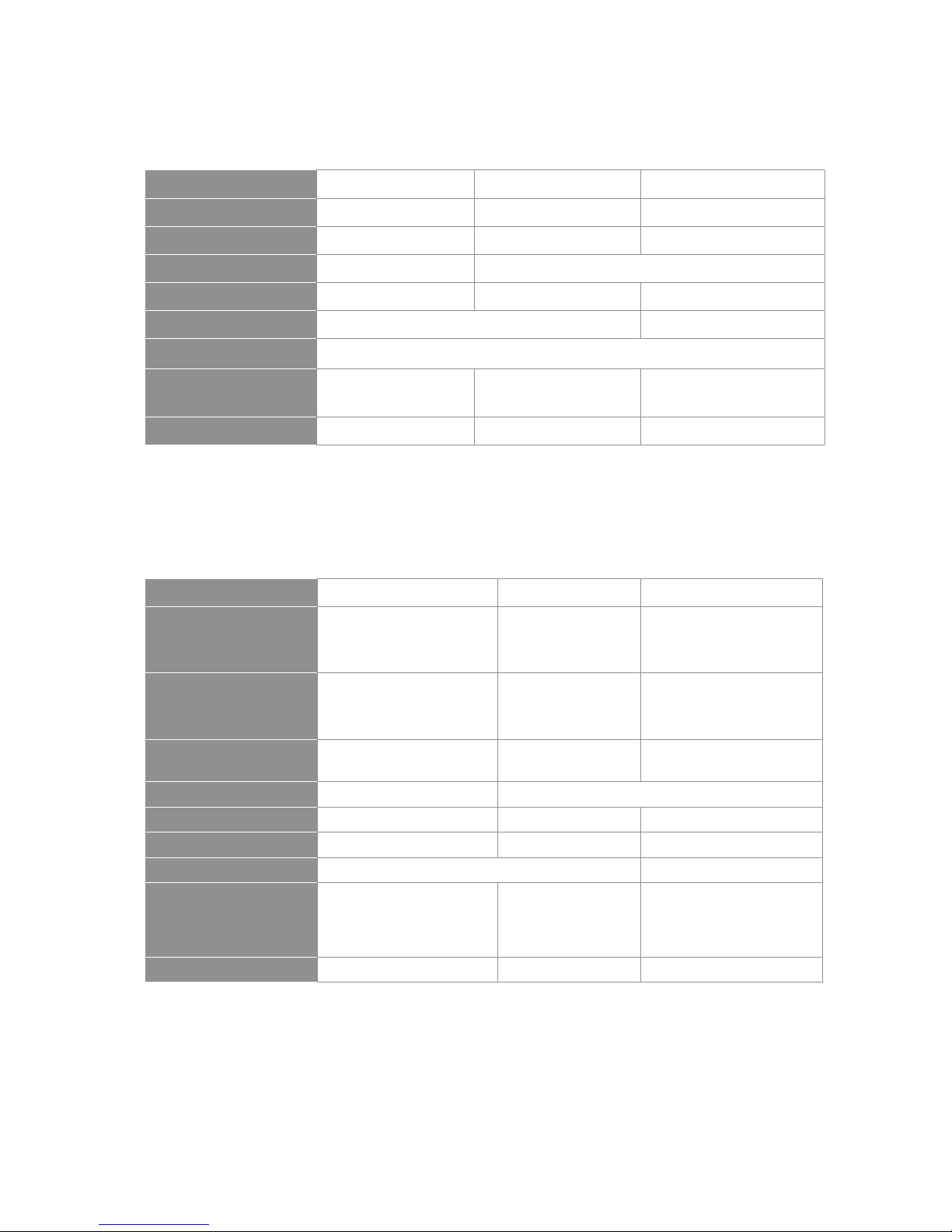
3-4 Optional condenser microphone
4. Description of parts
4-1 UHF PLL single-channel diversity receiver //
4-2 UHF PLL single-channel diversity receiver //
4-3 UHF PLL dual-channel diversity receiver //
4-4 UHF PLL hand-held transmitter //
4-5 UHF PLL hand-held transmitter //
4-6 UHF PLL body-pack transmitter //
4-7 UHF PLL body-pack transmitter //
4-8 Accessories
4-9 Optional Condenser Microphone
5. Connecting
5-1 How to connect the receiver
5-2 Transmitter installation // / / /
6. Instructions for use
6-1 How to use //
6-2 How to use //
6-3 How to use //
6-4 How to use // /
6-5 How to use // /
7. Notes for the product
1
1
2
Table of Contents
2
4
5
6
8
8
10
12
14
15
16
17
18
18
21
21
23
24
24
27
30
33
34
36

1
1. Notes for system operations
2. Features
• Before connecting the power, check that the power requirement shown
on the unit is the same as the power output on the adaptor supplied.
• Do not leave the unit at where the humidity and temperature are high.
• Dry your hands before operating the system.
• Keep the unit away from re and heat source.
• Turn the volume to minimum at both the mixer and amplier before
setting up the system.
• 6 groups are provided as default. Every group contains up to 22 default
channels.
• There are in total 1,440 channels to choose from.
• 36MHz bandwidth.
• The patented ultrasonic pairing for synchronized setting of
all parameters
• Channel scan
• Adjustable receiving sensitivity
• Digital volume control
• Automatic microphone power o
2
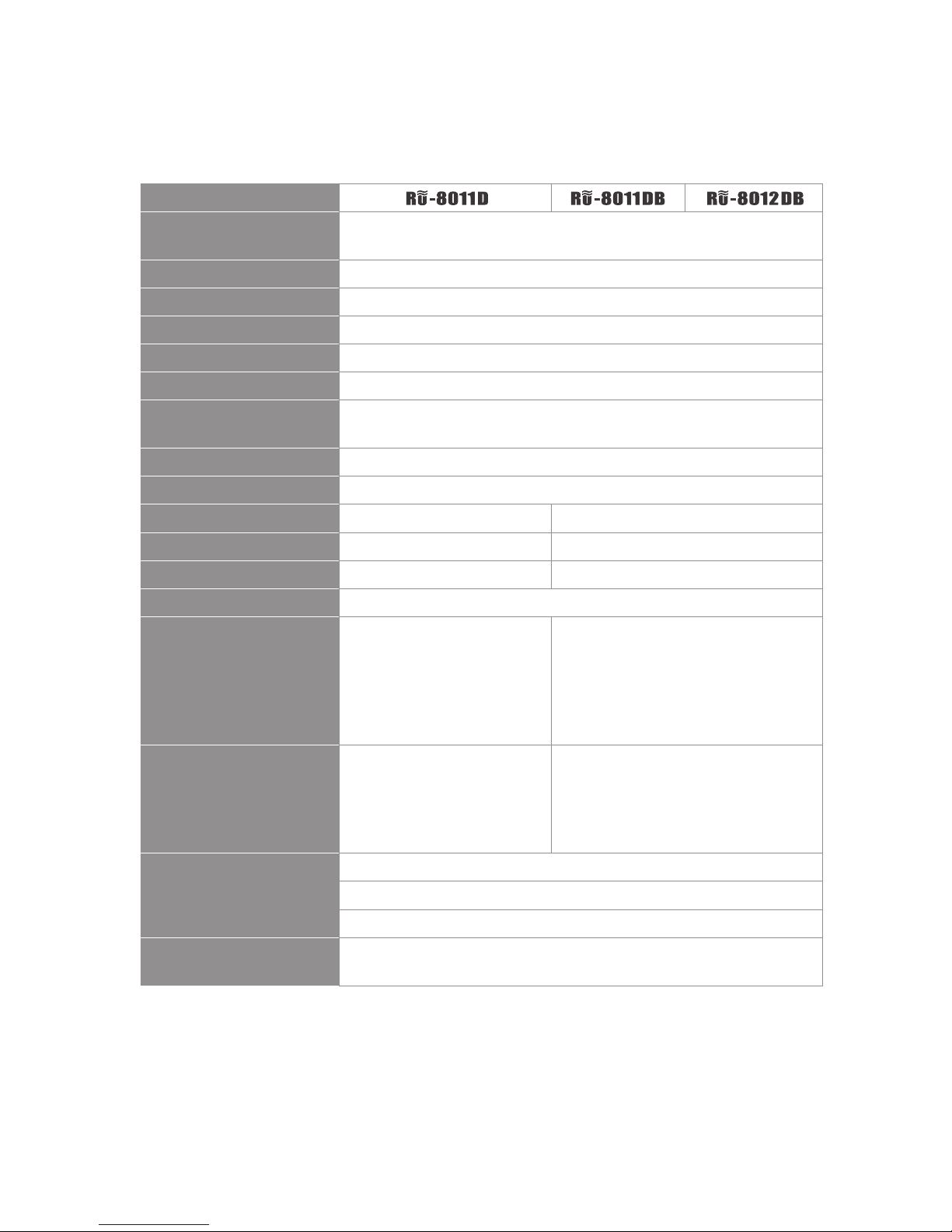
3. Specications
3-1 UHF PLL single/dual-channel diversity receiver
Model
Frequency Oscillation
Mode
Phase-locked loop (PLL)
Carrier Frequency Range 470~ MHz
Remoset Frequency Ultrasonic
Diversity Antennas diversity
Bandwidth 36MHz
Signal/Noise Ratio >105dB(A)
Total Harmonic Distortion
(Thd)
<0.6%@1KHz
Receiving Sensitivity -95dBm,S/N>80dB
Image Rejection Ratio >80 dB
Frequency Response 60Hz~15KHz±2dB 50Hz~16KHz±2dB
Antenna Type Fixed antenna BNC detachable
Antenna Booster Power None DC12~15V/100mA
Function Display By LCD
Contents Of Display
Group, channel, antenna
A/B, muting level, AF
indication, RF indication,
channel scanning, output
level attenuation, volume
indication
Group, channel, frequency, battery
level, antenna A/B, muting level, AF
indication, RF indication, channel
scanning, output level attenuation,
volume indication, machine ID code
Control Functions
Power, group, channel,
muting level, channel
scan (on/o), button lock,
volume, output attenuation
(XLR)
Power, group, channel, frequency,
muting level, button lock, volume,
output attenuation (XLR), channel
scan (on/o)
Audio Frequency Output
Level
Ref:±22.5KHz Dev@1KHz Tone
ψ6.3 Phone Jack:-10dBV
XLR Jack:-4dBV(Line)、-24dBV(MIC)
Audio Frequency Output
Impedance
600Ω

3
Model
Muting Noise muting and tone code locking
Output Port
1 x balanced XLR jack
1 x unbalanced ϕ6.3 jack
2 x balanced XLR
jack
2 x unbalanced
ϕ
6.3 jack
Power Supply
DC12~15V/300mA 12~15V DC /
500mA
Dimension (Mm) 212.3mm (W) x 38.3mm (H) x 144mm (L)
4
3-2 UHF PLL hand-held transmitter
Model
Frequency Oscillation Mode Phase-locked loop (PLL)
Carrier Wave Frequency Range 470~60 MHz
Remoset Frequency Ultrasonic
RF Power Output 10mW/50mW(as per local regulations)
RF Stability <±10KHz@Fc
Modulation Frequency Shift ±48KHz
Harmonic Radiation <-50dBc
Functions
Mute, auto o, input level attenuation, sensitivity
adjustment, low power indication
Display By LED LCD+LED
Controls
Power, mute Power, mute, group, channel, frequency,
sensitivity adjustment, input level
attenuation, auto o, button lock
Battery AA alkali battery or MiNH rechargeable battery x 2
Charging No Yes
Dimension 51mm (W) x 269mm (H) x 26mm (L)
5
Model
Frequency Oscillation
Mode
Phase-locked loop (PLL)
Carrier Wave Frequency
Range
470~60MHz
Remoset Frequency Ultrasonic
RF Power Output 10mW/50mW(as per local regulations)
RF Stability <±10KHz@Fc
Modulation Frequency
Shift
±48KHz
Harmonic Radiation <-50dBc
Functions
Mute, auto o, input level attenuation, sensitivity
adjustment, low power indication
Display By LED LCD+LED
Input Port 4 pin Mini XLR
Controls
Power, mute Power, mute, group, channel,
frequency, sensitivity
adjustment, input level
attenuation, auto o
Battery AA alkali battery or MiNH rechargeable battery x 2
Charging No Yes
Dimension 62mm (W) x 97mm (H) x 20mm (L)
3-3 UHF PLL body-pack transmitter
6
3-4 Optional condenser microphone
Lavaliere microphone
Headset microphone
Model
CM-501 CM-201i CM-125i
Connector
4-pin mini XLR 4-pin mini 4-pin mini XLR
Frequency Response
100~15,000 Hz XLR60~15,000 Hz 50~18,000 Hz
Polar Pattern
Cardioid Omni-directivity
Sensitivity (at 1000Hz) -60 ± 3dB -60 ± 3dB -53 ± 3dB
Impedance
2.2K Ω 4.4K Ω
Max. SPL for 1% THD
130dB
Dimension (mm)
Ø10.1mm (W) x
26.4mm (H)
Ø5mm (W) x
9mm (H)
Ø4mm (W) x
11mm (H)
Net Weight 21.5g 20.7g 7g (cable not included)
Model CM-214i CM-214Ui CM-214ULi
Connector
801C4
(4P Mini XLR)
4P Mini XLR 801C3 (3P Mini XLR)
801C4 (4P Mini XLR)
801CS (3.5 stereo plug)
Option
Connector
801C3 (3P Mini XLR)
801CS (3.5 stereo plug)
801CR
801CR
Frequency Response
60~15,000 Hz 30~18,000 Hz 100 ~ 18,000Hz
Polar Pattern Omni-directional Cardioid
Sensitivity (at 1000Hz) -60±3 dB -68±3 dB -65±3 dB
Impedance 1.8kΩ 680Ω 1.8kΩ
Max. SPL for 1% THD 130dB 120dB
Dimension(mm)
125mm(W) x
134mm(H)x
157mm(D)
205mm(W)x
134mm(H)x
157mm(D)
125mm(W)x
134mm(H)x
157mm(D)
Net Weight 32.9g 38.4g 18g (cable excluded)
7
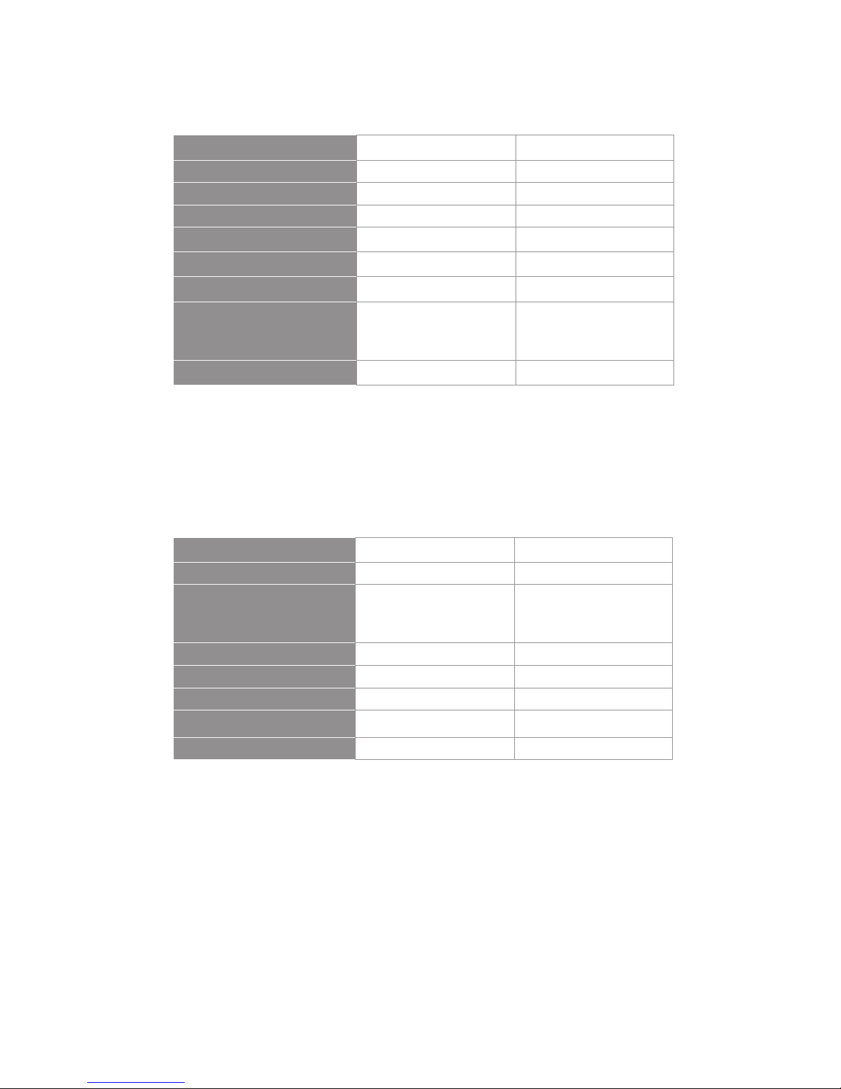
Ear-hook microphone //
Model CM-235i CX-504
Connector 801C4 (4P Mini XLR ) 4P Mini XLR
Frequency Response 50~18,000 Hz 30~18,000 Hz
Polar Pattern Omni-directional Cardioid
Sensitivity (at 1000Hz)
-53 ± 3dB -68 ± 3dB
Impedance
1.8kΩ 680Ω
Max. SPL for 1% THD
130dB
130dB
Dimension(mm)
155mm(W)x
134mm(H)x
157mm(D)
285mm(W)x
55mm(H)x
111.3mm(D)
Net Weight
17g (cable excluded) 56.3g
Model No CM-801 / CM-804i CM-8015 / CM-825i
Connector 801C4 (4P Mini XLR) 801C4 (4P Mini XLR)
Option Connector
801C3 (3P Mini XLR)
801CS (3.5 stereo plug)
801CR
801C3 (3P Mini XLR)
801CS (3.5 stereo plug)
801CR
Frequency Response 60~15,000 Hz 50~18,000 Hz
Polar Pattern Omni-directional Omni-directional
Sensitivity (at 1000Hz) -64±3 dB -53±3 dB
Impedance
1.8kΩ 1.8kΩ
Max. SPL for 1% THD 130dB 130dB

8
4. Description of parts
4-1 UHF PLL single-channel diversity receiver //
Front panel
1
3
25
7
Rear panel
4
8
6
100mA
12V out
Antenna A
100mA
12V out
Antenna B
129
10
11 9
1
4
2
5
3
6
7
8
Receiving antenna: xed antenna of 1/4 wave length
6.3mm phone jack: unbalanced audio output jack
3P XLR male: balanced audio output jack
DC power socket: for 12~15V DC / 300mA power supply
10
12
11
9
Power: means “ON” and means “OFF”
SET: this is for function settings. Push and hold for 2 seconds to enter the
setting mode. Push “SET” repeatedly to search for the function you wish to set.
▲/▼In the setting mode, push▲/▼to change the function parameter
In the non-setting mode: push▲/▼to adjust volume
LCD display
Lock :push and hold “Lock” for 2 seconds to lock the buttons in order to
prevent pushing any button by accident.
Remoset: this allows user to synchronize the transmitter after modifying a
parameter. Push “ ” to synchronize the settings to the transmitter.
Remoset: this shows the current pairing status. It ashes rapidly when data
is being transmitted and the ashing stops when the synchronization is
completed. However, the ashing slows down if synchronization fails after a
period of time of pairing attempt.
Ultrasonic transmission unit: it transmits digital pairing data at ultrasonic
frequency. When setting, direct the ultrasonic receiving element of the microphone to the ultrasonic transmitting element of the receivers. The eective
range is 30º on both sides with the optimized distance at 30cm.
9
15
16
18
14
17
13
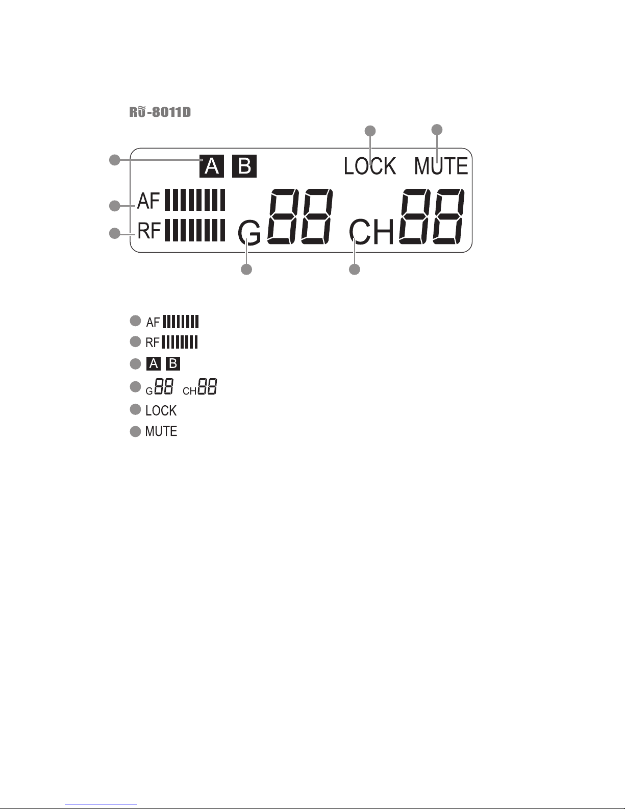
: Audio signal strength
: RF signal strength
: Antenna A/B
: Group / channel
: Button lock engaged
: Receiver mute
In the non-setting mode, the LCD looks like this:
13
14
15
17
18
16
/
16
LCD Display
 Loading...