


Made In Taiwan
AF OUTPUT BALANCED
Freq.:Serial No.:
DCV INPUT
12-15V/500mA
ANT.BANT.A
AF OUTPUT BALANCED
RX2
RX2
RX1
RX1
Mixed
ON
OFF
59508-106-01
No. 148, 9th Industry Road, Ta-Li Industrial Park,
PROFESSIONAL CO., LTD.
Taichung City, Taiwan, R.O.C.
Tel: 886-4-24938803 Fax: 886-4-24914890
E-mail: jts@jts.com.tw
www.jts.com.tw
UHF PLL
R -12
UHF PLL Transmitter
/ /
UHF PLL DUAL CHANNEL DIVERSIT Y RECEIVER
Instruction Manual
With JTS Ultrasonic Synchronizing Technology
3

One year product warranty
Product Model
Customer
name
Address
Purchase date
Selling store
stamp
Be sure to put store stamp and ll in purchase date for the warranty to be
eective!
Warranty description
1. Be sure to put the warranty label indicating purchase date on the bottom of
equipment to ensure your interest in maintenance and service.
2. Product warranty, starting on the purchase date indicated on “warranty label”, will
last for one year; if the equipment does not have “warranty label”, the warranty
period is 15 months from the manufacturing date. If a microphone is broken but
not sent back with the equipment, the warranty period is 15 months from the
manufacturing date of the microphone.
3. Within the warranty period, if the equipment is broken under normal use as
instructed in manual, please contact the original selling store for repair.
4. When the product is returned for repair, to facilitate proper determination of
cause of malfunction and of whether repair fee is needed, please ship back the
equipment and microphone together.
5. Within the warranty period, our company provides repair service at no cost
except for the following conditions that parts and repair may be charged:
a.Damages due to natural disaster or irresistible outside forces.
b.Damages due to drop, water, moisture, corrosion, foreign objects, missing
components.
c.The warranty does not cover consumable parts. (such as microphone capsule,
ball grille etc.)
d.Those without “warranty label” on equipment or with “warranty label” being
damaged and failing to identify warranty period.
6. Please keep the warranty properly. No replacement will be made if the warranty
is missing.
Equipment
serial number
Contact
number
Table of Contents
1. Notes for system operations
2. Features
3. Specications
3-1 UHF PLL dual-channel diversity receiver //
3-2 UHF PLL hand-held transmitter //
3-3 UHF PLL body-pack transmitter //
3-4 condenser microphone (Optional)
4. Description of parts
4-1 UHF PLL dual-channel diversity receiver //
4-2 UHF PLL hand-held transmitter //
4-3 UHF PLL body-pack transmitter //
4-4 In Line Mute Controller (Optional)
4-5 Accessories
4-6 Condenser Microphone (Optional)
5. Connecting
5-1 How to connect the receiver //
5-2 Transmitter installation // /
1
1
2
2
3
4
5
7
7
10
12
13
13
14
16
16
17
6. Instructions for use
6-1 How to use //
6-2 How to use // /
7. Notes for the product
18
18
25
27

1. Notes for system operations
• Before connecting the power, check that the power requirement shown
on the unit is the same as the power output on the adaptor supplied.
• Do not leave the unit at where the humidity and temperature are high.
• Dry your hands before operating the system.
• Keep the unit away from re and heat source.
• Turn the volume to minimum at both the mixer and amplier before
setting up the system.
2. Features
• 6 groups are provided as default. Every group contains up to 22 default
channels.
• There are in total 1,440 channels to choose from.
• 36MHz bandwidth.
• The patented ultrasonic pairing for synchronized setting of
all parameters
• Channel scan
• Adjustable receiving sensitivity
• Digital volume control
• Automatic microphone power o
1

3. Specications
3-1 UHF PLL dual-channel diversity receiver
Model
Frequency Oscillation Mode Phase-locked loop (PLL)
Carrier Frequency Range 470~960 MHz
Remoset Frequency Ultrasonic
Diversity
Bandwidth 36MHz
Signal/Noise Ratio >105dB(A)
Total Harmonic Distortion (Thd) <0.6%@1KHz
Receiving Sensitivity
Image Rejection Ratio >80 dB
Frequency Response 50Hz~16KHz±2dB
Antenna Type 1/2
Antenna Booster Power DC12~15V/100mA
Function Display By LCD
Group, channel, frequency, battery level, antenna A/
Contents Of Display
Control Functions
Audio Frequency Output Level
Audio Frequency Output Impedance 600Ω
Muting Noise muting and tone code locking
Output Port
Power Supply 12~15V DC / 500mA
Dimension (Mm) 212.3mm (W) x 38.3mm (H) x 144mm (L)
B, muting level, AF indication, RF indication, channel
scanning, output level attenuation, volume indication
Power, group, channel, frequency, muting level, button
lock, volume, output attenuation (XLR), channel scan
(on/o)
XLR Jack:-4dBV(Line)、-24dBV(MIC)
Antenna diversity
-95dBm,S/N>80dB
BNC detachable
λ
Ref:±22.5KHz Dev@1KHz Tone
ψ6.3 Phone Jack:-10dBV
2 x balanced XLR jack
2 x unbalanced ϕ6.3 jack
2

3-2 UHF PLL hand-held transmitter
Model
Frequency Oscillation Mode Phase-locked loop (PLL)
Carrier Wave Frequency Range 470~960 MHz
Remoset Frequency Ultrasonic
RF Power Output 10mW/50mW(as per local regulations)
RF Stability <±10KHz@Fc
Modulation Frequency Shift ±48KHz
Harmonic Radiation <-50dBc
Functions
Display By LCD+LED
Controls
Battery AA alkali battery or MiNH rechargeable battery x 2
Charging Yes
Dimension 51mm (W) x 269mm (H) x 26mm (L)
Mute, auto o, sensitivity adjustment, low power indication
Power, mute, group, channel, frequency, sensitivity
adjustment, auto o, button lock
3
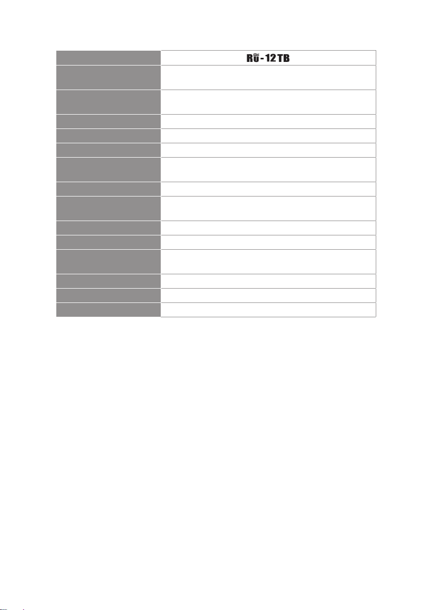
3-3 UHF PLL body-pack transmitter
Model
Frequency Oscillation
Mode
Carrier Wave Frequency
Range
Remoset Frequency Ultrasonic
RF Power Output 10mW/50mW(as per local regulations)
RF Stability <±10KHz@Fc
Modulation Frequency
Shift
Harmonic Radiation <-50dBc
Functions
Display By LCD+LED
Input Port 4 pin Mini XLR
Controls
Battery AA alkali battery or MiNH rechargeable battery x 2
Charging Yes
Dimension 62mm (W) x 97mm (H) x 20mm (L)
Mute, auto o, input level attenuation, sensitivity
Power, mute, group, channel, frequency, sensitivity
adjustment, input level attenuation, auto o
Phase-locked loop (PLL)
470~960MHz
±48KHz
adjustment, low power indication
4
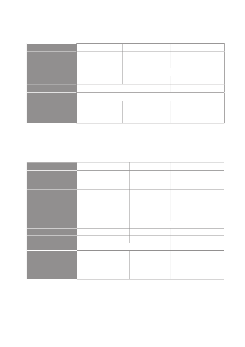
3-4 Optional condenser microphone
Lavaliere microphone
Model
Connector
Frequency Response
Polar Pattern
Sensitivity (at 1000Hz) -60 ± 3dB -60 ± 3dB -53 ± 3dB
Impedance
Max. SPL for 1% THD
Dimension (mm)
Net Weight 21.5g 20.7g 7g (cable not included)
CM-501 CM-201i CM-125i
4-pin mini XLR 4-pin mini 4-pin mini XLR
100~15,000 Hz XLR60~15,000 Hz 50~18,000 Hz
Cardioid Omni-directivity
2.2K Ω 4.4K Ω
130dB
Ø10.1mm (W) x
26.4mm (H)
Ø5mm (W) x
9mm (H)
Ø4mm (W) x
11mm (H)
Headset microphone
Model CM-214i CM-214Ui CM-214ULi
801C4
Connector
Option
Connector
Frequency Response
Polar Pattern Omni-directional Cardioid
Sensitivity (at 1000Hz) -60±3 dB -68±3 dB -65±3 dB
Impedance 1.8kΩ 680Ω 1.8kΩ
Max. SPL for 1% THD 130dB 120dB
Dimension(mm)
Net Weight 32.9g 38.4g 18g (cable excluded)
(4P Mini XLR)
801C3 (3P Mini XLR)
801CS (3.5 stereo plug)
801CR
60~15,000 Hz 30~18,000 Hz 100 ~ 18,000Hz
125mm(W) x
134mm(H)x
157mm(D)
4P Mini XLR 801C3 (3P Mini XLR)
801C4 (4P Mini XLR)
801CS (3.5 stereo plug)
801CR
205mm(W)x
134mm(H)x
157mm(D)
125mm(W)x
134mm(H)x
157mm(D)
5
Model CM-235i CX-504
Connector 801C4 (4P Mini XLR ) 4P Mini XLR
Frequency Response 50~18,000 Hz 30~18,000 Hz
Polar Pattern Omni-directional Cardioid
Sensitivity (at 1000Hz)
Impedance
Max. SPL for 1% THD
Dimension(mm)
Net Weight
-53 ± 3dB
1.8kΩ 680Ω
130dB
155mm(W)x
134mm(H)x
157mm(D)
17g (cable excluded) 56.3g
-68 ± 3dB
130dB
285mm(W)x
55mm(H)x
111.3mm(D)
Ear-hook microphone
Model No CM-801 / CM-804i CM-8015 / CM-825i
Connector 801C4 (4P Mini XLR) 801C4 (4P Mini XLR)
801C3 (3P Mini XLR)
Option Connector
Frequency Response 60~15,000 Hz 50~18,000 Hz
Polar Pattern Omni-directional Omni-directional
Sensitivity (at 1000Hz) -64±3 dB -53±3 dB
Impedance
Max. SPL for 1% THD 130dB 130dB
801CS (3.5 stereo plug)
801CR
1.8kΩ 1.8kΩ
801C3 (3P Mini XLR)
801CS (3.5 stereo plug)
801CR
6

4. Description of parts
4-1 UHF PLL dual-channel diversity receiver //
Front panel
7
2
R -12
3
6
1
Power: means “ON” and means “OFF”
2
SET: this is for function settings. Push and hold for 2 seconds to enter the setting
48
3
2
5
UHF PLL DUAL CHANNEL DIVERSITY RECEIVER
1
mode. Push “SET” repeatedly to search for the function you wish to set.
3
▲/▼In the setting mode, push▲/▼to change the function parameter
In the non-setting mode: push▲/▼to adjust volume
4
LCD display
5
Lock :push and hold “Lock” for 2 seconds to lock the buttons in order to prevent
pushing any button by accident.
6
Remoset u : this allows user to synchronize the transmitter after modifying a parameter. Push “ ” to synchronize the settings to the transmitter.
7
Remoset indicator : this shows the current pairing status. It ashes rapidly when
data is being transmitted and the ashing stops when the synchronization is completed. However, the ashing slows down if synchronization fails after a period of
time of pairing attempt.
8
Ultrasonic transmission unit: it transmits digital pairing data at ultrasonic frequency.
When setting, direct the ultrasonic receiving element of the microphone to the ultrasonic transmitting unit of the receivers. The eective range is 30º on both sides with
the optimized distance at 30cm.
7

Rear panel
13
9 9
14
Made In Taiwan
AF OUTPUT BALANCED
RX1
RX1
RX2
Mixed
ON
OFF
AF OUTPUT BALANCED
Freq.:Serial No.:
RX2
DCV INPUT
12-15V/500mA
ANT.BANT.A
12 1110 15
9
Female BNC antenna port: the 50Ω BNC antenna is connected here. It
also provides a booster power of 12~15 DC / 100mA for an external
antenna booster.
Male XLR (RX1): RX1 balanced audio output jack
10
Male XLR (RX2): RX2 balanced audio output jack
11
12
Mixing: it allows the unbalanced audio signals from RX1 and RX2 to be
mixed to RX1.
13
6.3mm phone jack (RX1): RX1 unbalanced audio output jack
14
6.3mm phone jack (RX2): RX2 unbalanced audio output jack
15
DC power socket: for 12~15V DC / 500mA power supply
8

RU-12 LCD display content
12
1
9
1
7
8
2
3
4
5
6
1011
8
3
13
Content Displayed under the Non-Setting Mode:
1
2
3
4
5
6
7
8
9
10
Setup Menu
11
RX1: Set the Receiver's Channel 1. RX2: Set the Receiver's Channel 2.
12
1: Set the Receiver's Channel 1. 2: Set the Receiver's Channel 2.
13
Display the settings of the same item for another Receiver's Channel.
: Radio Frequency Signal Intensity
: Audio Signal Intensity
:Antenna Selection A/B The Receiver is mute.(MUTE)
: Transmitter Battery Level
:Frequency (Group/Channel)
: Frequency
: Key Lock (Key Lock ON)
: Volume
: Digital Code is ON. (DigiCode ON)
2
9

4-2 UHF PLL hand-held transmitter //
1
Power: push to turn the transmitter on. When the transmitter is on, push and
hold for 2 seconds to turn it o.
2
Mute: while the transmitter is on, switch Mute up to talk and down to mute. If
the transmitter is o, switch the Mute up to turn the unit on. The transmitter
turns itself o automatically after 1, 10 or 30 minutes of muting depending on
setting.
3
Ultrasonic receiving unit: it receives pairing signals from the ultrasonic
transmission unit at the receiver end.
4
Battery holder: it holds UM3, AA 1.5V battery or rechargeable battery x 2.
5
LED indicator: it shows the transmitter’s status, including battery level, mute and
pairing indication.
6
LCD display: it shows the parameter settings in the transmitter.
7
SET: it allows parameter settings, including frequency, group, channel, sensitivity,
transmission power, auto o countdown and machine code.
8
▲/▼: these are used with “SET” to change the parameter settings.
9
: push and hold the “LOCK” button for 2 seconds to lock the buttons. Push and
hold again for 2 seconds to unlock.
6
5
9
1
2
7
8
4
3
10

Light Signal Indicator
Green: The Battery Level is sucient >2V.
Flash Green: The Microphone is mute.
Red: The Battery Level is insucient ≦2V.
Alternate Flash Red/Green:
LED Light
The Microphone is mute.
(The Battery Level is not insucient.)
Blue: The light signal ashes for 5 seconds, indicating that
frequency matching is successful.
Flash Blue: Data Receiving Error
Others
The charging function is supported. The Transmitter will be shut down automati-
cally when charged. When Battery Level<1.8V, the Transmitter will force itself to
activate the shutdown process. When it is turned o, if the Mute Switch is in the
mute section, turning up the switch can directly trigger the power on.
11

4-3 UHF PLL body-pack Transmitter //
Functions of the Panel
1
The LCD shows the parameters and settings of the Transmitter.
2
The Ultrasound Receiving Hole
REMOSET Indicator Light: Blue Light: The light ashes for 5 seconds, indicating
3
that frequency matching is successful. Flash Blue: Data Receiving Error
4
Power Key:
(1)ON: Simply press the Power Key.
OFF: Press and hold the Power Key for 2 seconds, until the display shows that
the power is o.
(2)Click the Power Key in the Setup Menu to return to the home screen.
5
▲、▼: Up/Down arrow keys for upward/downward selection.
6
SET: Set and save.
7
Mute Switch/LED Display: (1) The green light will ash when the power is on.(2)
The red light will ash at low voltage.(3) Mute the Transmitter is muted when
switched to the "MUTE" position, and the Green Light Signal will ash.(4) When
the Transmitter is "MUTE" + at low voltage, the red/green lights will ash alter-
nately.
8
Battery Slot
7
1
2
3
4
UHF PLL Transmitter
5
6
8
12

4-4 In Line Mute Controller
Option
1
Microphone Mute Key
2
Operating Mode Control Key
3
Microphone
4
4P mini XLR
5
Ø 2.5mm Signal Wire
1
5
2
4-5 Accessories
1
AC/DC adaptor
Switching Power Supply(100V~240V , 50~60Hz)
AC IN: AC100~240V/50~60Hz
DC OUT: DC12V/0.5A
2
AF output cable (with Φ6.3 plug at both ends)
Option
PT-RMS
mic
3
4
13
3
AA alkaline battery
4
RU-12 Ear rack
1 2
3
4

4-6 Optional Condenser Microphone
Lavaliere Microphone // CM-501 CM-201i CM-125i
1
Clip
2
4 Pin Mini XLR
3
Windscreen
2
CM-501 CM-201i CM-125i
1
1
3
3
1
3
Headset Microphone // CM-214i CM-214Ui CM-214ULi CM-235i CX-504
1
Gooseneck
2
Adjustable headband
3
Headband
4
4 Pin Mini XLR
5
Windscreen
2 2
CM-214i
5
1
CM-214Ui CM-214ULi
5
1
2
Standard :
4 Pin Mini XLR
3 Pin Mini XLR
3.5 Stereo Plug
5
1
2
CM-235i
4
5
1
3
CM-504
5
1
14

Ear-hook Microphone // CM-801 CM-804i CM-8015 CM-825i
1
Boom
2
Adjustable Headband
3
Adjustable ear hook
4
Detchable Cable
5
Cable Clip
6
Windscreen
7
4 Pin Mini XLR
8
3 Pin Mini XLR
9
3.5 Stereo Plug
10
4Pin Hirose connecter
8 97 10
Option
Option
6
Option
1
CM-801
6
3
4
5
3
2
15
CM-804i
1
6
1
4
CM-8015
5
6
2
CM-825i
1
4
5
3
2
4
5

5. Connecting
5-1 How to connect the receiver
1. Connect the audio output of receiver to mixer or amplier
1.1 :
(1) The XLR output jack or 6.3mm unbalance output jack can be selected
individually to connect the AF output to a mixer or amplier for volume
control.
(2) Switch the “Mixed” on the back to ON. This allows to mix the RX1 and RX2
signals to RX1’s 6.3mm non-balance output jack and then to a mixer or
amplier for volume control.
2. Connect the power
2.1. Connect the AC/DC adapter:
Check that the DC current and voltage ratings of the adapter match the
label on the unit. Connect the DC terminal to the “DC input” port on the unit,
and the AC end to an AC socket.
2.2. Set the parameters:
Turn the power on and set the parameters of receiver according to the
setting instructions.
Caution! Secure the power cable on the fastening hook of anti-pulling clip in
order to prevent the power cable from falling.
Amplie
AC/DC adaptor
Wall socket
Step1
Made In Taiwan
AF OUTPUT BALANCED
Freq.:Serial No.:
RX1
RX1
RX2
Mixed
ON
OFF
AF OUTPUT BALANCED
RX2
Step 2
DCV INPUT
12-15V/500mA
ANT.BANT.A
16

5-2 Transmitter installation //
-1
I
633.875
G: 1 C
UF-20TB
Hi
The Mute button on the hand-held unit also triggers the power-on. That’s why the
unit is on as soon as the batteries are replaced. Therefore, if you do not wish to turn on
after changing the batteries, keep the Mute switch on mute.
1. Unscrew the outer tube of the transmitter (Figure 1).
2. Place 2 AA batteries in the battery holder while make sure they are in the correct
polarities (Figure 2).
3. Screw the outer tube on (Figure 3).
4. To turn the unit on:
a. Push the power button to turn on (Figure 4a), or
b. Push the Mute switch up also to turn the unit on (Figure 4b).
5. Set the transmitter parameters according to the instructions.
Fig. 1
Fig. 2
Fig. 3
Fig. 4a Fig. 4b
1. Slide the battery holder cover downwards (Figure 1).
2. Place 2 AA batteries in the battery holder while make sure they are in the correct
polarities (Figure 2).
3. Slide the battery holder cover upwards to close (Figure 3)
4. According to the type of microphone, insert the 4-pin mini XLR jack in MIC IN to
complete the installation (Figure 4).
5. Push the Power button to turn the unit on (Figure 5).
6. Set the transmitter parameters according to the instructions.
17
Hi
UF-20TB
G: 1 C: 11
633.875 MHz
IDoff
Fig. 1
Hi
UF-20TB
G: 1 C: 11
633.875 MHz
Fig. 2
AT
IDoff
Hi
UF-20TB
G: 1 C: 11
633.875 MHz
IDoff
UHF PLL Transmitter
Fig. 3
AT
Fig. 4 Fig. 5

6. Instructions for use
6-1 How to use //
Press and hold the SETUP key for 2 seconds to enter the
Setup Menu. Press ▲ and ▼ keys to select the item to
be set, and press SETUP again to enter the settings.
※ Press to return to the previous item. Note that the
set value will not be saved.
◎Frequency Setting
Adjust the left 3 digits of the Frequency. Press ▲ and
▼ keys to change by "+/-" 1 MHz each time. Press the
SETUP key after adjustment is completed. Adjust the
right 3 digits of the Frequency. Press ▲ and ▼ keys to
change by“+/-” 0.025MHz each time. After the setup is
completed, press the SETUP key to save the set value.
◎Default Group
Press ▲ and ▼ keys to select Group "G:" ; Press the SET-
UP key adjustment is completed. Press ▲ and ▼ keys
to adjust Channel "CH:" After adjustment is completed,
press the SETUP key to save the set value.
18

◎The Scanning Function
Scan All Groups. Press the SETUP key to start scanning. After the scan is completed, the “Scan Results
List” screen will be displayed automatically. Users can
also click on the menu to enter the “Scan Results List”
directly.
“Scan Results List”: Press the SETUP key to enter the
menu screen and view the scan results. Select the
available channels, and press the SETUP key to save the
settings.
Scanning the current Group: Upon entry into the
screen, press ▲ and ▼ keys to select the group to be
scanned, and press SETUP to start scanning. Press ▲ to
search for the previous available Channel.
19

Press ▼ to search for the next available Channel. Press
the SETUP key to save the settings.
◎Receiver Sensitivity
+10 ~ -5: The higher the value, the lower the Receiver
Sensitivity; the lower the value, the higher the Receiver
Sensitivity. Default Value is 0.
◎Output Attenuation
Press ▲to set the balanced output level for Line to
Line output.
Press ▼ to set the balanced output level for Mic to
Mic output.
◎Microphone Options: Press ▲ and ▼ to select the
item to be adjusted. Press SETUP, and then press ▲ and
▼ to select the settings to be adjusted, and then press
SETUP to return to the item selection.
20

Sensitivity
Scope of Adjustment:
-15dB~+15dB;Default Value is 0.
Input Attenuation
ON Audio input is attenuated by 20dB. (Depend-
ing on whether the transmitter has this
function)
OFF Not Attenuated (Default Value)
This function only applies to the Waist-Mounted Trans-
mitter RU-12TB.
Radio Frequency Power
High High Transmitting Power 50mW
Low Low Transmitting Power 10mW(Default Value)
Automatic shutdown (when the Microphone is muted)
OFF This function is turned o.
1 min Automatic shutdown after 1 minute
10min Automatic shutdown after 10 minutes
30min Automatic shutdown after 30 minutes
21

Synchronization Options
Press ▲ and ▼ to select and
synchronize transmission of the setup items, and then
press the SETUP key to perform the selection action.
□ Frequency
□ Sensitivity
□ Input Attenuation (RU-12TB only)
□ Radio Frequency Power
□ Automatic shut-down
□ Digital Audio Code
□ Key Lock
□ Save and Exit
□ Return
◎Key Lock
(Digital anti-interference function)
ON Key Pad Lock ON
OFF Key Pad Lock OFF
◎System Settings
◎Display Settings
Contrast 0~9 (Default Value5)
Brightness 0~9 (Default Value5)
22

◎Language
Yes Reset to the set values original manufacturer
settings
No Return to the previous option
◎Reset to original manufacturer settings
◎Exit the Setup Screen.
Press the SETUP key to exit the setup screen and return
to the home screen.
23

Pairing
Once the parameters are set, push the “ ” button and the
digital pairing data will be sent to the transmitter via ultrasonic transmitter
for parameter synchronization. The indicator will ash rapidly while the data
are being transmitted. When the synchronization is completed, the receiver
will receive the corresponding data and the indicator will stop ashing. If
the signal is not received for a certain period of time, the indicator will ash
slowly to inform pairing failure (the slowly ashing indicator can be reset by
pushing any button).
Note: The best pairing distance is 10~60cm, ±30º.
-30 +30
10~60cm
Note2: Only one Microphone can be synchronized at a time. When RX1 is synchronized, RX2
cannot be synchronized. RX2 must wait until RX1 is disconnected from synchronization.
Others
The LCD screen will display the Transmitter Battery Level simultaneously. If the Battery Level
≦ 2V, the battery’s outer frame will ash and the backlight will become Red as a warning.
(Model RU-12)
24

6-2 How to use // &
Parameter Setup
Press the SET key for 2 seconds to enter the setup mode. Press the SET button repeatedly to enter dierent setting items in order. Press ▲/▼ to set the parameters. Press
SET again to save and exit the settings.
◎FREQ Frequency Setup
1MHz as a unit Press ▲/▼ to set the Frequency
0.025MHz as a unit Press ▲/▼ to set the Frequency
◎Group/Channel Settings
G Group Select Default Group1~6
CH Channel Select Default Channel, up to 23
Note: A:Frequency Band 1, B:Frequency Band 2, C:Frequency Band 3
◎Sensitivity: Microphone Input Sensitivity
Normal
Sensitivity
GAIN:+15dB
GAIN:+14dB
GAIN:
GAIN:+2dB
GAIN:+1dB
GAIN:0dB((Default Value)
GAIN:-1dB
GAIN:-2dB
~~~
GAIN:
GAIN:-14dB
GAIN:-15dB
◎ATT. Audio Input attenuation
At oFF Audio input is not attenuated.
At on Audio input is attenuated by 20dB.
This function only applies to RU-12TB.
25
The chart shows that Sensitivity is currently set
to Gain 0dB (Default Value).
The chart shows that the audio input is
currently attenuated by 20 dB.

◎RFP Microphone Radio Frequency Power
The Transmitter contains two sections for Radio
Frequency Power output adjustments (depending
on local regulations).
rFP Lo 10mW(Default Value)
rFP Hi 50mW
Radio Frequency
Power:Low
Radio Frequency
Power:High
◎AUTO-OFF: The Microphone's Automatic Shutdown Time (in the MUTED state)
OFF Turn o this function.
1 Automatic shutdown after 1 minute
10 Automatic shutdown after 10 minutes
30 Automatic shutdown after 30 minutes
Note: The Default Value is set to 10 minutes.
◎Digital Audio Code(Digital anti-interference function)
ON Turn on the Digital Audio Code
OFF Turn o the Digital Audio Code(If the
receiver’s digital code function is en-
abled, the receiver will be muted.)
◎Key Lock
Loc on Lock ON (Locked)
Loc oFF Lock OFF (UnLocked)
Others
The charging function is supported. The Transmitter will be shut down automatically
when charged. When Battery Level<1.8V, the Transmitter will force itself to activate the
shutdown process.
26

7. Notes for the product
(1)
For the best signal receiving quality, always keep the receiver within 3m of the
transmitter.
(2)
The receiver and transmitter shall be away from other metal objects, preferably
50cm or farther.
(3)
Do not point the microphone directly to a speaker, or there will be feedbacks.
It is recommended to hold the transmitter (microphone) at the middle section for
the best pickup.
In case that the transmitter will not be in use for an extended period of time, the
(4)
batteries shall be removed from the battery holder to prevent damage to the
transmitter due to leak of battery electrolyte solution.
For the best power performance, it is recommended to change both batteries or
(5)
use the products of the same manufacturer when they are to be changed.
27
 Loading...