

Page 1
UHF PLL Single Channel Diversity Wireless System
* The system is the initiative design to allow changing the transmitter’s
frequency by long-distance worldwide.
* Preset 4 groups each of 16 UHF channels.
Music
Life
INFINITY
Page 2

INFINITY
Life
1. Important Caution
2. Features
3. Parts Identification
3-1 IN64R
3-2 IN64TH
3-3 IN64TB
3-4 Power supply unit
4. Connection
1. Connect to the subsequent unit
2. Connect the power supply unit
5. Operation
1. Set up the system
2. Set up ID code
3. Synchronize the channel
4. Check system status
5. Adjust output volume
6. Manual select channel
7. REMOSET button lock
8. Adjust the sensitivity of the microphone
6. Specification
01
01
02
02
03
04
04
05
05
05
06
06
06
07
08
09
09
10
11
13
Page 3
01
1. Important Caution
Always make all connections before plugging the unit into an AC power outlet.
Do not leave the devices in a place with high temperature or high humidity.
Always do not handle the power cord with wet hands !
2. Features
JTS IN64 wireless microphone s
setting function (REMOSET). A user can set the receiver with desired frequency and
press the “REMOSET” Key; then the transmitter will automatically be set. The operation
distance can reach 10 meters. This brings great convenience to sound engineers
during live performance.
A new capsule has been developed for IN64TH (Optional) . The capsule, SAM-8W,
is designed for large venue with hundreds of thousands watt power. The SAM-8W
delivers vivid details of vocal and instruments.
The IN64 is of stylish industry design. Yet JTS bombproof quality remains as
always.
Page 4
Music
INFINITY
Life
02
3. Parts Identification
3-1 IN64R
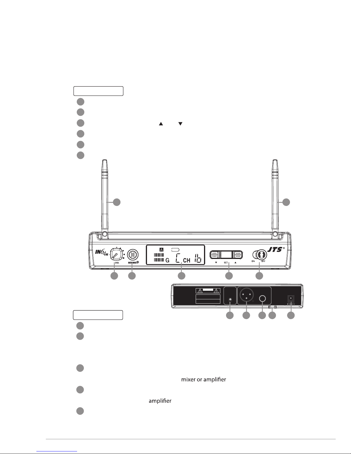
Front panel
Receiving Antennas
Power Switch
Channel Select:
including “ up”, “ down” and “Set” button
LCD Panel
REMOSET Key:
press it to send a desired channel data to a transmitter
Volume Control
Rear panel
Power Supply Jack (12-18V/600mA): for connecting the power supply unit
Strain Relief: for the connection cable of the power supply unit, which lead the cable
around the hook to prevent accidental disconnection of the plug from
the jack.
AF Output (6.3mm jack, balance): for connection to a balance input, e.g. of a
Balanced XLR Output: for connection to the balanced input, e.g. of a mixer or an
Output Level Attenuation(-20dB): to attenuate the balanced output level by 20dB
AF
RF
0dB
-20dB
AF
OUTPUT
OUTPUT
LEVEL
Serial No.:
Freq.Range:
RISK OF ELECTRIC SHOCK
DO NOT OPEN
CAUTION
DCV INPUT
12-18V/200mA
BALANCED BALANCED
1
2
3
4
5
6
7
8
9
10
11
1 1
23456
7891011
Page 5
03
a
b
c
d
e
f
g
12
13
14
15
16
17
AF
RF
a
b
d
c
e
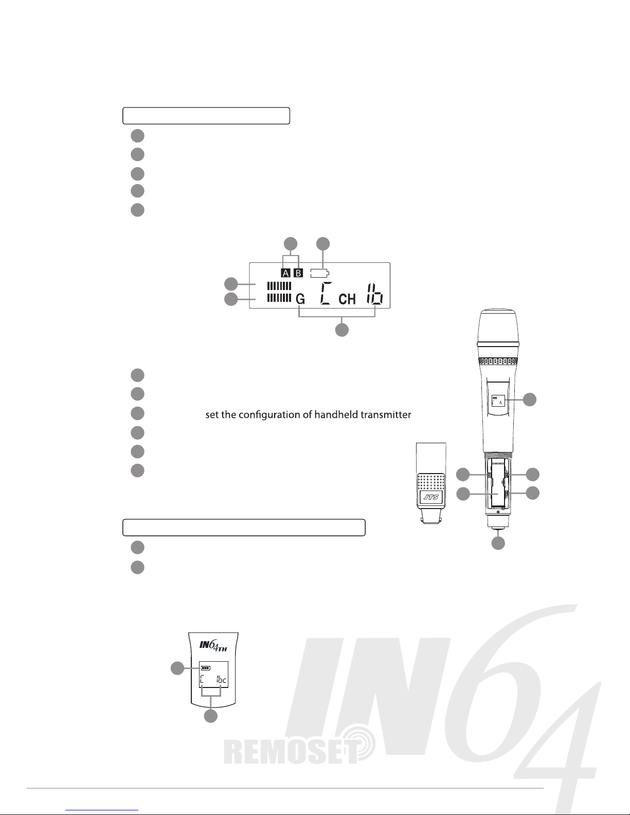
LCD Panel of the Receiver
AF Level: display the strength of audio signal
RF Level: display the strength of radio signal
Antenna Status: the receiver will automatically select an antenna with stronger signal level
Low battery indicator: display the low battery status of its transmitter
Group & Channel: there are four groups, A, B, C, and D with 16 Channels each
3-2 IN64TH
LCD Display
Battery Tray
Set button:
Up button: select the settings of transmitter
Down button: select the settings of transmitter
Power and Mute Switch
LCD Panel of the Handheld Transmitter
Battery status: display battery status
Group & Channel: there are four groups, A, B, C, and D with 16 Channels per
group
f
g
+
-
12
IN
4
6
TH
SET
14 15
16
13
17
Page 6
Music
INFINITY
Life
04
h
i
18
19
20
21
23
22
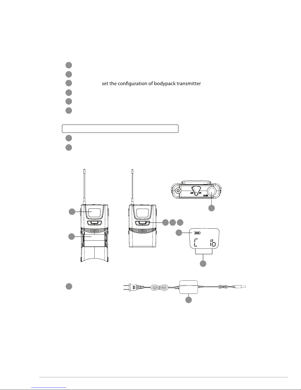
3-3 IN64TB
LCD Display
Battery Tray
Set button:
Up button: select the settings of transmitter
Down button: select the settings of transmitter
Power and Mute Switch
LCD Panel of the Body-Pack Transmitter
Battery status: display battery status
Group & Channel: there are four groups, A, B, C, and D with 16 Channels per group
24
3-4 Power supply unit
AC/DV adaptor
24
18
20 21 22
23
19
-
i
h
Page 7
05
MIXER
AUDIO OUTPUT
DC INPUT
Figure 1
0dB
-20dB
AF
OUTPUT
OUTPUT
LEVEL
Serial No.:
Freq.Range:
CAUTION
DCV INPUT
12-18V/200mA
BALANCED BALANCED
24 7
9
8
10
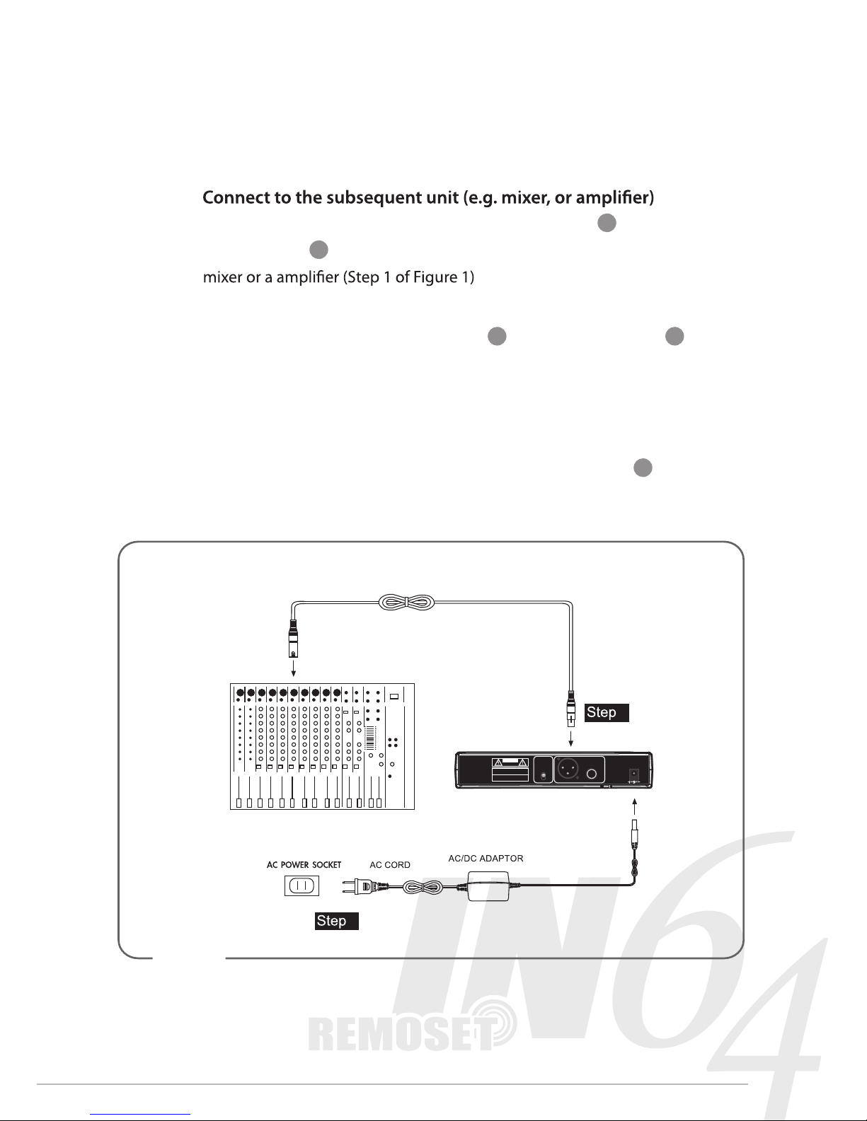
4. Connection
1.
Connect one end of a proper AF cable to the AF Output or Balanced XLR
Output socket , then plug another end to the “MIC IN” input socket of a
2. Connect the power supply unit
Plug in one end of AC/DC adaptor cable to Power Supply Jack in the
rear panel of receiver, and plug another end into an AC outlet
(Step 2 of Figure 1)
Caution
To prevent accidental disconnection of the plug of the power supply unit
from the jack, lead the cable around the hook for strain relief
2
1
Page 8
INFINITY
Life
06
5. Operation
1. Set up the system
A) Turn on the power of the receiver
Switch the “Power Switch” to “ON”. The “LCD Panel” and “REMOSET”
Key will light up.
Turn on the power of the transmitter
Hold the “Power Switch” for 3 seconds. The “LCD Display”
will light up.
Mute Function
After the transmitter's power is on, short pressing the "Power Switch "
will mute the microphone. Press the "Power Switch" again will re-activate
the microphone.
Notice: You have to hold the "Power Switch" for 3 seconds in order to turn
B)
Put the antennas in a vertical position
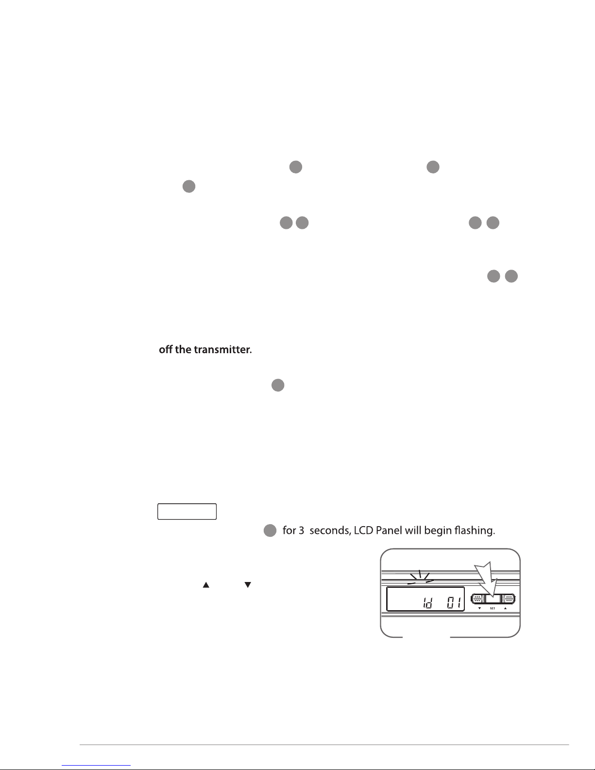
2. Set up ID code
In order to match one receiver to only one transmitter, IN64 is designed
with“ ID code”. If and only if both ID codes of a receiver and a transmitter
match each other, the “REMOSET” function works. There are 100 ID codes
available.
A) Press "Set" button
B) Press "Set" twice to enter "ID Code"
setting window. (Figure 2)
C) Press " Up" or Down" button to select
a distinct ID code from "id 0" to "id 99"
D) After setting, press "Set" again to save the
settings.
2
5
4
17 23 12 18
1
3
17 23
Figure 2
Receiver
Page 9
07
3
3
Handheld and BodyPack transmitter
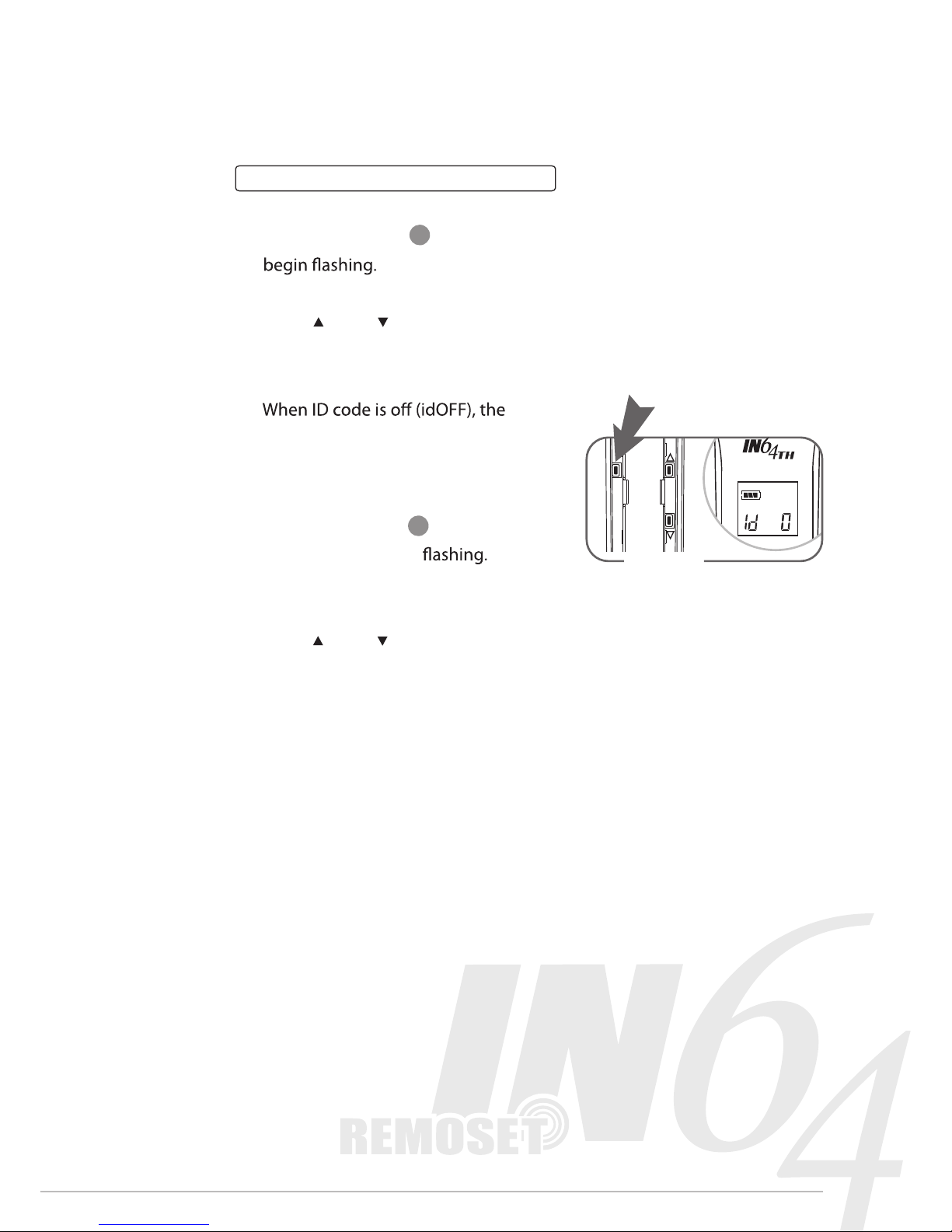
ID code ON/OFF setting
A) Press "Set" button for 3 seconds, LCD Panel will
B) Press "Set" couple times until "ID Code ON/OFF" setting window shows.
C) Press " Up" or Down" button to select between " ID ON " and " ID OFF ".
D) After setting, press "Set" again to save the settings.
Caution
transmitter will accept any
synchronization from any receiver.
ID code selecting
A) Press "Set" button for 3 seconds,
LCD Panel will begin
B) Press "Set" couple times until "ID Code"
setting window shows.
C) Press " Up" or Down" button to select a
distinct ID code from " id 0" to "id 99 ". (Figure 3)
D) After setting, press "Set" again to save the settings.
SET
Figure 3
3”
Page 10
INFINITY
Life
08
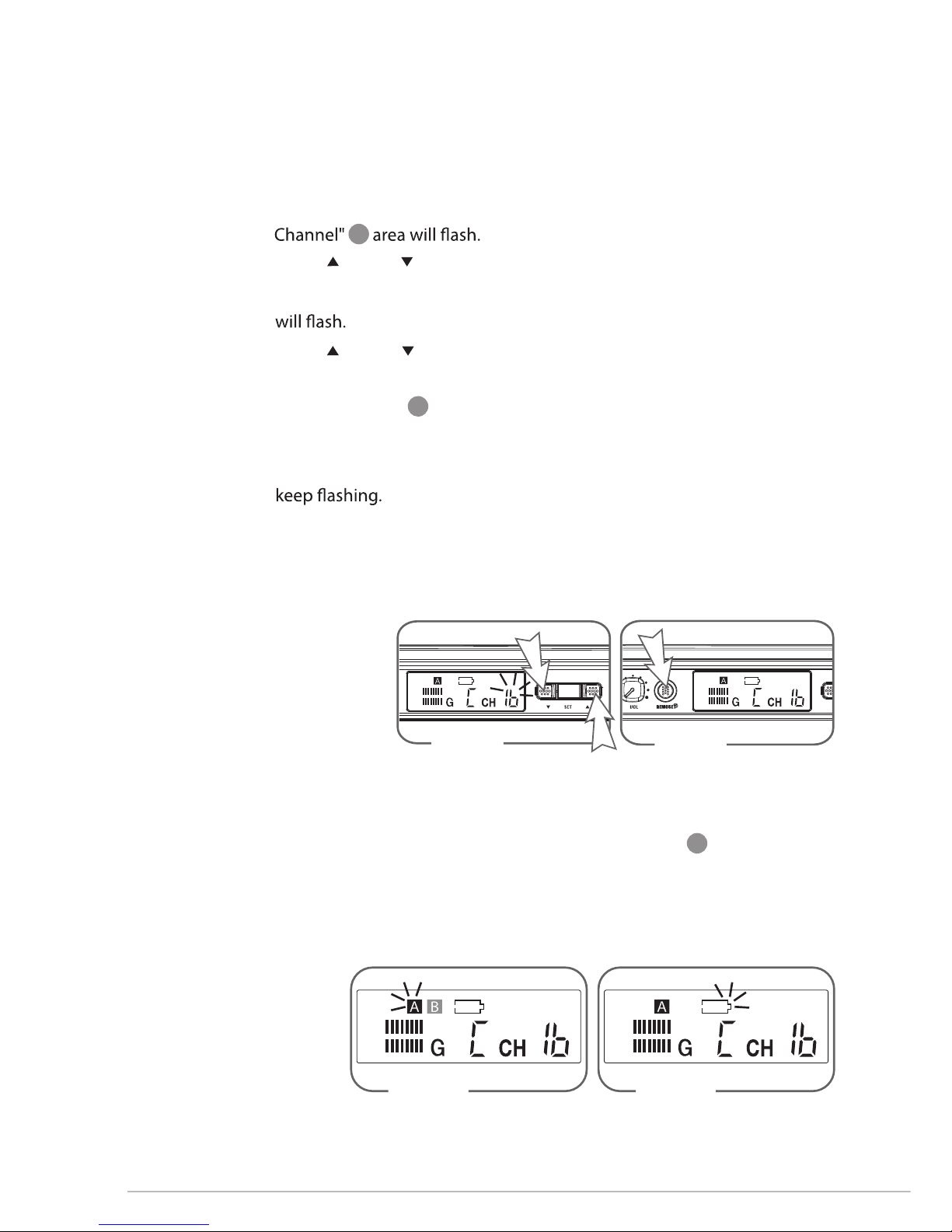
4. Check system status
A) Antenna Status: the receiver will automatically select an antenna with
stronger signal reception and highlight that antenna (Figure 6)
B) Low Battery indicator: when synchronization succeeds, if the
transmitter is under low battery status, the "low battery indicator" will
appear. (Figure 7)
Figure 6
AF
RF
Figure 7
AF
RF
c
3. Synchronize the channel
A) Press "Set" button for 3 Seconds, the group (G) in the "Group &
(Figure 4)
B) Press " Up" or " Down" button to select a desired group
C) Press "Set" again and the Channel (CH) in the "Group & Channel" area
D) Press " Up" or " Down" button to select a desired channel.
E) After setting, press “Set” again to save the settings.
F) Press "REMOSET" to synchronize the channel of a transmitter.
(Figure 5)
G) If the channel of the transmitter fails to change, the "REMOSET" key will
Notice: The transmitter has to be set to "synchronization on (SYnOn)"
in order to allow the receiver to synchronize.(Handheld and bady Pack
Setting List p.12 )
AF
RF
Figure 5
AF
RF
Figure 4
5
e
Page 11
09
5. Adjust output volume:
Adjust output volume by twisting the Volume Control
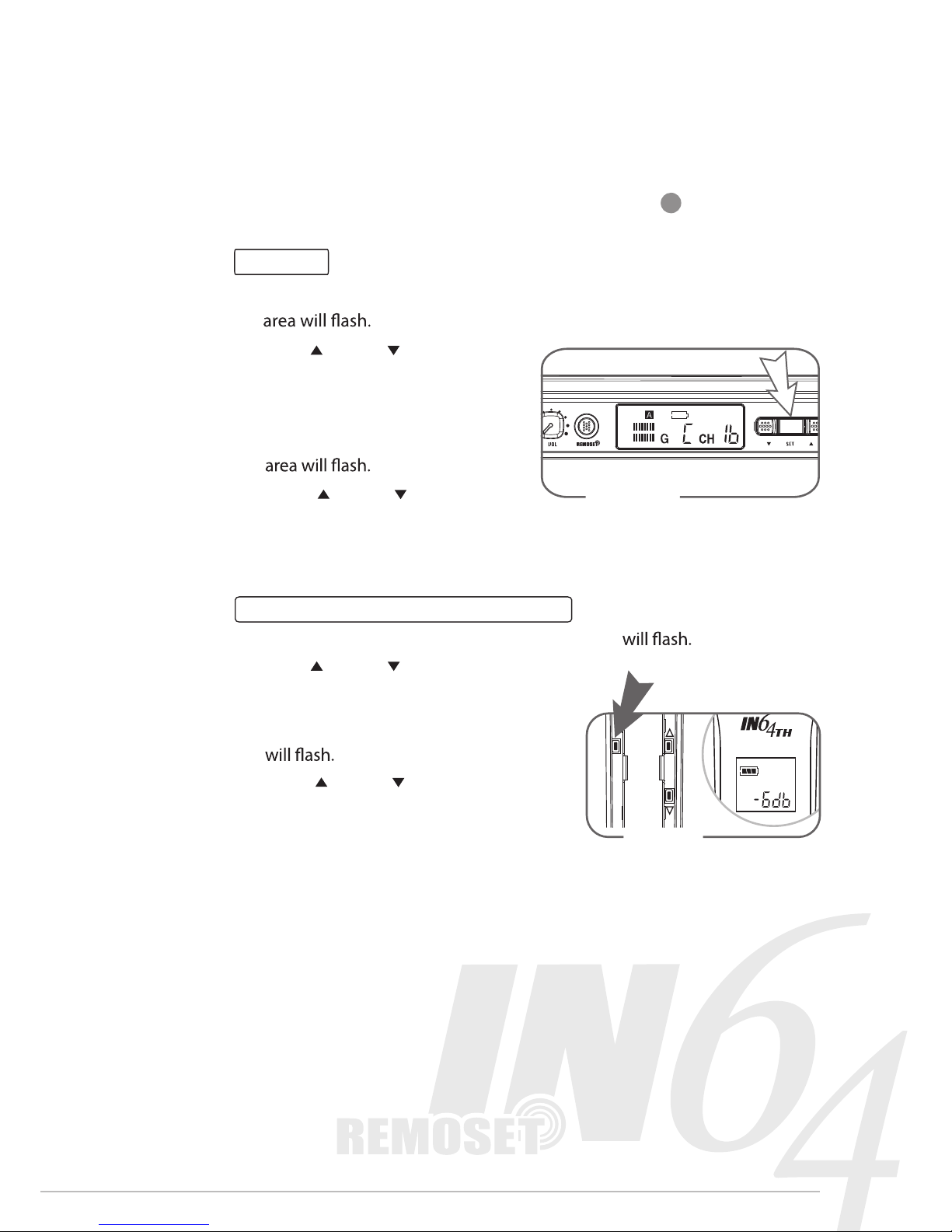
6. Manual select channel:
Receiver
A) Press "Set" button for 3 seconds, the group (G) in the "Group & Channel"
(Figure 8)
B) Press " Up" or " Down" button
to select a desired group
C) Press "Set" again and the Channel
(CH) in the "Group & Channel"
D) Press " Up" or " Down" button
to select a desired channel.
E) After setting, press “Set” again to save the settings.
Handheld and BodyPack transmitter
A) Press "Set" button for 3 seconds, the group (G) (Figure 9)
B) Press " Up" or " Down" button to select
a desired group
C) Press "Set" again and the Channel (CH)
D) Press " Up" or " Down" button to
select a desired channel.
E) After setting, press “Set” again to save
the settings.
6
SET
Figure 9
3”
AF
RF
Figure 8
Page 12
INFINITY
Life
10
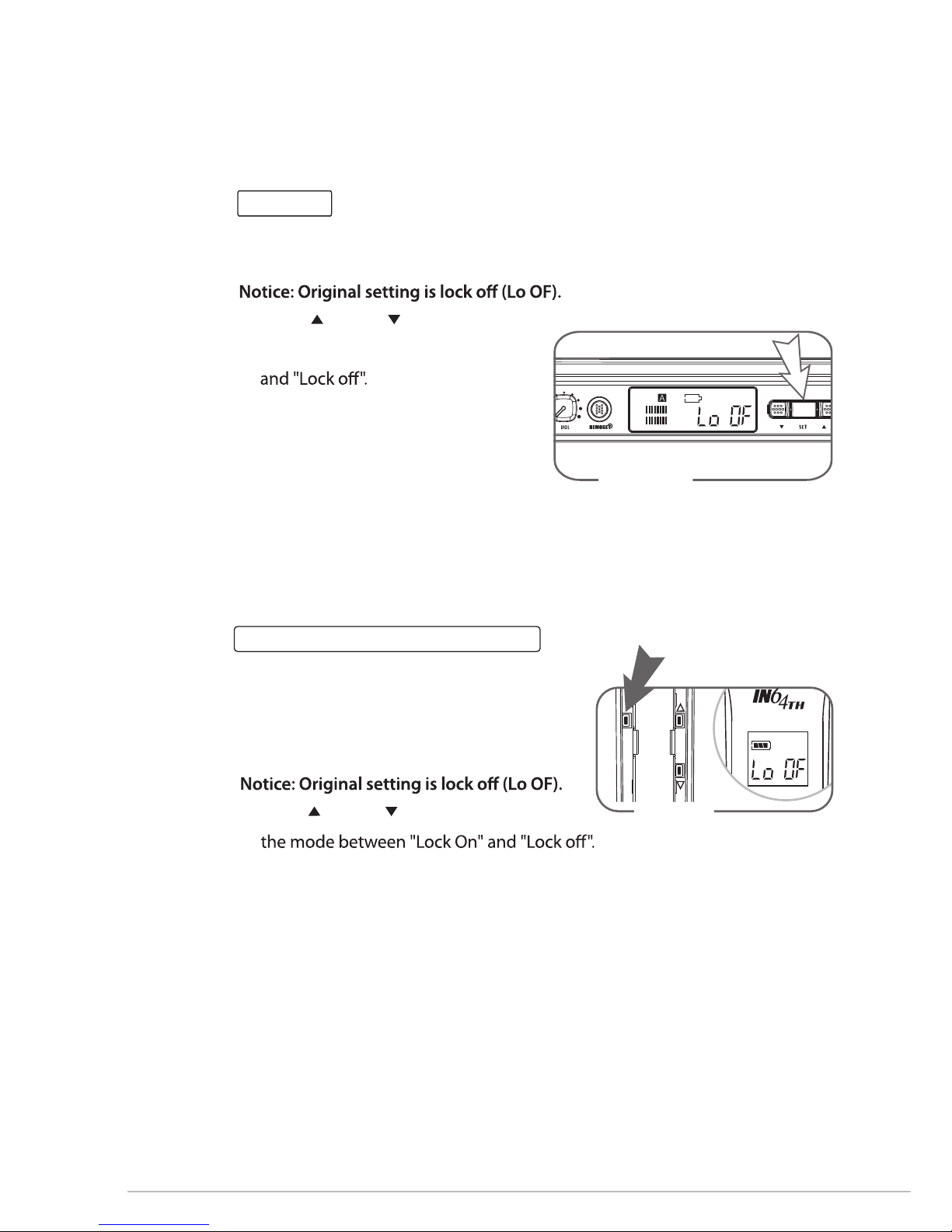
7. Lock ON Function:
Receiver
A) Press "Set" button for 3 seconds to enter setting window
B) Press "Set" again until the Lock setting window shows. (Figure 10)
C) Press " Up" or " Down" button to
select the mode between "Lock On"
D) After setting, press "Set" again to
save the settings.
To release the “Lock ON”
A) Press “Set” for 2 seconds.
B) Press “down” to select “Lock OFF”.
C) Press “Set” to store.
Handheld and BodyPack transmitter
A) Press "Set" button for 3 seconds to enter
setting window. (Figure 11)
B) Press "Set" again until the Lock setting
window shows.
C) Press " Up" or " Down" button to select
D) After setting, press "Set" again to save the settings.
To release the “Lock ON”
A) Press “Set” for 2 seconds.
B) Press “down” to select “Lock OFF”.
C) Press “Set” to store.
SET
Figure 11
3”
AF
RF
Figure 10
Page 13
11
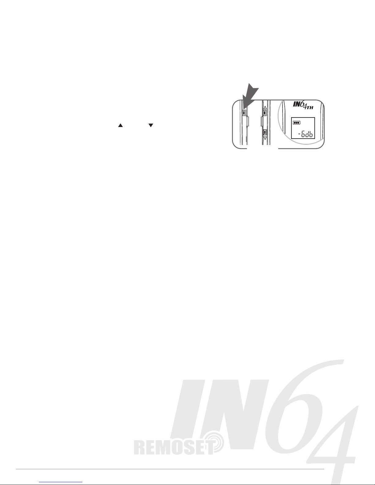
8. Adjust the sensitivity of the microphone
A) Press "Set" button for 3 seconds to enter
setting window.
(Figure 12)
B) Press "Set" again until the Sensitivity
setting window shows.
C) Press " Up" or " Down" button to
select the sensitivity among 0db,
-6db,-12db,and -18db.
D) After setting, press "Set" again to
save the settings.
SET
Figure 12
3”
Page 14
INFINITY
Life
12
~
~
~
~
~
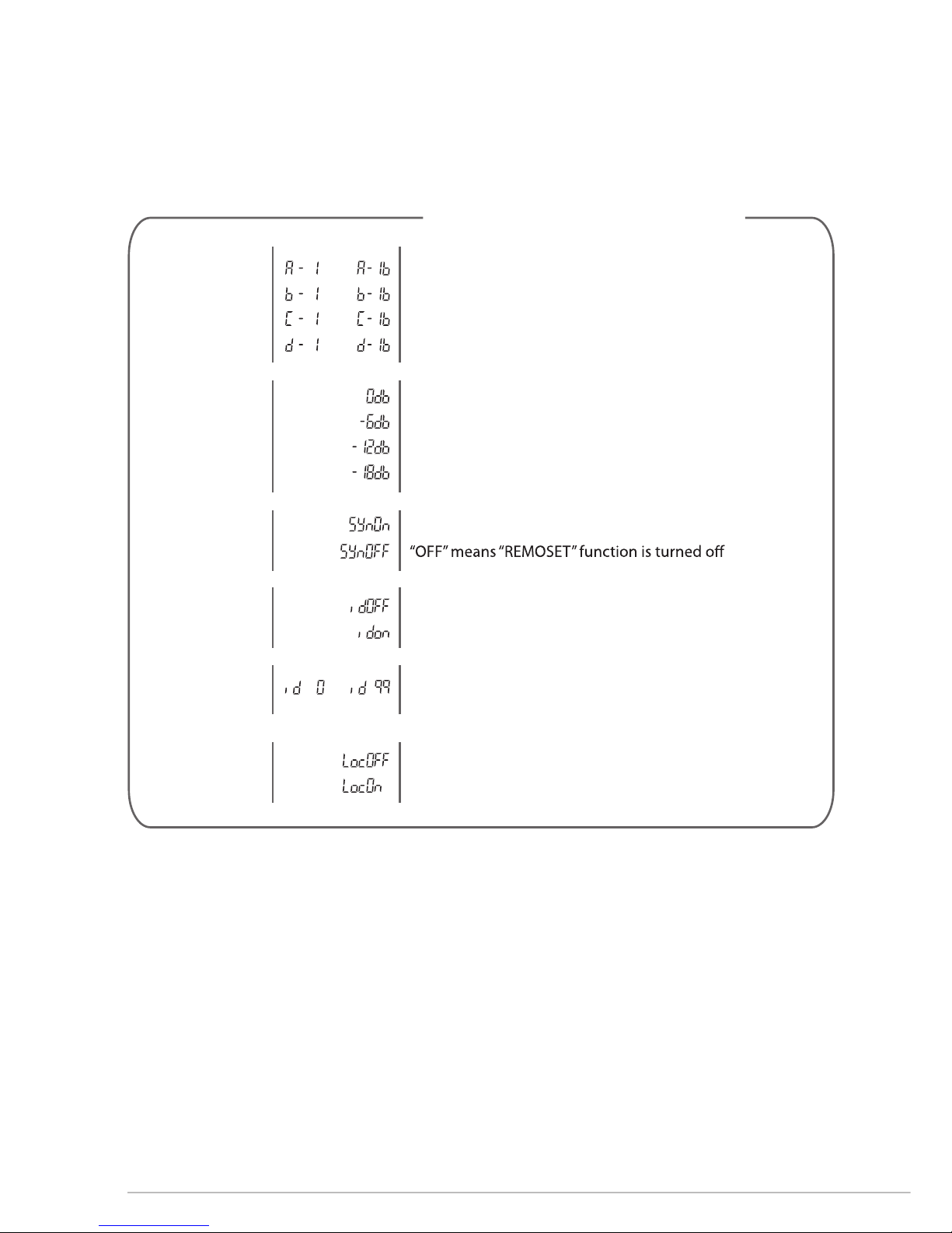
Handheld and body Pack Setting List
Sensitivity
Settings
Synchronization
ON/OFF
Manual Channel
Select
0 dB is the highest sensitivity
There are 100 ID codes.
When ID code is OFF (id OFF), the transmitter will
accept any synchronization from any receiver.
There are 4 groups with 16 channel per group
“On” means “REMOSET” function always opens;
ID code ON/OFF
ID code select
Lock ON
button unlock
button lock
Page 15

13
6. Specification
6-1 IN64R
6-2 IN64TH
6-3 IN 64TB
Frequency Preparation
Remoset
Carrier Frequency Range
S/N Ratio
T.H.D (1 KHz)
Display
Display Contents
Controls
Audio Output Level
AF Output Impedance
Squelch
Operation Voltage
Output Connector
Dimension(m/m)
PLL Synthesized Control
Radio Frequency,2.4GHz
Effective distance: 10m
494MHz~960MHz
>105dB
<0.6%@1KHz
LCD
Channel, Antenna A/B, Mute Display, RF/AF
Level Meter, Low battery, ID Number
Power On/Off, Frequency Up/Down, Audio Level,
Lock-on, ID Pairing, Remoset
-12dB
600Ω
Pilot Tone & Noise Mute
12-18 VDC, 600 mA
1 XLR Balanced Socket
1 φ6.3mm balanced phone jack
212mm(W) * 44mm(H) * 215mm(D)
PLL Synthesized Control
494MHz~960MHz
10mW
±0.005%
±48kHz
Channel, Battery Fuel Gauge, ID Number
Power On/Off, AF Level,
Frequency Up/Down, Lock-on Mode, ID Pairing
<-50 dBC
50Hz~16kHz
UM3, AA 1.5V*2
Frequency Preparation
Carrier Frequency Range
RF Outputs
Stability
Frequency Deviation
LCD Display
Controls
Spurious Emissions
Audio Frequency Response
Battery
Frequency Preparation
Carrier Frequency Range
RF Outputs
Stability
Frequency Deviation
LCD Display
Controls
Spurious Emissions
Audio Frequency Response
Battery
PLL Synthesized Control
494MHz~960MHz
10mW
±0.005%
±48kHz
Channel,
Battery Fuel Gauge, ID Number
Power On/Off, AF Level,
Frequency Up/Down,
Lock-on Mode, ID Pairing
<-50 dBC
40Hz~18kHz
UM3, AA 1.5V*2
Page 16
Music
AF
RF
59508-017-01
 Loading...