

JTS IN264R, IN264TH, IN264TB User Manual
59508-021-02
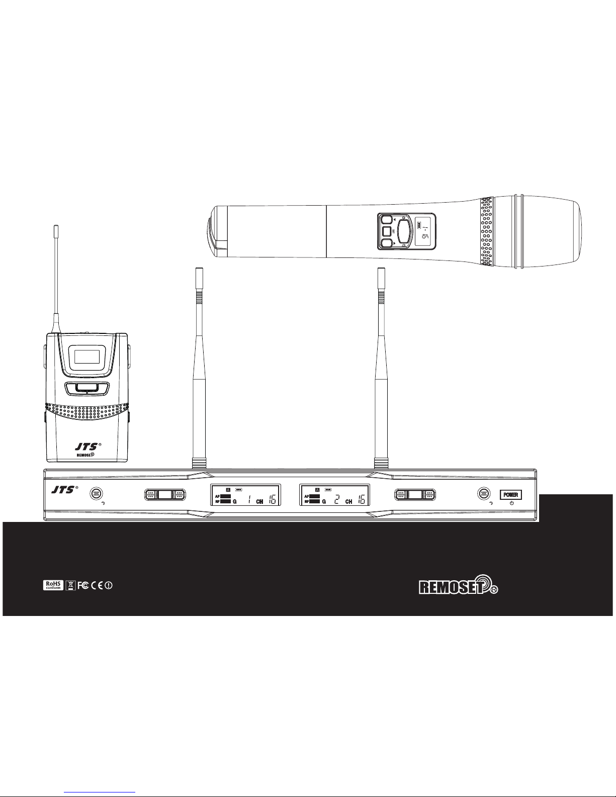
UHF PLL Dual Channel Diversity Wireless System
* The system is of the innovative design to allow changing the
transmitter’s frequency by long-distance .
* IN264R with band width of 36 MHz.
* Preset 6 groups, maximum 23 channels in one group.
2
IN
4
6
REMOSET
IN
4
2
6
R
SET ▲
▲
REMOSET
SET ▲
▲
AF
RF
AF
RF
Music
Life
INFINITY
SET
+
-
IN
4
2
6
TB

Music
INFINITY
Life
01
2
IN
4
6
1. Important Caution
2. Features
3. Parts Identification
3-1 IN264R
3-2 IN264TH
3-3 IN264TB
3-4 Accessories
4. Connection
4-1 Connect to the subsequent unit
4-2 Connect the power supply unit
5. Operation
5-1 Set up the system
5-2 Set up ID code
5-3 Synchronize the channel
5-4 Check system status
5-5 Manual select channel
5-6 REMOSET button lock
5-7 Adjust the sensitivity of the microphone
6. Specification
01
01
02
02
03
04
04
05
05
05
06
06
06
07
08
09
10
11
13
1. Important Caution
Always make all connections before plugging the unit into an AC power outlet.
Do not leave the devices in a place with high temperature or high humidity.
Do not handle the power cord with wet hands !
Keep the devices away from re and heat sources.
Pair the ID codes of the transmitter and the receiver to have proper function.
2. Features
JTS IN264 wireless microphone system is designed with the world rst RF
remote setting function (REMOSET). A user can set the receiver with desired
frequency and press the “REMOSET” Key; then the transmitter will automatically be
set. The operation distance can reach 10 meters. This brings great convenience to
sound engineers during live performance.
IN264 is of 36MHz bandwidth to render 23 transmitters work simultaneously.
It provides great convenience to large venue.
A new capsule has been developed for IN264TH . The capsule, SAM-8W, is
designed for large venue with hundreds of thousands watt power. The SAM-8W
delivers vivid details of vocal and instruments.
The IN264 is of stylish industry design. Yet JTS bombproof quality remains as
always.
2
IN
4
6
Music
INFINITY
Life
02 03
REMOSET
IN
4
2
6
R
SET ▲
▲
REMOSET
SET ▲
▲
AF
RF
AF
RF
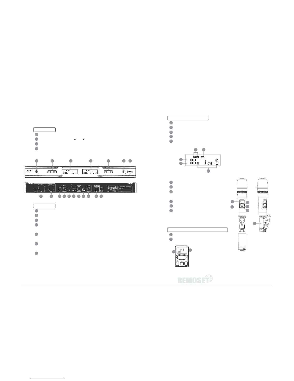
3. Parts Identification
3-1 IN264R
Front panel
Power Switch
Channel Selector:
including “ up”, “ down” and “Set ” button
LCD Panel
REMOSET Key:
press it to send a desired channel data to a transmitter
Rear panel
BNC antenna connector
Power Supply Jack (12-18V/600mA):
for connecting the power supply unit
Squelch adjuster: to adjust radio signal level of both channels
Mixed AF Output (6.3mm jack, unbalanced): for connection to a balanced input,
e.g. of a mixer or amplier
Balanced XLR Output: for connection to the balanced input, e.g. of a mixer or an
amplier
Output Level Attenuation(-10dB,-20dB): to attenuate the balanced XLR output
level by 10dB,20dB
LIFT / GND
1
2
3
4
5
6
7
6
8
9
10
11
a
b
c
d
e
f
g
12
13
14
15
16
17
AF
RF
a
b
d
c
e
LCD Panel of the Receiver
AF Level: display the strength of audio signal
RF Level: display the strength of radio signal
Antenna Status: the receiver will automatically select an antenna with stronger signallevel
Low battery indicator: display the low battery status of its transmitter
Group & Channel: there are 6 groups, maximum 23 channels in one group.
3-2 IN264TH
LCD Display
Battery Tray
Set button:
set the conguration of
handheld transmitter
Up button: select the settings of transmitter
Down button: select the settings of transmitter
Power and Mute Switch
LCD Panel of the Handheld Transmitter
Battery status: display battery status
Group & Channel: there are 6 groups, maximum 23
channels in one group.
1224 433
5 56789 1011 109
7
f
g
14
15
16
12
17
13
 Loading...