

Page 1
®
Vertrieb von JTS-Produkten — Distribution of JTS products
Bedienungsanleitung
Instruction Manual
Mode d’emploi
Manual de instrucciones
CS-4 CS-8
Automatischer Mikrofonmischer
Automatic Microphone Mixer
Mixeur automatique de microphones
Mezclador de Micrófonos Automático
Page 2

2
Bevor Sie einschalten …
Wir wünschen Ihnen viel Spaß mit Ihrem neuen Gerät von
JTS. Bitte lesen Sie diese Bedienungsanleitung vor dem
Betrieb gründlich durch. Nur so lernen Sie alle Funktionsmöglichkeiten kennen, ver meiden Fehlbedienungen und
schützen sich und Ihr Gerät vor eventuellen Schäden durch
unsachge mäßen Ge brauch. Heben Sie die Anleitung für ein
späteres Nach lesen auf.
Der deutsche Text beginnt auf der Seite 4.
Before switching on …
We wish you much pleasure with your new JTS unit. Please
read these operating instructions carefully prior to operating
the unit. Thus, you will get to know all functions of the unit,
oper ating errors will be prevented, and yourself and the unit
will be protected against any damage caused by improper
use. Please keep the op erating instructions for later use.
The English text starts on page 7.
DEUTSCHENGLISH
Avant toute installation …
Nous vous souhaitons beaucoup de plaisir à utiliser cet appareil JTS. Lisez ce mode dʼemploi entièrement avant toute utilisation. Uniquement ainsi, vous pourrez apprendre lʼen semble des possibilités de fonctionnement de lʼappareil, éviter
toute manipulation erronée et vous protéger, ainsi que lʼappareil, de dommages éventuels engendrés par une utilisation
inadaptée. Conservez la notice pour pouvoir vous y reporter
ultérieurement.
La version française se trouve page 10.
FRANÇAIS
Antes de cualquier instalación ...
Le deseamos una buena utilización para su nue vo aparato
de JTS. Por favor, lea estas ins trucciones de uso atentamente antes de hacer funcionar el aparato. De esta manera
conocerá todas las funciones de la unidad, se pre vendrán
errores de operación, usted y el apa rato estarán protegidos
en contra de todo daño causado por un uso inadecuado. Por
favor, guarde las instrucciones para una futura utilización.
La versión española comienza en la página 13.
ESPAÑOL
Page 3
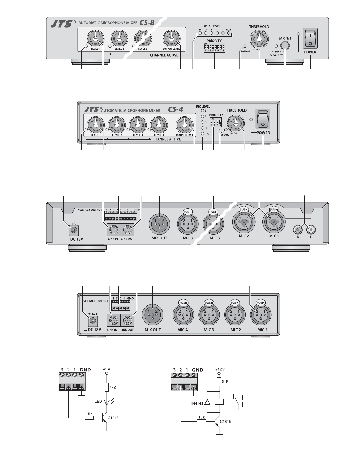
3
10 11 12 13 14 15 16 17
10 11 12 13 14 15
12 3456 79
CS-8
CS-4
12 345 67 8 9
Page 4
Auf der ausklappbaren Seite 3 finden Sie
alle beschriebenen Bedienelemente und An schlüsse.
1 Übersicht der Bedien elemen te
und Anschlüsse
1.1 Vorderseite
1 Status-LED für jeden Eingang; leuchtet,
wenn der Eingangskanal eingeschaltet ist
2 Lautstärkeregler LEVEL für jeden Eingangs-
kanal
3 Regler OUTPUT LEVEL für die Gesamtlaut-
stärke
4 LED-Anzeige für den Gesamtpegel vor dem
Regler OUTPUT LEVEL
5 Vorrangschalter PRIORITY für jeden Ein-
gangskanal (
Ka pitel 7.1.1)
6 LED LOCKOUT; leuchtet, wenn im Automa-
tik-Modus der Pegel eines Eingangssignals
den eingestellten Schwellwert überschreitet
7 Regler THRESHOLD zum Einstellen des
Schwellwertes für den Pegel eines Eingangssignals zur automatischen Kanalumschaltung
Wird der Regler am Linksanschlag eingerastet
(BYPASS), ist die Mischautomatik ausgeschaltet. Das Mischverhältnis aller Kanäle
kann manuell mit den Reglern LEVEL (2) eingestellt werden.
8 nur CS-8: Taste MIC1/2
Umschalter für die Betriebsart der Eingänge
MIC 1 und MIC 2
Taste hineingedrückt „Common“ (die LED
neben der Taste leuchtet):
die Signale der beiden Kanäle können nicht
die anderen Kanäle ausschließen (geeignet
z. B. für Hintergrundmusik)
Taste ausgerastet „Normal“: die beiden
Kanäle verhalten sich wie die übrigen Ka näle
9 Ein-/Ausschalter POWER mit Betriebsan-
zeige
1.2 Rückseite
10 Stromversorgungsbuchse zum Anschluss des
beiliegenden Netzgeräts
11 Buchse LINK IN zum Anschluss an die
Buchse LINK OUT (13) eines anderen CS-4
oder CS-8 über das mitgelieferte Verbindungskabel als Erweiterung eines Gerätes,
wenn zusätzliche Eingänge be nötigt werden
12 Schraubklemmen für die Bereitstellung einer
Steuerspannung entsprechend der StatusLED (1) für jeden Eingangskanal (
Ka pitel
5.4)
13 Buchse LINK OUT zum Anschluss an die
Buchse LINK IN (11) eines anderen CS-4/
CS-8 über das mitgelieferte Verbindungskabel, wenn zusätzliche Eingänge benötigt werden
14 XLR-Ausgang MIX OUT für das Mischsignal
zum An schluss an einen Mikrofoneingang
oder Line-Eingang z. B. eines Mischpults
oder Verstärkers
15 XLR-Buchsen zum Anschluss von Mikrofo-
nen oder Geräten mit Line-Ausgangspegel
für die Eingangskanäle MIC 1 – MIC4 (CS-4)
bzw. MIC3– MIC8 (CS-8)
16 nur CS-8: kombinierte XLR-/6,3-mm-Klinken-
Buchsen zum Anschluss von Mikrofonen oder
Geräten mit Line-Ausgangspegel für die Eingangskanäle MIC 1 und MIC 2
17 nur CS-8: Cinch-Buchsen zum Anschluss
von (Stereo-)Geräten an die Eingangskanäle
MIC 1 und MIC 2, alternativ zu den kombinierten Buchsen (16) [intern umschaltbar]
2 Hinweise für den sicheren
Gebrauch
Die Geräte (Mischer und Netzgerät) entsprechen allen relevanten Richtlinien der EU und
sind deshalb mit gekennzeichnet.
Beachten Sie auch unbedingt folgende Punkte:
G
Die Geräte sind nur zur Verwendung im Innenbereich geeignet. Schützen Sie sie vor Tropfund Spritzwasser, hoher Luftfeuchtigkeit und
Hitze (zulässiger Einsatztemperaturbereich
0–40°C).
G
Nehmen Sie den Mischer nicht in Betrieb und
ziehen Sie sofort das Netzgerät aus der Steckdose,
1. wenn sichtbare Schäden an den Geräten
vorhanden sind,
2. wenn nach einem Sturz oder Ähnlichem der
Verdacht auf einen Defekt besteht,
3. wenn Funktionsstörungen auftreten.
Geben Sie die Geräte in jedem Fall zur Reparatur in eine Fachwerkstatt.
G
Verwenden Sie für die Reinigung nur ein trockenes, weiches Tuch, niemals Wasser oder
Chemikalien.
G
Werden die Geräte zweckentfremdet, nicht
richtig angeschlossen, falsch bedient oder
nicht fachgerecht repariert, kann keine Haftung für daraus resultierende Sach- oder Personenschäden und keine Garantie für die
Geräte übernommen werden.
3 Einsatzmöglichkeiten
Die automatischen Mikrofonmischer CS-4 und
CS-8 sind optimale Werkzeuge bei der elektroakustischen Verstärkung von Konferenzen oder
Diskussionsrunden. Sie minimieren elegant die
Probleme, die mit dem gleichzeitigen Einsatz
mehrerer Mikrofone verbunden sind, wie z. B.
schlechte Sprachverständlichkeit durch Hintergrundgeräusche, Kammfiltereffekte und Rückkopplungsneigung, indem immer nur ein Mikrofon zurzeit eingeschaltet wird. Dabei bleibt das
zuletzt genutzte Mikrofon immer eingeschaltet.
So entsteht keine plötzliche Stille, wie es durch
das abrupte Ausbleiben der Hintergrundgeräusche beim Abschalten des Kanals der Fall wäre.
Durch eine Vorrangoption für jeden Kanal kann
z. B. der Konferenzleiter jederzeit ein Gespräch
übernehmen.
Der CS-4 bietet vier Eingangskanäle, der
CS-8 acht, von denen beim CS-8 zwei alternativ
zur Einspielung von Hintergrundmusik genutzt
werden können. Alle Eingänge können sowohl
mit Mikrofonpegeln als auch mit Line-Pegeln
gespeist werden, eine Phantomspannung ist
einzeln schaltbar.
Für jeden Kanal wird zudem eine Steuerspannung bereitgestellt, mit der sich z. B. eine
Anzeige zum Kanalstatus realisieren lässt. Über
ein beiliegendes Kabel lassen sich zur Erhöhung der Kanalzahl mehrere Mikrofonmischer
koppeln.
Die Mischautomatik ist abschaltbar, sodass
sich die Mischer auch manuell nutzen lassen.
4 Rackmontage
Der Mikrofonmischer kann als Tischgerät verwendet oder in ein Rack für Geräte mit einer
Breite von 482 mm (19″) eingebaut werden. Da
es für einige Grundeinstellungen erforderlich ist,
das Gerät zu öffnen, sollte der Einbau erst nach
einem Probebetrieb und sich daraus ergebenden Voreinstellungen erfolgen. Für den Rack einbau die vier Standfüße abschrauben (nur
beim CS-8 erforderlich) und die beiden beiliegenden Montagewinkel links und rechts am
Mischer festschrauben.
5 Anschluss
5.1 Signalquellen
Mikrofone und Signalquellen mit Line-Ausgangspegel (z. B. Vorverstärker, Mischpulte) an
die Buchsen MIC 1 – 4 [CS-4] (15) bzw.
MIC 1 – 8 [CS-8] (15, 16) anschließen. Die XLRBuchsen sind symmetrisch beschaltet. Für den
Anschluss einer Signalquelle mit asymmetrischem Signal einen Adapter verwenden, bei
dem die XLR-Kontakte 1 und 3 gebrückt sind.
Beim CS-8 können an die kombinierten
Buchsen (16) der Kanäle 1 und 2 alternativ
6,3-mm-Klinkenstecker angeschlossen wer den.
Die Klinkenbuchsen sind ebenfalls symmetrisch
beschaltet. Die Verbindung mit asymmetrischen
Ausgängen kann hier einfach durch 2-polige
Klinkenstecker erfolgen. Alternativ kön nen
asymmetrische Signale über die beiden CinchBuchsen R/ L (17) zugeführt werden (z. B. das
Stereo-Signal eines CD-Spielers für das Abspielen von Hintergrundmusik). Da der CS-8 monofon arbeitet, wird aus einem Stereosignal intern
ein Monosignal gemischt. Das Umschalten zwischen den alternativen Buchsen muss im Geräte innern vorgenommen werden (
Ka pitel 6.2).
Zum späteren Herausziehen eines XLR-Steckers den PUSH-Hebel an der Buchse drücken.
5.2 Verstärker oder Mischpult
Den Ausgang MIX OUT (14) mit dem Mikrofoneingang oder Line-Eingang z. B. eines Mischpults oder Verstärkers verbinden. Der Ausgang
liefert ein symmetrisches Signal, dessen Pegel
(Mikrofon/ Line) zur Anpassung an das nachfolgende Gerät im Innern des Mischers umgeschaltet werden kann (Ka pitel 6.5).
5.3 Mikrofonmischer koppeln
Sollte die Anzahl der Eingangskanäle eines
Mischers nicht ausreichen, so lassen sich mehrere Geräte koppeln. Sie funktionieren dann
zusammen wie ein Mischer. Dies ist auch zwischen den Modellen CS-4 und CS-8 möglich.
Zum Zusammenschalten der Geräte:
1) Den Ausgang LINK OUT (13) des ersten
Geräts über das beiliegende Kabel mit dem
Eingang LINK IN (11) des zweiten Geräts
verbinden.
2) Bei zusätzlichem Bedarf den Ausgang LINK
OUT des zweiten Geräts mit dem Eingang
LINK IN eines weiteren Geräts verbinden,
Sollen die Geräte endgültig aus dem
Betrieb genommen werden, übergeben
Sie sie zur umweltgerechten Entsorgung einem örtlichen Recyclingbetrieb.
WARNUNG Das Netzgerät wird mit lebens -
gefährlicher Netzspannung versorgt. Nehmen Sie deshalb niemals selbst Eingriffe daran vor.
Durch unsachgemäßes Vorgehen
besteht die Gefahr eines elektrischen Schlages.
4
DEUTSCH
Page 5

usw., bis alle Geräte in einer Kette verbunden
sind.
3) Das Mischsignal aller Geräte steht am Ausgang (14) des letzten Geräts der Kette zur
Verfügung. Diesen Ausgang mit dem Mikrofoneingang oder Line-Eingang z. B. eines
Mischpults oder Verstärkers verbinden (vgl.
Ka pitel 5.2).
5.4 Andere Geräte steuern
Der Status „ein“ oder „aus“ wird für jeden Eingangskanal mit einer LED (1) angezeigt. Um in
Abhängigkeit des Status z. B. eine Betriebsanzeige am Mikrofon steuern zu können, steht an
der Klemmenleiste VOLTAGE OUTPUT (12) für
jeden Kanal eine Steuerspannung zur Verfügung. Diese beträgt ca. +4 V bei eingeschaltetem Kanal und 0 V im Zustand „aus“ (jeweils an
der Klemme mit der Nummer des Kanals bezogen auf die gemeinsame Klemme GND).
Auf Seite 3 sind zwei Beispielschaltungen
gezeigt, wie die Steuerspannung für die An steuerung einer Leuchtdiode (Abb. 5) oder eines
12-V-Relais (zum Schalten größerer Lasten,
Abb. 6) genutzt werden kann.
5.5 Netzanschluss
Das beiliegende Netzgerät mit der Stromversorgungsbuchse (10) verbinden und in eine Steckdose (230 V~/50 Hz) stecken.
6 Voreinstellungen
Für folgende Voreinstellungen (Kapitel 6.1 bis
6.5) muss das Gerät geöffnet werden.
1) Vor dem Öffnen des Gerätes unbedingt das
Gerät von der Stromversorgung trennen!
2) Die Schrauben des Gehäusedeckels entfer-
nen und den Deckel abnehmen.
3) Die Einstellungen mithilfe der Schiebeschal-
ter vornehmen. Die Zeichnungen auf der vorletzten Seite dieser Anleitung bieten einen
Überblick über die Lage der Schalter und
deren Funktionen, die im Folgenden be schrieben werden.
4) Nach dem Durchführen der Einstellungen
den Deckel wieder befestigen und die Stromversorgung wiederherstellen.
6.1 Phantomspeisung
Für Mikrofone, die eine Phantomspeisung benötigen, kann für jeden Eingang separat eine
Phantomspannung von 12 V (CS-4) bzw. 48V
(CS-8) eingeschaltet werden. Dazu den Schalter
PHANTOM Ⓐ des entsprechenden Kanals in
die Position „+12V“ bzw. „+48V“ stellen.
Wichtig: Beim Anschluss von Mikrofonen oder
anderen Signalquellen mit asymmetrisch be schaltetem Ausgang muss die Phantomspeisung
ausgeschaltet werden (Position „OFF“), da diese
Geräte sonst be schädigt werden können.
6.2 Anschlussalternativen (nur CS-8)
Für die Kanäle MIC 1 und MIC2 kann beim CS-8
jeweils gewählt werden, ob die Cinch-Buchse
oder die kombinierte XLR-/Klinken-Buchse als
Eingang dienen soll. Dazu den entsprechenden
Schalter Ⓑin die gewünschte Position stellen.
„RCA“ = Cinch-Buchse
„MIC“ = kombinierte XLR-/Klinken-Buchse
Wichtig: Bei der Verwendung der Cinch-Buchse
muss die Phantomspeisung für diesen Eingang
unbedingt ausgeschaltet werden (
Ka pitel 6.1).
6.3 Eingangsempfindlichkeit
Der Schalter INPUT ATT Ⓒdient dazu, die Eingangsempfindlichkeit des jeweiligen Eingangs
auf die verwendete Signalquelle einzustellen.
Beim Anschluss eines Mikrofons den Schalter in
die Position „MIC 0 dB“ stellen, beim Anschluss
einer Signalquelle mit Line-Ausgangspegel in
die Position „LINE
-
50 dB“.
Eine Feineinstellung der Empfindlichkeit
kann jeweils mithilfe des Schalters PAD (CS-4)
bzw. MIC IN ATT (CS-8) Ⓓ vorgenommen werden. Hier lässt sich der Pegel zusätzlich um
5 dB (nur CS-8) oder 10 dB dämpfen.
6.4 „Aus“-Dämpfung
Wird ein Mikrofonsignal im Automatik-Modus
durch das Signal eines anderen Eingangskanals
„ausgesperrt“, so wird das Mikrofon nicht ganz
ausgeschaltet, sondern nur leiser geregelt.
Wie stark die Signaldämpfung im „Aus“Zustand eines jeden Eingangskanals sein soll,
wird mit dem Schalter MIC ATT Ⓔ be stimmt (10,
15 oder 20 dB Dämpfung).
Wird eine größere Anzahl Mikrofone verwendet, so empfiehlt es sich, eine höhere Dämpfung
einzustellen, um den Hintergrundgeräuschpegel
zu reduzieren und damit eine bessere Sprachverständlichkeit zu erreichen. Ebenso verringert
sich bei höherer Dämpfung die Gefahr einer
Rückkopplung.
6.5 Ausgangspegel
Mit dem Schalter OUTPUT ATT Ⓕ kann der Ausgangspegel an den Eingang des nachfolgenden
Audiogeräts angepasst werden.
Beim Anschluss an einen Mikrofoneingang
den Schalter in die Position „MIC
-
50 dB“ stellen, beim Anschluss an einen Line-Eingang in
die Position „LINE 0 dB“.
7 Bedienung
Den Regler OUTPUT LEVEL (3) vor dem ersten
Betrieb auf Minimum (Linksanschlag) drehen.
Den Mikrofonmischer mit dem Schalter POWER
(9) einschalten; die LED neben dem Schalter
leuchtet. Die Status-LEDs (1) der Eingänge
leuchten nacheinander kurz auf.
7.1 Automatik-Modus
Im Automatik-Modus schaltet der Mikrofonmischer in Abhängigkeit von den Eingangssignalen die Mikrofonkanäle ein und aus (aus = ge dämpft
Ka pitel 6.4). Sobald die Lautstärke
eines Mikrofons den eingestellten Schwellwert
überschreitet, wird dieser Kanal eingeschaltet,
während alle anderen Kanäle ausgeschaltet
bleiben. Sobald die Lautstärke des eingeschalteten Mikrofons unter den Schwellwert fällt, kann
das Mikrofon durch ein anderes Mikrofon mit
entsprechend hoher Lautstärke abgelöst werden. Dadurch wird das erste Mikrofon „ausgeschlossen“, es bleibt immer nur ein Kanal eingeschaltet (Ausnahme bei Kanälen mit Vorrang
Ka pitel 7.1.1).
Zum Einrichten des Automatik-Modus:
1) Den Regler THRESHOLD (7) soweit nach
links drehen, dass er gerade noch nicht einrastet. Damit ist der minimale Schwellwert
eingestellt.
2) Zunächst alle Regler LEVEL (2) auf Minimum
(Linksanschlag) und alle PRIORITY-Schalter
(5) in die untere Position stellen.
3) Die am Ausgang angeschlossene Verstärker-
anlage einschalten und den Regler OUTPUT
LEVEL (3) etwas aufdrehen, so dass die
nachfolgenden Einstellungen zu hören sind.
4) In ein Mikrofon sprechen und den Regler
LEVEL des entsprechenden Kanals soweit
aufdrehen, dass die LED LOCKOUT (6) bei
normal lauter Sprache aufleuchtet. Diese
zeigt an, dass der eingestellte Schwellwert
überschritten und der Mikrofonkanal eingeschaltet wird. Solange der Kanal eingeschaltet ist, leuchtet seine Status-LED (1).
Den Regler LEVEL nur soweit aufdrehen,
dass die LED „6“ in der Anzeige MIX LEVEL
(4) nur bei Signalspitzen leuchtet. Leuchtet
sie ständig oder sogar die LED „Peak“ (nur
beim CS-8), ist der Mischer übersteuert und
das Ausgangssignal verzerrt.
Ist der Pegel zu groß oder zu klein, um
mit dem Regler LEVEL richtig eingestellt zu
werden, ggf. die Einstellung für die Eingangsempfindlichkeit korrigieren (
Ka pitel 6.3).
5) Die anderen Eingangskanäle auf die gleiche
Weise einstellen.
6) Mit dem Regler OUTPUT LEVEL den Ausgangspegel des Mischers so einstellen, dass
das nachfolgende Gerät nicht übersteuert
wird.
7) Werden Mikrofone versehentlich schon
durch laute Hintergrundgeräusche eingeschaltet, mit dem Regler THRESHOLD einen
höheren Schwellwert einstellen.
7.1.1 Vorrangschaltung
Soll ein Mikrofon vor anderen Vorrang erhalten
(z. B. das Mikrofon des Vorsitzenden), den entsprechenden PRIORITY-Schalter (5) in die
obere Position „ON“ stellen.
Der Sprecher an diesem Mikrofon kann
jederzeit das Gespräch übernehmen. Das
Mikrofon wird eingeschaltet, sobald die Lautstärke den Schwellwert überschreitet, unabhängig davon, ob gerade in ein anderes Mikrofon
gesprochen wird.
Ist für mehrere Kanäle der Vorrang gewählt,
lassen sich diese gleichzeitig nutzen.
7.1.2 Betriebsart der Kanäle 1 und 2
(nur CS-8)
Beim CS-8 kann für die Eingangskanäle 1 und 2
mithilfe der Taste MIC 1/2 (8) zwischen zwei
Betriebsarten gewählt werden:
„Common“ (Taste hineingedrückt, die LED ne ben der Taste leuchtet):
Die Signale der beiden Kanäle können nicht die
anderen Kanäle ausschließen, sie werden aber
gedämpft, sobald das Signal auf einem anderen
Kanal den Schwellwert überschreitet. Diese
Betriebsart eignet sich z. B. für die Einspielung
von Hintergrundmusik.
„Normal“ (Taste ausgerastet, LED aus):
Die beiden Kanäle verhalten sich wie die übrigen Kanäle.
7.2 Manuelles Mischen
Wird der Regler THRESHOLD (7) bis zum
Linksanschlag gedreht, sodass er in der Position
„BYPASS“ einrastet, ist die Mischautomatik
deaktiviert. Es sind jetzt alle Eingangskanäle
eingeschaltet. Sie können mit ihren LEVEL-Reglern (2) manuell gemischt werden. Mit dem Regler OUTPUT LEVEL (3) kann die Gesamtlautstärke eingestellt werden.
Auch beim manuellen Mischen sollte die
Anzeige MIX LEVEL (4) beachtet werden. Sie
zeigt den Pegel vor dem Regler OUTPUT
LEVEL an. Ist der Mischpegel zu hoch (LEDs „6“
oder „Peak“ leuchten häufig), müssen die
5
DEUTSCH
Page 6

LEVEL-Regler der entsprechenden Kanäle zu rückgedreht werden.
7.3 Gekoppelte Mikrofonmischer
Sind zwei oder mehrere Mikrofonmischer über
die Buchsen LINK IN (11) und LINK OUT (13)
miteinander verbunden, so wirken sie zusammen wie ein großer Mischer. Dabei liegen am
Ausgang MIX OUT (14) eines Gerätes die
Mischsignale der gesamten über die Buchse
LINK IN angeschlossenen Gerätekette. Die
Mischsignale werden jeweils vor dem Regler
OUTPUT LEVEL (3) weitergeleitet, so dass über
ihn nur der Pegel für den eigenen Ausgang MIX
OUT eingestellt werden kann.
Der Schwellwert für den Automatik-Modus
lässt sich an jedem Mischer individuell für seine
Eingänge einstellen. Die LED LOCKOUT (6)
leuchtet bei Überschreiten eines Schwellwertes
immer an allen verbundenen Geräten auf. Wird
bei einem der Mischer die Automatik deaktiviert
(BYPASS), beeinflusst dies nicht die AutomatikFunktion der anderen verbundenen Mischer.
8 Technische Daten
Frequenzbereich: . . . . . . . . 35– 20 000 Hz
Klirrfaktor: . . . . . . . . . . . . . . < 0,06 %
Störabstand: . . . . . . . . . . . . > 70 dB
Eingänge (Empfindlichkeit/ Impedanz)
Mikrofon: . . . . . . . . . . . . . 0,2 mV/ 4,7 kΩ
Line: . . . . . . . . . . . . . . . . . 60 mV/ 20 kΩ
Phantomspeisung (einzeln schaltbar)
CS-4: . . . . . . . . . . . . . . . . +12 V
CS-8: . . . . . . . . . . . . . . . . +48 V
Ausgang MIX OUT
Nennausgangsspannung: 1 V
Ausgangsimpedanz: . . . . 200 Ω
Kontaktbelegung
XLR-Anschlüsse
6,3-mm-Klinkenanschluss
Steuerausgänge: . . . . . . . . . 0 V/+4V (aus/ein)
Stromversorgung: . . . . . . . . über beiliegendes
Steckernetzgerät
an 230 V~/50 Hz
Einsatztemperatur: . . . . . . . 0 – 40 °C
Abmessungen
CS-4: . . . . . . . . . . . . . . . . 200 ×44 ×212mm
(1 HE)
CS-8: . . . . . . . . . . . . . . . . 420 ×44 ×199mm
(1 HE)
Gewicht
CS-4: . . . . . . . . . . . . . . . . 1,4 kg
CS-8: . . . . . . . . . . . . . . . . 2,3 kg
Änderungen vorbehalten.
T = Signal +
R = Signal
-
S = Masse
1 = Masse
2 = Signal +
3 = Signal
-
6
DEUTSCH
Diese Bedienungsanleitung ist urheberrechtlich für MONACOR®INTERNATIONAL GmbH & Co. KG
geschützt. Eine Reproduktion für eigene kommerzielle Zwecke – auch auszugsweise – ist untersagt.
Page 7
All operating elements and connections de scribed can be found on the fold-out page 3.
1 Operating Elements
and Connections
1.1 Front side
1 Status LED for each input; lights up when the
input channel is switched on
2 LEVEL control for each input channel
3 OUTPUT LEVEL control for the overall vol-
ume
4 LED indication for the overall level ahead of
the OUTPUT LEVEL control
5 PRIORITY switch for each input channel
(
chapter 7.1.1)
6 LED LOCKOUT; lights up when in the auto-
matic mode the level of an input signal
exceeds the adjusted threshold value
7 Control THRESHOLD to adjust the threshold
value for the level of an input signal for automatic channel switching
If the control is engaged at the left stop
(BYPASS), the automatic mixing feature is
deactivated. The mixing ratio of all channels
may manually be adjusted with the LEVEL
controls (2).
8 CS-8 only: button MIC 1/2
Selector switch for the operating mode of the
inputs MIC 1 and MIC2
Button engaged “Common” (the LED next to
the button lights up):
The signals of both channels are not able to
lock out the other channels (suitable e. g. for
background music)
Button disengaged “Normal”: both channels
act like the other channels
9 POWER switch with power LED
1.2 Rear side
10 Power supply jack for connection of the
power supply unit provided
11 Jack LINK IN for connection to the jack LINK
OUT (13) of another CS-4 or CS-8 via the
supplied connection cable as an extension of
a unit when additional inputs are necessary
12 Screw terminals for providing a control volt-
age for each input channel according to the
status LED (1) [
chapter 5.4]
13 Jack LINK OUT for connection to the jack
LINK IN (11) of another CS-4 / CS-8 via the
connection cable provided when additional
inputs are necessary
14 XLR output MIX OUT for the mixed signal for
connection to a microphone input or line input
e. g. of a mixer or amplifier
15 XLR jacks for connection of microphones or
units with line output level for the input channels MIC 1 to MIC 4 (CS-4) or MIC 3 to MIC8
(CS-8)
16 CS-8 only: combined XLR / 6.3 mm jacks for
connection of microphones or units with line
output level for the input channels MIC 1 and
MIC 2
17 CS-8 only: RCA jacks for connection of
(stereo) units to the input channels MIC 1 and
MIC 2, alternatively to the combined jacks
(16) [internally switchable]
2 Safety Notes
The units (mixer and power supply unit) correspond to all relevant directives of the EU and are
therefore marked with .
It is essential to observe the following items:
G
The units are suitable for indoor use only. Protect them against dripping water and splash
water, high air humidity and heat (admissible
ambient temperature range 0 – 40 °C).
G
Do not set the mixer into operation, and immediately disconnect the power supply unit from
the mains socket if
1. there is visible damage to the units,
2. a defect might have occurred after a drop or
similar accident,
3. malfunctions occur.
The units must in any case be repaired by
skilled personnel.
G
For cleaning only use a dry, soft cloth, never
use chemicals or water.
G
No guarantee claims for the units and no liability for any resulting personal damage or material damage will be accepted if the units are
used for other purposes than originally
intended, if they are not correctly connected or
operated, or not repaired in an expert way.
3 Applications
The automatic microphone mixers CS-4 and
CS-8 are optimum tools for the electroacoustic
amplification of conferences or discussion meetings. They minimize in an elegant way the problems linked with the simultaneous use of several
microphones, e. g. poor speech intelligibility
caused by background noise, comb filter effects
and tendency to feedback, by switching on one
microphone only at a time. Then the last microphone used always remains switched on. Thus,
there is no sudden silence as it would occur if
the background noise suddenly stopped when
switching off the channel. By a priority option for
each channel, e. g. the chairperson of the conference is able to take over a conversation at
any time.
The CS-4 offers four input channels, the
CS-8 offers eight input channels of which two
can alternatively be used for inserting background music. All inputs may be fed both with
microphone levels and line levels, a phantom
voltage can individually be activated.
In addition, a control voltage is provided for
each channel by which e. g. the channel status
can be indicated. Via a supplied cable, several
microphone mixers may be coupled to increase
the number of channels.
The automatic mixing feature can be deactivated so that the mixers can also be used manually.
4 Rack mounting
The microphone mixer can be used as a table
top unit or be installed into a rack for units with a
width of 482 mm (19″). As it is necessary to
open the unit for some basic settings, the installation should only be made after a trial operation
and the preadjustments resulting from it. For
rack installation unscrew the four feet at the
base (required for CS-8 only) and fasten the two
supplied mounting brackets at the left and right
of the mixer.
5 Connection
5.1 Signal sources
Connect microphones and signal sources with
line output level (e. g. preamplifiers, mixers) to
the jacks MIC 1 to 4 [CS-4] (15) or MIC 1 to 8
[CS-8] (15, 16). The XLR jacks are balanced. To
connect a signal source with unbalanced signal,
use an adapter with the XLR contacts 1 and 3
bridged.
CS-8: alternatively, 6.3mm plugs may be
connected to the combined jacks (16) of the
channels 1 and 2. The 6.3 mm jacks are likewise
balanced. The connection with unbalanced outputs can easily be made by 2-pole 6.3 mm plugs.
Alternatively, unbalanced signals may be fed via
the two RCA jacks R / L (17) [e. g. the stereo signal of a CD player for playing background
music]. As the CS-8 operates in a monophonic
way, a mono signal is internally mixed from a
stereo signal. The alternative jacks are switched
over inside the unit (
chapter 6.2).
To remove an XLR plug later, press the
PUSH lever at the jack.
5.2 Amplifier or mixer
Connect the output MIX OUT (14) to the microphone input or line input e. g. of a mixer or amplifier. The output supplies a balanced signal
whose level (microphone / line) may be switched
over inside the mixer for adaptation to the following unit (
chapter 6.5).
5.3 Coupling the microphone mixers
If the number of input channels of a mixer should
not be sufficient, it is possible to couple several
units. Together they operate like one mixer. This
is also possible for the models CS-4 and CS-8.
To interconnect the units:
1) Connect the output LINK OUT (13) of the first
unit via the supplied cable to the input LINK
IN (11) of the second unit.
2) For additional requirement, connect the out-
put LINK OUT of the second unit to the input
LINK IN of another unit etc. until all units are
connected in a chain.
3) The mixed signal of all units is available at
the output (14) of the last unit of the chain.
Connect this output to the microphone input
or line input e. g. of a mixer or amplifier (compare chapter 5.2).
5.4 Controlling other units
The status “on” or “off” for each input channel is
shown by an LED (1). To be able to control e. g.
an operating indication at the microphone
depending on the status, a control voltage for
each channel is available at the terminal strip
VOLTAGE OUTPUT (12). This voltage is
approx. +4 V with the channel switched on and
If the units are to be put out of operation
definitively, take them to a local recycling plant for a disposal which is not
harmful to the environment.
WARNING The power supply unit is supplied
with hazardous mains voltage.
Leave servicing to skilled personnel only. Inexpert handling or
modification of the unit may cause
an electric shock hazard.
7
ENGLISH
Page 8

0 V in “off” condition (each at the terminal with
the number of the channel referring to the common terminal GND).
On page 3, two circuits of example show
how to use the control voltage for driving a lightemitting diode (fig. 5) or a 12 V relay (to switch
higher loads, fig. 6).
5.5 Mains connection
Connect the power supply unit provided to the
power supply jack (10) and to a socket (230 V~ /
50 Hz).
6 Preadjustments
The unit must be opened for the following preadjustments (chapter 6.1 to chapter 6.5).
1) Prior to opening the unit always disconnect
the unit from the power supply!
2) Remove the screws of the housing cover and
the cover.
3) Make the adjustments by means of the slid-
ing switches. The drawings on the last but
one page of these instructions present an
overview over the position of the switches
and their functions described below.
4) After the adjustments have been completed,
fasten the cover and re-establish the power
supply.
6.1 Phantom power
For microphones requiring a phantom power, a
phantom voltage of 12 V (CS-4) or 48 V (CS-8)
may be switched on separately for each input.
For this purpose, set the switch PHANTOM Ⓐ of
the corresponding channel to the position
“+12V” or “+48V”.
Important: When connecting microphones or
other signal sources with unbalanced output, the
phantom power must be switched off (position
“OFF”) as these units may be damaged.
6.2 Alternatives of connection
(CS-8 only)
For CS-8: It is possible to define in each case for
the channels MIC 1 and MIC 2 if the RCA jack or
the combined XLR / 6.3 mm jack is to serve as an
input. For this purpose set the corresponding
switch Ⓑ to the desired position.
“RCA”= RCA jack
“MIC” = combined XLR / 6.3 mm jack
Important: When using the RCA jack, the phantom power for this input must always be
switched off (
chapter 6.1).
6.3 Input sensitivity
The switch INPUT ATT Ⓒ serves to adjust the
input sensitivity of the respective input to the signal source used. When connecting a microphone, set the switch to the position “MIC 0 dB”,
when connecting a signal source with line output
level, set the switch to position “LINE
-
50 dB”.
The fine adjustment of the sensitivity can be
made in each case with the switch PAD (CS-4)
or MIC IN ATT (CS-8) Ⓓ. Here the level can
additionally be attenuated by 5 dB (CS-8 only) or
10 dB.
6.4 “Off” attenuation
If in the automatic mode a microphone signal is
“locked out” by the signal of another input channel, the microphone is not completely switched
off but its volume is attenuated to a lower value
only.
By means of the switch MIC ATT Ⓔ the
extent of the signal attenuation is defined in the
“Off” condition of each input channel (attenuation by 10, 15 or 20 dB).
If a larger number of microphones is used, it
is recommended to adjust a higher attenuation
to reduce the background noise level and thus to
obtain a better speech intelligibility. Likewise,
with a higher attenuation, the risk of a feedback
is reduced.
6.5 Output level
The output level can be adapted to the input of
the following audio unit with the switch OUTPUT
ATT Ⓕ.
When connecting a microphone input, set
the switch to position “MIC
-
50 dB”. When connecting a line input, set the switch to position
“LINE 0 dB”.
7 Operation
Prior to the first operation, turn the OUTPUT
LEVEL control (3) to minimum (left stop). Switch
on the microphone mixer with the POWER
switch (9); the LED next to the switch lights up.
The status LEDs (1) of the inputs shortly light up
successively.
7.1 Automatic mode
In the automatic mode, the microphone mixer
switches the microphone channels on and off
depending on the input signals (off = attenuated
chapter 6.4). As soon as the volume of a
microphone exceeds the threshold value
adjusted, this channel is switched on while all
other channels remain switched off. As soon as
the volume of the microphone switched on falls
below the threshold value, the microphone may
be replaced by another microphone of correspondingly high volume. Thus, the first microphone is “locked out”, one channel only always
remains switched on (exception: channels with
priority
chapter 7.1.1).
To establish the automatic mode:
1) Turn the control THRESHOLD (7) so far to
the left that it is not yet engaged. Thus, the
minimum threshold value is adjusted.
2) For the time being set all controls LEVEL (2)
to minimum (left stop) and all PRIORITY
switches (5) to the lower position.
3) Switch on the amplifier system connected to
the output and slightly turn up the OUTPUT
LEVEL control (3) so that the following
adjustments can be heard.
4) Talk into a microphone and turn up the
LEVEL control of the corresponding channel
so that the LED LOCKOUT (6) lights up with
speech at an average volume. This LED indicates that the threshold value adjusted is
exceeded and the microphone channel is
switched on. As long as the channel is
switched on, its status LED (1) lights up.
Turn up the LEVEL control only to such
an extent so that the LED “6” in the indication
MIX LEVEL (4) lights up with signal peaks
only. If it lights up permanently or even the
LED “Peak” (CS-8 only), the mixer is overloaded and the output signal is distorted.
If the level is too high or too low to be correctly adjusted with the LEVEL control, readjust the adjustment for the input sensitivity, if
required (
chapter 6.3).
5) Adjust the other input channels in the same
way.
6) Adjust the output level of the mixer with the
OUTPUT LEVEL control so that the following
unit will not be overloaded.
7) If microphones are accidentally switched on
by loud background noise, adjust a higher
threshold value with the control THRESHOLD.
7.1.1 Priority circuit
If a microphone is to take priority over other
microphones (e. g. the microphone of the chairperson), set the corresponding PRIORITY
switch (5) to the upper position “ON”.
The speaker at this microphone may take
over the conversation at any time. The microphone is switched on as soon as the volume
exceeds the threshold value, regardless of any
other microphone used at this moment.
If priority has been selected for several channels, these channels can be used at the same
time.
7.1.2 Operating mode of channels 1 and 2
(CS-8 only)
For CS-8, two operating modes are available for
the input channels 1 and 2 by means of the button MIC 1/2 (8):
“Common” (button engaged, the LED next to the
button lights up):
The signals of both channels are not able to lock
out the other channels, but they are attenuated
as soon as the signal on another channel
exceeds the threshold value. This operating
mode is e. g. suitable for inserting background
music.
“Normal” (button disengaged, LED off):
Both channels act like the other channels.
7.2 Manual mixing
If the control THRESHOLD (7) is turned to the
left stop so that it engages in position “BYPASS”,
the automatic mixing feature is deactivated. Now
all input channels are switched on. They can
manually be mixed with their LEVEL controls (2).
With the OUTPUT LEVEL control (3), the overall
volume can be adjusted.
For manual mixing, too, the indication MIX
LEVEL (4) should be observed. It shows the
level ahead of the OUTPUT LEVEL control. If
the mixed level is too high (LEDs “6” or “Peak”
light up frequently), the LEVEL controls of the
corresponding channels must be turned back.
7.3 Coupled microphone mixers
If two or several microphone mixers are interconnected via the jacks LINK IN (11) and LINK
OUT (13), they act together like a large mixer.
The mixed signals of the complete chain of units
connected via the jack LINK IN are present at
the output MIX OUT (14) of a unit. The mixed
signals are routed in each case ahead of the
OUTPUT LEVEL control (3) so that it is only possible to adjust the level for the individual output
MIX OUT via this control.
The threshold value for the automatic mode
can be adjusted at each mixer individually for its
inputs. The LED LOCKOUT (6) always lights up
at all units connected when exceeding the
threshold value. If the automatic feature is deactivated at one of the mixers (BYPASS), this does
not affect the automatic feature of the other mixers connected.
8
ENGLISH
Page 9

8 Specifications
Frequency range: . . . . . . . . 35 – 20 000Hz
THD: . . . . . . . . . . . . . . . . . . < 0.06 %
S / N ratio: . . . . . . . . . . . . . . . > 70 dB
Inputs (sensitivity/ impedance)
Microphone: . . . . . . . . . . . 0.2 mV/ 4.7 kΩ
Line: . . . . . . . . . . . . . . . . . 60 mV/ 20 kΩ
Phantom power (individually switchable)
CS-4: . . . . . . . . . . . . . . . . +12 V
CS-8: . . . . . . . . . . . . . . . . +48 V
Output MIX OUT
Rated output voltage: . . . 1 V
Output impedance: . . . . . 200 Ω
Contact configuration
XLR connections
6.3 mm plug
Control outputs: . . . . . . . . . . 0 V/ +4 V (off / on)
Power supply: . . . . . . . . . . . via plug-in power
supply unit provided, connected
to 230 V~/50 Hz
Ambient temperature: . . . . . 0 – 40 °C
Dimensions
CS-4: . . . . . . . . . . . . . . . . 200 ×44 ×212mm
(1 rs)
CS-8: . . . . . . . . . . . . . . . . 420 ×44 ×199mm
(1 rs)
Weight
CS-4: . . . . . . . . . . . . . . . . 1.4 kg
CS-8: . . . . . . . . . . . . . . . . 2.3 kg
Subject to technical modifications.
T = signal +
R = signal
-
S = ground
1 = ground
2 = signal +
3 = signal
-
9
ENGLISH
All rights reserved by MONACOR®INTERNATIONAL GmbH & Co. KG. No part of this instruction
manual may be reproduced in any form or by any means for any commercial use.
Page 10
Vous trouverez page 3, dépliable, tous les
éléments et branchements.
1 Eléments et branchements
1.1 Face avant
1 LED dʼétat pour chaque entrée ; brille lors-
quʼun canal dʼentrée est activé
2 Potentiomètres de réglage de volume LEVEL
pour chaque canal dʼentrée
3 Réglage OUTPUT LEVEL pour le volume
général
4 Affichage à LEDs pour le niveau général
avant le réglage OUTPUT LEVEL
5 Interrupteur de priorité PRIORITY pour
chaque canal dʼentrée (
chapitre 7.1.1)
6 LED LOCKOUT; brille lorsque, en mode
automatique, le niveau dʼun signal dʼentrée
dépasse le seuil réglé.
7 Réglage THRESHOLD pour régler le seuil du
niveau dʼun signal dʼentrée pour la commutation automatique des canaux
Si le réglage est enclenché à la butée de
gauche (BYPASS), le mixage automatique
est désactivé. Le rapport de mixage de tous
les canaux peut être réglé manuellement
avec les réglages LEVEL (2).
8 Uniquement CS-8 : Touche MIC1/2
Sélecteur pour le mode de fonctionnement
des entrées MIC 1 et MIC 2
Touche enfoncée “Common” (la LED à côté
de la touche brille) :
les signaux des deux canaux ne peuvent pas
exclure les autres canaux (adapté par
exemple pour une musique dʼambiance)
Touche non enfoncée “Normal” : les deux
canaux se comportent comment les autres
canaux
9 Interrupteur marche / arrêt POWER avec té -
moin de fonctionnement
1.2 Face arrière
10 Prise dʼalimentation pour brancher le bloc
secteur livré
11 Prise LINK IN pour brancher à la prise LINK
OUT (13) dʼun autre CS- 4 ou CS- 8 via le cordon de liaison livré pour compléter un appareil si des entrées supplémentaires sont
nécessaires
12 Bornes à vis pour la tension de commande
selon la LED dʼétat (1) pour chaque canal
dʼentrée (
chapitre 5.4)
13 Prise LINK OUT pour brancher à la prise
LINK IN (11) dʼun autre CS- 4 / CS- 8 via le cordon de liaison livré si des entrées supplémentaires sont nécessaires.
14 Sortie XLR MIX OUT pour le signal de
mixage pour brancher à une entrée micro ou
une entrée ligne, par exemple dʼune table de
mixage ou dʼun amplificateur
15 Prises XLR pour brancher des microphones
ou appareils avec niveau de sortie ligne pour
les canaux dʼentrée MIC 1 – MIC 4 (CS-4) ou
MIC 3 – MIC 8 (CS-8)
16 Uniquement CS-8 : prises combinées XLR /
jack 6,35 femelles pour brancher des microphones ou appareils avec niveau de sortie
ligne pour les canaux dʼentrée MIC 1 et MIC2
17 Uniquement CS-8 : prises RCA pour bran-
cher des appareils (stéréo) aux canaux dʼentrée MIC 1 ou MIC 2, à la place des prises
combinées (16) [commutables en interne].
2 Conseils dʼutilisation
et de sécurité
Les appareils (mixeur et bloc secteur) répondent
à toutes les directives nécessaires de lʼUnion
européenne et portent donc le symbole .
Respectez scrupuleusement les points suivants :
G
Les appareils ne sont conçus que pour une
utilisation en intérieur. Protégez-les de tout
type de projections dʼeau, des éclaboussures,
dʼune humidité de lʼair élevée et de la chaleur
(plage de température de fonctionnement
autorisée : 0 – 40 °C).
G
Ne faites pas fonctionner le mixeur ou débranchez immédiatement le bloc secteur du secteur lorsque :
1. des dommages visibles apparaissent sur
les appareils,
2. après une chute ou un cas similaire, vous
avez un doute sur lʼétat de lʼappareil,
3. des défaillances apparaissent.
Dans tous les cas, les dommages doivent être
réparés par un technicien spécialisé.
G
Pour les nettoyer, utilisez uniquement un chiffon sec et doux, en aucun cas, de produits chimiques ou dʼeau.
G
Nous déclinons toute responsabilité en cas de
dommages matériels ou corporels consécutifs
si les appareils sont utilisés dans un but autre
que celui pour lequel ils ont été conçus, sʼils
ne sont pas correctement branchés ou utilisés
ou sʼils ne sont pas réparés par une personne
habilitée ; de même, la garantie deviendrait
caduque.
3 Possibilités dʼutilisation
Les mixeurs automatiques de microphones
CS-4 et CS-8 sont des outils optima pour lʼamplification électro-acoustique de conférences et
de discussions. Ils minimisent avec élégance les
problèmes liés à lʼutilisation simultanée de plusieurs microphones par exemple une mauvaise
compréhension des propos à cause de bruits de
fonds, dʼeffets de filtres en peigne et la tendance
à des effets larsen dans la mesure où seul un
micro est allumé actuellement. Le dernier micro
utilisé reste toujours allumé. Ainsi il nʼy a pas de
silence soudain, comme cela serait le cas si le
bruit de fonds sʼarrêtait lors de la déconnexion
du canal. Par la fonction de priorité pour chaque
canal, le directeur de la conférence peut par
exemple à tout moment assumer une discussion.
Le CS-4 a quatre canaux dʼentrée, le CS-8
huit canaux, dont deux, sur le CS-8 peuvent
alternativement être utilisés pour de la musique
dʼambiance. Toutes les entrées peuvent être alimentées avec des niveaux micro et des niveaux
ligne, une alimentation fantôme est commutable
séparément.
Pour chaque canal, une tension de commande est mise à disposition avec laquelle par
exemple, on peut visualiser lʼaffichage de lʼétat
du canal. Via un cordon livré, on peut coupler
plusieurs mixeurs de micro pour augmenter le
nombre de canaux.
Le mixage automatique est déconnectable,
on peut ainsi utiliser les mixeurs manuellement
également.
4 Montage en rack
Le mixeur de micros peut être posé sur une
table ou installé dans un rack prévu pour appareils avec une largeur de 482 mm (19″). Pour
quelques réglages de base, il est nécessaire
dʼouvrir lʼappareil ; il convient donc dʼinstaller
lʼappareil après avoir effectué un test et les préréglages résultants. Pour le montage en rack,
dévissez le quatre pieds (uniquement sur le
CS-8) et vissez les deux étriers de montage livré
à gauche et à droite sur le mixeur.
5 Branchement
5.1 Sources de signal
Reliez les microphones et sources de signal
avec niveau de sortie ligne (p. ex. préamplificateurs, tables de mixage) aux prises MIC 1 – 4
[CS-4] (15) ou MIC 1 – 8 [CS-8] (15, 16). Les
prises XLR sont symétriques. Pour brancher
une source de signal avec signal asymétrique,
utilisez un adaptateur où les contacts XLR 1 et 3
sont bridgés.
Sur le CS-8, on peut alternativement relier
des prises jack 6,35 aux prises combinées (16)
des canaux 1 et 2. Les prises jack sont également symétriques. La connexion avec les sorties asymétriques peut se faire facilement via
des prises jack 2 pôles. A la place, des signaux
asymétriques peuvent être dirigés via les deux
prises RCA R / L (17) [par exemple le signal stéréo dʼun lecteur CD pour la musique dʼambiance]. Dans la mesure où le CS-8 fonctionne
en mono, un signal mono est mixé en interne à
partir dʼun signal stéréo. La commutation entre
les prises alternatives doit être faite dans lʼappareil (
chapitre 6.2).
Pour retirer ultérieurement une prise XLR
mâle, appuyez sur le levier PUSH sur la prise.
5.2 Amplificateur ou table de mixage
Reliez la sortie MIX OUT (14) à lʼentrée micro ou
lʼentrée ligne par exemple dʼune table de mixage
ou dʼun amplificateur. La sortie délivre un signal
symétrique dont le niveau (micro / ligne) peut être
commuté, en interne dans le mixeur, pour
lʼadapter à lʼappareil suivant (
chapitre 6.5).
5.3 Couplage de mixeurs
de microphones
Si le nombre de canaux dʼentrée dʼun mixeur ne
suffit pas, on peut coupler plusieurs appareils. Ils
fonctionnent ensemble comme un mixeur. Cʼest
possible également entre les modèles CS-4 et
CS-8. Pour brancher ensemble les appareils :
1) Reliez la sortie LINK OUT (13) du premier
appareil via le cordon livré à lʼentrée LINK IN
(11) du deuxième appareil.
2) En cas de besoin supplémentaire, reliez la
sortie LINK OUT du deuxième appareil à lʼentrée LINK IN dʼun autre appareil etc. jusquʼà
ce tous les appareils soient reliés en une
chaîne.
3) Le signal de mixage de tous les appareils est
à la sortie (14) du dernier appareil de la
chaîne. Reliez cette sortie à lʼentrée micro ou
lʼentrée ligne, p. ex. dʼune table de mixage ou
dʼun amplificateur (voir chapitre 5.2).
Lorsque les appareils sont définitivement retirés du service, vous devez les
déposer dans une usine de recyclage
adaptée pour contribuer à leur élimination non polluante.
AVERTISSEMENT Le bloc secteur est alimenté
par une tension dangereuse.
Ne touchez jamais lʼintérieur
de lʼappareil, vous pourriez
subir une décharge électrique.
10
FRANÇAIS
Page 11

5.4 Gestion dʼautres appareils
Le statut “marche” ou “arrêt” pour chaque canal
dʼentrée est indiqué avec une LED (1). Pour
pouvoir gérer par exemple un témoin de fonctionnement sur le microphone en fonction du
statut, une tension de commande est présente
à la barrette VOLTAGE OUTPUT (12) pour
chaque canal. Elle est de +4 V environ lorsque le
canal est allumé et de 0 V en mode “arrêt”. (respectivement à la pince avec le numéro du canal
sur la barrette générale GND).
Deux circuits sont présentés page 3 en
exemple, montrant comment la tension de commande peut être utilisée pour gérer une diode
lumineuse (schéma 5) ou un relais 12 V (pour
commuter des charges plus importantes,
schéma 6).
5.5 Branchement secteur
Reliez le bloc secteur livré à la prise dʼalimentation (10) et à une prise 230 V~ / 50 Hz.
6 Préréglages
Pour effectuer les préréglages suivants (chapitres 6.1 à 6.5), lʼappareil doit être ouvert.
1) Avant dʼouvrir lʼappareil, veillez impérative-
ment à le débrancher du secteur.
2) Retirez les vis du couvercle du boîtier et reti-
rez le couvercle.
3) Effectuez les réglages avec les interrupteurs
à glissières. Les schémas sur la page précédente de cette notice proposent une visualisation des interrupteurs et leurs fonctions qui
sont décrites ci-dessous.
4) Une fois les réglages effectués, refixez le
couvercle et rétablissez lʼalimentation.
6.1 Alimentation fantôme
Pour les microphones nécessitant une alimentation fantôme, une alimentation fantôme distincte
de 12 V (CS-4) ou 48V (CS-8) peut être commutée séparément pour chaque entrée. Pour ce
faire, mettez lʼinterrupteur PHANTOM Ⓐ du
canal correspondant sur la position “+12V” ou
“+48V”.
Important : si vous branchez des microphones
ou autres sources de signal avec sortie asymétrique, lʼalimentation fantôme doit être déconnectée (position “OFF”) puisque ces appareils
peuvent être endommagés.
6.2 Alternatives de branchement
(uniquement CS-8)
Pour les canaux MIC 1 et MIC 2, on peut sur le
CS-8 sélectionner respectivement si la prise
RCA ou la prise combinée XLR / jack 6,35 doit
servir dʼentrée. Pour ce faire, mettez lʼinterrupteur correspondant Ⓑ sur la position voulue.
“RCA” = RCA femelle
“MIC” = prise combinée XLR / jack 6,35 femelle
Important : si vous utilisez la prise RCA femelle,
lʼalimentation fantôme pour cette entrée doit
impérativement être déconnecté (
chapitre
6.1).
6.3 Sensibilité dʼentrée
Lʼinterrupteur INPUT ATT Ⓒ sert à régler la sensibilité dʼentrée de chaque entrée sur la source
de signal utilisée. Si vous utilisez un microphone, mettez lʼinterrupteur sur la position “MIC
0 dB”, si vous branchez une source de signal
avec niveau de sortie ligne, mettez-le sur la
position “LINE
-
50 dB”.
Un réglage précis de la sensibilité peut
être effectué avec lʼinterrupteur PAD (CS-4) ou
MIC IN ATT (CS-8) Ⓓ. Vous pouvez atténuer le
niveau en plus de 5 dB (uniquement CS-8) ou
10 dB.
6.4 Atténuation “arrêt”
Si en mode automatique, un signal micro est
verrouillé par le signal dʼun autre canal dʼentrée,
le microphone nʼest pas totalement éteint, son
volume est simplement réglé plus bas.
Vous déterminez avec lʼinterrupteur MIC ATT
Ⓔ de combien lʼatténuation du signal en mode
“arrêt” doit être (atténuation 10, 15 ou 20 dB).
Si vous sélectionnez un nombre plus important de micros, il est recommandé de régler une
atténuation plus élevée pour diminuer le niveau
de bruit de fond et ainsi atteindre une meilleure
compréhension des propos. De même, le risque
dʼeffets larsen diminue avec une atténuation
plus élevée.
6.5 Niveau de sortie
Avec lʼinterrupteur OUTPUT ATT Ⓕ, vous pouvez adapter le niveau de sortie à lʼentrée de lʼappareil audio suivant.
Si vous branchez à une entrée micro, mettez
lʼinterrupteur sur la position “MIC
-
50 dB”, si
vous branchez à une entrée ligne, sur la position
“LINE 0 dB”.
7 Utilisation
Avant la première utilisation, mettez le réglage
OUTPUT LEVEL (3) sur le minimum (butée de
gauche). Allumez le mixeur micro avec lʼinterrupteur POWER (9) ; la LED à côté de lʼinterrupteur brille. Les LEDs dʼétat (1) des entrées
brillent brièvement les unes après les autres.
7.1 Mode automatique
En mode automatique, le mixeur micro sʼallume
et sʼéteint en fonction des signaux dʼentrée les
canaux micro (arrêt : atténué, chapitre 6.4).
Dès que le volume dʼun microphone dépasse le
seuil réglé, ce canal est allumé alors que les
autres canaux restent éteints. Dès que le
volume du microphone allumé passe sous le
seuil, le microphone peut être remplacé par un
autre microphone avec un volume supérieur.
Ainsi le premier micro est “exclu”, seul un canal
reste allumé (sauf pour des canaux avec priorité,
chapitre 7.1.1).
Pour installer le mode automatique :
1) Tournez le réglage THRESHOLD (7) vers la
gauche mais sans lʼenclencher. Ainsi le seuil
minimal est réglé.
2) Mettez tout dʼabord tous les réglages LEVEL
(2) sur le minimum (butée de gauche) et tous
les interrupteurs PRIORITY (5) sur la position
inférieure.
3) Allumez lʼinstallation amplificateur reliée à la
sortie et tournez un peu le réglage OUTPUT
LEVEL (3) pour que les réglages suivants
soient audibles.
4) Parlez dans le micro et tournez le réglage
LEVEL du canal correspondant jusquʼà ce
que la LED LOCKOUT (6) brille pour un discours de volume normal. Cela indique que le
seuil réglé est dépassé et que le canal micro
est allumé. Tant que le canal est allumé, sa
LED dʼétat (1) brille.
Tournez le réglage LEVEL jusquʼà ce que
la LED “6” sur le VU-mètre MIX LEVEL (4) ne
brille que pour des pointes de signal. Si elle
brille en continu ou même la LED “Peak”
brille (uniquement sur CS-8), le mixeur est en
surcharge et le signal de sortie est distordu.
Si le niveau est trop important ou trop
faible pour être réglé correctement avec le
réglage LEVEL, corrigez le réglage pour la
sensibilité dʼentrée, si besoin (
chapitre
6.3).
5) Réglez les autres canaux dʼentrée de la
même manière.
6) Avec le réglage OUTPUT LEVEL, réglez le
niveau de sortie du mixeur de telle sorte que
lʼappareil suivant ne soit pas en surcharge.
7) Si des microphones sont allumés accidentellement par des bruits de fond forts, réglez un
seuil plus élevé avec le réglage THRESH OLD.
7.1.1 Circuit prioritaire
Si un microphone doit avoir priorité (par exemple
le micro du président), mettez lʼinterrupteur
PRIORITY (5) correspondant sur la position
supérieure “ON”.
Lʼinterlocuteur peut sur ce micro prendre à
tout moment la parole. Le microphone est
allumé dès que le volume dépasse le seuil, que
lʼon parle en même temps dans un autre micro
au pas.
Si la priorité doit être sélectionnée pour plusieurs canaux, ils peuvent être utilisés simultanément.
7.1.2 Mode de fonctionnement
des canaux 1 et 2 (uniquement CS-8)
Sur le CS-8, on peut sélectionner pour les
canaux dʼentrée 1 et 2, avec la touche MIC 1/2
(8), entre deux modes de fonctionnement :
“Common” (touche enfoncée, la LED à côté de
la touche brille) :
Les signaux des deux canaux ne peuvent pas
exclure les autres canaux, ils sont atténués dès
que le signal dépasse le seuil sur un autre canal.
Ce mode de fonctionnement est adapté par
exemple pour insérer de la musique dʼambiance.
“Normal” (touche non enfoncée, LED éteinte) :
Les deux canaux se comportent comme les
autres canaux.
7.2 Mixage manuel
Si le réglage THRESHOLD (7) est tourné jusquʼà la butée de gauche, il est alors enclenché
sur la position “BYPASS”, le mixage automatique est désactivé. Tous les canaux dʼentrée
sont alors activés. Vous pouvez les mixer
manuellement avec leurs réglages LEVEL (2).
Avec le réglage OUTPUT LEVEL (3), vous pouvez régler le volume total.
Même lors dʼun mixage manuel il convient
de surveiller la LED MIX LEVEL (4). Elle indique
le niveau avant le réglage OUTPUT LEVEL. Si
le niveau de mixage est trop élevé (les LEDs “6”
ou “Peak” brillent souvent), il faut tourner les
réglages LEVEL des canaux correspondants
dans lʼautre sens pour diminuer.
7.3 Mixeurs micro couplés
Si deux ou plusieurs mixeurs micro sont reliés
ensemble via les prises LINK IN (11) et LINK
OUT (13), ils agissent ensemble comme un
grand mixeur. A la sortie MIX OUT (14) dʼun
appareil, les signaux de mixage de toute la
chaîne dʼappareils reliés via la prise LINK IN
sont présents. Les signaux de mixage sont redirigés respectivement avant le réglage OUTPUT
LEVEL (3) pour que seul le niveau pour la sortie
MIX OUT propre puisse être réglé.
11
FRANÇAIS
Page 12

Le seuil pour le mode automatique peut être
réglé individuellement sur chaque mixeur pour
ses entrées. La LED LOCKOUT (6) brille toujours sur les autres appareils reliés lorsque le
seuil est dépassé. Si sur un mixeur, le mode
automatique est désactivé (BYPASS), cela nʼinflue pas sur la fonction automatique des autres
mixeurs reliés.
8 Caractéristiques techniques
Bande passante : . . . . . . . . 35– 20 000 Hz
Taux de distorsion : . . . . . . . < 0,06 %
Rapport signal sur bruit : . . . > 70 dB
Entrées (sensibilité / impédance)
Microphone : . . . . . . . . . . 0,2 mV/ 4,7 kΩ
Ligne : . . . . . . . . . . . . . . . 60 mV/ 20 kΩ
Alimentation fantôme
(commutable séparément)
CS-4 : . . . . . . . . . . . . . . . +12 V
CS-8 : . . . . . . . . . . . . . . . +48 V
Sortie MIX OUT
Tension de sortie
nominale : . . . . . . . . . . . . 1 V
Impédance de sortie : . . . 200 Ω
Configuration contact
branchements XLR
branchement jack 6,35
Sorties de commande : . . . . 0 V/+4V
(arrêt / marche)
Alimentation : . . . . . . . . . . . . via bloc secteur
livré, relié à
230 V~ / 50 Hz
Température fonc. : . . . . . . . 0 – 40 °C
Dimensions
CS-4 : . . . . . . . . . . . . . . . 200 ×44×212 mm
(1 U)
CS-8 : . . . . . . . . . . . . . . . 420 ×44×199 mm
(1 U)
Poids
CS-4 : . . . . . . . . . . . . . . . 1,4 kg
CS-8 : . . . . . . . . . . . . . . . 2,3 kg
Tout droit de modification réservé.
T = Signal +
R = Signal
-
S = Masse
1 = Masse
2 = Signal +
3 = Signal
-
12
FRANÇAIS
Notice dʼutilisation protégée par le copyright de MONACOR®INTERNATIONAL GmbH & Co. KG.
Toute reproduction même partielle à des fins commerciales est interdite.
Page 13
Puede encontrar todos los elementos de funcionamiento y las conexiones que se describen en la página 3 desplegable.
1 Elementos de Funcionamiento
y Conexiones
1.1 Panel frontal
1 LED de estado para cada entrada; se ilumina
cuando se conecta el canal de entrada
2 Control LEVEL para el volumen de cada
canal de entrada
3 Control OUTPUT LEVEL para el volumen
general
4 Indicación LED para el nivel general antes
del control OUTPUT LEVEL
5 Interruptor de prioridad PRIORITY para cada
canal de entrada (
apartado 7.1.1)
6 LED LOCKOUT; se ilumina cuando en el
modo automática el nivel de una señal de
entrada excede el valor de umbral ajustado
7 Control THRESHOLD para ajustar el valor de
umbral para el nivel de una señal de entrada
para el cambio automático de canal
Si el control se activa en el tope izquiero
(BYPASS), se desactiva la función de mezcla
automática. La relación de mezcla de todos
los canales se puede ajustar manualmente
con los controles LEVEL (2).
8 Sólo CS-8: botón MIC 1/2
Interruptor selector para el modo de funcionamiento de las entradas MIC 1 y MIC 2
Botón activado “Common” (el LED junto al
botón se ilumina):
Las señales de ambos canales no están disponibles para bloquear los demás canales
(adecuado p. ej. para música de fondo)
Botón desactivado “Normal”: ambos canales
actúan como el resto de canales
9 Interruptor POWER con LED de corriente
1.2 Parte posterior
10 Toma de alimentación para conectar el ali-
mentador entregado
11 Toma LINK IN para conectar a la toma LINK
OUT (13) de otro CS-4 o CS-8 mediante el
cable de conexión entregado como ampliación del aparato cuando se necesitan más
entradas.
12 Terminales de tornillo para ofrecer un voltaje
de control para cada canal de entrada de
acuerdo con el LED de estado (1) [
apar-
tado 5.4]
13 Toma LINK OUT para conectar a la toma
LINK IN (11) de otro CS-4 o CS-8 mediante el
cable de conexión entregado cuando se
necesitan más entradas
14 Salida XLR MIX OUT para la señal mez-
clada, para conectar a una entrada de micrófono o de línea, p. ej. de un mezclador o un
amplificador
15 Tomas XLR para conectar micrófonos o apa-
ratos con nivel de salida de línea para los
canales de entrada MIC 1 a MIC 4 (CS-4) o
MIC 3 a MIC 8 (CS-8)
16 Sólo CS-8: tomas combinadas XLR / jack
6,3 mm para conectar micrófonos o aparatos
con nivel de salida de línea para los canales
de entrada MIC 1 y MIC 2
17 Sólo CS-8: tomas RCA para conectar apara-
tos (estéreo) a los canales de entrada MIC 1
y MIC 2 o alternativamente a las tomas combinadas (16) [conmutable internamente]
2 Notas de Seguridad
Los aparatos (mezclador y alimentador) cumplen con todas las directivas relevantes de la UE
y por lo tanto están marcados con .
Es imprescindible que preste atención a los puntos siguientes:
G
Los aparatos están adecuados para su utilización sólo en interiores. Protéjalos de goteos y
salpicaduras, elevada humedad del aire y calor
(temperatura ambiente admisible: 0 – 40 ºC).
G
No ponga el mezclador en funcionamiento y
desconecte inmediatamente el alimentador de
la toma de corriente si:
1. Existe algún daño visible en los aparatos.
2. Aparece algún defecto por caída o accidente similar.
3. No funciona correctamente.
Sólo el personal cualificado puede reparar los
aparatos bajo cualquier circunstancia.
G
Utilice sólo un paño suave y seco para la limpieza, no utilice nunca ni productos químicos
ni agua.
G
No podrá reclamarse garantía o responsabilidad alguna por cualquier daño personal o
material resultante si los aparatos se utilizan
para otros fines diferentes a los originalmente
concebidos, si no se conectan correctamente,
no se utilizan adecuadamente o no se reparan
por expertos.
3 Aplicaciones
Los mezcladores de micrófonos automáticos
CS-4 y CS-8 son herramientas óptimas para la
amplificación electroacústica de conferencias o
charlas. Minimizan de un modo elegante los problemas provenientes del uso simultáneo de
varios micrófonos, p. ej. la falta de inteligibilidad
provocada por el ruido de fondo, efectos de filtros comb o la tendencia al feedback, conectando sólo un micrófono cada vez. Luego el
último micrófono utilizado siempre permanece
conectado. Por lo tanto, no hay silencios repentinos como podrían aparecer si el ruido de fondo
se para de repente al desconectar el canal. P. ej.
el presidente de la conferencia puede tomar la
palabra en cualquier momento con la opción de
prioridad para cada canal.
El CS-4 ofrece cuatro canales de entrada, el
CS-8 ofrece ocho canales de entrada de los que
se pueden utilizar dos alternativamente para
insertar música de fondo. En todas las entradas
puede alimentar nivel de línea y nivel de micrófono, y se puede activar individualmente un voltaje phantom.
Además, se ofrece un voltaje de control para
cada canal por el que se puede indicar p. ej. el
estado del canal. Mediante un cable entregado,
se pueden acoplar varios mezcladores de micrófonos para aumentar el número de canales.
La función de mezcla automática se puede
desactivar para que los mezcladores se puedan
utilizar manualmente.
4 Montaje en rack
El mezclador de micrófonos se puede utilizar
como aparato de sobremesa o instalarse en un
rack con una profundidad de 482 mm (19″).
Puesto que es necesario abrir el aparato para
hacer algunos ajustes de base, la instalación
sólo debe hacerse después de un periodo de
pruebas y de los preajustes que deban hacerse.
Para la instalación en rack, desenrosque los
cuatro pies de la base (sólo para el CS-8) y fije
los dos soportes de montaje entregados a
izquierda y derecha del mezclador.
5 Conexión
5.1 Fuentes de señal
Conecte micrófonos y fuentes de señal con nivel
de salida de línea (p. ej. preamplificadores, mezcladores) a las tomas MIC 1 a 4 [CS-4] (15) o
MIC 1 a 8 [CS-8] (15, 16). Las tomas XLR son
simétricas. Para conectar una fuente de señal
con señal asimétrica, utilice un adaptador con
los contactos XLR 1 y 3 punteados.
CS-8: como alternativa, los conectores jack
6,3 mm pueden conectarse a las tomas combinadas (16) de los canales 1 y 2. Las tomas jack
6,3 mm también son simétricas. La conexión
con salidas asimétricas se puede hacer fácilmente con conectores jack 6,3 mm de 2 polos.
Como alternativa, las señales asimétricas se
pueden enviar a través de las dos tomas RCA
R/L (17) [p. ej. la señal estéreo de un lector CD
para reproducir música de fondo]. Puesto que el
CS-8 funciona en monofase, la señal mono se
mezcla internamente desde una señal estéreo.
Las tomas alternativas cambian en el interior del
aparato (
apartado 6.2).
Para quitar luego un conector XLR, pulse la
palanca PUSH de la toma.
5.2 Amplificador o mezclador
Conecte la salida MIX OUT (14) a la entrada de
micrófono o de línea, p. ej. de un mezclador o un
amplificador. La salida ofrece una señal simétrica cuyo nivel (micrófono / línea) se puede cambiar dentro del mezclador para adaptarse al
siguiente aparato (
apartado 6.5).
5.3 Acoplar mezcladores de micrófonos
Si el número de canales de entrada de un mezclador no es suficiente, se pueden acoplar
varios aparatos. Juntos actuarán como un único
mezclador. Esto es posible para los modelos
CS-4 y CS-8. Para interconectar los aparatos:
1) Conecte la salida LINK OUT (13) del primer
aparato mediante el cable entregado a la
entrada LINK IN (11) del segundo aparato.
2) Para requisitos adicionales, conecte la salida
LINK OUT del segundo aparato a la entrada
LINK IN de otro aparato, etc., hasta que
todos los aparatos estén conectados en
cadena.
3) La señal mezclada de todos los aparatos
está disponible en la salida (14) del último
aparato de la cadena. Conecte esta salida a
la entrada de micrófono o de línea, p. ej. de
un mezclador o un amplificador (comparar
apartado 5.2).
Si va a poner los aparatos fuera de servicio definitivamente, llévelos a la
planta de reciclaje más cercana para
que su eliminación no sea perjudicial
para el medioambiente.
ADVERTENCIA El alimentador contiene un vol-
taje peligroso. Deje el mantenimiento en manos del personal
cualificado. El manejo inexperto
o la modificación del aparato
pueden provocar una descarga.
13
ESPAÑOL
Page 14

5.4 Control de otros aparatos
El estado ON o OFF de cada canal de entrada
se muestra con un LED (1). Para poder controlar p. ej. una indicación de funcionamiento al
micrófono dependiendo del estado, hay un voltaje de control disponible para cada canal en la
tira de terminales VOLTAGE OUTPUT (12). Este
voltaje es aprox. de +4 V con el canal activado y
de 0 V en OFF (cada uno en el terminal con el
número del canal al que se refiere el terminal
común GND).
En la página 3, hay 2 circuitos de ejemplo
que muestran cómo utilizar el voltaje de control
para controlar un diodo que emita luz (fig. 5) o
un relé de 12 V (para cargas mayores, fig. 6).
5.5 Conexión a la corriente
Conecte el alimentador entregado a la toma de
corriente (10) y a un enchufe (230 V~ / 50 Hz).
6 Preajustes
El aparato tiene que abrirse para los siguientes
preajustes (apartados 6.1 a 6.5).
1) Antes de abrir el aparato desconéctelo siem-
pre del alimentación.
2) Quite los tornillos de tapa de la carcasa y la
tapa.
3) Haga los ajustes mediante los interruptores
deslizantes. Los esquemas de la penúltima
página de estas instrucciones ofrecen una
vista general de la posición de los interruptores y de sus funciones descritas a continuación.
4) Después de completar los ajustes, fije la tapa
y reestablezca la corriente.
6.1 Alimentación phantom
Para micrófonos que necesiten una alimentación phantom, se puede conmutar un voltaje
phantom de 12 V (CS-4) o 48V (CS-8) por separado para cada entrada. Para ello, ponga el inter ruptor PHANTOM Ⓐ del canal correspondiente
en la posición “+12V” o “+48V”.
Importante: Cuando se conecten micrófonos u
otras fuentes de señal con salida asimétrica, la
alimentación phantom tiene que desconectarse
(posición “OFF”) puesto que estos aparatos
podrían dañarse.
6.2 Alternativas de conexión (sólo CS-8)
Para CS-8: Se puede definir en cada caso para
los canales MIC 1 y MIC 2 si la toma RCA o la
toma combinada XLR / jack 6,3 mm tiene que
servir como entrada. Para ello, ponga el inter ruptor Ⓑ correspondiente en la posición desea da.
“RCA”= toma RCA
“MIC” = toma combinada XLR / jack 6,3
Importante: Al utilizar la toma RCA, la alimentación phantom para esta entrada tiene que desconectarse siempre (
apartado 6.1).
6.3 Sensibilidad de entrada
El interruptor INPUT ATT Ⓒ sirve para ajustar la
sensibilidad de entrada de la entrada respectiva
para la fuente de señal utilizada. Al conectar un
micrófono, ponga el interruptor en la posición
“MIC 0 dB”, cuando conecte una fuente de señal
con nivel de salida de línea, ponga el interruptor
en la posición “LINE
-
50 dB”.
El ajuste fino de la sensibilidad se puede
hacer en cada caso con el interruptor PAD
(CS-4) o MIC IN ATT (CS-8) Ⓓ. Aquí el nivel se
puede atenuar adicionalmente en 5 dB (sólo
CS-8) o en 10 dB.
6.4 Atenuación “Off”
Si en el modo automático “se bloquea” una
señal de micrófono mediante la señal de otro
canal de entrada, el micrófono no se desconecta
completamente pero su volumen se atenúa
hasta un valor muy bajo.
Mediante el interruptor MIC ATT Ⓔ, la
ampliación de la atenuación de señal se define
en la condición “Off” de cada canal de entrada
(atenuación en 10, 15 o 20 dB).
Si se utiliza un número más grande de
micrófonos, se recomienda ajustar una atenuación mayor para reducir el nivel del ruido de
fondo y obtener así una mejor inteligibilidad. Por
lo tanto, con una atenuación mayor, se reduce el
riesgo de feedback.
6.5 Nivel de salida
El nivel de salida se puede adaptar a la entrada
del siguiente aparato de audio con el interruptor
OUTPUT ATT Ⓕ.
Cuando conecte una entrada de micrófono,
ponga el interruptor en la posición “MIC
-
50 dB”.
Cuando conecte una entrada de línea, ponga el
interruptor en la posición “LINE 0 dB”.
7 Funcionamiento
Antes del primer funcionamiento, gire el control
OUTPUT LEVEL (3) hasta el mínimo (tope
izquierdo). Conecte el mezclador de micrófonos
con el interruptor POWER (9); se ilumina el LED
junto al interruptor. Los LEDs de estado (1) de
las entradas se iluminan durante unos instantes
de modo sucesivo.
7.1 Modo automático
En el modo automático, el mezclador de micrófonos conecta y desconecta los canales de
micrófono dependiendo de las señales de
entrada (desconectar = atenuado
apartado
6.4). En cuanto el volumen de un micrófono
excede el valor de umbral ajustado, ese canal
se conecta mientras los demás canales permanecen desconectados. En cuanto el volumen del
micrófono activado caiga por debajo del valor de
umbral, el micrófono se puede cambiar por otro
con un volumen superior. De este modo, el primer micrófono “se bloquea”, sólo permanece
siempre activado un canal (excepción: canales
con prioridad
apartado 7.1.1).
Para establecer el modo automático:
1) Gire hacia la izquierda el control THRESH -
OLD (7) hasta que deje de estar activado. De
este modo se ajusta el valor mínimo de
umbral.
2) Por el momento ponga los controles LEVEL
(2) al mínimo (tope izquierdo) y todos los
interruptores PRIORITY (5) en la posición
inferior.
3) Active el amplificador conectado a la salida y
suba ligeramente el control OUTPUT LEVEL
(3) hasta que se puedan escuchar los ajustes siguientes.
4) Hable por el micrófono y suba el control
LEVEL del canal correspondiente hasta que
el LED LOCKOUT (6) se ilumine con el habla
a un volumen normal. Este LED indica que el
valor de umbral ajustado se ha excedido y el
canal de micrófono está conectado. En
cuanto se conecta el canal, se ilumina su
LED de estado (1).
Suba el control LEVEL hasta que se ilumine el LED “6” en la indicación MIX LEVEL
(4) sólo con picos de señal. Si se ilumina permanentemente o llega al LED “Peak” (sólo
CS-8), el mezclador está sobrecargado y se
distorsiona la señal de salida.
Si el nivel es demasiado alto o demasiado bajo para ajustarse correctamente con
el control LEVEL, reajuste el ajuste para la
sensibilidad de entrada, si es necesario
(
apartado 6.3).
5) Ajuste los otros canales de entrada del
mismo modo.
6) Ajuste el nivel de salida del mezclador con el
control OUTPUT LEVEL de modo que no se
sobrecargue el siguiente aparato.
7) Si los micrófonos se desconectan accidentalmente por un ruido de fondo elevado, ajuste
un valor de umbral superior con el control
THRESHOLD.
7.1.1 Circuito de prioridad
Si un micrófono debe tomar prioridad por
encima de los demás (p. ej. el micrófono del
presidente), coloque el interruptor PRIORITY
correspondiente (5) en la posición superior “ON”.
El orador de este micrófono puede hacerse
cargo de la conversación en cualquier mo mento. El micrófono se conecta en cuanto el
volumen excede el valor de umbral, sin tener en
cuenta ningún otro micrófono que esté en uso
en ese momento.
Si se ha seleccionado prioridad para varios
canales, esos canales se puede utilizar al
mismo tiempo.
7.1.2 Modo de funcionamiento
de los canales 1 y 2 (sólo CS-8)
Para el CS-8 hay dos modos de funcionamiento
disponibles para los canales de entrada 1 y 2
mediante el botón MIC 1/ 2 (8):
“Common” (botón activado, el LED junto al
botón se ilumina):
Las señales de ambos canales no están disponibles para bloquear los demás canales, pero se
atenúan en cuando la señal de otro canal
supera el valor de umbral. Este modo de funcionamiento está adecuado p. ej. para insertar
música de fondo.
“Normal” (botón desactivado, LED apagado):
Ambos canales actúan como los demás.
7.2 Mezcla manual
Si el control THRESHOLD (7) se gira hacia el
tope izquierdo hasta la posición “BYPASS”, se
desactiva la función de mezcla automática.
Ahora todos los canales de entrada están
conectados. Pueden mezclarse manualmente
con sus controles LEVEL (2). Con el control
OUTPUT LEVEL (3), puede ajustarse el volumen general.
Para mezclar manualmente, hay que prestar
atención también a la indicación MIC LEVEL (4).
Muestra el nivel antes del control OUTPUT
LEVEL. Si el nivel de mezcla es demasiado alto
(LEDs “6” o “Peak” iluminados frecuentemente),
hay que bajar los controles LEVEL de los canales correspondientes.
14
ESPAÑOL
Page 15

7.3 Mezcladores de micrófonos
acoplados
Si dos o varios mezcladores de micrófonos se
interconectan mediante las tomas LINK IN (11) y
LINK OUT (13), actuarán juntos como un mezclador más grande. Las señales mezcladas de
la cadena completa de aparatos conectados
mediante la toma LINK IN están presentes en la
salida MIX OUT (14) de un aparato. Las señales
mezcladas se direccionan en cada caso antes
del control OUTPUT LEVEL (3) de modo que
sólo es posible ajustar el nivel para la salida individual MIX OUT mediante este control.
El valor de umbral para el modo automático
se puede ajustar en cada mezclador individualmente para sus entradas. El LED LOCKOUT (6)
siempre se ilumina en todos los aparatos conectados cuando se excede el valor de umbral. Si la
función automática se desactiva en uno de los
mezcladores (BYPASS), no afectará a la función
automática de los demás mezcladores conectados.
8 Especificaciones
Banda pasante: . . . . . . . . . . 35 – 20 000 Hz
THD: . . . . . . . . . . . . . . . . . . < 0,06 %
Relación sonido/ruido: . . . . . > 70 dB
Entradas (sensibilidad/impedancia)
Micrófono: . . . . . . . . . . . . 0,2 mV/4,7kΩ
Línea: . . . . . . . . . . . . . . . . 60 mV/ 20 kΩ
Alimentación phantom
(conmutable individualmente)
CS-4: . . . . . . . . . . . . . . . . +12 V
CS-8: . . . . . . . . . . . . . . . . +48 V
Salida MIX OUT
Voltaje nominal de salida: 1 V
Impedancia de salida: . . . 200 Ω
Configuración de contactos
Conexiones XLR
Conector jack 6,3 mm
Salidas de control: . . . . . . . . 0 V/+4V (off / on)
Alimentación: . . . . . . . . . . . . mediante alimen-
tador entregado,
conectado a
230 V~ / 50 Hz
Temperatura ambiente: . . . . 0 – 40 °C
Dimensiones
CS-4: . . . . . . . . . . . . . . . . 200 ×44 ×212mm
(1 U)
CS-8: . . . . . . . . . . . . . . . . 420 ×44 ×199mm
(1 U)
Peso
CS-4: . . . . . . . . . . . . . . . . 1,4 kg
CS-8: . . . . . . . . . . . . . . . . 2,3 kg
Sujeto a modificaciones técnicas.
T = señal +
R = señal
-
S = masa
1 = masa
2 = señal +
3 = señal
-
15
ESPAÑOL
Manual de instrucciones protegido por el copyright de MONACOR®INTERNATIONAL GmbH & Co. KG.
Toda reproducción mismo parcial para fines comerciales está prohibida.
Page 16

16
Page 17
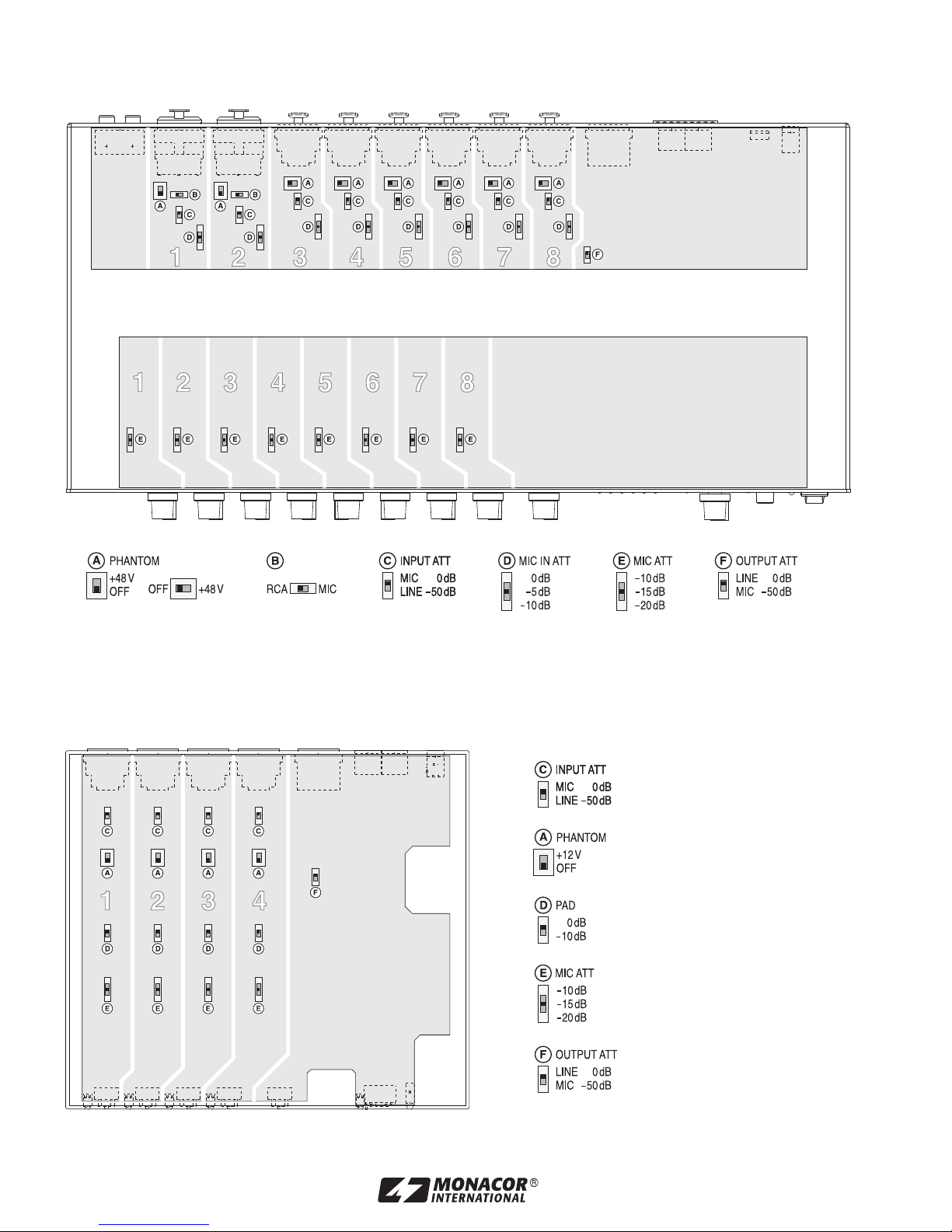
17
CS-4
Schalter im Gerät • Switches in the Unit • Interrupteurs dans lʼappareil • Interruptores del Aparato
CS-8
Page 18

MONACOR INTERNATIONAL GmbH & Co. KG, Zum Falsch 36, 28307 Bremen, Germany
Copyright
©
by MONACOR INTERNATIONAL. All rights reserved. A-1345.99.01.06.2012
www.jts-germany.de
 Loading...