

Page 1
®
Vertrieb von JTS-Produkten – Distribution of JTS products
Bedienungsanleitung
Instruction Manual
Mode d’emploi
Manual de instrucciones
CS-1CU CS-1CH CS-1DU
Konferenzsystem
Conference System
Système de conférence
Sistema de Conferencias
Page 2

2
Bevor Sie einschalten …
Wir wünschen Ihnen viel Spaß mit Ihrem neuen
Gerät von JTS. Bitte lesen Sie diese Bedienungsanleitung vor dem Betrieb gründlich
durch. Nur so lernen Sie alle Funktionsmöglichkeiten kennen, vermeiden Fehlbedienungen
und schützen sich und Ihr Gerät vor eventuellen
Schäden durch unsachgemäßen Ge brauch.
Heben Sie die Anleitung für ein späteres Nach lesen auf.
Der deutsche Text beginnt auf der Seite 4.
Before switching on …
We wish you much pleasure with your new JTS
unit. Please read these operating instructions
carefully prior to operating the unit. Thus, you
will get to know all functions of the unit, op er ating errors will be prevented, and yourself and
the unit will be protected against any damage
caused by improper use. Please keep the operating instructions for later use.
The English text starts on page 10.
Avant toute installation …
Nous vous souhaitons beaucoup de plaisir à utiliser cet appareil JTS. Lisez ce mode dʼemploi
entièrement avant toute utilisation. Uniquement
ainsi, vous pourrez apprendre lʼen semble des
possibilités de fonctionnement de lʼappareil, éviter toute manipulation erronée et vous protéger,
ainsi que lʼappareil, de dommages éventuels
engendrés par une utilisation inadaptée.
Conservez la notice pour pouvoir vous y reporter ultérieurement.
La version française se trouve page 16.
Antes de cualquier instalación ...
Le deseamos una buena utilización para su
nue vo aparato de JTS. Por favor, lea estas in s trucciones de uso atentamente antes de hacer
funcionar el aparato. De esta manera conocerá
todas las funciones de la unidad, se pre vendrán
errores de operación, usted y el apa rato estarán
protegidos en contra de todo daño causado
por un uso inadecuado. Por favor, guarde las
instrucciones para una futura utilización.
La versión española comienza en la página 22.
DEUTSCHENGLISHFRANÇAISESPAÑOL
Page 3
3
123 4 5 6789
10 11 12 13 14 15 16 17 18 19 20
28
24
30
31
32
33
21
22
25
24
23
26
27
29
Page 4

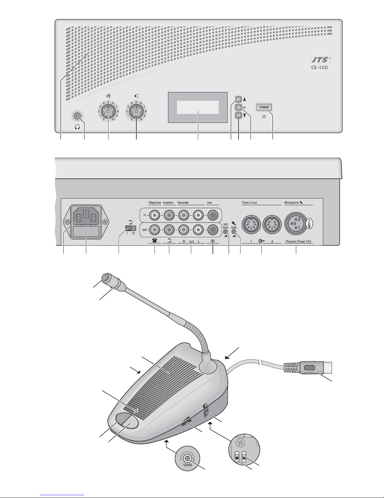
Auf der ausklappbaren Seite 3 finden Sie alle be schriebenen Bedienelemente und Anschlüsse.
1 Übersicht der Bedienelemente
und Anschlüsse
1.1 Steuergerät CS-1CU (Oberseite)
1 Lautsprecher
2 Kopfhörerausgang als 3,5-mm-Klinkenbuchse;
beim Anschluss eines Steckers an die Buchse wird
der Lautsprecher (1) ausgeschaltet
3 Lautstärkeregler für die Kopfhörerbuchse (2)
und den Lautsprecher (1)
4 Regler (Drehschalter mit 11 Positionen) für die
Lautstärke aller Lautsprecher und die maximale
Lautstärke aller Kopfhörer am Steuergerät und an
allen Sprechstellen
5 Display
6 Taste zum Starten und Stoppen der Stoppuhr
im Einstellmenü:
zum Wählen der Betriebsart und
zum Ändern einer Einstellung
7 Taste zum Rücksetzen der Stoppuhr (bei ange-
haltener Zählung)
im Einstellmenü:
zum Wählen der Betriebsart und
zum Ändern einer Einstellung
8 Taste SET bei kurzem Drücken zum Umschalten
zwischen der Anzeige von Datum/ Uhrzeit und dem
Stoppuhrbetrieb; bei längerem Drücken (ca. 2 s)
zum Aufruf des Einstellmenüs
im Einstellmenü:
zur Bestätigung eines gewählten
Menüpunktes oder einer Einstellung
9 Netzschalter POWER
1.2 Steuergerät CS-1CU (Rückseite)
10 Netzbuchse zum Anschluss an eine Netzsteckdose
(230 V~/ 50 Hz) über das beiliegende Kabel
11 Halterung für die Netzsicherung;
eine durchgebrannte Sicherung nur durch eine
gleichen Typs ersetzen
12 Umschalter zum Umleiten der Tonsignale über
ein an den Buchsen „Insertion“ (14) angeschlossenes Gerät zur Signalbearbeitung (z. B. Equalizer)
Position „I“: das Gerät ist in den Signalweg ein-
geschleift
Position „O“: das Gerät ist nicht in den Signalweg
eingeschleift
13 Cinch-Buchsen „Telephone“ mit Eingang (in) und
Ausgang (out) zum Anschluss einer Telefonanlage
über einen Telefonkoppler
14 Cinch-Buchsen „Insertion“ mit Eingang (in) und
Ausgang (out) zum Einschleifen eines Gerätes zur
externen Signalbearbeitung (z. B. Equalizer) in den
Signalweg
15 Cinch-Buchsen „Recorder“ mit Eingang (in) und
Ausgang (out) zum Anschluss eines Aufnahme gerätes; die Buchsen sind jeweils für den linken (L)
und rechten (R) Kanal eines Stereorekorders vorhanden, die Signalverarbeitung im Konferenzsystem erfolgt jedoch monophon.
16 Cinch-Buchsen „Line“ mit dem Eingang (in) zum
Anschluss einer Signalquelle mit Line-Ausgangspegel und dem Ausgang (out) zum Anschluss an
eine Verstärkeranlage
17 Regler „ Gain“ zur Einstellung der Eingangs-
verstärkung für die Eingänge „Recorder in“ (15)
18 Regler „ Gain“ zur Einstellung der Eingangsver-
stärkung für den Mikrofoneingang (20)
19 Buchsen „Trunk in/out“ 1 und 2 zum Anschluss der
Sprechstellen; an jede der beiden Buchsen kann
eine Kette von max. 25 Sprechstellen CS-1CH
und/oder CS-1DU angeschlossen werden
20 Mikrofoneingang als XLR-Buchse; der Eingang lie-
fert eine Phantomspeisung von 12 V, deshalb nur
Mikrofone mit symmetrisch beschaltetem Ausgang
anschließen!
1.3 Sprechstelle CS-1CH (CS-1DU)
Die Abbildung 3 zeigt die Sprechstelle CS-1CH (für
den Konferenzleiter), Abweichungen gegenüber der
Sprechstelle CS1-DU (für die Konferenzteilnehmer)
sind bei den jeweiligen Bedienelementen beschrieben.
21 Mikrofon
22 Ring leuchtet, wenn das Mikrofon eingeschaltet ist
oder beim Systemtest (
Kap. 5.7)
23 LED leuchtet, wenn das Mikrofon eingeschaltet ist
oder beim Systemtest (
Kap. 5.7)
24 zwei 3,5-mm-Klinkenbuchsen zum Anschluss von
Kopfhörern; beim Anschluss eines Steckers an
eine der Buchsen wird der Lautsprecher (25) ausgeschaltet
25 Lautsprecher
26
Nur bei CS-1CH:
Vorrang-Taste zum Unterbrechen
einer Diskussion zwischen Konferenzteilnehmern
durch den Konferenzleiter
27 Sprechtaste zum Ein- und Ausschalten des Mikro-
fons
28 Buchse zum Anschluss der nächsten Sprechstelle
29 Stecker zum Anschluss an eine der Buchsen
„Trunk in/out“ (19) am Steuergerät oder an die
Buchse (28) einer anderen Sprechstelle
30 Lautstärkeregler für die Kopfhörerausgänge (24)
31 Regler GAIN zur Einstellung der Mikrofonverstär-
kung
32
Nur bei CS-1CH:
Schalter für den automatischen
Signalton am Beginn einer Durchsageunterbrechung: in der oberen Schalterposition ist der Signalton zu hören
4
DEUTSCH
Page 5

5
33
Nur bei CS-1CH:
Schalter zur Bestimmung des
Verhaltens nach einer Durchsageunterbrechung
untere Position: Mikrofone der Sprechstellen, die
vor der Unterbrechung eingeschaltet waren, werden nach der Unterbrechung automatisch wieder
eingeschaltet
obere Position: nach einer Unterbrechung bleiben
die Mikrofone aller Teilnehmersprechstellen ausgeschaltet
2 Hinweise für den sicheren Gebrauch
Die Geräte (das Steuergerät CS1-CU und die Sprechstellen CS-1DU/-1CH) entsprechen allen erforderlichen Richtlinien der EU und sind deshalb mit
gekennzeichnet.
Beachten Sie auch unbedingt die folgenden Punkte:
G
Verwenden Sie die Geräte nur im In nen bereich und
schützen Sie sie vor Tropf- und Spritzwasser, hoher
Luftfeuchtigkeit und Hitze (zu lässiger Einsatztemperaturbereich 0 – 40°C).
G
Stellen Sie keine mit Flüssigkeit gefüllten Gefäße,
z. B. Trinkgläser, auf die Geräte.
G
Die im Steuergerät entstehende Wärme muss durch
Luftzirkulation abgegeben werden. Decken Sie die
Lüftungsöffnungen nicht ab.
G
Nehmen Sie das Steuergerät nicht in Betrieb oder
zie hen Sie sofort den Netzstecker aus der Steckdose,
1. wenn sichtbare Schäden an einem der Geräte
oder an der Netzanschlussleitung vorhanden
sind,
2. wenn nach einem Sturz oder Ähnlichem der Verdacht auf einen Defekt besteht,
3. wenn Funktionsstörungen auftreten.
Geben Sie die Geräte in jedem Fall zur Reparatur in
eine Fachwerkstatt.
G
Ziehen Sie den Netzstecker nie am Kabel aus der
Steckdose, fassen Sie immer am Stecker an.
G
Verwenden Sie für die Reinigung nur ein trockenes,
weiches Tuch, niemals Wasser oder Chemikalien.
G
Werden die Geräte zweckentfremdet, nicht richtig
angeschlossen, falsch be dient oder nicht fach gerecht repariert, kann keine Haftung für daraus resultierende Sach- oder Personenschäden und keine
Garantie für die Geräte übernommen werden.
3 Einsatzmöglichkeiten
Das CS-1-System dient der technischen Unterstützung von Konferenzen und Diskussionsveranstaltungen mit bis zu 50 Sprechstellen. Über zusätzliche
Audio-Anschlüsse am Steuergerät CS-1CU lassen
sich weitere Geräte (wie z. B. Aufnahmegeräte, Verstärker, Funkmikrofonanlagen, Equalizer, Telekommunikation) problemlos integrieren.
Jede Sprechstelle (CS-1DU und CS-1CH) verfügt
über eine hochwertige Mikrofonkapsel, einen Lautsprecher und zwei Kopfhöreranschlüsse mit einem
Lautstärkeregler. Die Sprechstellen für die Konferenzleitung CS-1CH sind zusätzlich mit einer Vorrangtaste
ausgestattet, die es einem Konferenzleiter ermöglicht,
die Gespräche anderer Teilnehmer für eigene Mitteilungen zu unterbrechen.
Verschiedene Diskussionsmodi (z.B. eine wählbare Anzahl gleichzeitiger Sprecher oder eine auto matisch begrenzte Sprechzeit), eine Datum- und
Uhrzeitanzeige, eine unabhängige Stoppuhr, eine Tastensperre der Steuereinheit sowie eine Testfunktion für
alle angeschlossenen Sprechstellen emöglichen einen
vielseitigen Einsatz des Systems.
4 Anschlüsse herstellen
Die Herstellung oder Änderung von Anschlüssen nur
bei ausgeschalteten Geräten durchführen!
4.1 Sprechstellen
Für den Anschluss der Sprechstellen stehen am Steuergerät die beiden Buchsen „Trunk in/out“ (19) zur Verfügung. An jede der beiden Buchsen kann eine Kette
von max. 25 Sprechstellen vom Typ CS-1CH und/oder
CS-1DU angeschlossen werden.
1) Den Stecker (29) der ersten Sprechstelle an eine
der Buchsen „Trunk in/out“ (19) anschließen.
2) Den Stecker (29) der zweiten Sprechstelle an die
Buchse (28) auf der Rückseite ersten Sprechstelle
anschließen (oder an die andere Buchse „Trunk
in/out“ am Steuergerät).
3) Auf die gleiche Weise weitere Sprechstellen verbin-
den. Die Reihenfolge von CS-1CH- und CS-1DU-
Geräten kann beliebig sein. Ebenso kann die
Anzahl der an den beiden Buchsen am Steuergerät
angeschlossenen Sprechstellen unterschiedlich
sein.
WARNUNG Das Steuergerät wird mit lebens ge -
fährlich hoher Netzspannung versorgt.
Nehmen Sie deshalb niemals selbst
Eingriffe am Gerät vor. Durch unsachgemäßes Vorgehen besteht die Gefahr
eines elektrischen Schlages.
Sollen die Geräte endgültig aus dem Betrieb
genommen werden, übergeben Sie sie zur
umweltgerechten Entsorgung einem örtlichen Recyclingbetrieb.
DEUTSCH
Page 6

4.2 Zusätzliches Mikrofon
Ein zusätzliches Mikrofon oder der Empfänger eines
Funkmikrofons kann über die Buchse „Microphone“
(20) angeschlossen werden. Für Mikrofone, die eine
Phantomspeisung benötigen, liegt an der Buchse eine
Spannung von 12 V an. Aus diesem Grund dürfen
hier keine Mikrofone oder Funkempfänger mit asymmetrischem Ausgangssignal angeschlossen werden,
da diese Schaden nehmen könnten.
4.3 Aufnahmegerät
Für den Mitschnitt einer Diskussion den Eingang eines
Aufnahmegerätes an die Cinch-Buchsen „Recorder
out“ (15) anschließen. Der Signalpegel an den Buchsen ist unabhängig von der eingestellten Lautsprecherlautstärke.
Für die Wiedergabe einer Aufnahme den Ausgang
des Aufnahmegerätes an die Cinch-Buchsen „Recorder in“ anschließen. Die Buchsen sind jeweils für den
linken (L) und rechten (R) Kanal eines Stereorekorders
vorhanden, die Signalverarbeitung im Konferenzsystem erfolgt jedoch monophon.
4.4 Signalquelle mit Line-Pegel
Eine Mono-Signalquelle mit Line-Pegel (z. B. der Ausgang eines Mischpultes) kann an die Cinch-Buchse
„Line in“ (16) angeschlossen werden.
Steht nur eine Stereo-Signalquelle zur Verfügung
und wird der Eingang „Recorder in“ nicht benötigt,
kann diese auch dort angeschlossen werden.
4.5 Verstärkeranlage
Soll die Diskussion über eine Verstärkeranlage wiedergegeben werden, den Eingang des Verstärkers
oder Mischpultes mit der Buchse „Line out“ (16) verbinden.
4.6 Telefonkoppler
Um einen Gesprächspartner per Telefon in eine Diskussion zu integrieren, kann an die Buchsen „Telephone“ (13) eine Telefon-Koppeleinrichtung angeschlossen werden. Dieser Telefonkoppler sorgt für die
nötige elektrische Anpassung zwischen dem Telefonnetz und dem Konferenzsystem.
Vorsicht: Versuchen Sie nie, eine Telefonleitung direkt
an das Konferenzsystem anzuschließen.
4.7 Externe Signalbearbeitung einschleifen
Zum Einschleifen eines zusätzliche Gerätes zur Signalbearbeitung (z. B. eines Equalizers zur Klang anpassung oder eines Kompressors zur Dynamikbegrenzung) in den Signalweg des Konferenzsystems,
den Eingang des Gerätes mit der Buchse „Insertion
out“ (14) und seinen Ausgang mit der Buchse „Insertion in“ verbinden.
Damit die externe Klangbearbeitung wirksam ist,
den Schalter (12) in die Position „I“ schieben.
4.8 Kopfhörer
Alternativ zum Hören über die Lautsprecher lassen
sich Kopfhörer verwenden. Dazu ist am Steuergerät
eine Buchse (2) vorhanden, die Sprechstellen sind
jeweils mit einer Buchse (24) auf der rechten und linken Seite ausgestattet. Sobald ein Stecker an einer
Buchse angeschlossen ist, wird der betreffende Lautsprecher abgeschaltet.
4.9 Stromversorgung
Zum Schluss das beiliegende Netzkabel zuerst in die
Netzbuchse (10) und dann in eine Netzsteckdose
(230 V~/50 Hz) stecken.
5 Bedienung
Hinweis: Ist an den Buchsen „Insertion“ (14) kein
Gerät zur externen Klangbearbeitung angeschlossen
oder soll ein dort angeschlossenes Gerät nicht genutzt
werden, den Schalter (12) in die Position „O“ schieben.
Den Lautstärkeregler (4) zunächst auf „1“ drehen
und das Steuergerät mit dem Schalter POWER (9)
einschalten. Das Display (5) zeigt die zuletzt gewählte
Betriebsart und das Datum (Format: Jahr -Monat - Tag)
sowie die Uhrzeit (Format: Stunde : Minute : Sekunde).
Zur Änderung der Uhreinstellung
Kap. 5.5.
5.1 Betriebsart wählen
1) Die Taste SET (8) ca. 2 s lang drücken. Anstelle des
Datums blinkt jetzt , solange das Einstellmenü
aufgerufen ist.
2) Mit der Taste (6) oder (7) eine der folgenden
Betriebsarten wählen:
„Over Ride Mode“
Ein Konferenzteilehmer kann mit kurzem Drücken
der Sprechtaste (27) sein Mikrofon einschalten. Die
LED (23) an seiner Sprechstelle und der Ring (22)
seines Mikrofons leuchten, solange das Mikrofon
eingeschaltet ist. Zum Wiederausschalten die Taste
erneut drücken.
Sobald ein anderer Konferenzteilnehmer sein
Mikrofon einschaltet, wird das Mikrofon seines Vorredners automatisch abgeschaltet.
Das Mikrofon eines Konferenzleiters an einer
Sprechstelle CS-1CH ist von dieser Abschaltung
nicht betroffen. Es kann gleichzeitig zu den anderen
Sprechstellen ein- und ausgeschaltet werden.
„Chairman Only“
Ausschließlich ein Konferenzleiter an einer Sprechstelle CS-1CH kann sein Mikrofon über die Sprechtaste (27) ein- und ausschalten, die Mikrofone der
Teilnehmersprechstellen bleiben ausgeschaltet.
„Open Mode“
Eine einstellbare Anzahl von Teilnehmern kann
gleichzeitig sprechen. Ist die maximal zulässige
Anzahl von Mikrofonen eingeschaltet, lässt sich
6
DEUTSCH
Page 7

kein anderes Mikrofon dazuschalten. Ein Teilnehmer mit einer weiteren Wortmeldung muss warten,
bis einer seiner Vorredner sein Mikrofon wieder
ausgeschaltet hat.
Ein Konferenzleiter an einer Sprechstelle CS1CH ist von dieser Beschränkung ausgenommen.
Er kann sein Mikrofon jederzeit über die Sprechtaste (27) ein- und ausschalten.
„Timer Mode“
Diese Betriebsart funktioniert wie „Open Mode“,
jedoch wird ein Mikrofon, nachdem es 30 s eingeschaltet war, automatisch abgeschaltet. Dadurch
wird verhindert, dass ein Teilnehmer auf Dauer die
Diskussion anderer Teilnehmer blockiert, wenn er
z. B. vergessen hat, sein Mikrofon auszuschalten.
3)
Nur bei den Betriebsarten „Open Mode“ und „Timer
Mode“:
Die Taste SET drücken: das Symbol blinkt.
Mit der Taste oder die gewünschte maximale
Anzahl gleichzeitiger Sprecher (1 – 4) einstellen.
4) Mit der Taste SET die Auswahl bestätigen.
Im Display erscheint kurz „Saving“ und das Einstellmenü wird verlassen.
5.2 Bedienung der Sprechstellen CS-1DU
1) Zum Einschalten des Mikrofons die Sprechtaste
(27) kurz drücken. Die LED (23) und der Ring (22)
leuchten, sobald das Mikrofon eingeschaltet ist.
Hinweis:
Das Einschalten kann aber auch durch das
Steuergerät (
Kap. 5.1) oder über die Vorrangtaste
einer Konferenzleitersprechstelle (
Kap. 5.3.1)
verhindert sein.
2) Beim Anschluss eines Kopfhörers an eine der
Buchsen (24) wird der Lautsprecher (25) der
Sprechstelle abgeschaltet. Die Kopfhörerlautstärke
kann, abhängig von der am Steuergerät eingestellten Maximallautstärke, mit dem Regler (30) an der
rechten Seite der Sprechstelle für beide Buchsen
gemeinsam eingestellt werden.
3) Zum Ausschalten des Mikrofons die Sprechtaste
(27) erneut drücken. Die LED (23) und der Leuchtring (22) erlöschen.
Hinweis:
Das Ausschalten kann auch durch das
Steuergerät (
Kap. 5.1) oder über die Vorrangtaste
einer Konferenzleitersprechstelle (
Kap. 5.3.1)
vorzeitig erfolgen.
5.2.1 Mikrofonempfindlichkeit einstellen
Mit dem Regler GAIN (31) auf der Unterseite jeder
Sprechstelle kann mithilfe eines kleinen Schraubendrehers die Verstärkung eingestellt und damit die
Empfindlichkeit des Mikrofons an einen Sprecher an gepasst werden.
5.3 Konferenzleitersprechstellen CS-1CH
Das Ein- und Ausschalten des Mikrofons über die
Sprechtaste sowie die Einstellung der Kopfhörerlautstärke und der Mikrofonempfindlichkeit der Konferenzleitersprechstellen CS-1CH erfolgt wie bei den
Sprechstellen für die übrigen Konferenzteilnehmer
(Kap. 5.2). Das Mikrofon kann aber jederzeit durch
den Konferenzleiter eingeschaltet und nur durch ihn
wieder ausgeschaltet werden.
5.3.1 Vorrangtaste
Die Vorrangtaste bietet dem Konferenzleiter die Möglichkeit, eine Diskussion zwischen Konferenzteilnehmern zu unterbrechen. Solange die Vorrangtaste (26)
gedrückt wird, bleiben die Mikrofone aller Teilnehmersprechstellen ausgeschaltet. Durch die Einstellung der
beiden Schalter auf der Unterseite der Konferenzleitersprechstelle kann das Verhalten beim Drücken und
Loslassen der Vorrangtaste bestimmt werden:
linker Schalter (32)
obere Position: beim Drücken der Vorrangtaste
ertönt ein Signal
untere Position: beim Drücken der Vorrangtaste
ertönt kein Signal
rechter Schalter (33)
obere Position: nach dem Loslassen der Vorrang-
taste bleiben die Mikrofone aller
Teilnehmersprechstellen aus geschaltet
untere Position: alle Mikrofone der Teilnehmer-
sprechstellen, die vor dem Drücken der Vorrangtaste eingeschaltet waren, werden nach dem
Loslassen der Taste automatisch
wieder eingeschaltet
5.4 Lautstärkeeinstellungen am Steuergerät
5.4.1 Gesamtlautstärke
Mit dem Regler (4) die Lautstärke aller Lautsprecher
und die maximale Lautstärke aller Kopfhöreranschlüsse
am Steuergerät und an allen angeschlossenen Sprechstellen einstellen. Tritt ein Rückkopplungspfeifen auf,
weil z. B. die Sprechstellen zu eng bei einander stehen
und die Mikrofonempfindlichkeit an den Sprechstellen
sehr hoch eingestellt ist (
Kap. 5.2.1), den Regler
entsprechend niedriger einstellen. Der Regler hat 11
Schaltpositionen, in Position „0“ sind alle Lautsprecher
und Kopfhörer ausgeschaltet. Der Signalpegel am Ausgang „Recorder out“ (15) wird durch den Regler nicht
beeinflusst.
VORSICHT Stellen Sie die Kopfhörerlautstärke
nie sehr hoch ein. Hohe Lautstärken
können auf Dauer das Gehör schädigen! Das Ohr gewöhnt sich an sie
und empfindet sie nach einiger Zeit
als nicht mehr so hoch. Darum eine
hohe Lautstärke nach der Gewöhnung nicht weiter erhöhen.
7
DEUTSCH
Page 8

5.4.2 Lautsprecher und Kopfhörer am Steuergerät
Mit dem Regler (3) die Lautstärke für die Kopfhörerbuchse (2) und den Lautsprecher (1) einstellen. Beim
Anschluss eines Kopfhörers an die Buchse wird der
Lautsprecher abgeschaltet.
5.4.3 Lautstärke für externes Mikrofon
Bei Bedarf kann die Lautstärke für ein an der Buchse
„Microphone“ (20) angeschlossenes Mikrofon oder
einen Empfänger eines Funkmikrofons angepasst
werden. Den Regler „ Gain“ (18) mithilfe eines kleinen Schraubendrehers nur so weit aufdrehen, dass
der Ton nicht verzerrt wiedergegeben wird.
5.4.4 Lautstärke für den Eingang „Recorder in“
Bei Bedarf kann die Lautstärke für eine an den Buchsen „Recorder in“ (15) angeschlossene Signalquelleangepasst werden. Den Regler „ Gain“ (17) mithilfe eines kleinen Schraubendrehers nur so weit
aufdrehen, dass der Ton nicht verzerrt wiedergegeben
wird.
5.5 Datum und Uhrzeit einstellen
Das Steuergerät verfügt über eine eigene Uhr und
zeigt in der unteren Zeile des Displays (5) in folgendem Format das Datum und die Uhrzeit an:
Jahr - Monat- Tag Stunde : Minute: Sekunde
Für die Einstellung der Uhr:
1) Die Taste SET (8) ca. 2 s lang drücken. Anstelle des
Datums blinkt jetzt , solange das Einstellmenü
aufgerufen ist.
2) Die Taste (6) oder (7) so oft drücken, bis „Set
Date/ Time“ angezeigt wird.
3) Die Taste SET kurz drücken. Die Jahreszahl wird
hervorgehoben.
4) Mit der Taste (6) oder (7) das Jahr einstellen
und mit der Taste SET bestätigen. Die Monatszahl
wird nun hervorgehoben.
5) Auf die gleiche Weise den Monat, den Tag, die
Stunde, die Minute einstellen. Bei der Einstellung
der Minute wird der Sekundenwert auf Null gesetzt.
6) Mit dem Drücken der Taste SET wird die Einstellung
übernommen. Im Display erscheint kurz „Saving“
und das Einstellmenü wird verlassen.
5.6 Stoppuhr
Zusätzlich zu der Uhr bietet das Steuergerät eine
Stoppuhr-Funktion.
1) Zum Wechsel von der Uhranzeige zur StoppuhrFunktion die Taste SET (8) kurz drücken. Im Display
(5) erscheint jetzt in der unteren Zeile
„Counter 0:00:00“.
2) Die Stoppuhr mit der Taste (6) starten. Die
Anzeige wechselt jetzt zu „Counting“ und die Zeitanzeige beginnt zu laufen.
3) Nach der zu messenden Zeit die Taste erneut
drücken. Die Anzeige wechselt jetzt zu „Stopped“
und die Zeitanzeige bleibt stehen.
4) Zum Zurücksetzen bei angehaltener Stoppuhr die
Taste (7) drücken.
5) Durch kurzes Drücken der Taste SET kann jederzeit, auch bei laufender Stoppuhr, auf die Anzeige
der Uhrzeit und wieder zur Stoppuhr gewechselt
werden.
5.7 Testfunktion
Zum Testen, ob alle Sprechstellen angeschlossen sind:
1) Die Taste SET (8) ca. 2 s lang drücken. Anstelle des
Datums blinkt jetzt , solange das Einstellmenü
aufgerufen ist.
2) Die Taste (6) oder (7) so oft drücken, bis „System Test“ angezeigt wird. Die LEDs (23) und Ringe
(22) aller angeschlossenen Sprechstellen leuchten
auf, die Mikrofone bleiben jedoch ausgeschaltet.
3) Zum Verlassen des Einstellmenüs die Taste oder
so oft drücken, bis „Exit“ angezeigt wird, dann die
Taste SET drücken.
5.8 Tastensperre
Gegen unbeabsichtigtes Bedienen können Tasten
gesperrt werden. Bei aktiver Tastensperre erscheint im
Display (5) oben rechts und die Stoppuhr-Funktion
kann nicht genutzt werden. Für eine normale Bedienung muss die Tastensperre zuerst wieder deaktiviert
werden.
Zum Ein- oder Ausschalten der Tastensperre:
1) Die Taste SET (8) ca. 2 s lang drücken. Im Display
blinkt jetzt .
2) Wenn „Key Lock“ nicht gleich im Display erscheint,
die Taste (6) oder (7) so oft drücken, bis „Key
Lock“ angezeigt wird und mit der Taste SET bestätigen.
3) Mit der Taste „Yes“ wählen, um die Tastensperre
einzuschalten oder mit der Taste „No“ wählen, um
die Tastensperre auszuschalten und mit der Taste
SET bestätigen.
VORSICHT Stellen Sie die Kopfhörerlautstärke nie
sehr hoch ein. Hohe Lautstärken können auf Dauer das Gehör schädigen!
Das Ohr gewöhnt sich an sie und empfindet sie nach einiger Zeit als nicht
mehr so hoch. Darum eine hohe Lautstärke nach der Gewöhnung nicht weiter erhöhen.
8
DEUTSCH
Page 9

6 Technische Daten
6.1 Steuergerät CS-1CU
Anzahl der Sprechstellen: . max. 50 (max. 25 pro
Anschluss)
Max. Gesamtkabellänge: . . 100 m
Eingänge „Line in“, „Telephone in“, „Insertion in“
Anschluss: . . . . . . . . . . . Cinch
Empfindlichkeit: . . . . . . . 200 mV
Max. Pegel: . . . . . . . . . . 3,5 V
Impedanz: . . . . . . . . . . . . 33 kΩ
Eingang „Recorder in“
Anschluss: . . . . . . . . . . . Cinch
Empfindlichkeit: . . . . . . . 100 mV
Max. Pegel: . . . . . . . . . . 1,8 V
Impedanz: . . . . . . . . . . . . 47 kΩ
Eingang „Microphone“
Anschluss: . . . . . . . . . . . XLR
Empfindlichkeit: . . . . . . . 1,6 mV
Max. Pegel: . . . . . . . . . . 2 V
Impedanz: . . . . . . . . . . . . 1,3 kΩ
Phantomspeisung: . . . . . 12V ±1 V über 2 × 680Ω
Ausgänge „Line out“, „Telephone out“, „Insertion out“
Anschluss: . . . . . . . . . . . Cinch
Nennausgangspegel: . . . 200 mV
Max. Ausgangspegel: . . 3,5 V
Impedanz: . . . . . . . . . . . . 500 Ω
Ausgang „Recorder out“
Anschluss: . . . . . . . . . . . Cinch
Nennausgangspegel: . . . 32 mV
Max. Ausgangspegel: . . 1 V
Impedanz: . . . . . . . . . . . . 500 Ω
Sprechstellenanschlüsse „Trunk in/out“
Anschluss: . . . . . . . . . . . 7-pol.-DIN-Buchsen
Stromversorgung: . . . . . . . . 100 – 264 V~/50 – 60 Hz
Leistungsaufnahme: . . . . . . max. 90 VA
Einsatztemperatur: . . . . . . . 0 –40 °C
Abmessungen: . . . . . . . . . . 360 × 150 × 90 mm
Gewicht: . . . . . . . . . . . . . . . 1745 g
6.2 Sprechstellen CS-1CH und CS-1DU
Mikrofontyp: . . . . . . . . . . . . Back-Elektret
Richtcharakteristik: . . . . . . . Niere
Frequenzbereich: . . . . . . . . 50 – 18 000 Hz
Max. Schalldruck: . . . . . . . . 125 dB bei 1 % Klirr -
faktor
Kabellänge: . . . . . . . . . . . . 2,1 m
Abmessungen
(ohne Mikrofon): . . . . . . . . . 170 × 115 × 65 mm
Schwanenhalslänge: . . . . . 400 mm
Gewicht: . . . . . . . . . . . . . . . 1100 g
Änderungen vorbehalten.
1 = Masse / Phantomspeisung
-
2 = Signal + / Phantomspeisung +
3 = Signal
-
/ Phantomspeisung +
1 = Audiosignal (Mikrofone)
2 = Masse
3 = Audiosignal (Lautsprecher)
4 = Steuerleitung 1
5 = Steuerleitung 2
6 = Versorgung +15V
7 = Versorgung
-
15 V
9
DEUTSCH
Diese Bedienungsanleitung ist urheberrechtlich für MONACOR®INTERNATIONAL GmbH & Co. KG ge schützt.
Eine Reproduktion für eigene kommerzielle Zwecke – auch auszugsweise – ist untersagt.
Page 10

All operating elements and connections described
can be found on the fold-out page 3.
1 Operating Elements and Connections
1.1 Controller CS-1CU (upper side)
1 Speaker
2 Headphone output as a 3.5 mm jack; if a plug is
connected to this jack, the speaker (1) will be
switched off
3 Volume control for the headphone jack (2) and
the speaker (1)
4 Control (rotary switch with 11 positions) for the
volume of all speakers and the maximum volume of
all headphones on the controller and on all microphone stations
5 Display
6 Button to start and stop the stopwatch feature
in the setting menu:
to select the operating mode
and to change a setting
7 Button to reset the stopwatch feature (when
counting is stopped)
in the setting menu:
to select the operating mode
and to change a setting
8 Button SET
short actuation: to switch over between the indication of date/time and the stopwatch mode;
longer actuation (approx. 2 seconds) to activate the
setting menu
in the setting menu:
to confirm a menu item selected
or a setting
9 POWER switch
1.2 Controller CS-1CU (rear side)
10 Mains switch for connection to a mains socket
(230 V~/ 50Hz) via the cable provided
11 Support for the mains fuse;
replace a fuse that has blown by one of the same
type only
12 Selector switch to route the audio signals via a
unit for signal processing connected (e. g. equalizer) to the jacks “Insertion” (14)
position “I”: unit inserted into the signal path
position “O”: unit not inserted into the signal path
13 RCA jacks “Telephone” with input (in) and output
(out) to connect a telephone system via a telephone coupler
14 RCA jacks “Insertion” with input (in) and output
(out) to insert a unit for external signal processing
(e. g. equalizer) into the signal path
15 RCA jacks “Recorder” with input (in) and output
(out) to connect a recorder; the jacks are available
for the left (L) channel and right (R) channel
respectively of a stereo recorder; however, signal
processing in the conference system will be monophonic
16 RCA jacks “Line” with input (in) to connect a signal
source with line output level and output (out) to
connect an amplifier system
17 Control “ Gain” to adjust the input amplification
for the inputs “Recorder in” (15)
18 Control “ Gain” to adjust the input amplification for
the microphone input (20)
19 Jacks “Trunk in/out” 1 and 2 to connect the micro-
phone stations; each of the two jacks will allow connection of a chain of up to 25 microphone stations
CS-1CH and/or CS-1DU
20 Microphone input as an XLR jack; the input will
supply a phantom power of 12 V; therefore, connect microphones with balanced output only!
1.3 Microphone station CS-1CH (CS-1DU)
Figure 3 shows the microphone station CS-1CH (for
the chairperson); deviations from the microphone station CS-1DU (for delegates) are described in the corresponding operating elements.
21 Microphone
22 Ring; will light up when the microphone is switched
on or when a system test is performed (
chapter
5.7)
23 LED; will light up when the microphone is switched
on or when a system test is performed (
chapter
5.7)
24 Two 3.5 mm jacks to connect headphones; if a plug
is connected to one of these jacks, the speaker (25)
will be switched off
25 Speaker
26
for CS-1CH only:
Priority button for the chairperson
to interrupt a discussion between delegates
27 Talk button to switch on/off the microphone
28 Jack to connect the next microphone station
29 Plug for connection to one of the jacks “Trunk
in/out” (19) on the controller or to the jack (28) of
another microphone station
30 Volume control for the headphone outputs (24)
31 Control GAIN to adjust the microphone amplifica-
tion
32
for CS-1CH only:
Switch for the automatic acoustic
signal which will sound when an announcement is
interrupted; the acoustic signal will be audible
when the switch is in the upper position
33
for CS-1CH only:
Switch to define the behaviour
after interrupting an announcement
lower position: microphones of stations which had
been switched on before the interruption will be automatically switched on again after the interruption
upper position: after an interruption, the microphones of all delegate stations will remain switched
off
10
ENGLISH
Page 11

2 Safety Notes
The units (the controller CS-1CU and the microphone
stations CS-1DU/CS-1CH) correspond to all required
directives of the EU and are therefore marked with .
Please observe the following items in any case:
G
The units are suitable for indoor use only. Protect
them against dripping water and splash water, high
air humidity and heat (admissible ambient temperature range 0 – 40°C).
G
Do not place any vessel filled with liquid on the units,
e. g. a drinking glass.
G
The heat generated inside the controller must be dissipated by air circulation; never cover the air vents.
G
Do not operate the controller and immediately disconnect the mains plug from the socket
1. if one of the units or the mains cable is visibly
damaged,
2. if a defect might have occurred after a unit was
dropped or suffered a similar accident,
3. if malfunctions occur.
In any case the units must be repaired by skilled personnel.
G
Never pull the mains cable for disconnecting the
mains plug from the socket, always seize the plug.
G
For cleaning only use a dry, soft cloth; never use
water or chemicals.
G
No guarantee claims for the units and no liability for
any resulting personal damage or material damage
will be accepted if the units are used for other purposes than originally intended, if they are not correctly connected or operated, or if they are not
repaired in an expert way.
G
Important for U. K. Customers!
The wires in this mains lead are coloured in
accordance with the following code:
green/yellow = earth
blue = neutral
brown = live
As the colours of the wires in the mains lead of this
appliance may not correspond with the coloured
markings identifying the terminals in your plug, proceed as follows:
1. The wire which is coloured green and yellow must
be connected to the terminal in the plug which is
marked with the letter E or by the earth symbol ,
or coloured green or green and yellow.
2. The wire which is coloured blue must be connected to the terminal which is marked with the
letter N or coloured black.
3. The wire which is coloured brown must be connected to the terminal which is marked with the
letter L or coloured red.
Warning – This appliance must be earthed.
3 Applications
The CS-1 system is used for technical support of conferences and discussion meetings with up to 50 microphone stations. Via additional audio connections on
the controller CS-1CU, further units (e. g. recorders,
amplifiers, wireless microphone systems, equalizers,
telecommunication) will easily be integrated.
Each microphone station (CS-1DU and CS-1CH) is
equipped with a high-quality microphone cartridge, a
speaker and two headphone jacks with a volume
control. CS-1CH, the microphone stations for chair persons are also provided with a priority button which
will allow chairpersons to interrupt other delegates for
their own announcements.
Various discussion modes (e. g. a defined number
of delegates talking at the same time or a talking time
with automatic limit), an indication of date and time, a
separate stopwatch feature, a key lock feature for the
controller and a test feature for all microphone stations
connected will allow versatile applications of the system.
4 Making Connections
Always switch off the units prior to making or changing
any connections!
4.1 Microphone stations
For connecting the microphone stations, the two jacks
“Trunk in/out” (19) are provided on the controller. Each
of the two jacks will allow connection of a chain of up
to 25 microphone stations of the type CS-1CH and/or
CS-1DU.
1) Connect the plug (29) of the first microphone station
to one of the jacks “Trunk in/out” (19).
2) Connect the plug (29) of the second microphone
station to the jack (28) on the rear side of the first
microphone station (or to the other jack “Trunk
in/out” on the controller).
3) Connect further microphone stations in the same
way. The CS-1CH and CS-1DU units may be con-
nected in any order. The number of microphone sta-
tions connected to the two jacks on the controller
may also be different.
4.2 Additional microphone
It will be possible to connect an additional microphone
or the receiver of a wireless microphone via the jack
“Microphone”(20). For microphones requiring a phantom
If the units are to be put out of operation
definitively, take them to a local recycling
plant for a disposal which will not be harmful
to the environment.
WARNING The controller uses dangerous mains
voltage. Leave servicing to skilled personnel only. Inexpert handling or modification of the unit may result in electric
shock.
11
ENGLISH
Page 12

power supply, a voltage of 12 V is present at this jack.
Therefore, do not connect any microphones or wireless receivers with unbalanced output signal to this
jack; otherwise they may be damaged.
4.3 Recorder
To record a discussion, connect the input of a recorder
to the RCA jacks “Recorder out” (15). The signal level
at these jacks will be independent of the speaker volume adjusted.
To reproduce a recording, connect the output of the
recorder to the RCA jacks “Recorder in”. The jacks are
available for the left (L) channel and the right (R) channel respectively of a stereo recorder; however, signal
processing in the conference system will be monophonic.
4.4 Signal source with line level
A mono signal source with line level (e. g. the output of
a mixer) can be connected to the RCA jack “Line in”
(16).
If only a stereo signal source is available and the
input “Recorder in” is not used, the source can be connected to this input.
4.5 Amplifier system
To reproduce the discussion via an amplifier system,
connect the input of the amplifier or mixer to the jack
“Line out” (16).
4.6 Telephone coupler
To allow participation in the discussion by phone, a
telephone coupler can be connected to the jacks “Telephone” (13). This telephone coupler will electrically
adapt the telephone network to the conference system
as required.
Caution: Never try to connect a telephone line directly
to the conference system!
4.7 Inserting external signal processing
To insert an additional unit for signal processing (e. g.
an equalizer for matching the sound or a compressor
for dynamic limiting) into the signal path of the conference system, connect the input of the unit to the jack
“Insertion out” (14) and its output to the jack “Insertion
in”.
Set the switch (12) to position “I” so that the
external sound processing will take effect.
4.8 Headphones
As an alternative to the speakers, headphones can be
used for hearing. For this purpose, the controller is provided with a jack (2), the microphone stations are
equipped with a jack (24) on the left and on the right
each. Once a plug is connected to a jack, the corresponding speaker will be switched off.
4.9 Power supply
Finally connect the mains cable provided to the mains
jack (10) first, then connect it to a mains socket
(230 V~/50 Hz).
5 Operation
Note: If no unit for external sound processing is con-
nected to the jacks “Insertion” (14) or if a unit connected to these jacks is not used, set the switch (12)
to position “O”.
Set the volume control (4) to “1” first, then switch on
the controller with the POWER switch (9). The display (5) will show the last operating mode selected and
also the date (format: year - month - day) and the time
(format: hour : minute: second).
To set the clock
chapter 5.5.
5.1 Selecting the operating mode
1) Keep the button SET (8) pressed for approx. 2 seconds. Instead of the date, will keep flashing
while the setting menu is activated.
2) With the buttons (6) or (7), select one of the following operating modes:
“Over Ride Mode”
A delegate will switch on his/ her microphone by
shortly pressing the talk button (27). The LED (23)
at this microphone station and the ring (22) of this
microphone will light up as long as the microphone
is switched on. To switch it off, press the button
once again.
Once another delegate switches on his/ her
microphone, the microphone of the delegate talking
before will be switched off automatically.
Switching-off will not affect the microphone of a
chairperson at a microphone station CS-1CH. It will
be possible to switch it on/off at the same time as
the other microphone stations.
“Chairman Only”
Only a chairperson at a microphone station CS1CH will be able to switch on/off his/ her microphone
via the talk button (27); the microphones of the delegates will remain switched off.
“Open Mode”
A defined number of delegates will be able to talk at
the same time. If the maximum number of microphones is switched on, it will not be possible to add
another microphone. A delegate requesting to
speak will have to wait until one of the delegates
talking before has switched off his/ her microphone.
This limitation will not apply to a chairperson at a
microphone station CS-1CH; he/she will be able to
switch on or off his/ her microphone via the talk button (27) at any time.
“Timer Mode”
This operating mode is similar to the “Open Mode”;
however, the microphone will be automatically
switched off after 30 seconds. Thus, a delegate will
12
ENGLISH
Page 13

not be able to permanently prevent a discussion of
other delegates, e. g. when forgetting to switch off
his/ her microphone.
3)
For the operating modes “Open Mode” and “Timer
Mode” only:
Press the button SET: the symbol will flash.
With the button or , adjust the maximum number of delegates talking at the same time (1 – 4).
4) Confirm the selection with the button SET.
The display will shortly show “Saving” and the setting
menu will disappear.
5.2 Operation of the microphone stations
CS-1DU
1) To switch on the microphone, shortly press the talk
button (27). The LED (23) and the ring (22) will light
up once the microphone is switched on.
Note:
Switching on, however, may be prevented by
the controller (chapter 5.1) or via the priority button of the microphone station for a chairperson
(
chapter 5.3.1).
2) If headphones are connected to one of the jacks
(24), the speaker (25) of the microphone station will
be switched off. Depending on the maximum volume adjusted on the controller, the headphone volume can be adjusted with the control (30) on the
right of the microphone station for both jacks
together.
3) To switch off the microphone, press the talk button
(27) once again. The LED (23) and the light ring
(22) will be extinguished.
Note:
The microphone may also be switched off at
any time by the controller (chapter 5.1) or via the
priority button of the microphone station for a chairperson (chapter 5.3.1).
5.2.1 Adjusting the microphone sensitivity
Via the control GAIN (31) on the lower side of each
microphone station, it will be possible to adjust the
amplification and thus to adapt the sensitivity of the
microphone to the delegate by means of a small
screwdriver.
5.3 Microphone stations for chairpersons
CS-1CH
Switching on and switching off the microphone via the
talk button and the adjustment of the headphone volume and the microphone sensitivity of the microphone
stations for chairpersons CS-1CH is the same as for
the microphone stations for the other delegates
(
chapter 5.2). However, the microphone can be
switched on by the chairperson at any time and only be
switched off by him/her.
5.3.1 Priority button
The priority button allows the chairperson to interrupt a
discussion between delegates. As long as the priority
button (26) is pressed, the microphones of all delegate
stations will remain switched off. The adjustment of the
two switches on the lower side of the microphone station for a chairperson will define the behaviour when
the priority button is pressed or released:
left switch (32)
upper position: when the priority button is pressed,
a signal will sound
lower position: when the priority button is pressed,
no signal will sound
right switch (33)
upper position: when the priority button is re -
leased, the microphones of all
delegate stations will remain
switched off
lower position: all microphones of delegate sta-
tions which had been switched on
before the priority button was
pressed, will be automatically
switched on again when the button is released
5.4 Volume adjustments on the controller
5.4.1 Total volume
With the control (4), adjust the volume of all speakers and the maximum volume of all headphone connections on the controller and at all microphones stations connected. In case of feedback howling, e. g. if
the microphone stations are too close together and the
microphone sensitivity on the microphone stations is
adjusted to a very high level (
chapter 5.2.1), turn
back the control accordingly. The control offers 11
positions, in position “0”, all speakers and headphones
will be switched off. The signal level at the output
“Recorder out” (15) will not be affected by this control.
5.4.2 Speaker and headphones on the controller
With the control (3), adjust the volume for the headphone jack (2) and the speaker (1). If headphones are
connected to the jack, the speaker will be switched off.
CAUTION: Never adjust the headphones to a very
high volume. Permanent high volumes
may damage your hearing! The human
ear will get accustomed to high volumes
which do not seem to be that high after
some time. Therefore, do not further
increase a high volume after getting
used to it.
CAUTION: Never adjust the headphones to a
very high volume. Permanent high
volumes may damage your hearing!
The human ear will get accustomed
to high volumes which do not seem
to be that high after some time.
Therefore, do not further increase a
high volume after getting used to it.
13
ENGLISH
Page 14

5.4.3 Volume for external microphone
If required, match the volume for a microphone connected to the jack “Microphone” (20) or for a receiver
of a wireless microphone: By means of a small screwdriver, turn up the control “ Gain” (18) only to such an
extent that the sound reproduced will not distort.
5.4.4 Volume for the input “Recorder in”
If required, match the volume for a signal source connected to the jacks “Recorder in” (15): By means of a
small screwdriver, turn up the control “ Gain” (17)
only to such an extent that the sound reproduced will
not distort.
5.5 Setting the date and the time
The controller is provided with its own clock. It will
show the date and the time in the lower line of the display (5) in the following format:
year - month- day hour : minute: second
For setting the clock:
1) Press the button SET for approx. 2 seconds.
Instead of the date, will keep flashing while the
setting menu is activated.
2) Press the button (6) or (7) repeatedly until “Set
Date/Time” is indicated.
3) Shortly press the button SET. The year will be highlighted.
4) With the button (6) or (7), adjust the year and
confirm with the button SET. The month will be highlighted.
5) Set the month, the day, the hour, the minute in the
same way. When the minute is set, the second
value will be set to zero.
6) When the button SET is pressed, the setting will be
accepted. The display will shortly show “Saving”
and the setting menu will disappear.
5.6 Stopwatch feature
In addition to the clock, the controller offers a stopwatch feature.
1) To change from the clock indication to the stopwatch mode, shortly press the button SET (8). The
display (5) will show in the lower line
“Counter 0:00:00”
2) Start the stopwatch feature with the button (6).
The indication will change to “Counting” and the
time indication will start counting.
3) After the time to be measured, press the button
once again. The indication will change to “Stopped”
and the time indication will stop.
4) To reset the stopwatch after stopping, press the button (7).
5) By shortly pressing the button SET, it will be possible at any time – even while the stopwatch keeps
counting – to switch to the indication of the time and
back to the stopwatch mode.
5.7 Test feature
To test if all microphone stations are connected:
1) Press the button SET (8) for approx. 2 seconds.
Instead of the date, will keep flashing while the
setting menu is activated.
2) Press the button (6) or (7) repeatedly until
“System Test” is indicated. The LEDs (23) and rings
(22) of all microphone stations connected will light
up; however, the microphones will remain switched
off.
3) To exit the setting menu, press the button or
repeatedly until “Exit” is indicated, then press the
button SET.
5.8 Key lock
To prevent inadvertent actuation of buttons, a key lock
feature is provided. When the key lock is activated,
will appear on the top right of the display (5) and the
stopwatch feature will not be available. For normal
operation, the key lock must be deactivated again.
To activate/deactivate the key lock feature:
1) Press the button SET (8) for approx. 2 seconds.
will flash on the display.
2) If “Key Lock” fails to appear on the display immediately, press the button (6) or (7) until “Key Lock”
is indicated. Confirm with the button SET.
3) Select “Yes” with the button to activate the key
lock or “No” with the button to deactivate the key
lock. Confirm with the button SET.
14
ENGLISH
Page 15

6 Specifications
6.1 Controller CS-1CU
Number of microphone
stations: . . . . . . . . . . . . . . . 50 max. (25 max. per
connection)
Maximum cable length: . . . 100 m
Inputs “Line in”, “Telephone in”, “Insertion in”
Connection: . . . . . . . . . . RCA
Sensitivity: . . . . . . . . . . . 200 mV
Maximum level: . . . . . . . 3.5 V
Impedance: . . . . . . . . . . . 33 kΩ
Input “Recorder in”
Connection: . . . . . . . . . . RCA
Sensitivity: . . . . . . . . . . . 100 mV
Maximum level: . . . . . . . 1.8 V
Impedance: . . . . . . . . . . . 47 kΩ
Input “Microphone”
Connection: . . . . . . . . . . XLR
Sensitivity: . . . . . . . . . . . 1.6 mV
Maximum level: . . . . . . . 2 V
Impedance: . . . . . . . . . . . 1.3 kΩ
Phantom power supply: . 12 V ± 1 V via 2 × 680 Ω
Outputs “Line out”, “Telephone out”, “Insertion out”
Connection: . . . . . . . . . . RCA
Rated output level: . . . . . 200 mV
Maximum output level: . . 3.5 V
Impedance: . . . . . . . . . . . 500 Ω
Output “Recorder out”
Connection: . . . . . . . . . . RCA
Rated output level: . . . . . 32 mV
Maximum output level: . . 1 V
Impedance: . . . . . . . . . . . 500 Ω
Connections “Trunk in/out” of microphone stations
Connection: . . . . . . . . . . 7-pole DIN jacks
Power supply: . . . . . . . . . . . 100 – 264 V~/50 – 60 Hz
Power consumption: . . . . . . 90 VA max.
Ambient temperature: . . . . . 0 –40 °C
Dimensions: . . . . . . . . . . . . 360 × 150 × 90 mm
Weight: . . . . . . . . . . . . . . . . 1745 g
6.2 Microphone stations CS-1CH and CS-1DU
Type of microphone: . . . . . . back electret
Pick-up pattern: . . . . . . . . . cardioid
Frequency range: . . . . . . . . 50 –18 000 Hz
Max. SPL: . . . . . . . . . . . . . . 125 dB at 1% THD
Cable length: . . . . . . . . . . . 2.1 m
Dimensions
(without microphone): . . . . . 170 × 115 × 65 mm
Length of gooseneck: . . . . . 400 mm
Weight: . . . . . . . . . . . . . . . . 1100 g
Subject to technical modification.
1 = audio signal (microphones)
2 = ground
3 = audio signal (speakers)
4 = control line 1
5 = control line 2
6 = power supply +15 V
7 = power supply
-
15 V
1 = ground/ phantom power supply
2 = signal +/ phantom power supply +
3 = signal -/ phantom power supply +
15
ENGLISH
All rights reserved by MONACOR®INTERNATIONAL GmbH & Co. KG. No part of this instruction manual may
be reproduced in any form or by any means for any commercial use.
Page 16

Vous trouverez lʼensemble des éléments et branchements sur la page 3 dépliable.
1 Eléments et branchements
1.1 Pupitre de commande CS-1CU
(face supérieure)
1 Haut-parleur
2 Sortie casque, prise jack 3,5 femelle ; si vous bran-
chez une fiche mâle ici, le haut-parleur (1) est
éteint
3 Potentiomètre de réglage de volume pour la
prise casque (2) et le haut-parleur (1)
4 Réglage (sélecteur avec 11 positions) pour le
volume de tous les haut-parleurs et le volume
maximal de tous les casques sur le pupitre de commande et sur toutes les stations micro
5 Affichage
6 Touche pour démarrer et éteindre le chronomètre
dans le menu de réglage :
pour sélectionner le
mode de fonctionnement et modifier un réglage
7 Touche pour réinitialiser le chronomètre
(décompte arrêté)
dans le menu de réglage :
pour sélectionner le
mode de fonctionnement et modifier un réglage
8 Touche SET : par une brève pression pour com-
muter entre lʼaffichage date/ heure et le mode chronomètre ; par une pression plus longue (2 secondes
environ) pour appeler le menu de réglage
dans le menu de réglage :
pour confirmer un point
sélectionné dans le menu ou un réglage
9 Interrupteur secteur POWER
1.2 Pupitre de commande CS-1CU (face arrière)
10 Prise secteur à relier à une prise 230 V~/ 50 Hz via
le cordon secteur livré
11 Porte-fusible : tout fusible fondu doit impérative-
ment être remplacé par un fusible de même type
12 Commutateur pour diriger les signaux audio via
un appareil, relié aux prises “Insertion” (14), pour le
traitement du signal (par exemple égaliseur)
position “I” : lʼappareil est inséré dans la voie de
signal
position “O” : lʼappareil nʼest pas inséré dans la
voie de signal
13 Prises RCA “Telephone” avec entrée (in) et sortie
(out) pour brancher une installation téléphonique
via un coupleur téléphonique
14 Prises RCA “Insertion” avec entrée (in) et sortie
(out) pour insérer un appareil pour un traitement
externe du signal (par exemple égaliseur) dans la
voie de signal
15 Prises RCA “Recorder” avec entrée (in) et sortie
(out) pour brancher un enregistreur : les prises sont
respectivement prévues pour le canal gauche (L)
et le canal droit (R) dʼun enregistreur stéréo, mais
le traitement du signal dans le système de conférence est mono
16 Prises RCA “Line” avec entrée (in) pour brancher
une source de signal avec niveau de sortie ligne et
sortie (out) pour brancher à une installation dʼamplification
17 Réglage “ Gain” pour régler lʼamplification dʼen-
trée pour les entrées “Recorder in” (15)
18 Réglage “ Gain” pour régler lʼamplification dʼen-
trée pour lʼentrée micro (20)
19 Prises “Trunk in/out” 1 et 2 pour brancher les sta-
tions micro : on peut relier à chacune des deux
prises une chaîne de 25 stations CS-1CH et/ou
CS-1DU au plus
20 Entrée micro, prise XLR femelle ; lʼentrée délivre
une alimentation fantôme de 12 V, branchez uniquement des microphones à sortie symétrique!
1.3 Station micro CS-1CH (CS-1DU)
Le schéma 3 présente la station micro CS-1CH (pour
le président). Les différences par rapport à la station
CS-1DU (pour les participants) sont décrites pour
chaque élément.
21 Microphone
22 Anneau : brille lorsque le microphone est allumé ou
lors du test du système (
chapitre 5.7)
23 LED : brille lorsque le microphone est allumé ou
lors du test du système (
chapitre 5.7)
24 2 prises jack 3,5 pour brancher des casques ;
lorsquʼune fiche est branchée à une de ces prises,
le haut-parleur (25) est éteint
25 Haut-parleur
26
Uniquement sur CS-1CH :
touche priorité pour
interrompre une discussion entre les participants
par le président
27 Touche parole pour allumer et éteindre le micro
28 Prise pour brancher la station suivante
29 Fiche pour brancher à une prise “Trunk in/out” (19)
sur le pupitre de commande ou à la prise (28) dʼune
autre station
30 Réglage de volume pour les sorties casque (24)
31 Réglage GAIN pour régler lʼamplification micro
32
Uniquement sur CS-1CH :
interrupteur pour le
signal acoustique automatique lorsquʼune annonce
est interrompue : le signal acoustique est audible si
lʼinterrupteur est sur la position supérieure.
16
FRANÇAIS
Page 17
33
Uniquement sur CS-1CH :
interrupteur pour déterminer le comportement après une interruption
dʼune annonce :
position inférieure : les microphones des stations
allumés avant lʼinterruption, sont automatiquement
rallumés après lʼinterruption
position supérieure : les microphones de toutes les
stations des participants restent éteints après une
interruption
2 Conseils dʼutilisation et de sécurité
Les appareils (pupitre de commande CS-1CU et stations CS-1DU/CS-1CH) répondent à toutes les directives nécessaires de lʼUnion européenne et portent
donc le symbole .
Respectez scrupuleusement les points suivants:
G
Les appareils ne sont conçus que pour une utilisation en intérieur. Protégez-les de tout type de projections dʼeau, des éclaboussures, dʼune humidité
élevée de lʼair et de la chaleur (plage de température
de fonctionnement autorisée : 0 – 40°C).
G
En aucun cas, vous ne devez poser dʼobjet contenant du liquide ou un verre sur lʼappareil.
G
La chaleur dégagée par le pupitre de commande
doit être correctement évacuée par une circulation
dʼair. Nʼobturez pas les ouïes de ventilation.
G
Ne faites jamais fonctionner le pupitre de commande
et débranchez-le immédiatement du secteur lorsque :
1. des dommages visibles apparaissent sur un des
appareils ou sur le cordon secteur
2. après une chute ou accident similaire..., vous
avez un doute au sujet de lʼétat de lʼappareil.
3. des dysfonctionnements apparaissent.
Dans tous les cas, les dommages doivent être réparés par un technicien spécialisé.
G
Ne débranchez jamais lʼappareil en tirant sur le cordon secteur, tenez-le toujours par la fiche.
G
Pour le nettoyage, utilisez un chiffon sec et doux, en
aucun cas de produits chimiques ou dʼeau.
G
Nous déclinons toute responsabilité en cas de dommages matériels ou corporels résultants si les appareils sont utilisés dans un but autre que celui pour
lequel ils ont été conçus, sʼils ne sont pas correctement branchés ou utilisés ou sʼils ne sont pas réparés par une personne habilitée, en outre, la garantie
deviendrait caduque.
3 Possibilités dʼutilisation
Le système CS-1 est prévu pour un support technique
de conférences et discussions avec jusquʼà 50 stations micro. Via des branchements audio supplémentaires sur le pupitre CS-1CU, on peut intégrer dʼautres
appareils (enregistreurs, amplificateurs, installations
micro sans fil, égaliseurs, télécommunication par
exemple) sans problème.
Chaque station micro (CS-1DU et CS-1CH) dispose dʼune capsule micro de grande qualité, dʼun hautparleur et de deux branchements haut-parleurs avec
réglage de volume. Les stations pour les présidents
CS-1CH sont en plus équipées dʼune touche priorité
permettant aux présidents dʼinterrompre les discussions des autres participants pour leurs propres
annonces.
Différents modes de discussion (par exemple un
nombre sélectionnable dʼinterlocuteurs simultanés ou
un temps de parole limité), un affichage de date et
dʼheure, un chronomètre indépendant, un verrouillage
des touches du pupitre de commande et une fonction
test pour toutes les stations micro reliées permettent
une utilisation diversifiée du système.
4 Branchements
Vous ne devez effectuez les branchements ou les
modifier que lorsque les appareils sont éteints!
4.1 Stations micro
Le pupitre de commande dispose de deux prises
“Trunk in/out” (19) pour brancher les stations. On peut
brancher à chacune des deux prises jusquʼà 25 stations de type CS-1CH et/ou CS-1DU.
1) Reliez la prise (29) de la première station à une des
prises “Trunk in/out” (19).
2) Reliez la prise (29) de la deuxième station à la prise
(28) sur la face arrière de la première station (ou à
lʼautre prise “Trunk in/out” sur le pupitre de com-
mande).
3) Reliez les autres stations de la même façon. Lʼordre
de stations CS-1CH et CS-1DU se fait à votre
convenance. De même le nombre de stations
reliées aux deux prises sur le pupitre de commande
peut être différent.
Lorsque les appareils sont définitivement retirés du service, vous devez les déposer dans
une usine de recyclage adaptée pour contribuer à leur élimination non polluante.
AVERTISSEMENT Le pupitre de commande est ali-
menté par une tension dangereuse.
Ne touchez jamais lʼintérieur de
lʼappareil car, en cas de mauvaise
manipulation, vous pourriez subir
une décharge électrique.
17
FRANÇAIS
Page 18

4.2 Microphone supplémentaire
On peut relier un microphone supplémentaire ou le
récepteur dʼun micro sans fil via la prise “Microphone”
(20). Pour des microphones nécessitant une alimentation fantôme, une tension 12 V est présente à la
prise. Cʼest pourquoi il ne faut pas brancher de microphones ou récepteurs sans fil avec signal de sortie
asymétrique, ils pourraient être endommagés.
4.3 Enregistreur
Pour enregistrer une discussion, reliez lʼentrée dʼun
enregistreur aux prises RCA “Recorder out” (15). Le
niveau de signal aux prises est indépendant du volume
réglé pour les haut-parleurs.
Pour la lecture dʼun enregistrement, reliez la sortie
de lʼenregistreur aux prises RCA “Recorder in”. Ces
prises sont respectivement prévues pour le canal
gauche (L) et le canal droit (R) dʼun enregistreur stéréo, mais le traitement du signal dans le système de
conférence sʼeffectue en mono.
4.4 Source de signal avec niveau ligne
On peut relier une source de signal mono avec niveau
ligne (par exemple la sortie dʼune table de mixage) à la
prise RCA “Line in” (16).
Si uniquement une source de signal stéréo est disponible et si lʼentrée “Recorder in” nʼest pas utilisée, la
source peut y être reliée.
4.5 Installation dʼamplificateur
Si la discussion doit être restituée via une installation
dʼamplificateur, reliez lʼentrée de lʼamplificateur ou de
la table de mixage à la prise “Line out” (16).
4.6 Coupleur téléphonique
Pour intégrer un interlocuteur dans une discussion par
téléphone, reliez un coupleur téléphonique aux prises
“Telephone” (13). Ce coupleur téléphonique permet
lʼadaptation électrique nécessaire entre le réseau téléphonique et le système de conférence.
Attention : Nʼessayez jamais de brancher le câble de
la ligne téléphonique directement au système de
conférence.
4.7 Insertion dʼun traitement externe de signal
Pour insérer un appareil supplémentaire pour le traitement du signal (par exemple un égaliseur pour lʼadaptation de tonalité ou un compresseur pour la limitation
de la dynamique) dans la voie de signal du système de
conférence, reliez lʼentrée de lʼappareil à la prise
“Insertion out” (14) et sa sortie à la prise “Insertion In”.
Pour que le traitement externe de tonalité soit
activé, poussez lʼinterrupteur (12) sur la positon “l”.
4.8 Casque
A la place des haut-parleurs, on peut utiliser des
casques pour entendre. Une prise (2) est prévue sur le
pupitre de commande, les stations sont respectivement équipées dʼune prise (24) sur le côté droit et sur
le côté gauche. Dès quʼune fiche est reliée à une prise,
le haut-parleur correspondant est coupé.
4.9 Alimentation
Reliez le cordon secteur livré tout dʼabord à la prise
(10) puis à une prise secteur 230 V~/50 Hz.
5 Utilisation
Remarque : Si aucun appareil nʼest relié aux prises
“Insertion” (14) pour un traitement externe du son, ou
si un appareil relié ne doit pas être utilisé, mettez lʼinterrupteur (12) sur la position “O”.
Mettez tout dʼabord le réglage de volume (4) sur “1”
et allumez le pupitre de commande avec lʼinterrupteur
POWER (9). Lʼaffichage (5) indique le dernier mode
de fonctionnement sélectionné et la date (format :
année – mois – jour) et lʼheure (format : heure :
minute : seconde). Voir chapitre 5.5 pour modifier le
réglage de lʼheure.
5.1 Sélection du mode de fonctionnement
1) Maintenez la touche SET (8) enfoncée deux
secondes environ. clignote à la place de la
date tant que le menu de réglage est appelé.
2) Avec la touche (6) ou (7), sélectionnez un des
modes de fonctionnement suivants :
“Over Ride Mode”
Un participant peut allumer son microphone par
une brève pression sur la touche parole (27). La
LED (23) sur sa station et lʼanneau (22) de son
micro brillent tant que le microphone est allumé.
Pour éteindre, appuyez une nouvelle fois sur la
touche.
Dès quʼun autre participant allume son micro, le
micro de lʼinterlocuteur précédent est coupé automatiquement.
Le micro du président relié à une station CS1CH nʼest pas concerné par cette déconnexion. Il
peut être allumé et éteint simultanément par rapport
aux autres stations.
“Chairman only”
Seul le président sur une station CS-1CH, peut allumer et éteindre son micro via la touche parole (27),
les microphones des stations des participants restent éteints.
18
FRANÇAIS
Page 19

“Open Mode”
Un nombre réglable de participants peut parler en
même temps. Si le nombre maximal de microphones est allumé, on ne peut pas allumer dʼautres
micros. Un participant voulant parler doit attendre
jusquʼà ce quʼun des participants éteigne son micro.
Un président sur une station CS-1CH est exclu
de cette restriction. Il peut allumer et éteindre son
micro à tout moment via la touche parole (27).
“Timer Mode”
Ce mode de fonctionnement fonctionne comme
“Open Mode” mais le microphone est éteint 30
secondes après avoir été allumé. On évite ainsi
quʼun participant bloque la discussion dʼautres participants dans la durée sʼil a oublié par exemple
dʼéteindre son micro.
3)
Uniquement pour les modes “Open Mode” et “Timer
Mode” :
Appuyez sur la touche SET, le symbole clignote.
Avec la touche ou , réglez le nombre maximal
souhaité dʼinterlocuteurs simultanés (1 à 4).
4) Avec la touche SET, confirmez la sélection.
Sur lʼaffichage, “Saving” sʼaffiche brièvement, et le
menu de réglage disparaît.
5.2 Utilisation de la station CS-1DU
1) Pour allumer le microphone, appuyez brièvement
sur la touche parole (27). La LED (23) et lʼanneau
(22) brillent dès que le microphone est allumé.
Remarque :
Lʼallumage peut être empêché par le
pupitre de commande (chapitre 5.1) ou via la
touche priorité dʼune station de président (chapitre 5.3.1).
2) Si vous branchez un casque à une des prises (24),
le haut-parleur (25) de la station est déconnecté. Le
volume du casque peut, selon le volume maximal
réglé sur le pupitre de commande, être réglé avec
le réglage (30) sur le côté droit de la station ensemble pour les deux prises.
3) Pour éteindre le microphone, appuyez une nouvelle
fois sur la touche parole (27). La LED (23) et lʼanneau lumineux (22) sʼéteignent.
Remarque :
Lʼextinction peut être effectuée préma-
turément par le pupitre de commande (chapitre
5.1) ou via la touche priorité dʼune station de président (
chapitre 5.3.1).
5.2.1 Réglage de la sensibilité du micro
Avec le réglage GAIN (31) sur la face inférieure de
chaque station, on peut régler lʼamplification avec un
petit tournevis et adapter la sensibilité du micro à un
interlocuteur.
5.3 Stations président CS-1CH
La mise en marche et arrêt du microphone via la
touche de parole et le réglage du volume du casque et
de la sensibilité du micro des stations président CS1CH sʼeffectue comme pour les stations pour les
autres participants (
chapitre 5.2), mais le microphone peut à tout moment être allumé par le président
et éteint uniquement par lui.
5.3.1 Touche priorité
La touche priorité permet au président dʼinterrompre
une discussion entre plusieurs participants. Tant que la
touche priorité (26) est enfoncée, les microphones des
autres stations restent éteints. Par le réglage des deux
interrupteurs sur la face inférieure de la station président, le comportement peut être déterminé en appuyant
et relâchant la touche priorité :
interrupteur gauche (32)
position supérieure : un signal retentit lorsquʼon
appuie sur la touche priorité
position inférieure : aucun signal lorsquʼon appuie
sur la touche priorité
interrupteur droit (33)
position supérieure : lorsque la touche priorité est
relâchée, les microphones
des autres stations restent
éteints
position inférieure : tous les micros des partici-
pants qui ont été allumés
avant que la touche priorité
ne soit activée, sont automa-
tiquement rallumés lorsque la
touche est relâchée
5.4 Réglages de volume sur le pupitre
de commande
5.4.1 Volume général
Avec le réglage (4), réglez le volume de tous les
haut-parleurs et le volume maximal des branchements
casque sur le pupitre de commande et sur toutes les
stations reliées. En cas de sifflements larsen, parce
que par exemple les stations sont trop près les unes
des autres et la sensibilité micro est réglée trop fort sur
les stations (
chapitre 5.2.1), tournez le réglage en
arrière pour diminuer. Le réglage a 11 positions, en
position “0”, tous les haut-parleurs et casques sont
éteints. Le niveau de signal à la sortie “Recorder out”
(15) nʼest pas influencé par ce réglage.
ATTENTION Ne réglez pas le volume du casque
trop fort. Des volumes élevés peuvent à la longue générer des troubles de lʼaudition. Lʼoreille sʼhabitue
à des volumes forts et ne les perçoit
plus, au bout dʼun certain temps,
aussi forts. Cʼest pourquoi nʼaugmentez pas un volume élevé une
fois habitué.
19
FRANÇAIS
Page 20

5.4.2 Haut-parleur et casque sur le pupitre
de commande
Avec le réglage (3), réglez le volume pour la prise
casque (2) et le haut-parleur (1). Lorsquʼun casque est
branché à la prise, le haut-parleur est éteint.
5.4.3 Volume pour un microphone externe
Si besoin, adaptez le volume pour un micro relié à la
prise “Microphone” (20) ou un récepteur dʼun micro
sans fil. Tournez le réglage “ Gain” (18) avec un petit
tournevis jusquʼà ce que le son soit restitué de manière
non distordue.
5.4.4 Volume pour lʼentrée “Recorder In”
Si besoin, adaptez le volume pour une source de
signal reliée aux prises “Recorder in” (15). Tournez le
réglage “ Gain” (17) avec un petit tournevis jusquʼà
ce que le son soit restitué de manière non distordue.
5.5 Réglage de lʼheure et de la date
Le pupitre de commande dispose dʼune horloge propre
et indique dans la ligne inférieure de lʼaffichage (5) la
date et lʼheure au format suivant :
année – mois – jour heure : minute : seconde
Pour le réglage de lʼheure :
1) Maintenez la touche SET (8) enfoncée 2 secondes
environ. clignote maintenant à la place de la
date, tant que le menu de réglage est appelé.
2) Appuyez sur la touche (6) ou (7) jusquʼà ce que
“Set Date/ Time” sʼaffiche.
3) Appuyez brièvement sur la touche SET. Le numéro
de lʼannée est mis en surbrillance.
4) Avec la touche (6) ou (7), réglez lʼannée et
confirmez avec la touche SET. Le numéro du mois
est mis en surbrillance.
5) Réglez de la même manière le mois, le jour, lʼheure,
la minute. Pour le réglage des minutes, la valeur
des secondes est mise à zéro.
6) En appuyant sur la touche SET, le réglage est
accepté. Sur lʼaffichage, “Saving” sʼaffiche brièvement puis vous quittez le menu.
5.6 Chronomètre
En plus de lʼhorloge, le pupitre de commande propose
une fonction chronomètre.
1) Pour passer de lʼaffichage de lʼheure à la fonction
chronomètre, appuyez brièvement sur la touche
SET (8). Sur lʼaffichage (5), “Counter 0:00:00” est
visible dans la ligne inférieure.
2) Démarrez le chronomètre avec la touche (6).
Lʼaffichage passe à “Counting”, lʼaffichage de
temps commence à défiler.
3) Appuyez une nouvelle fois sur la touche une fois
la durée écoulée ; lʼaffichage passe à “Stopped” et
lʼindication de temps sʼarrête.
4) Pour réinitialiser après lʼarrêt du chronomètre,
appuyez sur la touche (7).
5) Par une brève pression sur la touche SET, on peut
à tout instant revenir, même pendant lʼactivation du
chronomètre, à lʼheure puis revenir au chronomètre.
5.7 Fonction test
Pour tester si toutes les stations sont reliées :
1) Maintenez la touche SET (8) enfoncée 2 secondes
environ. clignote maintenant à la place de la
date, tant que le menu de réglage est activé.
2) Appuyez sur la touche (6) ou (7) jusquʼà ce que
“System Test” sʼaffiche ; les LEDs (23) et les
anneaux (22) de toutes les stations reliées brillent,
les micros restent éteints.
3) Pour quitter le menu de réglage, appuyez sur la
touche ou jusquʼà ce que “Exit” sʼaffiche,
appuyez ensuite sur SET.
5.8 Verrouillage des touches
On peut verrouiller les touches contre toute utilisation
imprévue. Lorsque le verrouillage est activé, est
visible en haut à droite sur lʼaffichage (5) et la fonction
chronomètre ne peut pas être utilisée. Pour une utilisation normale, le verrouillage des touches doit tout
dʼabord être désactivé.
Pour activer et désactiver le verrouillage :
1) Appuyez pendant 2 secondes environ sur la touche
SET (8). Sur lʼaffichage, clignote.
2) Lorsque “Key Lock” nʼapparaît pas immédiatement
sur lʼaffichage, appuyez sur la touche (6) ou (7)
jusquʼà ce que “Key Lock” sʼaffiche et confirmez
avec la touche SET.
3) Avec la touche sélectionnez “Yes” pour activer
le verrouillage ou avec la touche , sélectionnez
“No” pour désactiver le verrouillage et confirmez
avec la touche SET.
ATTENTION Ne réglez pas le volume du casque
trop fort. Des volumes élevés peuvent
à la longue générer des troubles de
lʼaudition. Lʼoreille sʼhabitue à des
volumes forts et ne les perçoit plus, au
bout dʼun certain temps, aussi forts.
Cʼest pourquoi nʼaugmentez pas un
volume élevé une fois habitué.
20
FRANÇAIS
Page 21

6 Caractéristiques techniques
6.1 Pupitre de commande CS-1CU
Nombre de stations max. : . 50 (max. 25 par
branchement)
Longueur de câble max. : . . 100 m
Entrées “Line in”, “Telephone in”, “Insertion in”
Branchement : . . . . . . . . RCA
Sensibilité : . . . . . . . . . . . 200 mV
Niveau max. : . . . . . . . . . 3,5 V
Impédance : . . . . . . . . . . 33 kΩ
Entrée “Recorder in”
Branchement : . . . . . . . . RCA
Sensibilité : . . . . . . . . . . . 100 mV
Niveau max. : . . . . . . . . . 1,8 V
Impédance : . . . . . . . . . . 47 kΩ
Entrée “Microphone”
Branchement : . . . . . . . . XLR
Sensibilité : . . . . . . . . . . . 1,6 mV
Niveau max. : . . . . . . . . . 2 V
Impédance : . . . . . . . . . . 1,3 kΩ
Alimentation fantôme : . . 12V ±1 V via 2 × 680 Ω
Sorties “Line out”, “Telephone out”, “Insertion out”
Branchement : . . . . . . . . RCA
Niveau de sortie nominal : 200 mV
Niveau de sortie max. : . 3,5 V
Impédance : . . . . . . . . . . 500 Ω
Sortie “Recorder out”
Branchement : . . . . . . . . RCA
Niveau de sortie nominal : 32 mV
Niveau de sortie max. : . .1 V
Impédance : . . . . . . . . . . 500 Ω
Connexions stations “Trunk in /out”
Branchements : . . . . . . . prises DIN 7 pôles
Alimentation : . . . . . . . . . . . 100 – 264 V~/50– 60 Hz
Consommation : . . . . . . . . . max. 90 VA
Température fonc. : . . . . . . 0 – 40°C
Dimensions : . . . . . . . . . . . . 360 × 150 × 90 mm
Poids : . . . . . . . . . . . . . . . . 1745 g
6.2 Stations CS-1CH et CS-1DU
Type microphone : . . . . . . . Back-électret
Caractéristique : . . . . . . . . . cardioïde
Bande passante : . . . . . . . . 50 – 18 000 Hz
Pression sonore max. : . . . . 125 dB pour THD 1 %
Longueur de câble : . . . . . . 2,1 m
Dimensions (sans micro) : . 170 × 115 × 65 mm
Longueur col de cygne : . . . 400 mm
Poids : . . . . . . . . . . . . . . . . 1100 g
Tout droit de modification réservé.
1 = Masse/alimentation fantôme
-
2 = Signal +/alimentation fantôme +
3 = Signal
-
/alimentation fantôme +
1 = Signal audio (micros)
2 = Masse
3 = Signal audio (haut-parleurs)
4 = Câble de commande 1
5 = Câble de commande 2
6 = Alimentation +15V
7 = Alimentation
-
15 V
21
FRANÇAIS
Notice dʼutilisation protégée par le copyright de MONACOR®INTERNATIONAL GmbH & Co. KG. Toute reproduction même partielle à des fins commerciales est interdite.
Page 22

Todos los elementos de funcionamiento y las
conexiones que se describen pueden encontrarse
en la página 3 desplegable.
1 Elementos de Funcionamiento y
Conexiones
1.1 Controlador CS-1CU (parte superior)
1 Altavoz
2 Salida de auriculares en jack 3,5 mm; si se conecta
aquí una toma, el altavoz (1) se desconecta
3 Control de volumen para la toma de auriculares
(2) y para el altavoz (1)
4 Control (interruptor rotatorio con 11 posiciones)
para el volumen de todos los altavoces y para el
volumen máximo de todos los auriculares en el
controlador y en todas las bases de micrófono
5 Visualizador
6 Botón para iniciar y parar la opción de cronómetro
En el menú de ajustes:
Para seleccionar el modo
de funcionamiento y para cambiar un ajuste
7 Botón para reiniciar la opción de cronómetro
(cuando el cálculo está parado)
En el menú de ajustes:
Para seleccionar el modo
de funcionamiento y para cambiar un ajuste
8 Botón SET
Pulsación breve: Para cambiar entre indicación de
fecha/hora y modo cronómetro;
Pulsación más larga (2 segundos aprox.) para activar el menú de ajustes
En el menú de ajustes:
Para confirmar un objeto
del menú seleccionado o un ajuste
9 Interruptor POWER
1.2 Controlador CS-1CU (parte posterior)
10 Toma de corriente para la conexión a un enchufe
(230 V~/ 50 Hz) mediante el cable entregado
11 Compartimento para el fusible;
cambie un fusible fundido sólo por otro del mismo
tipo
12 Interruptor selector para direccionar las señales
de audio mediante un aparato para procesar la
señal (p. ej. un ecualizador) conectado a las tomas
“Insertion” (14)
Posición “I”: Aparato insertado en la vía de señal
Posición “O”: Aparato no insertado en la vía de
señal
13 Tomas RCA “Telephone” con entrada (in) y salida
(out) para conectar a un sistema telefónico
mediante un acoplador telefónico
14 Tomas RCA “Insertion” con entrada (in) y salida
(out) para insertar un aparato para procesar la
señal externa (p. ej. ecualizador) en la vía de señal
15 Tomas RCA “Recorder” con entrada (in) y salida
(out) para conectar a un grabador; las tomas están
disponibles para el canal izquierdo (L) y para el
canal derecho (R) de un grabador estéreo respectivamente; sin embargo, el procesamiento de señal
en el sistema de conferencias es mono.
16 Tomas RCA “Line” con entrada (in) para conectar
una fuente de señal con nivel de salida de línea y
salida (out) para conectar a un amplificador
17 Control “ Gain” para ajustar la amplificación de
entrada de las entradas “Recorder in” (15)
18 Control “ Gain” para ajustar la amplificación de
entrada de la entrada de micrófono (20)
19 Tomas “Trunk in/out” 1 y 2 para conectar las bases
de micrófono; cada una de las dos tomas permite
la conexión de una cadena de hasta 25 bases de
micrófono CS-1CH y/o CS-1DU
20 Entrada de micrófono en toma XLR; la entrada
tiene una alimentación phantom de 12 V; por lo
tanto, conecte sólo micrófonos con salida simétrica
1.3 Base de micrófono CS-1CH (CS-1DU)
La figura 3 muestra la base de micrófono CS-1CH
(para el presidente); las desviaciones desde la base
de micrófono CS-1DU (para los delegados) se describen en los elementos de funcionamiento correspondientes.
21 Micrófono
22 Anillo; se ilumina cuando el micrófono está conec-
tado o cuando se hace un test del sistema
(
apartado 5.7)
23 LED; se ilumina cuando el micrófono está conec-
tado o cuando se hace un test del sistema
(
apartado 5.7)
24 Dos tomas jack 3,5 mm para conectar auriculares;
si se conecta una toma en alguna de estas dos
conexiones, el altavoz (25) se desconecta
25 Altavoz
26
Sólo para CS-1CH:
Botón de prioridad del presidente para interrumpir una discusión entre delegados
27 Botón de charla para conectar/desconectar el
micrófono
28 Toma para conectar la siguiente base de micrófono
29 Toma para conectar una de las tomas “Trunk
in/out” (19) en el controlador o en la toma (28) de
otra base de micrófono
30 Control de volumen para las salidas de auriculares
(24)
31 Control GAIN para ajustar la amplificación del
micrófono
32
Sólo para CS-1CH:
Interruptor para la señal acústica automática que suena cuando se interrumpe
un anuncio; la señal acústica se hace audible
cuando el interruptor está en la posición superior
22
ESPAÑOL
Page 23
33
Sólo para CS-1CH:
Interruptor para definir el com-
portamiento después de interrumpir un anuncio
Posición inferior: Micrófonos de bases que se han
conectado antes de la interrupción se conectan de
nuevo automáticamente después de la interrupción
Posición superior: Después de una interrupción,
los micrófonos de todas las bases de delegados
permanecen desconectadas
2 Notas de Seguridad
Los aparatos (el controlador CS-1CU y las bases de
micrófono CS-1DU/CS-1CH) cumplen con todas las
directivas requeridas por la UE y por lo tanto están
marcados con el símbolo .
Preste atención a los siguientes puntos bajo cualquier
circunstancia:
G
Los aparatos están adecuados para su utilización
sólo en interiores. Proteja los aparatos de goteos y de
salpicaduras, de la elevada humedad del aire y del
calor (temperatura ambiente admisible: 0 – 40ºC).
G
No coloque ningún recipiente con líquido encima de
los aparatos, p. ej. un vaso.
G
El calor generado en el interior del controlador tiene
que disiparse con la circulación del aire; por lo tanto,
no cubra nunca las rejillas de ventilación.
G
No utilice el controlador y desconecte inmediatamente la toma de corriente del enchufe si:
1. Uno de los aparatos o el cable de corriente están
visiblemente dañados.
2. Si uno de los aparatos ha sufrido daños después
de una caída o accidente similar.
3. No funciona correctamente.
Sólo el personal cualificado puede reparar los aparatos bajo cualquier circunstancia.
G
No tire nunca del cable para desconectar el enchufe
de la toma de corriente, tire siempre del enchufe.
G
Utilice sólo un paño suave y seco para la limpieza;
no utilice nunca ni agua ni productos químicos.
G
No podrá reclamarse garantía o responsabilidad
alguna por cualquier daño personal o material resultante si los aparatos se utilizan para otros fines diferentes a los originalmente concebidos, si no se
conectan correctamente, no se utilizan adecuadamente o no se reparan por expertos.
3 Aplicaciones
El sistema CS-1 se utiliza para el soporte técnico de
conferencias y debates de hasta 50 bases de micrófono. Mediante conexiones de audio adicionales en el
controlador CS-1CU, pueden integrarse fácilmente
más aparatos (p. ej. grabadores, amplificadores, sistemas de micrófono inalámbricos, ecualizadores, telecomunicación).
Cada base de micrófono (CS-1DU y CS-1CH) está
equipado con una cápsula de micrófono de alta calidad, un altavoz y dos conexiones de auriculares con
control de volumen. CS-1CH, las bases de micrófono
para presidentes también están provistas con un
botón de prioridad que permite a los presidentes inter rumpir los demás delegados para sus propios anuncios.
Varios modos de discusión (p. ej. un número definido de delegados hablando al mismo tiempo o un
tiempo de charla con límite automático), una indicación de fecha y hora, una opción separada de cronómetro, una opción de bloqueo para el controlador y
una opción de test para todas las bases de micrófono
conectadas permiten aplicaciones muy versátiles del
sistema.
4 Creación de Conexiones
Antes de hacer o cambiar cualquier conexión, desconecte los aparatos.
4.1 Bases de micrófono
Para conectar las bases de micrófono al controlador,
están previstas las dos tomas “Trunk in/out” (19).
Cada una de las dos tomas permite la conexión de una
cadena de hasta 25 bases de micrófono del tipo CS1CH y/o CS-1DU.
1) Conecte la toma (29) de la primera base de micró-
fono a una de las tomas “Trunk in/out” (19).
2) Conecte la toma (29) de la segunda base de micró-
fono a la toma (28) de la parte posterior de la pri-
mera base de micrófono (o a la otra toma “Trunk
in/out” del controlador).
3) Conecte más bases de micrófono del mismo modo.
Los aparatos CS-1CH y CS-1DU pueden estar en
cualquier orden. El número de bases de micrófono
conectadas a las dos tomas del controlador pueden
ser diferentes.
Si va a poner los aparatos fuera de servicio
definitivamente, llévelos a la planta de reciclaje más cercana para que su eliminación no
sea perjudicial para el medioambiente.
ADVERTENCIA El controlador utiliza un voltaje peli-
groso. Deje el mantenimiento en
manos del personal cualificado. El
manejo inexperto o la modificación
del aparato puede provocar una descarga.
23
ESPAÑOL
Page 24

4.2 Micrófono adicional
Puede conectarse un micrófono adicional o el receptor
de un micrófono inalámbrico mediante la toma “Microphone” (20). Para micrófonos que requieran una alimentación phantom, existe un voltaje de 12 V en esta
toma. Así pues, no conecte ningún micrófono o receptor inalámbrico con señal de salida asimétrica a esta
toma; de lo contrario pueden dañarse.
4.3 Grabador
Para grabar una discusión, conecte la entrada de un
grabador a las tomas RCA “Recorder out” (15). El nivel
de señal en estas tomas es independiente del volumen del altavoz ajustado.
Para reproducir una grabación, conecte la salida
del grabador a las tomas RCA “Recorder in”. Las
tomas están disponibles para el canal izquierdo (L) y
para el canal derecho (R) de un grabador estéreo respectivamente; sin embargo, el procesamiento de
señal en el sistema de conferencias es mono.
4.4 Fuente de señal con nivel de línea
Puede conectarse una fuente de señal mono con nivel
de línea (p. ej. la salida de un mezclador) a la toma
RCA “Line in” (16).
Si sólo hay disponible una fuente de señal estéreo
y no se utiliza la entrada “Recorder in”, la fuente puede
conectarse a esta entrada.
4.5 Amplificador
Para reproducir el debate mediante un sistema amplificado, conecte la entrada del amplificador o del mezclador mediante la toma “Line out” (16).
4.6 Acoplador telefónico
Para permitir la participación por teléfono en el debate,
puede conectarse un acoplador telefónico a las tomas
“Telephone” (13). Este acoplador telefónico adapta
eléctricamente la red telefónica al sistema de conferencias como sea necesario.
Precaución: No intente nunca conectar una línea telefónica directamente al sistema de conferencias.
4.7 Insertar un procesamiento externo de señal
Para insertar un aparato adicional para el procesamiento de señal (p. ej. un ecualizador para igualar el
sonido o un compresor para una limitación dinámica)
en la vía de señal del sistema de conferencias,
conecte la entrada del aparato a la toma “Insertion out”
(14) y su salida a la toma “Insertion in”.
Coloque el interruptor (12) en la posición “I” de
modo que el procesamiento del sonido externo tenga
efecto.
4.8 Auriculares
Como alternativa a los altavoces, pueden utilizarse los
auriculares para escuchar. Para ello, el controlador
está previsto con una toma (2), las bases de micrófono
están equipadas con una toma (24) en la izquierda y
otra en la derecha. Cuando se conecta una toma, el
altavoz correspondiente se desconecta.
4.9 Alimentación
Finalmente, conecte el cable de corriente entregado a la
toma de corriente (10) y luego al enchufe (230 V~/50 Hz).
5 Funcionamiento
Nota: Si no se conecta ningún aparato para el proce-
samiento de sonido externo a las tomas “Insertion”
(14) o si un aparato conectado a estas tomas no se utiliza, coloque el interruptor (12) en la posición “O”.
Primero ajuste el control de volumen (4) a “1”, luego
conecte el controlador con el interruptor POWER
(9). En el visualizador (5) se muestra el último modo
de funcionamiento seleccionado y también la fecha
(formato: año - mes - día) y la hora (formato: hora :
minuto : segundo). Para ajustar el reloj
apartado
5.5.
5.1 Selección del modo de funcionamiento
1) Mantenga pulsado el botón SET (8) durante unos
2 segundos. En vez de la fecha, se mantiene parpadeando mientras se activa el menú de ajustes.
2) Seleccione uno de los siguientes modos de funcionamiento con los botones (6) o (7):
“Over Ride Mode”
Un delegado conecta su micrófono pulsando brevemente el botón de charla (27). Se iluminan el LED
(23) de esta base de micrófono y el anillo (22) de
este micrófono mientras el micrófono esté conectado. Para desconectarlo, pulse el botón otra vez.
Cuando otro delegado conecta su micrófono, el
micrófono del delegado que hablaba antes se desconecta automáticamente.
La desconexión no afecta el micrófono de un
presidente en la base de micrófono CS-1CH.
Puede conectarse/desconectarse al mismo tiempo
que las demás bases de micrófono.
“Chairman Only”
Sólo un presidente en la base de micrófono CS1CH es capaz de conectar/desconectar su micrófono mediante el botón de charla (27); los micrófonos de los delegados permanecen desconectados.
“Open Mode”
Un número definido de delegados puede hablar al
mismo tiempo. Si el número máximo de micrófonos
24
ESPAÑOL
Page 25

está conectado, no se puede añadir otro micrófono.
Un delegado que solicite hablar tendrá que esperar
hasta que uno de los delegados que ya estuviera
hablando desconecte su micrófono.
Esta limitación no se aplica a un presidente en la
base de micrófono CS-1CH; esta persona es capaz
de conectar/desconectar su micrófono mediante el
botón de charla (27) cuando desee.
“Timer Mode”
Este modo de funcionamiento es similar al modo
“Open Mode”; sin embargo, el micrófono se desconecta automáticamente después de 30 segundos.
Así pues, un delegado no puede prevenir permanentemente el debate de otros delegados, p. ej.
cuando se olvide de desconectar su micrófono.
3)
Sólo para los modos de funcionamiento “Open
Mode” y “Timer Mode”:
Pulse el botón SET: Parpadea el símbolo .
Con el botón o , ajuste el número máximo de
delegados que hablan al mismo tiempo (1 – 4).
4) Confirme la selección con el botón SET.
En el visualizador se muestra “Saving” brevemente y
el menú de ajustes desaparece.
5.2 Funcionamiento de las bases de micrófono CS-1DU
1) Para conectar el micrófono, pulse brevemente el
botón de charla (27). El LED (23) y el anillo (22) se
iluminan cuando el micrófono está conectado.
Nota:
La conexión, sin embargo, puede prevenirse mediante el controlador (apartado 5.1) o
mediante el botón de prioridad de la base de micrófono para un presidente (apartado 5.3.1).
2) Si se conectan unos auriculares a una de las tomas
(24), el altavoz (25) de la base de micrófono se desconecta. Dependiendo del volumen máximo ajustado en el controlador, el volumen de los auriculares puede ajustarse con el control (30) de la
derecha de la base de micrófono para ambas
tomas juntas.
3) Para desconectar el micrófono, pulse de nuevo el
botón de charla (27). El LED (23) y el anillo de luz
(22) se apagan.
Nota:
El micrófono también puede desconectarse
en cualquier momento mediante el controlador
(
apartado 5.1) o mediante el botón de prioridad
de la base de micrófono para un presidente
(
apartado 5.3.1).
5.2.1 Ajuste de la sensibilidad del micrófono
Mediante el control GAIN (31) en la parte inferior de
cada base de micrófono, se puede ajustar la amplificación y por lo tanto adaptar la sensibilidad del micrófono al delegado mediante un pequeño destornillador.
5.3 Bases de micrófono para presidentes
CS-1CH
Conectar y desconectar el micrófono mediante el
botón de charla, el ajuste del volumen de los auriculares y la sensibilidad del micrófono de las bases de
micrófono para presidentes CS-1CH es igual que para
las bases de micrófono de los delegados (apartado
5.2). Sin embargo, el micrófono puede conectarse por
el presidente en cualquier momento y sólo puede apagarlo él.
5.3.1 Botón de prioridad
El botón de prioridad permite al presidente interrumpir
una discusión entre delegados. Mientras esté pulsado
el botón de prioridad (26), los micrófonos de todas las
bases delegadas permanecen desconectadas. El
ajuste de los dos interruptores en la parte inferior de la
base del micrófono para un presidente define el comportamiento cuando se pulsa o se libera el botón de
prioridad:
Interruptor izquierdo (32)
Posición superior: Cuando se pulsa el botón de
prioridad, se oye una señal
Posición inferior: Cuando se pulsa el botón de
prioridad, no se oye una señal
Interruptor derecho (33)
Posición superior: Cuando está pulsado el botón
de prioridad, los micrófonos de
todas las bases delegadas permanecen desconectadas.
Posición inferior: Todos los micrófonos de las
estaciones delegadas que se
han conectado antes de que se
pulsará el botón de prioridad, se
conectan automáticamente de
nuevo cuando se libera el botón
5.4 Ajustes de volumen en el controlador
5.4.1 Volumen general
Con el control (4), ajuste el volumen de todos los
altavoces y el volumen máximo de todas las conexiones de auriculares en el controlador y en todas las
bases de micrófono conectadas. En el caso de pitido
de feedback, p. ej. si las bases de micrófono están
muy juntas entre sí y la sensibilidad del micrófono o
de las bases de micrófono está ajustada a un nivel
muy elevado (
apartado 5.2.1), gire el control
PRECAUCIÓN No ajuste nunca los auriculares en
un volumen muy elevado. Los volúmenes permanentes muy elevados
pueden dañar su oído. El oído
humano se acostumbra a los volúmenes altos que no lo parecen tanto
después de un rato. Por lo tanto, no
aumente un volumen alto que ya se
había ajustado antes de acostumbrarse a él.
25
ESPAÑOL
Page 26

acordemente. El control ofrece 11 posiciones, en la
posición “0”, todos los altavoces y auriculares se desconectan. El nivel de señal de la salida “Recorder out”
(15) no se ve afectada por este control.
5.4.2 Altavoz y auriculares en el controlador
Con el control (3), ajuste el volumen para la toma de
auriculares (2) y para el altavoz (1). Si se conectan
unos auriculares a la toma, el altavoz se desconecta.
5.4.3 Volumen para un micrófono externo
Si es necesario, iguale el volumen para un micrófono
conectado a la toma “Microphone” (20) o para un
receptor de un micrófono inalámbrico: Mediante un
pequeño destornillador, gire sólo el control “ Gain”
(18) hasta un punto en el que el sonido reproducido no
se distorsione.
5.4.4 Volumen para la entrada “Recorder in”
Si es necesario, iguale el volumen para una fuente de
señal conectada a las tomas “Recorder in” (15):
Mediante un pequeño destornillador, gire sólo el control “ Gain” (17) hasta un punto en el que el sonido
reproducido no se distorsione.
5.5 Ajuste de la fecha y de la hora
El controlador está provisto con su propio reloj. Muestra la fecha y la hora en la línea inferior del visualizador (5) en el siguiente formato:
Año - mes- día Hora : minuto: segundo
Para ajustar el reloj:
1) Pulse el botón SET (8) durante unos 2 segundos.
En vez de la fecha, se mantiene parpadeando
mientras se activa el menú de ajustes.
2) Pulse el botón (6) o (7) repetidamente hasta
que se indique “Set Date/ Time”.
3) Pulse brevemente el botón SET. El año se pone en
relieve.
4) Con el botón (6) o (7), ajuste el año y confirme
con el botón SET. El mes se pone en relieve.
5) Ajuste el mes, el día, la hora y el minuto del mismo
modo. Cuando se ajusta el minuto, el valor de los
segundos se pone a cero.
6) Cuando se pulsa el botón SET, se acepta el ajuste.
En el visualizador se muestra “Saving” brevemente
y el menú de ajustes desaparece.
5.6 Opción de cronómetro
Además del reloj, el controlador ofrece una opción de
cronómetro.
1) Para cambiar de la indicación de reloj al modo cronómetro, pulse brevemente el botón SET (8). El
visualizador (5) muestra en la última línea
“Counter 0:00:00”.
2) Inicie la opción de cronómetro con el botón (6).
La indicación cambia a “Counting” y la indicación
temporal empieza a contar.
3) Después del tiempo que hay que medir, pulse el
botón una vez más. La indicación cambia a
“Stopped” y la indicación temporal se para.
4) Para reiniciar el cronómetro después de pararlo,
pulse el botón (7).
5) Si pulse brevemente el botón SET, se puede cambiar a la indicación temporal en cualquier momento
– incluso mientras el cronómetro sigue contando –
y volver al modo cronómetro.
5.7 Opción de test
Para comprobar si todas las bases de micrófono están
conectadas:
1) Pulse el botón SET (8) durante unos 2 segundos.
En vez de la fecha, se mantiene parpadeando
mientras se activa el menú de ajustes.
2) Pulse el botón (6) o (7) repetidamente hasta
que se indique “System Test”. Los LEDs (23) y los
anillos (22) de todas las bases de micrófono conectadas se iluminan, sin embargo, los micrófonos permanecen desconectados.
3) Para salir del menú de ajuste, pulse el botón o
repetidamente hasta que se indique “Exit”, luego
pulse el botón SET.
5.8 Bloqueo
Para prevenir acciones involuntarias de los botones,
está prevista una opción de bloqueo. Cuando se activa
el bloqueo, aparece en el borde superior derecho
(5) y la opción de cronómetro no está disponible. Para
el funcionamiento normal, tiene que desactivarse el
bloqueo.
Para activar/desactivar la opción de bloqueo:
1) Pulse el botón SET (8) durante unos 2 segundos.
Parpadea en el visualizador.
2) Si no aparece “Key Lock” en el visualizador inmediatamente, pulse el botón (6) o (7) hasta que
se indique “Key Lock”. Confirme con el botón SET.
3) Seleccione “Yes” con el botón para activar el bloqueo o “No” con el botón para desactivar el bloqueo. Confirme con el botón SET.
PRECAUCIÓN No ajuste nunca los auriculares en un
volumen muy elevado. Los volúmenes
permanentes muy elevados pueden
dañar su oído. El oído humano se
acostumbra a los volúmenes altos que
no lo parecen tanto después de un rato.
Por lo tanto, no aumente un volumen
alto que ya se había ajustado antes de
acostumbrarse a él.
26
ESPAÑOL
Page 27

6 Especificaciones
6.1 Controlador CS-1CU
Número de bases
de micrófono: . . . . . . . . . . . Máx. 50 (máx. 25 por
conexión)
Longitud máxima del cable: 100 m
Entradas “Line in”, “Telephone in”, “Insertion in”
Conexión: . . . . . . . . . . . . RCA
Sensibilidad: . . . . . . . . . . 200 mV
Nivel máximo: . . . . . . . . . 3,5 V
Impedancia: . . . . . . . . . . 33 kΩ
Entrada “Recorder in”
Conexión: . . . . . . . . . . . . RCA
Sensibilidad: . . . . . . . . . . 100 mV
Nivel máximo: . . . . . . . . . 1,8 V
Impedancia: . . . . . . . . . . 47 kΩ
Entrada “Microphone”
Conexión: . . . . . . . . . . . . XLR
Sensibilidad: . . . . . . . . . . 1,6 mV
Nivel máximo: . . . . . . . . . 2 V
Impedancia: . . . . . . . . . . 1,3 kΩ
Alimentación phantom: . . 12 V ±1 V
mediante 2× 680Ω
Salidas “Line out”, “Telephone out”, “Insertion out”
Conexión: . . . . . . . . . . . . RCA
Nivel de salida nominal: . 200 mV
Nivel de salida máximo: . 3,5 V
Impedancia: . . . . . . . . . . 500 Ω
Salida “Recorder out”
Conexión: . . . . . . . . . . . . RCA
Nivel de salida nominal: . 32 mV
Nivel de salida máximo: . 1 V
Impedancia: . . . . . . . . . . 500 Ω
Conexiones “Trunk in/out” de bases de micrófono
Conexión: . . . . . . . . . . . . Tomas DIN de 7 polos
Alimentación: . . . . . . . . . . . 100 – 264 V~/50 – 60Hz
Consumo: . . . . . . . . . . . . . . Máx. 90 VA
Temperatura ambiente: . . . 0 – 40°C
Dimensiones: . . . . . . . . . . . 360 × 150 × 90 mm
Peso: . . . . . . . . . . . . . . . . . 1.745 g
6.2 Bases de micrófono CS-1CH y CS-1DU
Tipo de micrófono: . . . . . . . Back electret
Modelo de captación: . . . . . Cardioide
Banda pasante: . . . . . . . . . 50 – 18.000Hz
Máx. SPL: . . . . . . . . . . . . . . 125 dB a 1% THD
Longitud del cable: . . . . . . . 2,1 m
Dimensiones
(sin micrófono): . . . . . . . . . . 170 × 115 × 65mm
Longitud del cuello de cisne: 400 mm
Peso: . . . . . . . . . . . . . . . . . 1.100 g
Sujeto a modificaciones técnicas.
1 = Señal audio (micrófonos)
2 = Masa
3 = Señal audio (altavoces)
4 = Línea de control 1
5 = Línea de control 2
6 = Alimentación +15V
7 = Alimentación
-
15 V
1 = masa/alimentación phantom
2 = señal +/alimentación phantom +
3 = señal
-
/alimentación phantom +
27
ESPAÑOL
Manual de instrucciones protegido por el copyright de MONACOR®INTERNATIONAL GmbH & Co. KG.
Toda reproducción mismo parcial para fines comerciales está prohibida.
Page 28

www.jts-germany.de
Copyright©by MONACOR INTERNATIONAL GmbH & Co. KG, Bremen, Germany. All rights reserved. A-1015.99.01.07.2009
 Loading...