

JTS CM-501, CM-201i, CM-125, CM-214i, CM-214Ui Instruction Manual
...
59508-085-01
PROFESSIONAL CO., LTD
www.jts.com.tw
/
/
/
/ /
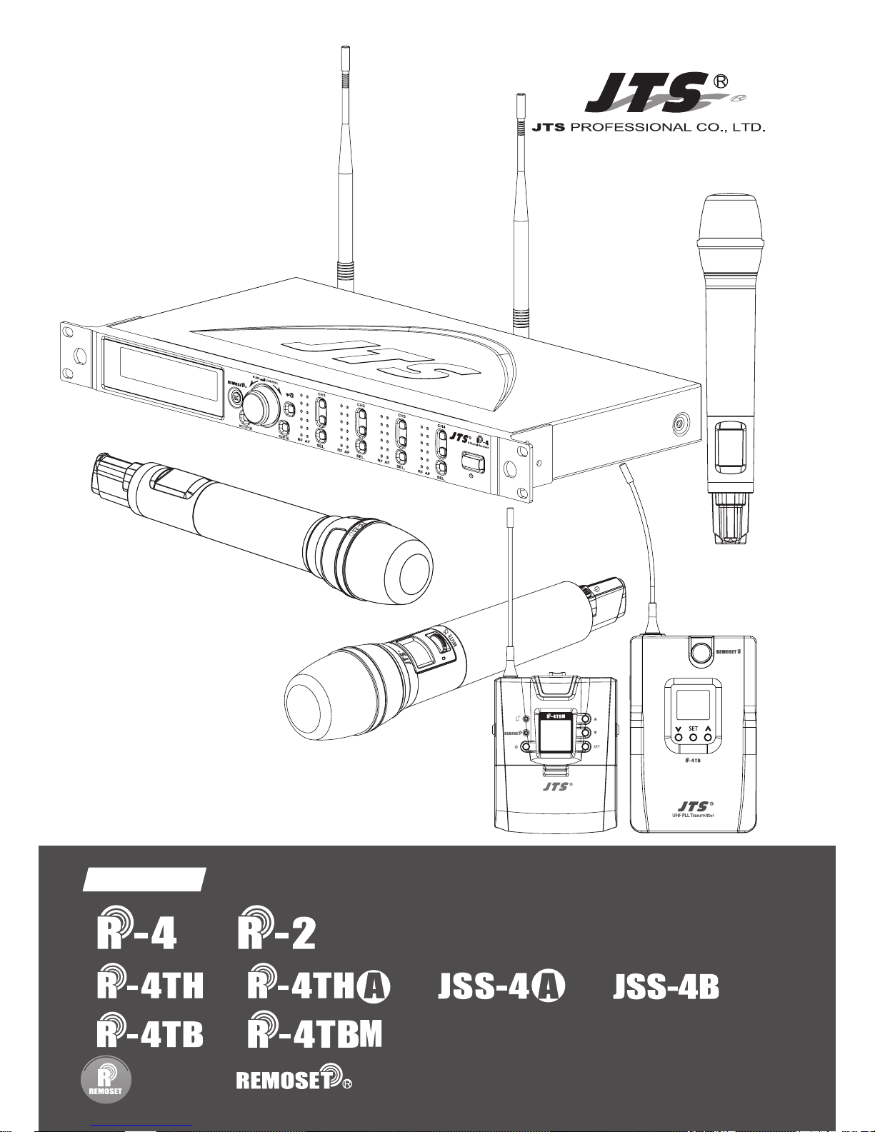
Instruction Manual
UHF PLL
With JTS 2.4G RF Synchronizing Technology
UHF PLL Transmitter
-12dB
IDoff
633.875 MHz
G: 1 C: 11
UF-20TB
AT
Hi

1. The warranty card must be presented with the date of purchase and attached at
the bottom of the machine to ensure the validity of warranty service.
2. The warranty is valid for one year starting from the date of purchase shown on
''warranty label'' attached to the product; alternatively, the warranty is valid for 15
months starting from the date the product was manufactured if the ''warranty label''
is missing on the machine. If the microphone is returned for service but with the
machine, the warranty is valid for 15 months starting from the date of manufacturing
shown on the microphone.
3. If malfunction occurs under normal operations according to the instruction manual
while the warranty is still valid, please call the shop where you purchased the
product for warranty service.
4. It is important to return both the machine and microphone back to the shop for
service, since this makes it easier to identify where the possible problem is and
determine whether a service fee is needed.
5. JTS will provide service free of charge while the warranty is still valid. However, A fee
for parts and/or service may be charged for the following:
a. Damage due to natural disaster or any other irresistible factors;
b. Damage due to dropping, immersion in water, exposure to high humidity,
corrosion, ingress of alien objects, or loss of parts;
c. Consumables are not part of the warranty; or
d. The ''warranty label'' is not found on the machine or the ''warranty label'' is
damaged to the point that the validity of warranty is not recognizable.
6. Keep this warranty card at a safe place, as the warranty is invalid with a lost
warranty card.
One-Year Warranty Card
Product model Serial number
Customer Phone number
Address
Date of purchase
Distributor’s
shop seal
The distributor’s shop seal and date of purchase are
required for the warranty to be valid!
Warranty Service
Contents
1. Notes for system operations
2 . F e a t u r e s
3. Specications
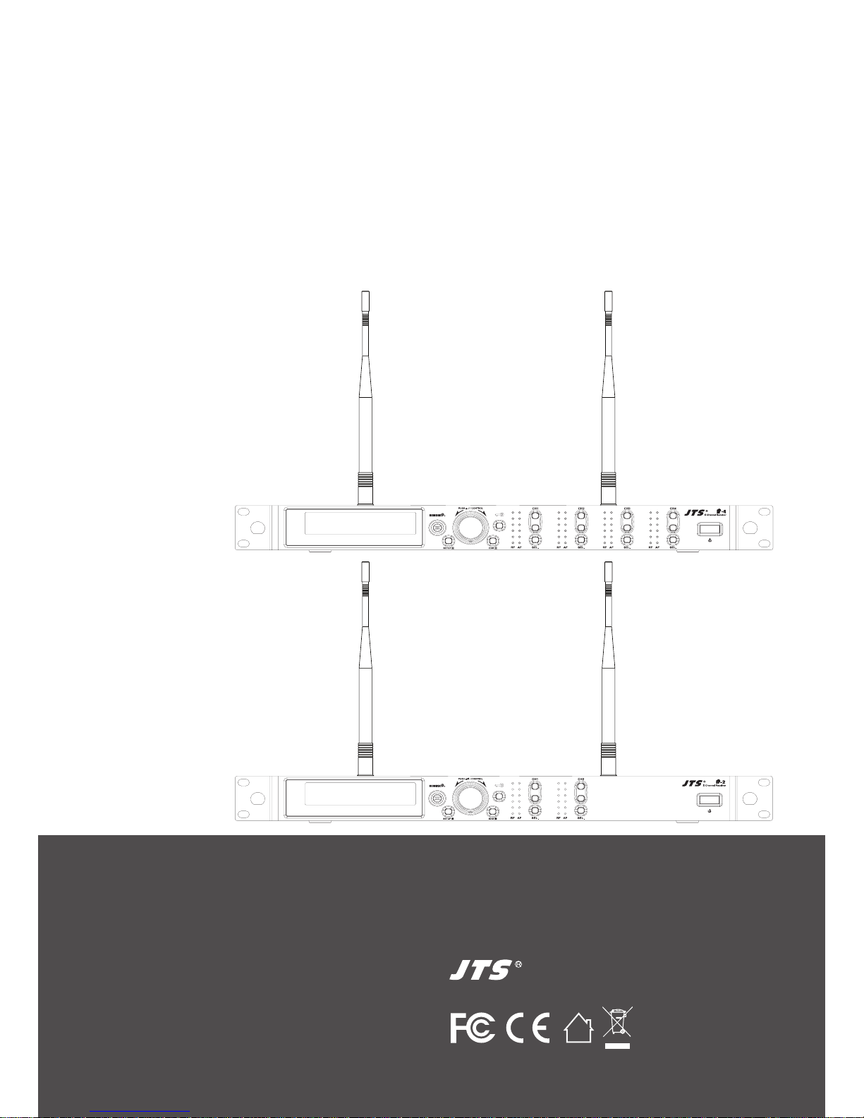
3-1 UHF PLL 4-channel / 2-channel, diversity receiver
3-2 UHF PLL handheld transmitter
3-3 UHF PLL body-pack transmitter
3-4 Optional Condenser Microphon
4. Parts
4-1 UHF PLL 4-channel / 2-channel, diversity receiver // /
4-2 UHF PLL handheld transmitter // /
4-3 UHF PLL handheld transmitter// /
4-4 UHF PLL body-pack transmitter //
4-5 UHF PLL body-pack transmitter //
4-6 Accessories
4-7 Microphone Choices
5. Connection
5-1 Connecting transmitter
5-2 Installing transmitter // /
5-3 Installing transmitter // /
5-4 Installing transmitter //
5-5 Installing transmitter //
6. Operation
6-1 Operation // /
6-2 Operation // /
6-3 Operation // /
6-4 Operation //
6-5 Operation //
7. Digital Code Alert Function
8. Notes for the product
1
1
2
2
3
5
7
9
9
13
15
17
19
21
21
24
24
26
27
27
28
29
29
37
40
46
49
55
56

1
1. Notes for system operations
2. Features
• Before connecting to the main power supply, check that the
power requirements shown on the nameplate of the machine
meet the output of the adaptor.
• Do not place the machine at a place where high temperature
and humidity are expected.
• Do not operate the system with wet hands.
• Keep the machine away from any heat or ignition source.
• Before setting up the machine, make sure that the volume is
set at the minimum for both the mixer and amplier.
• The system features the latest anti-interference digital code
circuit design that is proven to isolate the interference
between the system and the outside world.
• Up to 36MHz of bandwidth with a maximum of 1440 channels
to choose from
• Adjustable squelch level
• Default with 6 groups, up to 22 available
• User-dened groups provided
• Automatic scan
• Provided with antenna booster power
• JTS patent: the latest RF allows the transmission of
not only frequency, but also data such as sensitivity, low cut,
transmission power and key lock to the transmitter.
• With one push of the key, upto four transmitters
can be synchronized.
• RF ''no signal'' alert on LCD display
• AF ''microphone mute'' alert on LCD display
• Transmitter ''low battery'' alert on LCD display
• Antenna and power cascading for improved performance
and convenience.
• Digicode prevents intermodulation
2
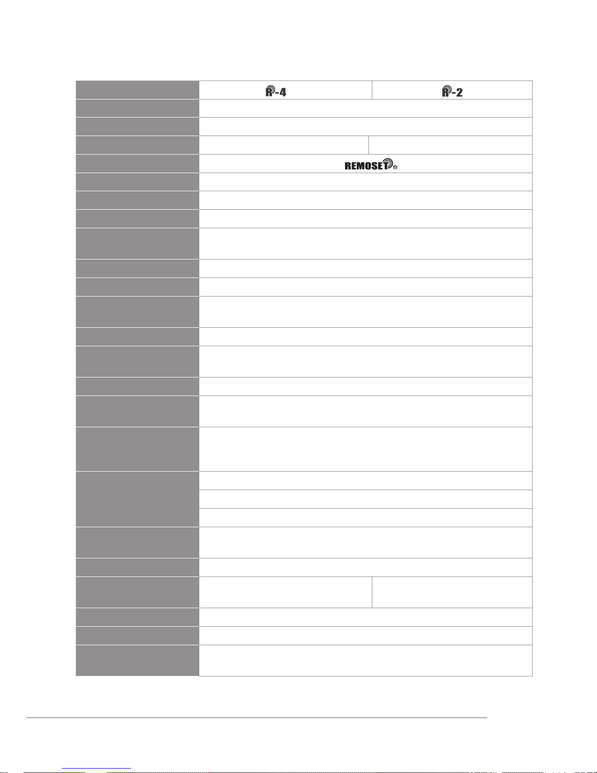
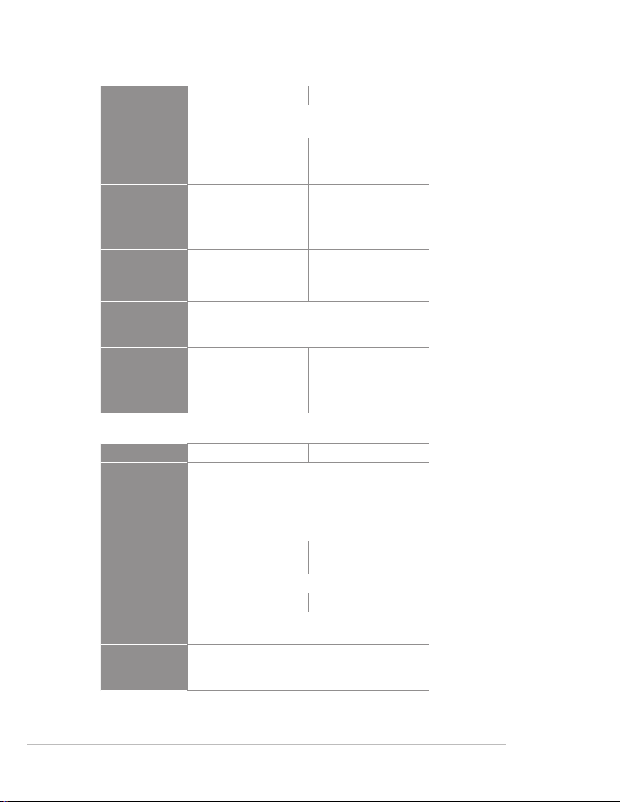
3.Specications
3-1 UHF PLL 4-channel / 2-channel, diversity receiver
Model
Frequency oscillation Phase-locked loop, PLL
Carrier frequency 470~960 MHz
No. of channels 4 channels
2 channels
Channel pairing RF
Diversity antenna diversity
Bandwidth 36MHz
Signal/noise ratio >106dB(A)
Total harmonic
distortion
<0.5%@1KHz
Receiving sensitivity -95dBm,S/N>80dB
Mirror rejection ratio >80 dB
General frequency
response
50Hz~18KHz±2dB
Antenna connector BNC female
Antenna booster
power
DC12V/100mA
Display LCD
Functions displayed
Group, channels, frequency, transmitter power, antenna A/B,
mute, AF, RF, channel scan, output level, volume, Device ID
Controls
Power ON/OFF, groups, channels, frequency, receiving
sensitivity, key lock, volume, output attenuation (XLR),
channel scan (ON/OFF), antenna power, display setting
Audio output level
Ref:±22.5KHz Dev@1KHz Tone
ψ6.3 Phone Jack:-10dBV
XLR Jack:-4dBV(Line)、-24dBV(MIC)
Audio output
impedance
600Ω
Mute Noise mute and Pilot Tone
Output port
5 balance XLR ports,
1 unbalance φ6.3mm jack
3 balance XLR ports,
1 unbalance φ6.3mm jack
Power 100~240VAC
Dimensions 485mm L x 230mm W x 44mm H
Remark
Specications provided above may be slightly different from
the product without further notice.
3
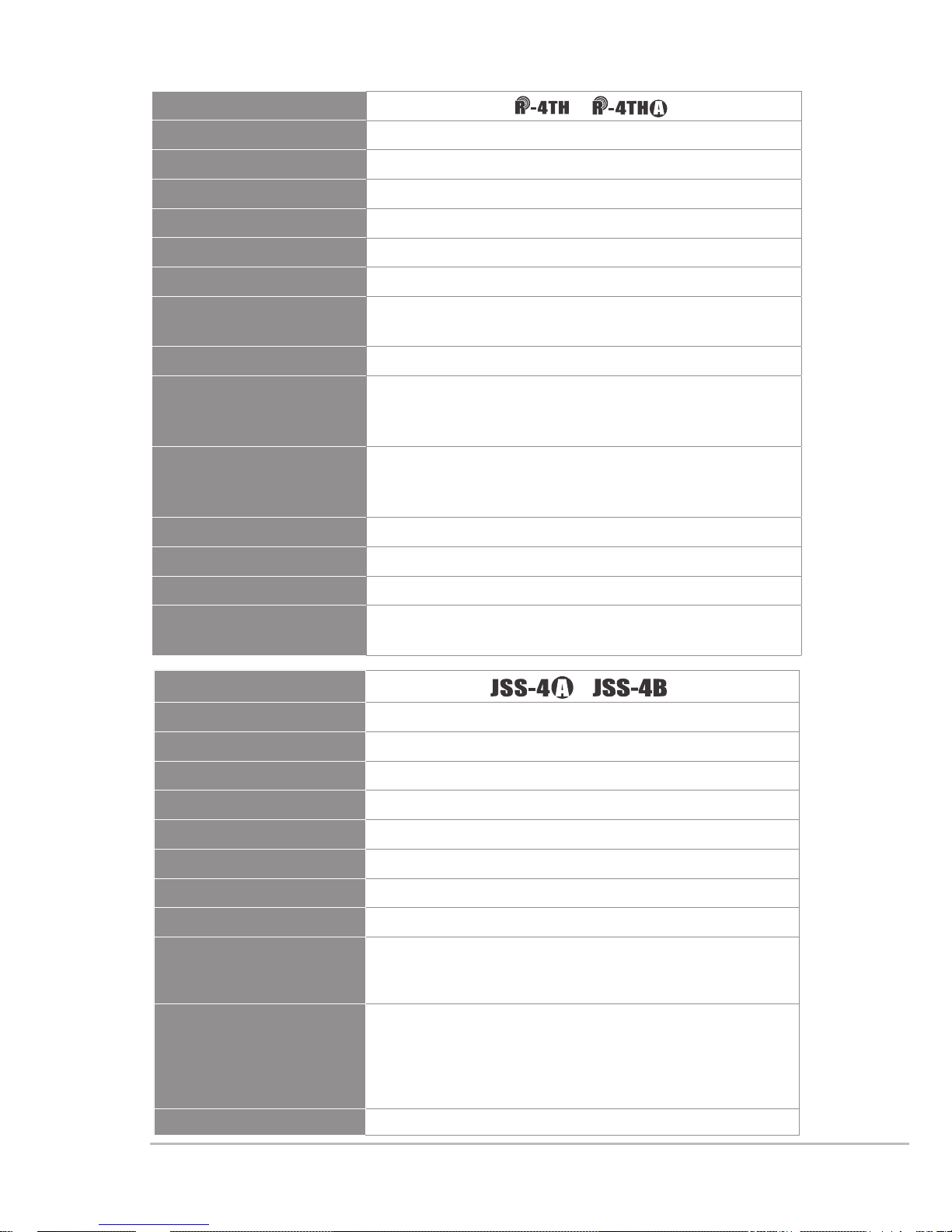
3-2 UHF PLL handheld transmitter
Model /
Frequency oscillation Phase-locked loop, PLL
Carrier frequency 470~960MHz
Bandwidth 108MHz as per local regulation
Paring RF Remoset
RF power output 10mW/50mW(as per local regulation)
RF stability <±10KHz@Fc
Modulation frequency
deviation
±48KHz
Spurious Emissions <-50dBc
LCD display
Group, channels, frequency, mute, auto off, input
level attenuation, sensitivity adjustment, power
indication, Device ID
Controls
Power, mute, groups, channels, frequency,
sensitivity adjustment, input level attenuation,
auto off, transmission power, key lock
Battery AA Alkaline battery x 2
Charging Yes
Dimension
265mm L x 51.2mm W x 51.2mm H
Remark
Specications provided above may be slightly
different from the product without further notice.
Model
/
Frequency oscillation Phase-locked loop, PLL
Carrier frequency
UHF 470~960 MHz
Bandwidth 108 MHz as per local regulation
Pairing RF Remoset
RF power output 10mW / 50mW (as per local regulation)
RF output
Hi / Lo adjustable
Stability
<0.005%
Frequency deviation
±48kHz
LCD display
Group and channel, frequency, power indication,
transmission power, sensitivity, Device ID, username,
gain, low cut
Controls
Power ON/OFF, frequency setting, group, sensitivity,
bass attenuation, pairing ID, frequency pairing,
transmission power adjustment, display contrast,
backlight time setting, Chinese/English selection, key
lock pattern, mute, reset
Harmonic radiation <-50 dBC

4
Audio frequency
response
50KHz~18KHz
Capsule Module
Interchangeable
Battery AA Alkaline battery x 2 / rechargeable battery x 2
Charger CH-2,CH-8
Dimensions
35.5mm L x 50mm W x 253mm H
Remark
Specications provided above may be slightly
different from the product without further
notice.
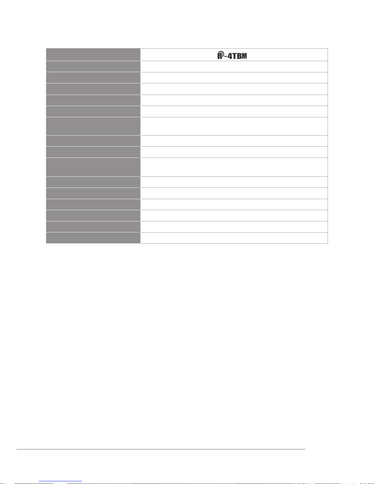
5
Model
Frequency oscillation Phase-locked loop, PLL
Carrier frequency 470~960MHz
Bandwidth 108MHz as per local regulation
Paring RF Remoset
RF power output 10mW/50mW(as per local regulation)
RF stability <±10KHz
Modulation frequency
deviation
±48KHz
(Peak)
Spurious Emissions <-50dBc
LCD display
Group, channels, frequency, mute, auto off, input level
attenuation, sensitivity adjustment, power indication,
Device ID
Controls
Power, mute, groups, channels, frequency, sensitivity
adjustment, input level attenuation, auto off, transmission
power, key lock
Input connector 4-pin mini XLR
Controls
Power, mute, group, channel, frequency, sensitivity
adjustment, input level attenuation, auto off
Battery AA Alkaline battery x 2
Charger CH-2 CH-8
Dimension
62.3mm L x 20mm W x 97mm H
Remark
Specications provided above may be slightly different
from the product without further notice.
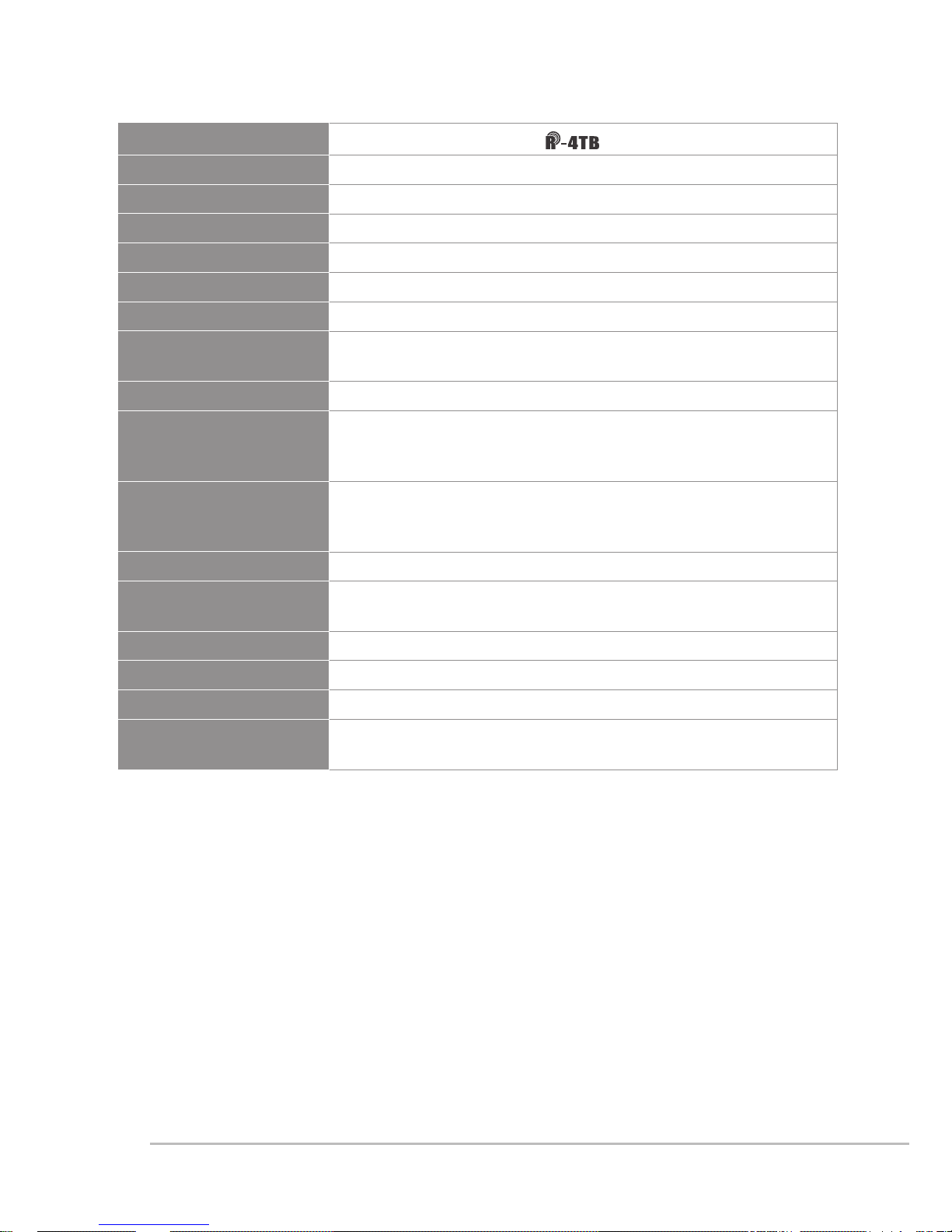
3-3 UHF PLL body-pack transmitter
6
Model
Frequency oscillation
PLL Synthesized Control
Carrier frequency
UHF 470~960 MHz
Bandwidth
108MHz as per local regulation
Rf power outputs
Low / High
RF stability
<±10KHz
Modulation frequency
deviation
±48KHz (Peak)
Chassis
Aluminium alloy
Lcd display
Group, Channel, Frequency, Battery Status, GAIN Adjust
Controls
Power ON/OFF, AF Level, Frequency (Up/Down), Lock-on
Mode, REMOSET ID, RF Output Adjust
Input connector
4P Mini XLR
Spurious emissions
<-50 dBC
Audio frequency response
50Hz~18k Hz
Battery
AA NiMH x2
Dimension
62mm W x 80.3mm H x 22.6mm D
Weight
93g
7
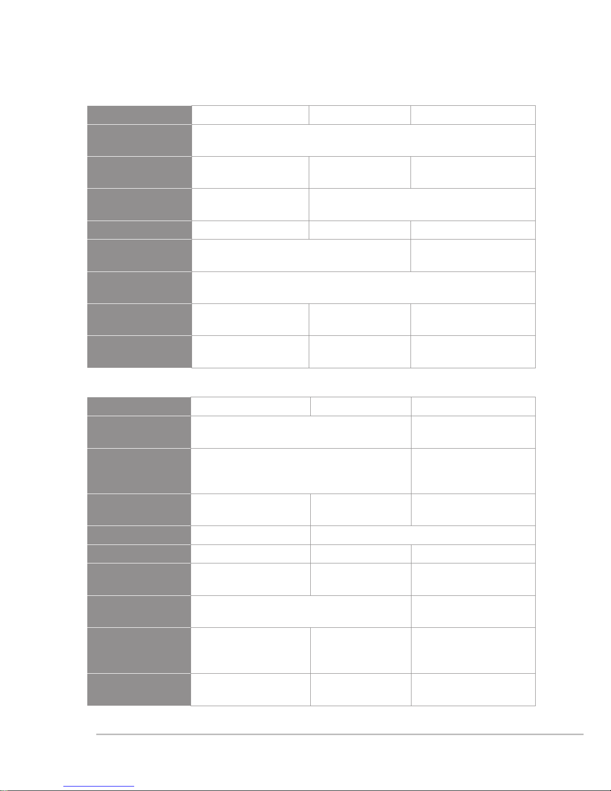
3-4 Optional Condenser microphone
Lavaliere microphone
Headset microphone
Model CM-501 CM-201i CM-125i
Output
connector
4-pin mini XLR
Frequency
response
100~15,000 Hz 60~15,000 Hz 50~18,000 Hz
Directionality
Cardioid
directionality
Omni-directionality
Sensitivity -60 ± 3dB -60 ± 3dB -53 ± 3dB
Output
impedance
2.2K Ω 4.4K Ω
Max. sound
pressure allowed
130dB
Dimension (mm)
Ø
10.1mm
W
x
26.4mm
H
Ø
5mm
W
x 9mm
H
Ø
4mm
W
x 11mm
H
Weight
21.5g 20.7g 7g (cable not
included)
Model CM-214i CM-214Ui CM-214ULi
Output
connector
4-pin mini XLR 4P/3P mini
XLR/3.5stereo jack
Output
connector
(optional)
3P Mini XLR/3.5 stereo plug/4P Hirose
jack
4P Hirose jack
Frequency
response
60~15,000 Hz 30~18,000 Hz 100~18,000 Hz
Directionality Omni-directionality Cardioid directionality
Sensitivity -60 ± 3dB -68 ± 3dB -75 ± 3dB
Output
impedance
1.8kΩ 680Ω 1.8kΩ
Max. sound
pressure allowed
130dB 120dB
Dimension (mm)
157mm L x
125mm W x
134mm H
157mm L x
205mm W x
134mm H
157mm L x
125mm W x
134mm H
Weight
32.9g 38.4g 18g (cable not
included)
8
Ear-hook microphone
Model CM-235i CX-504
Output
connector
4P-pin mini XLR
Output
connector
(optional)
3P Mini XLR/3.5 ste-
reo plug/4P Hirose
jack
Frequency
response
50~18,000 Hz 30~18,000 Hz
Directionality
Omni-directionality Cardioid
directionality
Sensitivity -53 ± 3dB -68 ± 3dB
Output
impedance
1.8kΩ 680Ω
Max. sound
pressure
allowed
130dB
Dimensions
(mm)
157mm L x
155mmWx
134mmW
111.3mm L x
285mmWx
55mmW
Weight 17g 56.3g
Model CM-801 / CM-804i CM-8015 / CM-825i
Output
connector
4-pin mini XLR
Output
connector
(optional)
3P Mini XLR/3.5 stereo plug/4P Hirose jack
Frequency
response
60~15,000 Hz 50~18,000 Hz
Directionality Omni-directionality
Sensitivity -64 ± 3dB -53 ± 3dB
Output
impedance
1.8KΩ
Max. sound
pressure
allowed
130dB
9
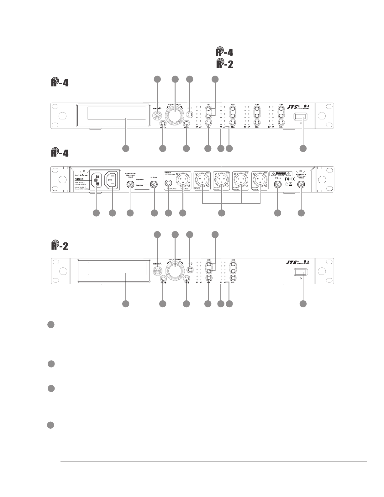
4. Parts
1
4
2
3
Power ON/OFF:ON:push once to turn on
OFF:push and hold until ''Power OFF'' is shown on the
LCD to turn off.
EXIT:Push exit to cancel a selection or exit from the current menu when
R-4/2 is in the ''setting menu.''
Rotary Switch:when in the ''function menu,'' turn the switch to select the
desired function; push the switch (or SETUP) to enter the selection and
spin the switch to select the setting. Push [SETUP] to save the setting.
SETUP:Push and hold for 2 seconds to enter the vsetting menu.'' Push
SETUP to save the setting once the selection and setting are made
according to ''3. Rotary Switch.''
Front panel
Rear panel
9
9
11
11
1
1
3
3
2
2
5
5
7
7
4
4
8
8
6
6
4-1 UHF PLL 4-channel diversity receiver //
10
10
Front panel
UHF PLL 2-channel diversity receiver //
14
16 1617 1715 14a
13
12

10
9
5
6
7
8
REMOSET:When the receiver setting is done, push to
transmit the setting data to the handheld or body-pack transmitter.
LCD display:See ''Receiver LCD display instructions.''
AF: indicates the current strength of audio frequency signals.
RF: indicates the current strength of radio frequency signals.
Key lock: push and hold for 2 seconds to lock all keys, and again to unlock.
Volume keys:push▲/▼keys to adjust the volume between 0 and -31dB.
Selection key:push this button
a. Push SETUP to enter the setting for the selected channel for parameter
settings.
b. Push REMOSET to transmit the setting data to the transmitter in this
selected channel.
AC Power Jack:connects 100-240VAC power.
AC power cascading:use AC double power cable (optional) for power
cascading.
XLR audio jack:balanced audio signal output
XLR audio jack:balanced audio signal output after mixing
Ø6.3 audio output jack:unbalanced audio signal output after mixing
Antenna A (B) input terminal:BNC antenna input jack that also provides
DC12V/100mA output.
RF signal A (B) output terminal: RF signal output jack; it is possible to
connect the RF A (or B) OUT of the rst unit to the antenna A (or B) IN of
the second unit with a BNC-BNC signal cable, and then the RF A (or B)
OUT of the second unit to the antenna A (or B) IN of the third unit, and so
on and so forth. The cascade may consist of up to 10 units to minimize the
number of antennas used.
10
11
12
13
14
14a
15
16
17
Note: Each cascading may bring1.2dB attenuation to RF signal.
11
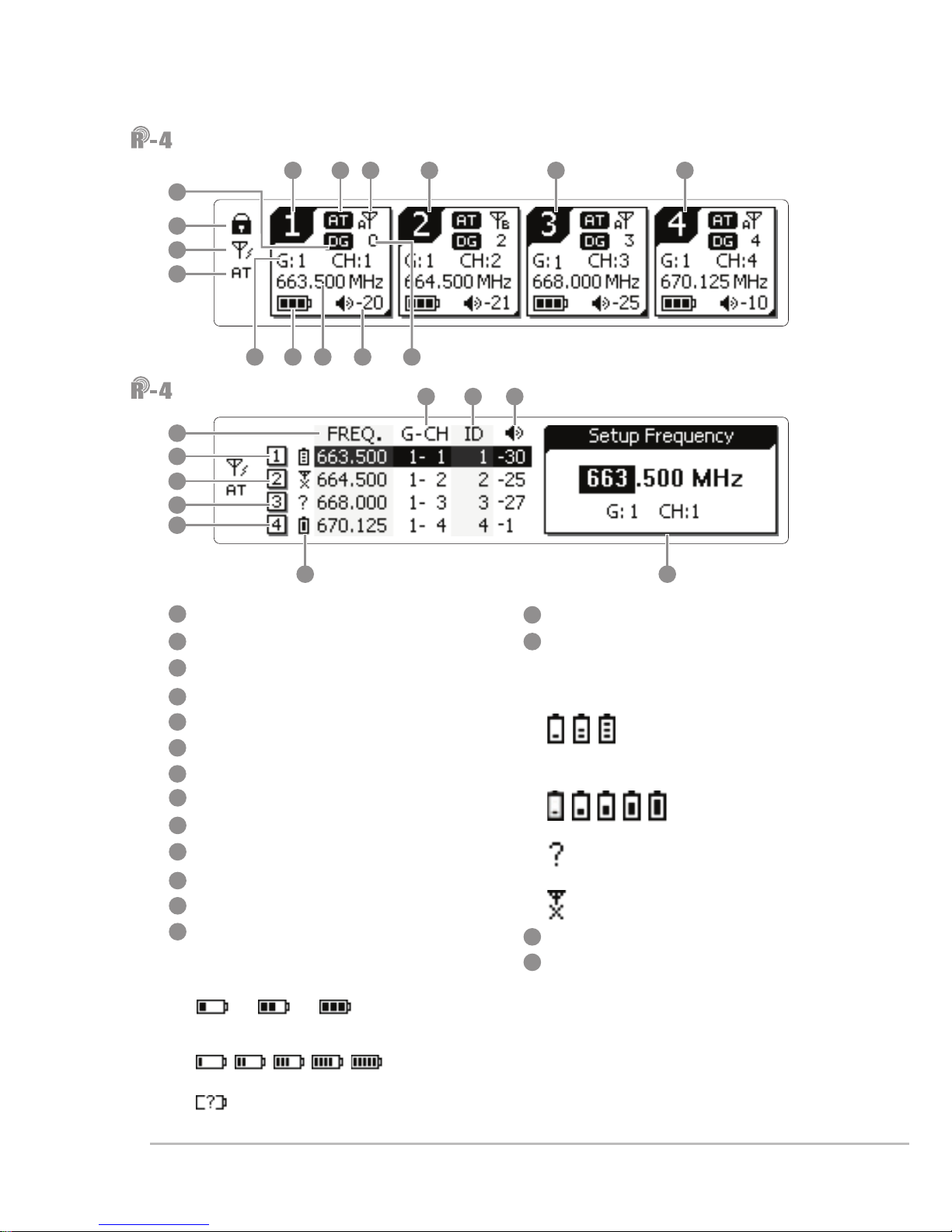
LCD displays
Setting page
Key lock
Antenna power supply ON
Mixed output attenuation ON
Receiver channel 1
Receiver channel 2
Receiver channel 3
Receiver channel 4
Output attenuation ON
Antenna selection A/B
Device ID
Group/channel
Frequency
Transmitter battery
3blocks: R-4TH/R-4THA/R-4TB
microphone is used
5blocks: JSS-4A microphone is used
:waiting for battery
information from transmitter
Volume
Transmitter battery
3blocks: R-4TH/R-4THA/R-4TB
microphone is used
5blocks: JSS-4A microphone is used
:waiting for battery information
from transmitter
:no microphone signal
Setting window
Digital code ON
18
33
25
19
26
20
27
21
28
22
29
23
30
24
31
32
21
2930 31
3128 27
28
25 26
27
22 23 24
18
20
19
29
21
22
23
24
32 33
34
34
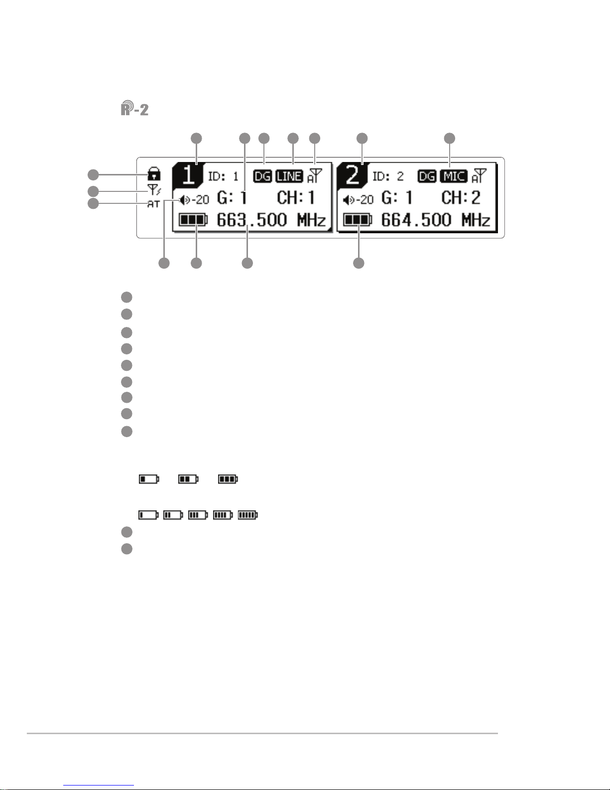
12
LCD displays
Key lock
Antenna power supply ON
Mixed output attenuation ON
Receiver channel
Digital code ON
Output level LINE/MIC
Antenna selection A/B
Volume
Transmitter battery
3blocks: R-4TH / R-4THA/R-4TB
microphone is used
5blocks:JSS-4A microphone is used
Group / channel
Frequency
38 39 40 41 38 4044
42
35
36
37
43 4345
41
35
42
36
43
37
44
45
38
39
40

13
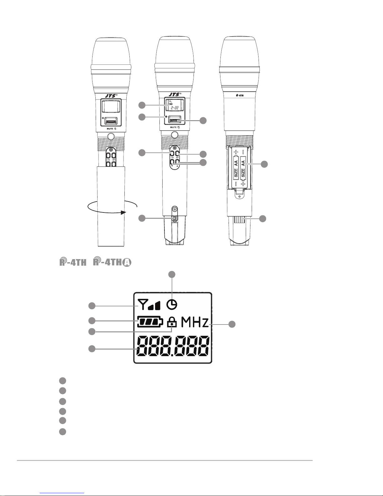
Power ON/OFF:push once to turn on. Push and hold for 2 seconds while
the power is on to turn off. While the power is on, a quick push of this
button will show the Device ID on the LCD display.
Mute:switch up to talk and down to mute while the power is on. If the
power is off, switching up from mute will turn the microphone on. In
mute, it is allowed to select 1, 10 or 30 minutes to automatically turn the
microphone off.
Battery compartment:it holds 2 UM3, AA 1.5V Alkaline batteries or MiNH
rechargeable batteries.
LED indicator:it shows the microphone's status, including battery power,
mute and pairing.
LCD display:it shows the parameter settings of transmitter.
SET:for parameter settings, including frequency, group, channel,
sensitivity, transmission frequency, auto off time, Device ID ,
function (ON/OFF).
Up/down selection keys:they are used with ''SET'' to change parameter
settings. Before entering the setting mode, a quick push will show the
Device ID on the LCD display.
LOCK :push and hold ''LOCK'' for 2 seconds to lock and again to un-
lock. Under ''LOCK'' status MUTE function is still valid.
Charging contact module: if rechargeable batteries are used, charging is
possible with the matching charger.
4-2 UHF PLL handheld transmitter // /
Note:R-4TH is the same as R-4THA except that the battery cover of the R-4THA is made of
metal.
1
4
2
3
9
5
6
7
8
14
RF output power (1 block is 10mW and 2 blocks are 50mW)
Auto off ON
Battery level
Key lock
Frequency (MHz)
Indication of frequency, group and channel
/ LCD displays
1
4
2
3
9
5
6
7
8
10
10
11
11
12
12
13
13
14
14
15
15

15
4-3 UHF PLL handheld transmitter // /
LCD display
SET:for handheld transmitter setting and saving
▲、▼:up and down; used to select the desired item for handheld
transmitter.
Power ON/OFF
(1)Turn the handheld transmitter on
Power on: push the button once to turn on
Power off: push and hold for 1 second until the LCD display shows
''power off.''
(2)Mute:while the handheld transmitter is in use (main page on the
LCD display)
Mute:push the Power ON/OFF and the display shows ''mute.''
Unmute: push the Power ON/OFF again and the display shows
''unmute.''
(3)Exit setting menu
In the setting menu: push Power ON/OFF to return to main page.
In the function setting menu: push Power ON/OFF to return to the
setting menu, and again to return to main page.
Battery compartment
Charging contact: used with the charger (optional for CH-2 or CH-8)
Slide cover
Detachable capsule module
LED status indication
Green: Power ON
Blue: Remoset done (on for about 5 seconds)
Red: battery low
Blinking red: mute
Blinking red/green: battery low and mute
1
4
2
3
9
5
6
7
8
 Loading...