

Page 1
Instruction Manual
UHF PLL
WIRELESS SYSTEMS
US-901D/US-9001D
Mh-950/Mh-960/Mh-8900(i)/PT-950B(mi)
59506-048-04
US-901D
US-9001D
Page 2

ank you for choosing the JTS wireless system. In order to obtain the best eciency from the system,
you are recommended to take few minutes to read this instruction manual carefully.
1. Important Caution
2. Features
3. Specication
3-1 Receiver// US-901D US-9001D
3-2 Handheld Transmitter // Mh-950 Mh-960 Mh-8900(i)
3-3 Body-pack Transmitter // PT-950B(mi)
3-4 Optional Condenser Microphone
4. Part Identication & Accessories
4-1 Receiver // US-901D US-9001D
4-2 Handheld Transmitter // Mh-950 Mh-960 Mh-8900(i)
4-3 Body-pack Transmitter // PT-950B(mi)
4-4 Optional Condenser Microphone
4-5 Accessories
5. Preparing Procedures & Basic Operation
5-1 Receiver// US-901D US-9001D
5-2 Handheld Transmitter // Mh-950 Mh-960
5-3 Handheld Transmitter // Mh-8900(i)
5-4 Body-pack Transmitter // PT-950B(mi)
6. Recommendation
7. Important Notice
1
1
2
2
3
4
4
7
7
8
9
10
14
15
15
18
20
22
26
27
INDEX
Page 3

WIRELESS MICROPHONE SYSTEM
1
2
1. Important Caution
2. Features
Always make all connections before plugging the unit into an AC power outlet. •
Do not leave the devices in a place neither with high temperature nor high humidity.•
Always do not handle the power cord with wet hands !•
Keep the devices away from re and heat sources. •
Operated in UHF band where there is less RF interference than the VHF band. •
Due to the PLL synthesized technology, the system can oer up to 193 selectable frequencies for •
choosing simultaneously.
e true diversity reception with 2 independent RF receivers ensure the stable transmission and •
reception.
Adjustable Pilot tone squelch control can eectively reduce the noise. •
Equipped with S.A.W. lter benets the interference-resistant. •
Tuned antennas can benet the stable RF reception.•
Built-in Noise Squelch circuity & Mute function are available to restrain the interference for •
signals.
Compact half-rack receiver design is considerable for the space saving.
•
Rugged metal housing can pass through the dicult environment. •
Equipped with balanced XLR and unbalanced output allow great convenience.•
Anti-interference design is available to work with every computer device.•
3. Specication
3-1 Receiver // US-901D US-9001D
Frequency Preparation......
Carrier Frequency Range
S/N Ratio...................................
T.H.D..................................
Display..............................
Display Contents...................
Controls............................
Audio Output Level............
AF Output Impedance......
Squelch.............................
Operation Voltage.................
Output Connector................
Dimension(m/m)...............
PLL Synthesized Control
502~960 MHz
> 105dB
<0.6%@1KHz
LCD
Frequency, Antenna A/B, Mute Display, RF/AF Level Meter,
Baery Fuel Gauge
Power On/O, Frequency Up/Down, Frequency
Scan, Audio Level, Lock-on
-12dB
600Ω
Pilot Tone & Noise Mute
12-18 VDC, 200 mA
1 XLR Balanced Socket
1 Ø6.3mm Unbalanced phone jack
US-901D: 212mm (W)* 40mm (H)* 125mm (D)
US-9001D: 212mm (W)* 40mm (H)* 137mm (D)
Page 4

WIRELESS MICROPHONE SYSTEM
3
4
3-2 Handheld Transmitter // Mh-950 Mh-960
Handheld Transmitter // Mh-8900(i)
Frequency Preparation............
Carrier Frequency Range......
RF Outputs.....................................
Stability...............................................
Frequency Deviation................
LCD Display...................................
Controls.............................................
Spurious Emissions...................
Audio Frequency Response
Baery..................................................
PLL Synthesized Control
502~960 MHz
10mW
±10KHz
±48KHz
Frequency, Baery Fuel Gauge, Sensitivity
Power On/O, Mode Seing, AF Level,
Frequency Up/Down, Lock-on Mode
<-50 dBC
50~16,000 Hz
UM3, AA 1.5V*2
Frequency Preparatio................
Carrier Frequency Range......
RF Outputs......................................
Stability................................................
Frequency Deviation................
LCD Display...................................
Controls.............................................
Spurious Emissions....................
Audio Frequency Response
Baery..................................................
PLL Synthesized Control
502~960 MHz
10mW
±10KHz
±48KHz
Frequency, Baery Fuel Gauge, Sensitivity
Power On/O, Mode Seing, AF Level,
Frequency Up/Down, Lock-on Mode
<-60 dBC
50~16,000 Hz
UM3, AA 1.5V*2
3-3 Body-pack Transmitter // PT-950B(mi)
Frequency Preparation............
Carrier Frequency R ange......
RF Outputs......................................
Stability.................................
Frequency Deviation................
LCD Display...................................
Controls................................
Output connector........................
Spurious Emissions...................
Audio Frequency Response
Battery...................................
PLL Synthesized Control
502~960 MHz
10mW
±10KHz
±48KHz
Frequency, Baery Fuel Gauge
Power On/O, AF Level,
Frequency Up/Down, Lock-on Mode
4P Mini XLR
<-50 dBC
40~18,000 Hz
UM3, AA 1.5V*2
3-4 Optional Condenser Microphone
Model No...............................
Connector..............................
Frequency Response......
Polar Paern..........................
Sensitivity (at 1000Hz)
Impedance.............................
Max. SPL for 1% THD
Dimension(mm)..............
Net Weight............................
CM-501
4P Mini XLR
100~15,000 Hz
Cardioid
-60±3 dB
2.2kΩ
130dB
Ø10.1mm(W)
* 26.4mm(H)
21.5g
CM-201
4P Mini XLR
60~15,000 Hz
Omni-directional
-60±3 dB
2.2kΩ
130dB
Ø5mm(W)*
9mm(H)
20.7g
CM-125
4P Mini XLR
50~18,000 Hz
Omni-directional
-53±3 dB
4.4kΩ
130dB
Ø4mm(W)*
11mm(H)
7g (cable excluded)
Lavaliere Microphone // CM-501 CM-201 CM-125
Page 5

WIRELESS MICROPHONE SYSTEM
5
6
Headset Microphone // CM-214 CM-214U CM-214UL CM-235 CX-504
Ear-hook Microphone // CM-801 CM-804i CM-8015 CM-825i
Compatible Instrument Microphone // CX-500 CX-500F CX-520
CX-508W CX-516W
Model No...............................
Connector..............................
Frequency Response......
Polar Paern..........................
Sensitivity (at 1000Hz)
Impedance.............................
Max. SPL for 1% THD
Dimension(mm)..............
Net Weight............................
CM-235
801C4 (4P Mini XLR)
50~18,000 Hz
Omni-directional
-53±3 dB
1.8kΩ
130dB
155mm(W)
* 134mm(H)
* 157mm(D)
17g (cable excluded)
CX-504
4P Mini XLR
30~18,000 Hz
Cardioid
-68±3 dB
680Ω
130dB
285mm(W)
* 55mm(H)
* 111.3mm(D)
56.3g
Model No...............................
Connector...............................
Option Connector...........
Frequency Response......
Polar Paern..........................
Sensitivity (at 1000Hz)
Impedance.............................
Max. SPL for 1% THD
Dimension(mm)..............
Net Weight............................
CM-214
801C4
(4P Mini XLR)
801C3 (3P Mini XLR)
801CS (3.5 stereo plug)
801CR
60~15,000 Hz
Omni-directional
-60±3 dB
1.8kΩ
130dB
125mm(W)
* 134mm(H)
* 157mm(D)
32.9g
CM-214U
4P Mini XLR
30~18,000 Hz
Cardioid
-68±3 dB
680Ω
130dB
205mm(W)
* 134mm(H)
* 157mm(D)
38.4g
CM-214UL
801C3 (3P Mini XLR)
801C4 (4P Mini XLR)
801CS (3.5 stereo plug)
801CR
100 ~ 18,000Hz
Cardioid
-65±3 dB
1.8kΩ
120dB
125mm(W)
* 134mm(H)
* 157mm(D)
18g (cable excluded)
Model No...............................
Connector..............................
Option Connector...........
Frequency Response......
Polar Paern..........................
Sensitivity (at 1000Hz)
Impedance.............................
Max. SPL for 1% THD
CM-801/CM-804i
801C4 (4P Mini XLR)
801C3 (3P Mini XLR)
801CS (3.5 stereo plug)
801CR
60~15,000 Hz
Omni-directional
-64±3 dB
1.8kΩ
130dB
CM-8015/CM-825i
801C4 (4P Mini XLR)
801C3 (3P Mini XLR)
801CS (3.5 stereo plug)
801CR
50~18,000 Hz
Omni-directional
-53±3 dB
1.8kΩ
130dB
Model No...............................
Connector..............................
Frequency Response......
Polar Paern..........................
Sensitivity (at 1000Hz)
Impedance.............................
Max. SPL for 1% THD
Good For.................................
Model No...............................
Connector..............................
Frequency Response......
Polar Paern..........................
Sensitivity (at 1000Hz)
Impedance.............................
Max. SPL for 1% THD
Good For.................................
CX-500
4P Mini XLR
20~20,000 Hz
Omni-directional
-58±3dB
1.5kΩ
130 dB
Violin
CX-508W
4P Mini XLR
50~18,000 Hz
Cardioid
-67±3 dB
220Ω
130 dB
Winds
CX-500F
4P Mini XLR
20~20,000 Hz
Omni-directional
-58±3dB
1.5kΩ
130 dB
Flutes
CX-520
4P Mini XLR
50~16,500 Hz
Supercardioid
-78±3dB
600Ω
148 dB
Harmonica
CX-516W
4P Mini XLR
30~18,000 Hz
Cardioid
-67±3 dB
220Ω
130 dB
Accordion
Page 6
WIRELESS MICROPHONE SYSTEM
7
8
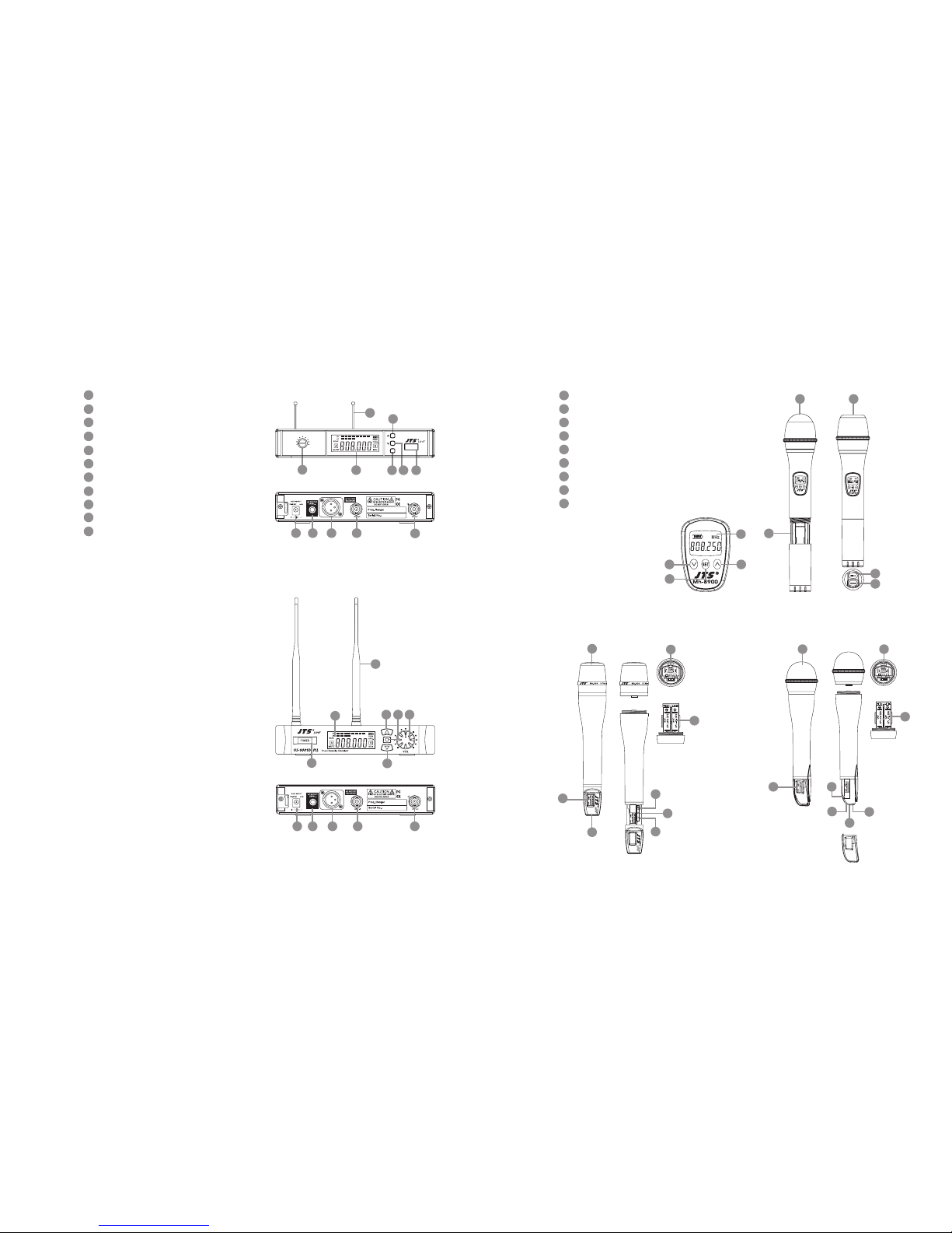
4. Parts Identication & Accessories
4-1 Receiver // US-901D US-9001D
Power On/O switch
Up buon (frequency adjustment)
Down buon (frequency adjustment)
Set buon (frequency adjustment)
LCD Display
Volume control
DC socket for connection of main unit
AF output, jack socket (AF UNBAL)
Balanced XLR socket
Antenna input socket
Antenna
1
4
7
10
11
Interchangeable dynamic capsule
LCD display
Down buon
UP buon
Set buon
Baery tray buon
Baery tray
Power On/O switch
Mute On/O switch
4-2 Handheld Transmitter // Mh-8900(i) Mh-950 Mh-960
12
15
13
16
18
14
17
19
20
2
5
8
3
6
9
14
11
2
5
3
6
200
1856
POWER
SET
MIN. MAX.
DIVERSITY RECEIVER
US-901D
7
10
108 9
Mh-950
200
1856
1
4112
5
3
6
7 10
108 9
13
1514
16
Mh-960
17
12
18
13 14
15
19
16
Mh-8900i
12 12
19
18
20
Mh-8900i Mh-8900
17
12
18
13
14
16
15
19
Page 7
WIRELESS MICROPHONE SYSTEM
9
10
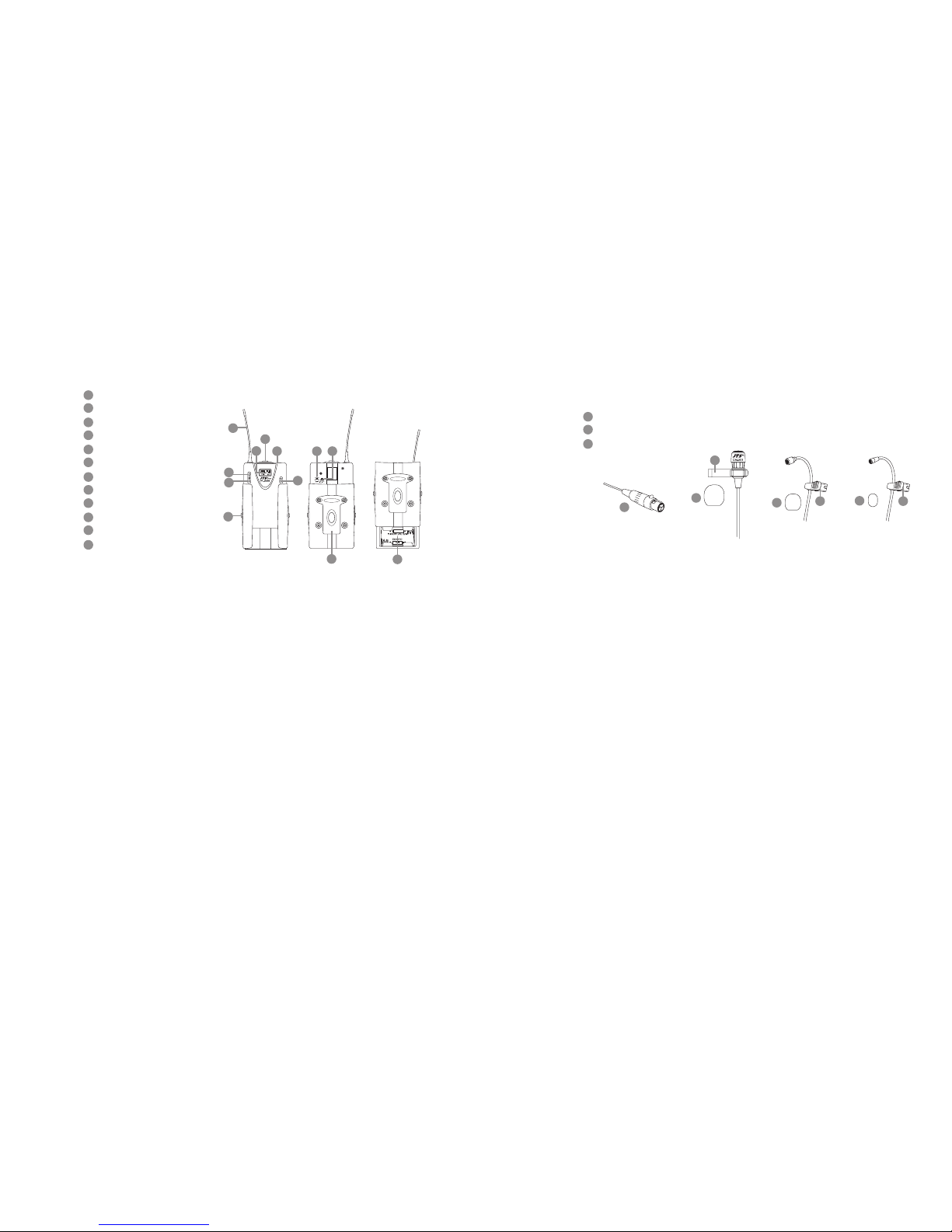
Mic. input
Power On/o switch
Antenna
LCD display
Set buon
Up buon
Down buon
Baery tray buon
AF level control
Belt clip
Baery tray
Aenuation pad(PT-950Bmi)
4-3 Body-pack Transmitter // PT-950B(mi)
21
23
25
30
27
32
22
24
29
26
31
28
Clip
4 Pin Mini XLR
Windscreen
33
35
34
4-4 Optional Condenser Microphone
Lavaliere Microphone // CM-501 CM-201 CM-125
CM-501 CM-201 CM-125
35
35
35
34
33
33 33
21
23
30
32
22
29
31
28
25
27
24
26
Page 8
WIRELESS MICROPHONE SYSTEM
11
12
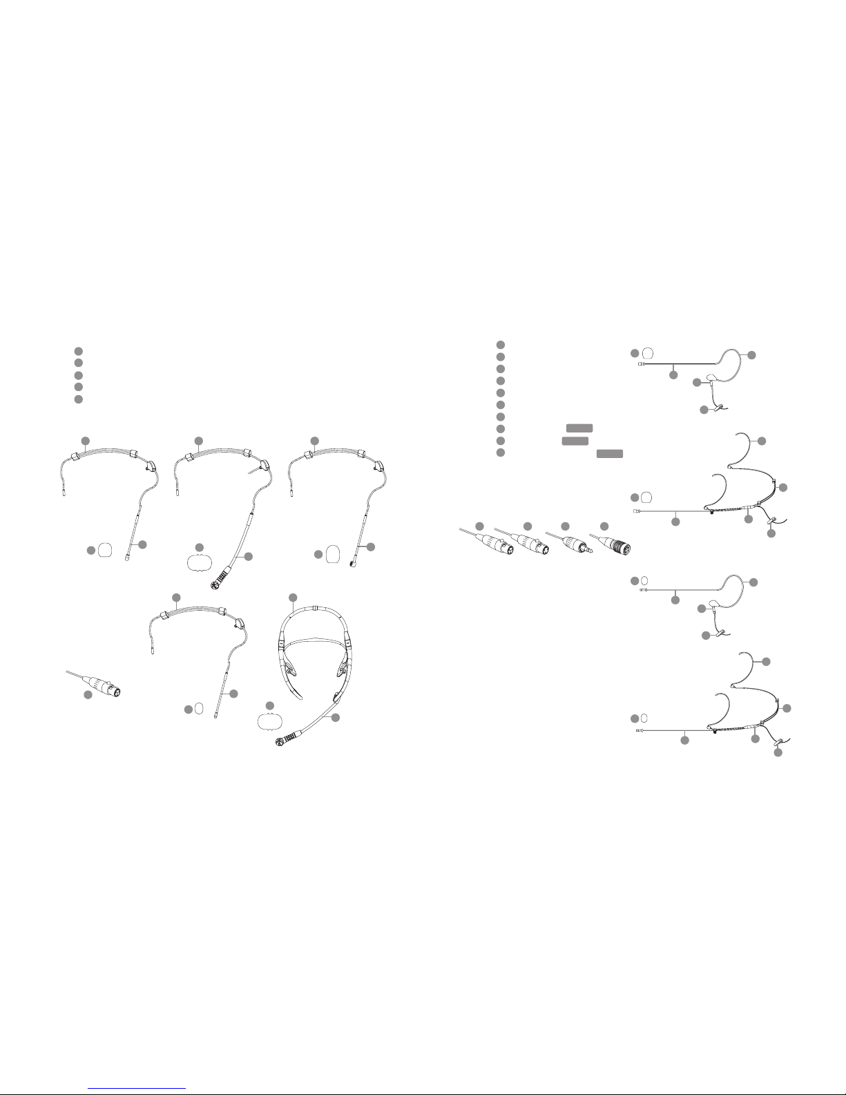
Gooseneck
Adjustable headband
Headband
4 Pin Mini XLR
Windscreen
36
38
39
40
37
Headset Microphone // CM-214 CM-214U CM-214UL CM-235 CX-504
Ear-hook Microphone // CM-801 CM-804i CM-8015 CM-825i
CM-214 CM-214U
CM-235 CX-504
37 37
37
37
38
40
40
40
40
40
36
36
36
36
36
39
CM-214UL
Standard :
4 Pin Mini XLR
3 Pin Mini XLR
3.5 Stereo Plug
Boom
Adjustable Headband
Adjustable ear hook
Detchable Cable
Cable Clip
Windscreen
4 Pin Mini XLR
3 Pin Mini XLR
3.5 Stereo Plug
4Pin Hirose connecter
46
48
48
47
49
50
49
43
45
47
44
41
42
CM-825i
45
46
41
43
44
42
Option
Option
Option
CM-801
45
46
41
43
44
CM-804i
45
46
41
43
44
42
CM-8015
45
46
41
43
44
50
Page 9
WIRELESS MICROPHONE SYSTEM
13
14
Compatible Instrument Microphone // CX-500 / CX-500F / CX-520 /
CX-508W / CX-516W
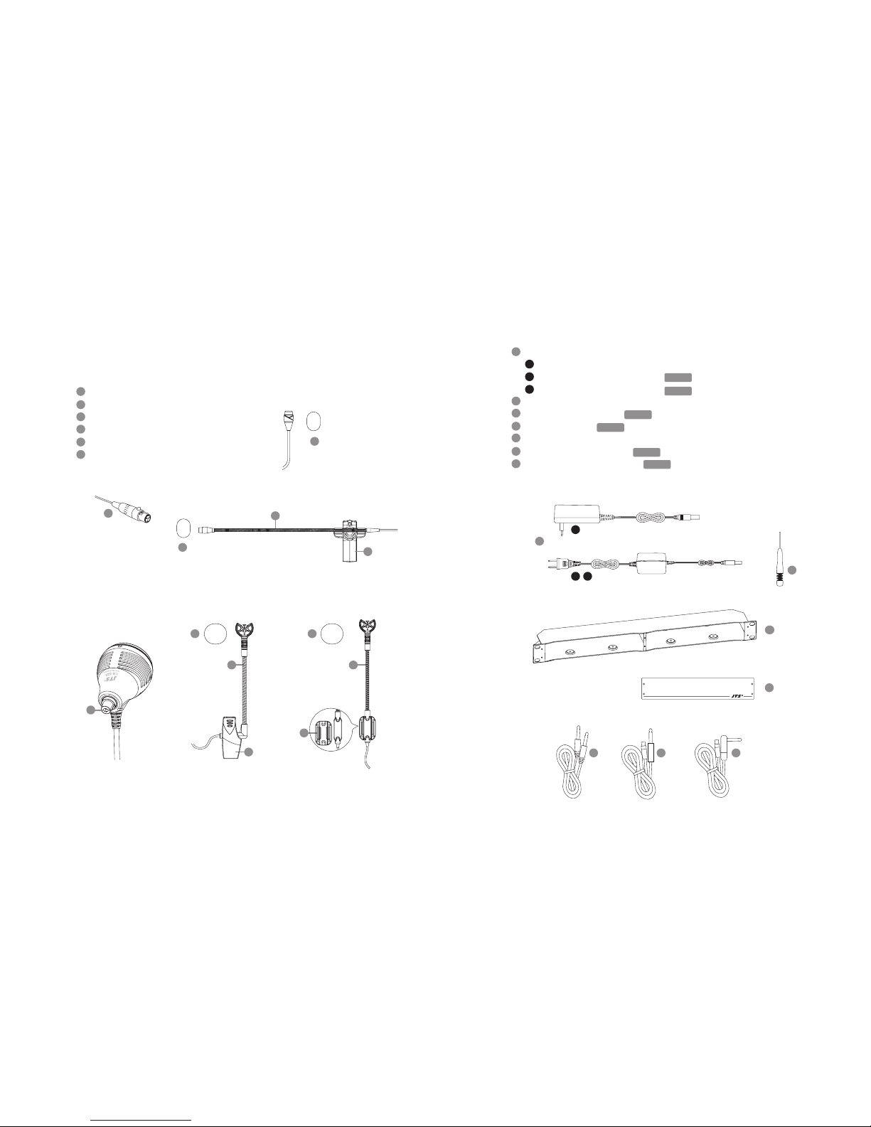
AC/DC adaptor
Switching Power Supply(100V~240V , 50~60Hz)
Linear Power Supply (220V , 50Hz)
Linear Power Supply (220V , 60Hz)
Screwdriver
DR-900 Dual Rack Adaptor
RP-900 Panel Cover
AF output cable (with Φ6.3 plug at both ends)
GC-80/GC-100 Guitar Cable
GC-80L/GC-100L Guitar Cable
4-5 Accessories
60
62
63
59
61
58
57
60
59
62 63 61
58
57
Option
Option
Option
Option
Option
Option
A
B
C
A
B C
56
Gooseneck
Clip
Bracket
Volume Control
Windscreen
4 Pin Mini XLR
54
55
56
53
52
55
55
51
CX-508WCX-520
CX-500F
CX-500
CX-516W
52
51
51
55 55
51
53
52
54
Page 10
WIRELESS MICROPHONE SYSTEM
15
16
5. Preparing Procedures & Basic Operation
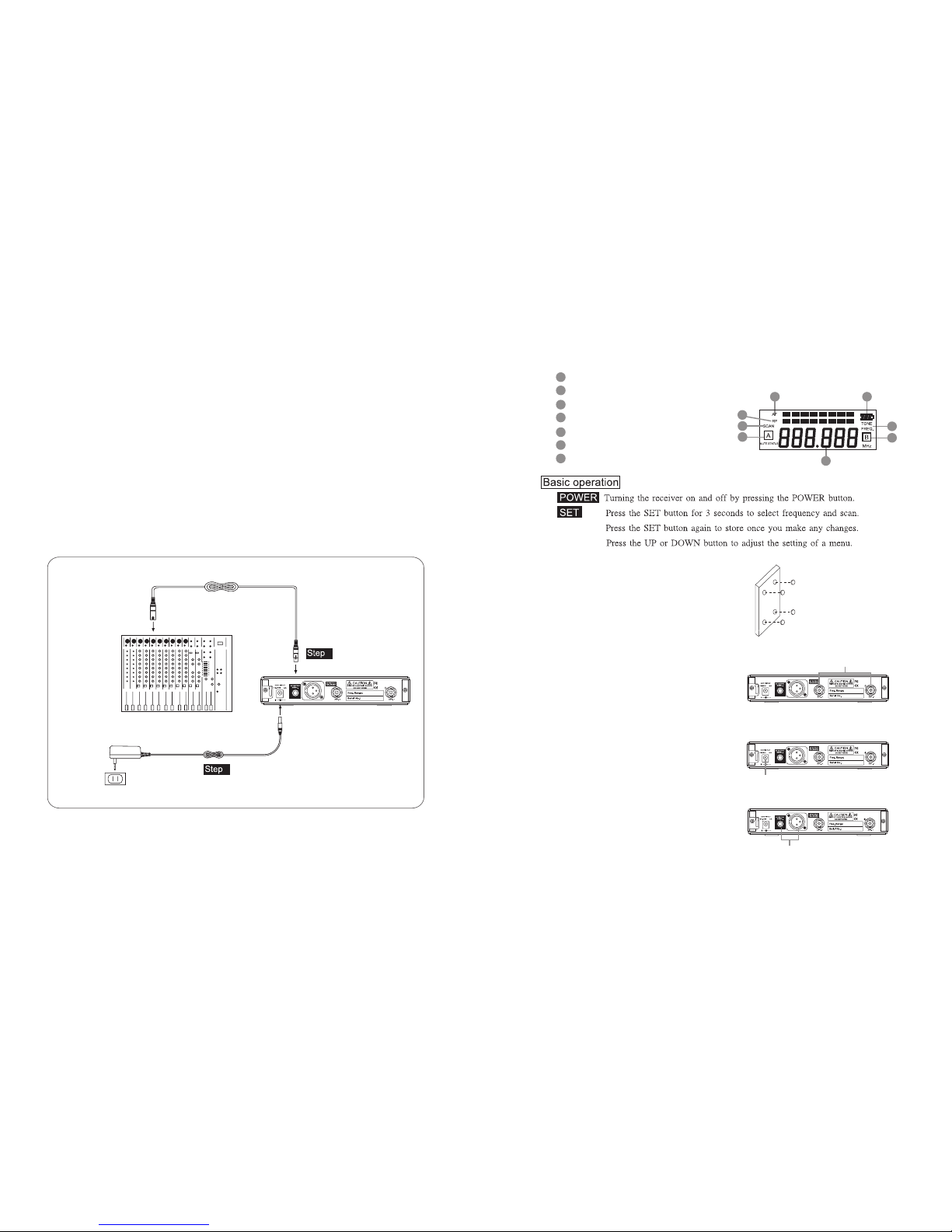
5-1 Receiver // US-901D US-9001D
(1) Power output connector
Plug in one end of AC/DC adaptor cable to DC input socket in the rear panel of receiver, and
plug another end into an AC outlet.(Step 1)
(2) Audio Output Connector
Connect one end of the AF output cable to the AF output socket in the rear panel, then plug
another end to the “MIC IN” input socket of a mixer or amplier.(Step 2)
Receiver equipped with balanced XLR output and Unbalanced φ6.3mm output, choose the
proper way for use.
MIXER
AC/DC ADAPTOR
AC POWER SOCKET
AUDIO OUTPUT
DC INPUT
2
1
250
1856
(3) LCD panel
AF signal
RF signal
Display for SCAN mode
Display for set FREQ. mode
Main display
Diversity display (A or B antenna)
Baery display for the transmier
(4) Seing the rubber pad
Four self-adhesive rubber pads are provided
to ensure the stability.
ey are to be placed on the boom side of
the receiver.
(5) Connecting the antennas
e user-friendly receiver antenna comes
with easy mount on socket for eortless
connection. Connect two antennas on the
back of the receiver and align them upward.
(6) Connecting the main unit
Plug in the DC connector on the back of the
receiver (DCV INPUT).
(7) Connecting the amplier/mixer console
Plug in the amplier/mixer console to the
(AF OUT UNBAL / BAL ) sockets.
66
68
65
67
70
64
69
65
66
69
67
69
68
7064
250
1856
250
1856
250
1856
ANT.1 / ANT.2
DCV INPUT
AF OUT UNBAL/BAL
Page 11
WIRELESS MICROPHONE SYSTEM
17
18
POWER
SET
MIN. MAX.
DIVERSITY RECEIVER
US-901D
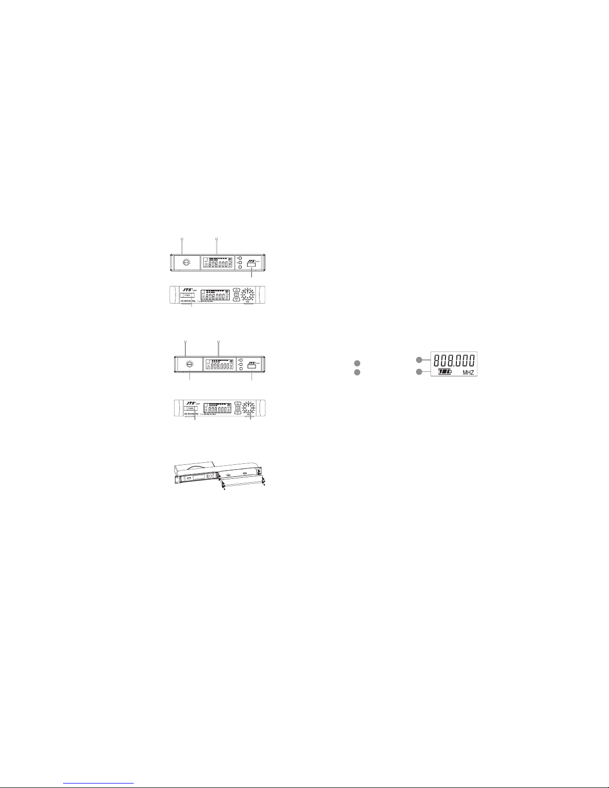
(8) Turning the receiver on/o
Turn the receiver on by pressing the
(POWER) buon.
(9) Adjusting the AF output level
Use the AF output level control located on
the front side of the receiver to adjushe AF
signal level that appears at output.
(10) Dual Rack Adaptor set
e dual rack adaptor is available to unify the
half rack space into a standard EIA size with
single or dual units.
AF OUTPUT LEVEL
POWER
POWER
AF OUTPUT LEVEL
POWER
SET
MIN. MAX.
DIVERSITY RECEIVER
US-901D
POWER
POWER
(1) Turning the transmier on/o
e on/o switch is located on the boom of the microphone.
(2) Inserting and changing the baery
1. Loosen the microphone head counter-clockwise. (Figure 1)
2. Hold on to both baery tray buons to release it. (Figure 2)
3. Insert 2 pieces of UM-3 1. 5 V baeries, remember to match
correct polarity. (step1 of Figure3)
4. Directly push the baery tray back. (step2 of Figure3)
5. Aim the connectors exactly for screwing on the microphone
head clockwise. (Figure 4)
(3) LCDpanel
Main display
Baery indicator
5-2 Handheld Transmitter // Mh-950 Mh-960
71
72
71
72
Page 12
WIRELESS MICROPHONE SYSTEM
19
20
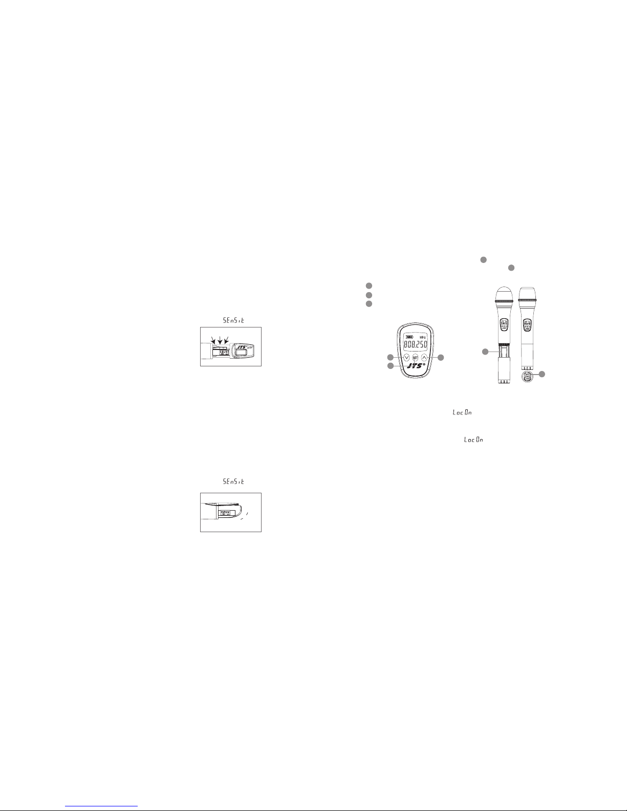
(4) Mh-950 Press the SET buon to select between frequency and sensitivity.
1. Frequency adjusting
Press the UP or DOWN buon to adjust the seing of a menu.
1-1 Hold SET buon for 3 seconds to activate frequency.
1-2 Once you see ”MHz” blanking , you are ready to select your desired frequency
by using UP and DOWN buons.
1-3 Press the SET buon again to store your changes.
2. Sensitivity adjusting
2-1 Press the SET buon twice to select sensitivity. Lasting for 3 seconds at the rst
press, then 1 second for the second press, and the display appears .
2-2 Use UP and DOWN buons to adjust changes.
2-3 Finally press EET buon again to store your changes.
(5) Mh-960 Press the SET buon to select between frequency and sensitivity.
1. Frequency adjusting
Press the UP or DOWN buon to adjust the seing of a menu.
1-1 Hold SET buon for 3 seconds to activate frequency.
1-2 Once you see ”MHz” blanking , you are ready to select your desired frequency
by using UP and DOWN buons.
1-3 Press the SET buon again to store your changes.
2. Sensitivity adjusting
2-1 Press the SET buon twice to select sensitivity. Lasting for 3 seconds at the rst
press, then 1 second for the second press, and the display appears .
2-2 Use UP and DOWN buons to adjust changes.
2 -3 Finally press SET buon again to store your changes.
UpSetDown
Up
Set
Down
(1) Insert 2 pcs 1.5V baeries into the baery tray.
(2) Aer puing into the baery, switch on the power on/o.
(3) LCD operation
Down buon
Up buon
SET buon
5-3 Handheld Transmitter // Mh-8900(i)
15
16
14
18
19
Mh-8900i
19
18
Mh-8900i
15
14
16
(4) Relieved Lock-on
Press “SET” buon three sec. till“ ” show up, then press “DOWN” buon plus “SET”
buon to store the lock-on relieved.
1. Press any buon the display shows“ ” during lock-on model. And it will not disappeared either electric o.
2. Mh-8990 Press the SET buon to select between frequency and
sensitivity.
2-1 Frequency adjusting
Press the UP or DOWN buon to adjust the seing of a menu.
1. Hold SET buon for 3 seconds to activate frequency.
2. Once you see “MHz” blanking, you are ready to select your desired frequency by
using UP and DOWN buons.
3. Press the SET buon again to store your changes.
Page 13
WIRELESS MICROPHONE SYSTEM
21
22
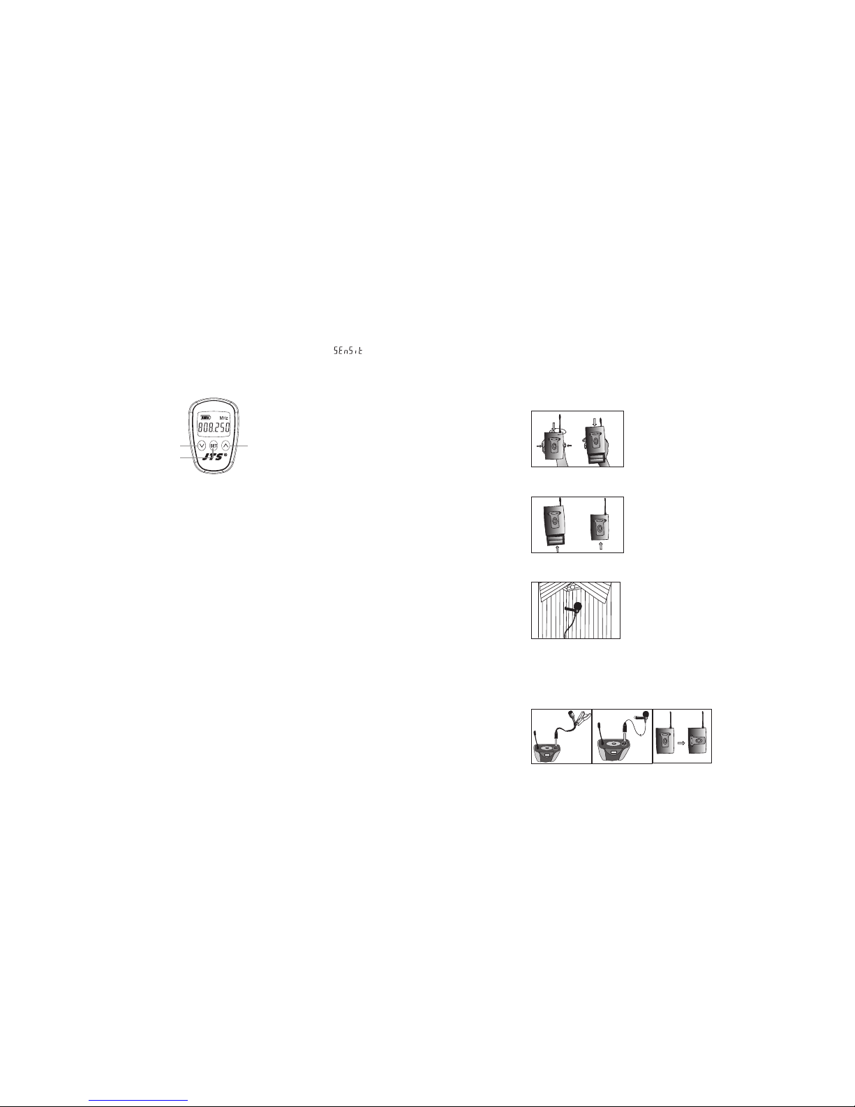
2-2 Sensitivity adjusting
1. Press the SET buon twice to select sensitivity. Lasting for 3 seconds at the rst
press, then 1 second for the second press, and the display appears“ ” .
2. Use UP and DOWN buons to adjust changes.
3. Finally press SET buon again to store your changes.
2-3 UP buon to activate “Lock mode”
Hold on to UP buon for 3 seconds to activate “Lock mode”, press again to unlock.
(Prevent accidental programming or switching o )
Mh-8900i
DOWN UP
SET
5-4 Body-pack Transmitter // PT-950B(mi)
(1) Turning the transmier on/o
e on/o switch is located on the top of the transmier.
(2) Inserting and changing the baery
1. e baery tray is located on the back of the transmier.
2. Hold on to both belt clip buons to release it.
3. Insert 2 pieces of UM-3 1.5V baeries. Remember to match correct polarity.
4. Directly slide the belt clip back.
(3) With Lavalier microphone
Aach Lavalier microphone to clothing, tie, lapel, where is the suitable place of sound
pick-up. Plug the mini XLR on the microphone cable into the “MIC. IN” on the body-pack
transmier.
Page 14
WIRELESS MICROPHONE SYSTEM
23
24
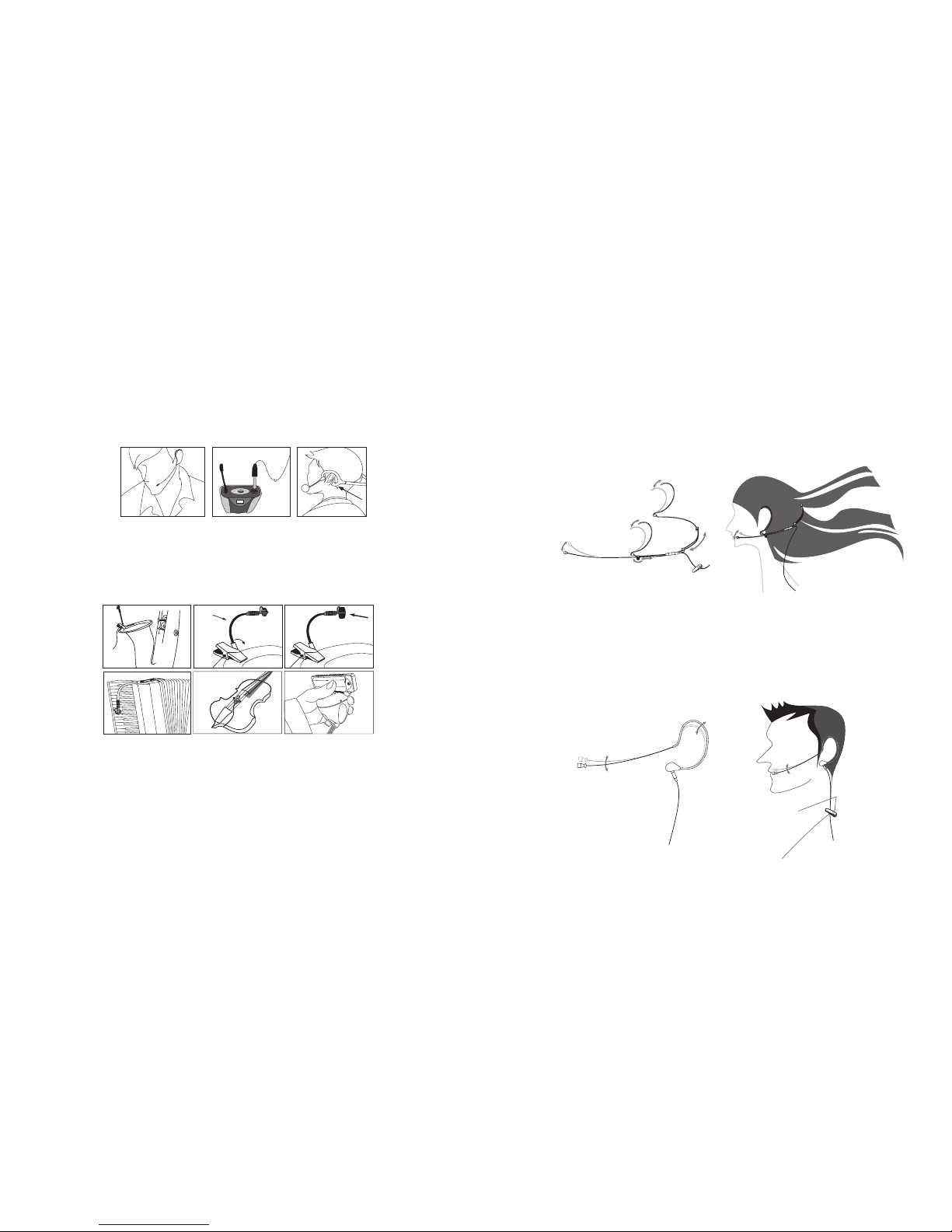
(4.) With Headset microphone
Put the neck-frame behind your neck meanwhile x the temples on your ears. Adjust the
gooseneck to aim the microphone toward the suitable sound source, which is about 1.5-2
inches distance from your mouth. Plug the mini XLR on the microphone cable into the
“MIC. IN” on the body-pack transmier.
(5) Instrument Microphones
e system is compatible with JTS various instrument microphones.
For detail please refer to user’s manuals of these microphones.
MIC IN
(6) Ear-hook Microphone
1. Lightweight Dual Ear Hook Microphone
Try on whether the headset is t.
Adjust the headband to a suitable width.
Tighten or loosen the curve of the ear-hook by twisting the loop or expanding it.
Curve and bend the boom to t your face.
Aach the detachable cable to a suitable place by a cable clip.
2. Lightweight Single Ear Hook Microphone
Try on whether the original cur ve is tight or loose.
Re-try and push the xed cur ve against your earlobe.
Curve and Bend the boom to t your face.
Aach the detachable cable to a suitable place by a cable clip.
Page 15
WIRELESS MICROPHONE SYSTEM
25
26
(7) Basic operation
1. Frequency adjusting
1-1 Hold SET buon for 3 seconds to activate frequency.
1-2 Once you see “MHz” blanking, you are ready to select your desired frequency by
using UP and DOWN buons.
1-3 Press the SET buon again to store your changes.
2. Sensitivity adjusting
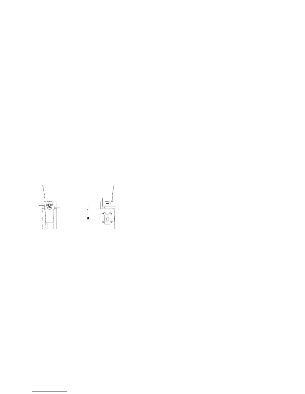
e sensitivity control(AF level control) is in the up-le of the transmier’s back. Please
use the adjusting sticker to adjust the proper level.
3. To activate “Lock mode”
Hold on to UP buon for 3 seconds to activate “Lock mode”, press again to unlock.(Prevent accidental programming or switching o)
ATTENUATION PAD
AF LEVEL CONTROL
AUDIO ADJUSTING STICKER
DOWN
UP
SET
6. Recommendation
(1) In order to achieve the optimum reception condition and also extend the operating distance,
please leave a “open space” between the receiver and transmier.
(2) Keep the devices away from the metal objects or any interference sources, at least 50 cm.
(3) To avoid the feed-back eect, don’t leave the mic. to aim at the speakers directly.
(4) For best pick-up paern, please hold the middle of the mic. body.
(5) Remove baeries from the baery compartment when the transmier will not be used for a
long time.
(6)When you need to replace the baeries, please replace both baeries at the same time with
new ones.
Page 16

WIRELESS MICROPHONE SYSTEM
27
7. Important Notice
(1) JTS oers wireless systems in a selection of bands that conform to the dierent government
regulations of specic nations or geographic regions. ese regulations help limit radio
frequency (RF) interference among dierent wireless devices and prevent interference with
local public communications channels, such as television and emergency broadcasts.
(2) For information on bands available in your area, consult your local dealer or phone JTS.
More information is also available at JTS’s website (www.jts.com.tw).
(3) is Radio apparatus may be capable of operating on some frequencies not authorized in
your region. Please contact your national authority to obtain information on authorized
frequencies and RF power levels for wireless microphone products.
 Loading...