

Page 1
JTL USER GUIDE TEMPERATURE MONITOR TYPES: TA210, TA211
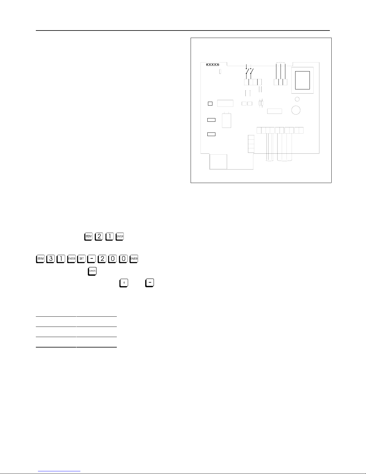
CON4
MAINTENANCE
E L N
CN4
CN5
CON1
1
2
3
4
4321
CN1 CN2 CN3
-
+
CON2
CON3
TEMPERATURE
SENSORS
ZONE
DEFROST
230V
DOC 02523 ISS 3
INPUT 2
WIRING
DI1
DI2
DI3
COM
TA200, DC200, CR200 MONITORS
Electrical Installation Requirements
Care should be taken to separate the power and signal cables to prevent
electrical interference and possible damage due to inadvertent
connection.
TA210
TA210 inputs are electrically (optically) isolated. A line voltage should be
connected for signal present. The terminal marked COM should be
connected to the supply voltage neutral.
NOTE: The line voltage MUST BE on the same phase as the unit supply.
TA211
The inputs are 5 V dc and are electrically (optically) isolated. The
+5 V signal should be connected for signal present. The terminal
marked COM should be connected to 0 V.
CE Conformance
This unit conforms with the relevant EU standards when installed
according to the JTL Installation Requirements for this product.
Inputs and Temperatures
Inputs (connector CN4/5) Temperatures (connector CN1-3)
DI1 Defrost AI1 Air on temperature (T1)
DI2 Input 2 alarm AI2 Air off temperature (T2)
DI3 Not used AI3 Not used
COM Supply Neutral
Use of Maintenance Unit
The monitor can be checked and the operation adjusted using a JTL
portable maintenance unit which plugs into the monitor. Each item of
information has an item number. The more important items are listed
in the tables overleaf. Examples:
To read item 21 press:
To set item 31 to -20.0 press:
To correct errors press:
To select next or previous items press: and
JTL Network Communications
The JTL network port (connectors 2&3) is 2 wire (half duplex)
communications. The wiring of the port is:
2 wire
1-
2+
3 Not used
4 Not used
Note all network products must be connected in parallel without cross
connections. The Rx connections must be connected to the Tx
connections at the network controller.
The communications rate is automatically selected for 4800 baud.
Initial Commissioning
The monitor has a set of data built in to its program for use during
commissioning. This can be accessed setting item 9 to 1. This loads into
the monitor a standard set of data. Adjustments should then be made
as necessary. The range over which the settings can be adjusted shown
overleaf.
The unit number for the JTL communications network should be set on
item 1.
Defrost
The defrost sequence can be initiated via the Jnet network (with defrost
scheduler) or by a contact input. Item 107 must be set accordingly.
Defrost is terminated when either the network command or contact
input is taken away. An adjustable maximum defrost period is set on
item 57. An alarm is generated if a defrost exceeds this time and is only
cleared after the defrost has finished.
Defrost Recovery
When the defrost is ended the monitor enters defrost recovery for a
period set on item 64.
Alarms
The reported temperature is monitored continually. The reported
temperature is computed from the T1 and T2 temperatures. A factor is
used to proportion the T1 and T2 temperatures. If a single sensor is
used then a value can be added to offset the reported temperature
using item 34.
In two sensor mode, the reported temperature is averaged over a period
set on item 47. If the average temperature exceeds the alarm level,
then an alarm is transmitted on the JTL alarm system.
In single sensor mode (T1 only) an alarm is transmitted on the JTL alarm
system if the reported temperature exceeds the alarm level for a period
longer than the delay set on item 47.
Temperature alarms are cancelled during defrost and defrost recovery.
Input 2 Alarm
A general purpose alarm facility is provided when a mains alarm signal
(eg. Plant fault, door open) is given to the monitor, an alarm is available
after an adjustable delay on the JTL Network. The delay is set on item
36.
In the default condition (input not inverted, Item 66=0), the line voltage
should be present to indicate; plant healthy (Item 98=2,4,5), door closed
(Item 98=3), unit shutdown (Item 98=6). When a unit is shutdown, all
temperature and defrost alarms are cancelled, sensor faults are still
reported.
Page 2
Doc No. 02525 TA210-TA211.wpd Issue 6.1 March 2006
www.jtl.co.uk
JTL Systems Ltd . 41 Kingfisher Court . Hambridge Road . Newbury . Berks . RG14 5SJ Tel: (01635) 263646 Fax: (01635) 263647
JTL SERVICE CENTRE HELP DESK: 0870 321 HELP (4357)
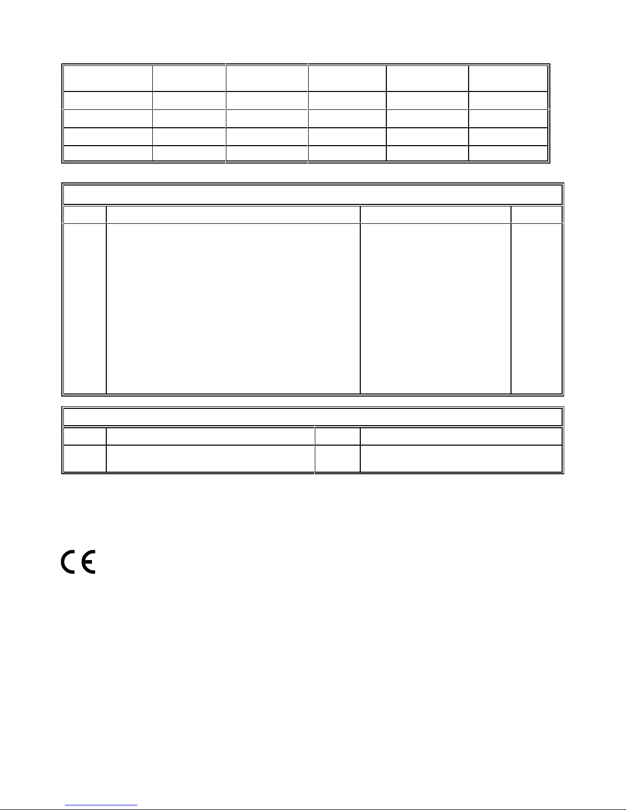
According to the application the unit should be set up as follows:
Cabinets
(Item 98=2)
Coldrooms
(Item 98=3)
Air Handlers
(Item 98=4)
Cabinets (TA211)
(Item 98=5)
Cabinets
(Item 98=6)
Input 2 Function Plant fault alarm Door open alarm Plant fault alarm Plant fault alarm Unit shutdown
T1 Air on Air on Air on Air on Air on
T2 Air off Air off Air off Air off Air off
Temperature ratio 0 - 100% 100% 0% 0 - 100% 0 - 100%
ADJUSTABLE PARAMETERS
Item Function Range Units
1
30
31
32
33
34
36
38
47
57
65
66
67
102
107
64
98
JTL network unit number
Setpoint (for optimiser compatibility, does not affect alarm logic)
Low temperature alarm level
High temperature level
Cabinet temperature factor
Single sensor temperature offset
Plant alarm delay time
Sensor selections
Alarm delay time/Period over which averages taken
Maximum defrost time
Invert defrost input
Invert plant alarm input
Door alarm critical
Sensor type selection
Defrost strategy selection
Delay after defrost
Unit sub-type
0.1 to 899.9
-99.9 to +99.9
-99.9 to +99.9
-99.9 to +99.9
0 to 100
-10.0 to + 10.0
0 to 99
0=none 1=T1 2=T1 & T2 3=T2
0 to 99
5 - 60
0=no 1=yes
0=no 1=yes
0=no 1=yes
0=Standard sensor 1=Hot sensor
0=none 1=contact 2=network
0 to 60
2=DC 3=CR 4=AH 5=DC(TA211) 6=DC
°C
°C
°C
%
°C
mins
mins
mins
mins
OTHER USEFUL ITEMS
Item Function Item Function
20
21
Reported temperature
Air on temperature (T1)
22
70
Air off temperature (T2)
Operating mode
Full operating manuals and item number information can be obtained from your supplier or JTL Systems.
Supply and Input Requirements
230 V ac 48-62 Hz
Supply 2 VA maximum
Inputs 2 mA maximum
This unit conforms with the relevant EU standards when fitted in accordance with its installation instructions.
 Loading...