

Page 1
Installation, Programming and Operator Guide
Part Number 320115B1
Premises Pager System
2600 Desktop Transmitter
2601 Desktop With Telephone Connect
®
Page 2
Introduction:
Congratulations on your purchase of the Premises Pager Model 2600 or 2601
System. Please take a few minutes to review this manual prior to installing and
operating your system.
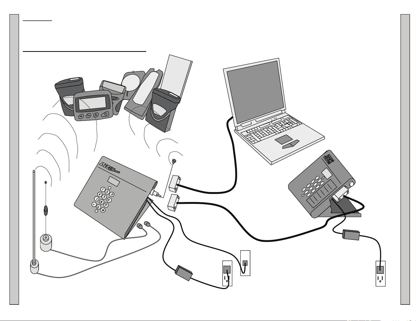
2600 & 2601 Series System Components:
Pagers
Desktop
Transmitter
Please inspect the System upon receipt. If the contents appear to be damaged,
notify the shipper immediately to file a claim and notify JTECH Customer Care. If
components are missing, contact JTECH Customer Care.
If you have any questions or need assistance, please call JTECH Customer Care
at 800-321-6221 or 561-997-0772, option 6.
Computer With
RS232 Port
(User Supplied)
Use with RS232
Transmitter Option
Null Modem
Adapter
Remote Keypad
(Optional Equipment used
with RS232 Transmitter
Option)
Magnetic Mount
Antenna
(Optional Equipment)
Model 2600 & 2601 Series System Components Introduction
Telephone (Analog) Line
If Required for Telephone
Connect Transmitter Option
6Ft Antenna
(Optional Equipment)
2
120VAC
Electrical
Outlet
2 3
120VAC
Electrical
Outlet
(If Required)
Model 2600 &2601 Series System Components Introduction
Page 3
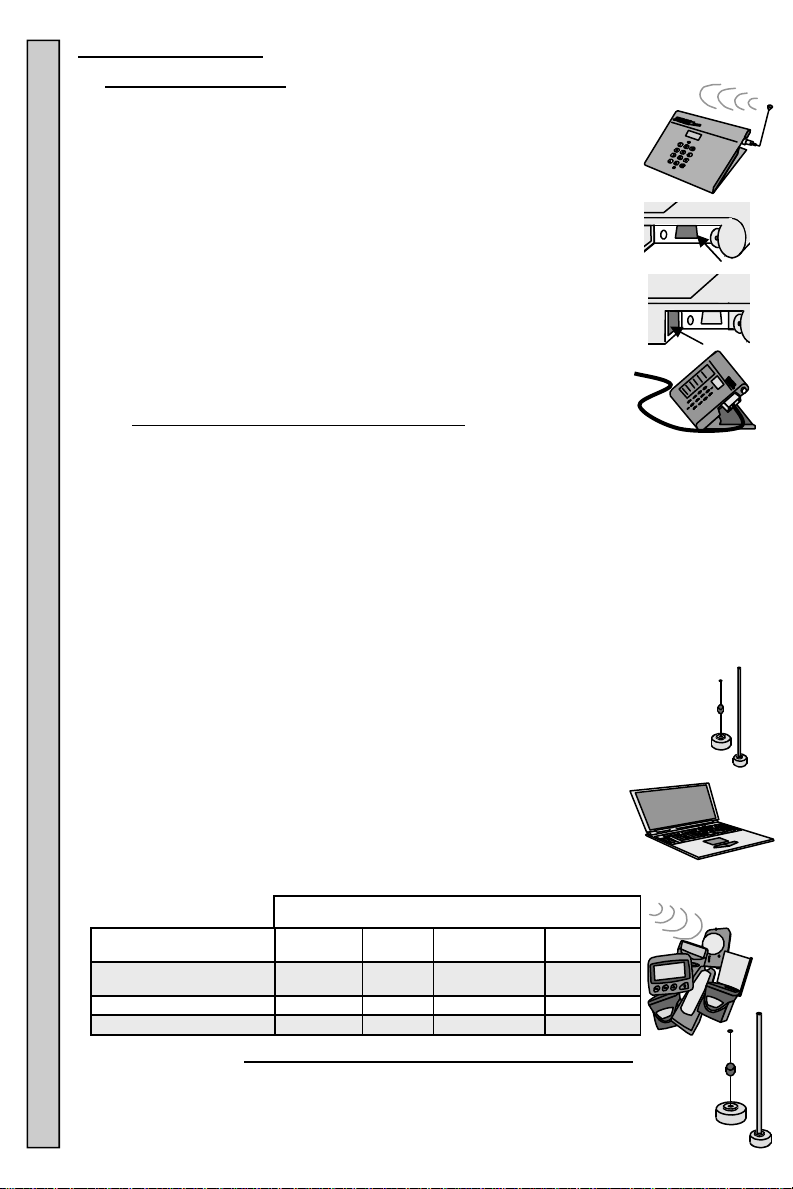
System Components:
Desktop Transmitter:
Pages Vibe, Tone, Flash, Numeric and Alphanumeric Pagers.
Sends numeric pages to Numeric and Alphanumeric Pagers.
RS232 (If Connected to a users Computer):
Pages Vibe, Tone, Flash, Numeric and Alphanumeric Pagers.
Sends numeric pages to Numeric and Alphanumeric Pagers.
Sends alphanumeric pages to Alphanumeric Pagers.
User software and interface development is required.
Phone Connect (Model 2601 Only):
Pages Vibe, Tone, Flash, Numeric and Alphanumeric Pagers.
Sends numeric pages to Numeric and Alphanumeric Pagers.
Remote Keypad and Cable (Optional):
Attaches to the Transmitter to page remotely, up to 50ft
away from the Transmitter.
2600 - 2601 Transmitter Specifications:
Display: 2 Line x 8 Character Alphanumeric LCD
Operating Voltage: 13.5VDC 2.4A 120VAC power adapter
Power Output: 0.1-2 Watts - adjustable using 5 levels.
Channel Spacing/Deviation: 12.5KHz / ±4.25KHz
Modulation/Protocol: FSK 512 BPS
Transmit: 512 Baud
RS232 Communications: 1200 Baud
Antenna Port/Type: 50 ohm BNC / Rotating whip (standard)
Operating Frequency: UHF synthesized 450-470 MHz. (standard)
Temperature Stability: -22°to 122°F (-30 to 50°C) at better than 5 ppm
Size 8”x7.13"x1.31"(203mm x 181mm x 233mm)
Weight 3.2 Lbs (1.45Kg)
Certifications: FCC Part 15. IC
Range:
Maximum Transmitter range is 1½-2 miles (2.4-3.2Km).
Range will vary, depending on each location’s environment.
Increase maximum Transmitter range with an optional remote
Magnetic Mount Antenna, 6ft Antenna or Extended Range Kit (FCC
license required).
Computer (For use with RS232 and is user supplied):
Computer must have a RS232 port with 1200 baud ability.
Program using Visual Basic, etc. to control Pagers.
Pagers: The table shows the type of information that can be sent and which Pagers
can receive it.
Type of Page Information
Vibe, Tone and Flash
(Guest Pager)
Numeric X X X X
Alphanumeric X
Keypad RS232
X X X X
Optional Antenna: Requires FCC approval and licensing for use.
Magnetic Mount Antenna with 12ft Cable: Is a indoor use only Antenna,
which has a magnetized base for mounting to steel or iron.
6ft Antenna and 25ft Cable: Is a indoor/outdoor use Antenna that can be
Antenna Pagers Computer Range Specifications System Components
mounted to any stable surface.
4
Sent By
Remote Keypad
Phone
Connect
Page 4
Extended Range Antenna Assembly: Is a indoor/door use Antenna and a 35 Watt
Power Amplifier, Power Supply and 50 or 100ft Cable. It increases the output of
the Transmitter to 35 watts maximum and range of up to 5 miles.
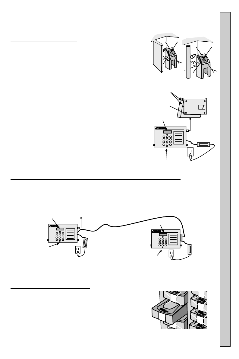
Installing the Transmitter:
The Transmitter can be surface mounted, used on a
on a counter or desk top or wall mounted.
The best location is in clear view of the paging area.
Walls, pipes, ducts, mirrored glass, etc. may weaken
or misdirect signals.
Locate the Transmitter away from liquids and extreme heat.
1. To secured the Transmitter to a counter or wall:
A. Remove the 2 screws from each side of the
housing and 4 rubber feet in the base plate.
B. Secure the base plate as needed. Mounting
hardware is user supplied.
C. Attach the housing to the base plate.
2. Change the angle of the Transmitter by adjusting
the position of the base.
3. Con nect the Antenna and point upward (vertical).
4. Plug in the AC Power Cord into the Adapter.
5. Plug the Adapter into the Transmitter.
6. Plug the AC Power Cord into a 120VAC outlet.
7. When powered and ready, the Transmitter display
will show “Enter Pager #” and the PWR Light will be ON.
Remote Keypad Connection And Operation (Optional Equipment):
1. Attach one end of the 25ft RS232 Cable to the Transmitter and the other to the
Null Modem Adapter on the Remote Keypad.
2. Plug the Adapter into the Remote Keypad.
3. Plug the Adapter into the Transmitter.
4. Connect all cables and the Antenna before applying power to the Transmitter
and Remote Keypad.
Display
Transmitter
PWR
Power Light
Antenna
Power Adapter
AC Power
Cord
Remote
Keypad
PWR Power Light
5. When powered and ready, the displays will show “Enter
Pager #” and the PWR lights will be ON.
Paging Using Rechargeable Guest
(Vibe, Tone and Flash Pagers):
1. Remov e the Pager you wish to page from the
Charging Rack.
2. Enter the number of the Pager you wish to page on
the Transmitter or Remote Keypad.
3. Press # to send the page.
4. The XMIT light on the Transmitter will turn ON,
confirming the page is being sent. If using a Remote
Keypad, the Keypad XMIT light does not ON.
Screws
Rubber
Feet
Display
PWR
Power Light
Display
6
AC Power Cord
Null
Modem
Adapte
AC Power Cord
5
7
Antenna
Adapter
Power
Adapter
1
4
5
1
5
1
6
See “Enter Pager #” Menu Functions for more information.
Paging Using Guest Pagers Remote Keypad Installing The Transmitter Antenna
5
Page 5
Range Testing the Transmitter
1. Once installed and powered, the Transmitter will display “Enter Pager #”.
2. The red (PWR) light at the bottom of the Transmitter keypad will be ON.
3. Enter 9990# on the keypad.
4. T he Transmitter sends a page every 5-6 seconds to all Pagers placed in
Group 99 or Pager number 1 (factory defaults). See Dynamic Group for
additional information. Use Guest Pagers only, Wait Staff Pagers cannot be
used for range testing this Transmitter.
5. Pagers need to be fully charged or have fresh batteries installed.
6. Slowly walk the surrounding area with the Pager.
7. Check that the Pager continues to alert with a tone.
8. Cha nging the Transmitter location or moving surrounding objects may effect
range results.
9. If the Pager no longer alerts, walk back slowly
toward the Transmitter until the Pager’s alert
begins again. Mark this spot as the maximum
range of the Transmitter in this direction and
continue to check the remaining area.
10. Press any button on the keypad to end the
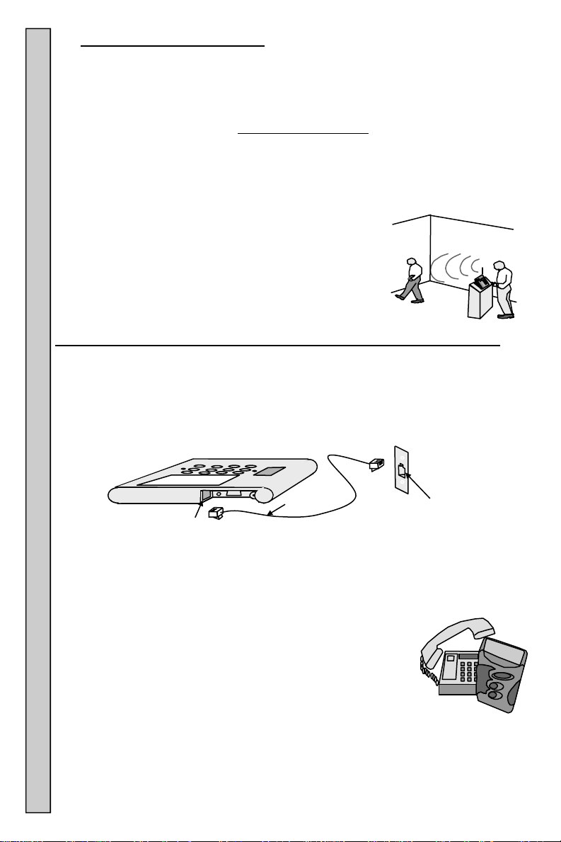
2601 Transmitter Phone System Connection And Operation (If Required):
range test.
Installation: Requires a dedicated analog telephone line which can “hear” the
tones from a push button telephone.
1. Connect the phone cord to the jack on the side of the Transmitter.
2. Plug the other end into an jack wired to a dedicated telephone (fax)
line.
3. If ‘continuous’ DTMF tone is available, change Transmitter settings:
6
Phone Cord
Transmitter Jack
A. For ‘continuous’ DTMF enter * # 577.
B. For ‘short burst’ DTMF enter * # 576 (factory default).
Ignore the display screen during this procedure.
Paging a Numeric Pager using the telephone:
1. Pick up the phone and listen for the dial tone.
2. Dial the phone number that has been assigned to the
Transmitter.
3. Listen for a beep from the telephone that confirms the
Transmitter is ready.
4. Within 8-10 seconds, use the telephone keypad:
a. Enter the Pager number (up to 4 digits).
b. Press the * key.
c. Enter a numeric message, if desired (16 digits maximum).
d. Press the # key to send the page.
5. A beep will be heard on the phone confirms the message was sent.
6. Hang up the telephone.
Paging Using The Telephone Range Testing
Telephone
(Fax) Jack
Page 6
Group Paging using the telephone: Group information can be preprogrammed
into the Pagers at your Distributor’s site or JTECH. “Dynamic” Groups
can be programmed by the user. See “Add a Pager to a
Dynamic Group” on page 14 for more information.
1. Pick up the telephone and listen for the dial tone.
2. Dial the telephone number that has been assigned to
the Transmitter.
3. Listen for a beep that confirms the Transmitter is ready.
4. Within 8-10 seconds, use the telephone keypad:
a. Press the * key.
b. Enter the Group number (1-99) to page. Also see “Dynamic Group ”
programming for more information.
c. Press the * key.
d. Enter a numeric message, if desired (16 digits maximum).
e. Press the # key to send the page.
5. A beep heard on the phone verifies that the message was sent.
6. Hang up the telephone.
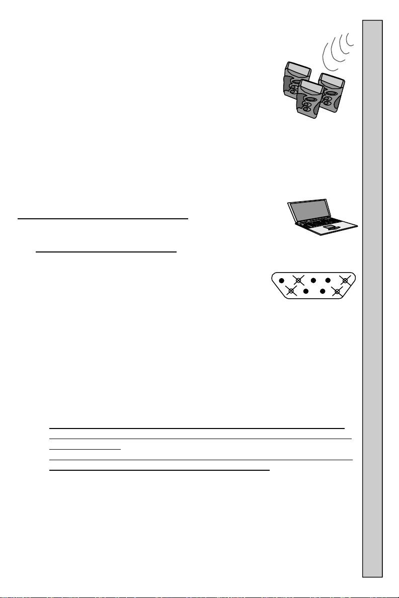
Programming For The RS232 Interface: To communicate with
the Transmitter, the computer software must send RS232 1200
baud message information using the following protocol.
RS232 DB9 Pin Identification:
Pin 2 = Transmit Data from Transmitter to Host (Attached to Line
Driver Transmit Side).
Pin 3 = Receive Data from Host to Transmitter (Attached to Line
Driver Receive Side).
Pin 5 = Signal Ground.
Pin 7 = Request to Send Line from Host to Transmitter (Attached to
Line Driver Receive Side).
Pin 8 = Clear to Send Line from Transmitter to Host (Attached to Line Driver Transmit
Side) .
Pins 1, 4,6 and 9 are not used.
8 9
RS232 Baud Rate And Settings
1200,N,8,1 (1200 Baud, No Parity, 8 Data Bits, 1 Stop Bit).
RS232 Handshaking-Request To Send (RTS) - Clear To Send (CTS)
The Transmitter uses CTS to allow data out of the Host output buffer.
The Transmitter does not monitor RTS.
The Transmitter requires the host to stop sending data immediately, when
CTS signal switches from high to low. Incoming data is not monitored while
CTS signal is low.
High-speed serial port drivers may continue to send data after CTS signal is
switched to low. This condition causes data to be lost. Serial port drivers
having settings for the amount of buffered data ,should be set to 0.
7 Digit Message Format: Contains six parts:
1. Preamble (3 bytes) 4. Separator (1 byte)
2. Function Bit (1 byte) 5. Pager Message (120 bytes max)
3. Cap Code (7 bytes) 6. Terminator (1 byte)
Preamble: Is a 3 character hex string that supplies start up synchronization
“padding” between messages IN, an output buffer, and information to the
Transmitter , that a message is coming. The Preamble is [Chr$(255)].
1 2 3 4 5
6 7
RS 232 Programming Group Paging
7
Page 7

Function Bit: The Function Bit is the single hex character following the preamble.
This character tells the Transmitter which bit to turn ON in the POCSAG
message sent. Characters are:
(Hex 01) Non Priority Alert for Numeric Pagers.
(Hex 02) Priority Alert for Numeric Pagers.
(Hex 03) Non Priority Alert for Alphanumeric Pagers.
(Hex 04) Priority Alert for Alphanumeric Pagers.
Cap Code: Cap Code is a seven digit data string which contains the address
information of the Pager to be used.
Cap Code Prefix: Is the first 3 digits of the Cap Code. ONLY Cap Code Prefixes
of 000 and 008-199 are allowed. If the first 3 digits of the Pagers cap code are
[000], the Transmitter will convert the last 4 digits (Pager number) of Cap Code
by multiplying by 8.
Example: Cap code information sent to the Transmitter = [0000111].
The Transmitter sends to the Pager address [0000888].
If the first 3 digits of the Pagers cap code are not
[000], the Transmitter will
send the Cap Code information as sent.
Example: Cap code information sent to the Transmitter = [1230111].
The Transmitter sends to the Pager address [1230111].
Separator: A separator is used between the Cap Code and the message sent . It
supplies information as shown in the table.
Messages:
Alphanumeric Pagers can be sent a maximum of 120 alpha characters
(using separator Chr$(02) orChr$(0A)).
RF Baud
Rate
512 Inverted Alpha Chr$(02) 02
512 Inverted Numeric Only Chr$(11) 0B
512 Non Inverted Alpha Chr$(10) 0A
512 Non Inverted Numeric Only Chr$(03) 03
Inverted Or
NonInverted
Alphanumeric Or
Numeric Only
Separator
In VB
RS232 Programming
Numeric Pagers can be sent a maximum of 16 numeric characters (using
separator Chr$(0B) or Chr$(03)).
Glowster and C ommPass use message characters as controls.
Example: To send default alert three to a Glowster or CommPass,
send the hex string to the Transmitter: FF FF FF 01 3P 3P 3P 3P 3P
3P 3P 03 0D] where PPPPPPP is the 7 digit Pager number. See Cap
Code for more information.
Example: To send a alert, other than the default, send the hex string
to the Transmitter [FF FF FF 01 3P 3P 3P 3P 3P 3P 3P 03 3A 3A 0D]
where PPPPPPP is the 7 digit Pager number and AA is the alert.
Alerts AA 3A,3A Alert type
The first ‘33’ in the message is used as a filler and can be any ASCII
8
31 33, 31 Alert 1 – one alert of 15 seconds total.
32 33, 32 Alert 2 – two alerts for 30 seconds total.
33 33, 33 Alert 3 – three alerts for 45 seconds total.
34 33, 34 Alert 4 – four alerts for 60 seconds total.
35 33, 35 Alert 5 – sixty alerts for 15 minutes total.
36 33, 36 Alert 6 - Demo alert 1 for 5 seconds total.
37 33, 37 Alert 7 - Demo Alert 2 for 7 seconds total.
38 33, 38 Alert 8 - Range Test Alert.
39 33, 39 Alert 9
30 33, 30 Alert 0 - Group Alert.
numeric digit.
Separator
In Hex
Page 8

Terminator: The terminator marks the end of message. The terminator character is
the Chr$(13) or Hex 0D.
Example Of Visual Basic Code: Below is an sample section from a Visual Basic
program. This example produces a non-inverted, non-priority page sent to a 512
baud Alphanumeric Pager.
MSComm1.PortOpen = True (Opens serial port for communication)
Preamble = Chr$(255) & Chr$(255) & Chr$(255)
FBit = Chr$(03) (Set Function bit #3 (non-priority for Alpha))
Cap Code = “1236789” (where ‘123’ is the cap code prefix and ‘6789’ is the Pager number)
Separator = Chr$(10) (This is an Non Inverted, 512 RF baud, Alpha Page)
PagerMessage = “This is a test Page”
Terminator = Chr$(13)
OutPutString = Preamble & Fbit & CapCode & Separator & PagerMessage & Terminator
MSComm1.Output = OutPutString
Example of Hex Data Stream Into Transmitter:
[FF FF FF 03 31 32 33 36 37 38 39 0A 54 48 49 53 20 49 53 20 41 20 54 45 53 54 20 50 41 47 45 OD]
Example Data Stream reads as:
| P | F | Cap Code:1236789 | S| Message: THIS IS A TEST PAGE | T |
P =Preamble
F = Function Bit
Cap Code = Seven Digits (the 3-digit cap code prefix should match the cap code prefix stored in the
Transmitter; the remaining 4 digits represent the Pager number)
S = Separator
Message = A maximum of 120 alphanumeric or 16 numeric characters (Function Bit determines
alphanumeric or numeric)
T = Terminator
Service
Assistance: For assistance, please contact JTECH Customer Care at
800-321-6221, fax at 561-995-2260 or email at wecare@jtech.com .
JTECH provides complete diagnostic technical support 24 hours a day, 7 days a
week.
Warranty: Equipment under warranty will be repaired without
charge.
Extended warranties are available. If the equipment is out of
warranty there will be a nominal service fee charged when the equipment has
been repaired and shipped.
Billing for Repairs: Terms are C.O.D. (company check), company billing or
credit card. If “advanced replacement” is required, replacement equipment will
arrive with a packing list and a Return Material Authorization Sheet (RMA). To
return the defective equipment and ensure proper credit, include the Return
Material Authorization (RMA) sheet in the shipment back to JTECH. Mark the
outside of the box with the Return Material Authorization (RMA) number. If
advance replacement of equipment service is used and the defective equipment
is not received back at JTECH within 10 days, JTECH will bill the amount of the
list price of the equipment to the Customer.
Shipping Costs: Costs to ship equipment from JTECH to the Customer paid by
JTECH. If Expedited shipping is needed, the Customer pays the additional
costs. Costs for shipping equipment from the Customer to JTECH are the
responsibility of the Customer. JTECH recommends using a shipping service
that is traceable in case shipping delays occur.
Service RS232 Programming
9
Page 9

Transmitter Settings And Functions
Settings and functions are programmable by entering information into the
Transmitter.
From the Transmitter keypad, press the * key to scroll down through the options.
Press # to select a displayed function.
Press 0 to move up through functions.
If information, other than what is required is entered, the display will show
‘Invalid’ and then return to ‘Enter Pager #. display’
To exit the settings and functions menu, enter ** on the keypad.
Password
To protect system settings, most menu selections are password protected.
The factory default password is “1234.” Password can be changed if desired.
Display Screen Enter Pager #
“Enter Pager #” is the ‘Home Position’ of the Transmitter display.
See Password and Change Password? for more information.
Detailed Menu information: Instructions on how to read the menus is as follows:
Information shaded is what will appear on the Transmitter display.
Follow arrows to the next step
BOLD Italics is information that needs to be entered on the Keypad.
Enter Pager #
Enter
Pager #
Enter NNNN #
Num NNNN
Snd ZZZZ
Enter
Pager #
Enter NNN*MMMMMMM#
Num NNNN
Snd ZZZZ
“Home” position of the transmitter.
Vibe/Tone/Flash Pagers
Enter the Pager number and #.
Numeric Pagers
Enter Pager number, *, optional 16 digit numeric message
and #. If ZZZZ is displayed, shown as 123 in the example.
Ex. Num 2
Snd 123
Pager number 2 has been entered in the keyboard, however Pager 123 is being paged. Pager 2 has been replaced with Pager 123. See Replace Pager? For more
information.
To cancel a page before it was sent Enter **.
NNNN =Pager Number
ZZZZ = Replaced Pager
MMMMMMM = Message
Enter Grp #
Enter
Enter Group # Enter Pager # Menu Display Password Settings
10
Pager #
Enter *
Enter
Grp #
Enter GG
Grp # GG
Snd
Pages a Group of Pagers (if programmed).
See Group for more information.
GG = Group Number
Page 10

Password
Enter
Turn Off Pagers?
Enter
Pager #
Enter **
Password
PPPP
Pager #
Enter **1234
Turn off
Pagers?
Enter #
#SendNow
n=HoursB
Enter B
#SendNow
n=HoursB
Enter the Password to access menu options.
See Password for more information.
Password (factory default) is 1234.
PPPP = Password
Turns OFF all Pagers not charging in charger racks.
Works with:
InstallCall Vibe/Tone Pagers.
Transmitter sends a “Over the Air” signal which turns the
Pagers OFF.
#SendNow
n=HoursA
Entering 0-9 while the display shows will change the delay
of the Transmitter. The delay is measured from the last
page sent from the Transmitter.
Factory default is set a 0 hours and the Transmitter will
send the Pager OFF command immediate.
Entering 1-9 at this screen will delay the Pager turn OFF
signal from 1-9 hours.
Turn Pagers back on individually using the Pagers ON
button.
B=hours of inactivity
Search Mode Enter
Enter
Pager #
Enter **1234*#
Search..
…...ing
Pager #
Enter 9999#
Search..
.….ing
Sends a repeating page to Pagers.
Works with:
Glowster Pagers.
CommPass Pagers.
PatronPass Pagers.
ParentPass Pagers.
PeoplePass Pagers.
Transmitter will send a page to all Pagers within range.
Pagers charging in the Charging Rack will not respond.
Allows user to find misplaced Pagers.
Press * to cancel Search Mode.
Search Mode Turn Pagers Off Password
11
Page 11

Send All Call Enter
Pager #
Enter ***1234**#
Sending
All Call
Num
Snd
Send All Call
Enter
Pager #
Enter 9998#
Sending
All Call
Num
Snd
Sends a page to all Pager at the same time.
Works with:
InstaCall Vibe/Tone Pagers.
Glowster Pagers.
CommPass Pagers.
PatronPass Pagers.
ParentPass Pagers.
PeoplePass Pagers.
Command can also be found in the menu functions.
Default # of Vibes?
Enter
Out Of Range (ON)
Enter
Out Of Range (OFF)
Out Of Range Default Vibes Send All Call
12
Pager #
Enter ***1234***#
#Alerts=
(1-5)? A
Enter A
#Alerts=
(1-5) A
Pager #
Enter ***1234****#
Out Of
Rng On?
Enter #
Enter
Pager #
Enter ***1234****#
Out Of
Rng Off?
Enter #
Adjusts the number of alerts the Pager produces.
Works with:
Glowster Pagers.
CommPass Pagers.
PatronPass Pagers.
ParentPass Pagers.
PeoplePass Pagers.
Allows user to change set the number of alerts from 1 to 5
(factory default is 3).
See Multi Vibe Page 16 for additional information.
A = Programmed # of Vibes 1-5
Turns ON/OFF the Out of range function of the transmitter.
Works with:
Glowster Pagers. PatronPass Pagers.
CommPass Pagers. ParentPass Pagers.
When Out Of Range is ON, the Transmitter sends a signal
every 10 seconds.
If Out Of Range is ON, any Pager moved outside the
Transmitter paging range will respond with a Out Of Range
Tone or Voice message if available).
When the Pager is brought back within Transmitter range
the Out Of Range Tone or Voice message (if available) will
stop.
See Range Testing to identify maximum Transmitter range.
Command can also be found in the menu functions.
Also use 9996# to turn Out Of Range ON.
Also use 9997# to turn Out Of Range OFF.
Page 12

Replace Pager
Enter Original Pager NNNN#
Enter New Pager ZZZZ#
Enter
Pager #
Enter **1234*****#
Enter Selection 1-4 S#
Old Pagr
# _ _ _ _
New Pagr
# _ _ _ _
1=POC Vb
2=Glwstr
Enter #
3=Numeric
4=Alpha
NNNNNow
ZZZZ TTT
Changes Pager numbers.
The new Pager is paged when the original Pager number is
entered. Example: If Pager 1 Numeric was changed to
Pager 2 POC Vibe, display will show:
1 Now
To repeat the replace Pager operation, press # again.
Remove changed Pager numbers.
To remove an entry and return the Pager to its original
Pager ID, at the display:
Old Pagr
Enter original Pager number NNNN #
Enter 0#
1
Removed
Exit the menu by pressing the * key at any time.
S= Selection: 1=Pocsag Vibe/Tone Pager
2=Glowster/CommPass
3=Numeric Pager
4=Alphanumeric Pager
NNNN=original Pager ZZZZ=new Pager TTT= Pager Type
2 Poc
# _ _ _ _
New Pagr
# _ _ _ _
Display Pager
Enter
Pager #
Enter **1234******#
Display
Pager?
Enter #
NNNN Now
ZZZZ TTT
Enter # to continue to next
replaced Pager.
Enter 0 to backup to a
previous replaced Pager.
Enter * to exit.
Displays changes to Pager numbers done with the
Replace Pager command.
Example: If Pager 1 Numeric was changed to Pager 2 POC
Vibe, display will show:
1 Now
2 Poc
To repeat the display Pager operation, press # again.
NNNN=original Pager ZZZZ=new Pager TTT= Pager Type
Display Pager Replace a Pager
13
Page 13

Add Pagr to Grp?
Enter
Pager #
Enter **1234*******#
Which
Group? XX
XX=Pager Group
Enter Group XX
Which
Pgr?NNNN
Enter Pager NNNN
1=POC Vb
2=Glwstr
Enter #
3=Numerc
4=Alpha
Enter Selection S#
Group XX
YYYY ZZZ
Adds a Pager to a Dynamic Group.
A Dynamic Group is 2 or more Pagers which are linked
together by the transmitter user. This link is done by the
Transmitter, with the information being entered through the
keypad. Once linked, a single (Group) page can be used to
page 2 or more Pagers. When a Group page is sent, the
Transmitter will page each Pager sequentially.
See Group Page for more information.
The Transmitter has the ability to hold 90 different Dynamic
Groups and a total of 500 Pager numbers.
Dynamic numbers are 10-99.
Group numbers 1-9 are reserved for factory use and cannot
be programmed at the Transmitter keypad.
Groups may have mixed Pager types.
Example: If Pager 2134 Numeric was input into group 88,
display will show:
Group 88
2134 Num
To repeat the add Pager to group operation, press #
again.
To Exit, press * button.
Until a Group Page is complete, the Transmitter cannot be
used for other pages. Time to complete a Group page
increases with the number of Pagers within that group.
S = Selection1-4: 1=Pocsag Vibe/Tone Page
2= Glowster/CommPass
3=Numeric Pager
4=Alphanumeric Page
XX=Group Number NNNN=Pager ZZZ= Pager Type
Remov Pg fm Grp?
Enter
Remove a Pager From a Group Add a Pager To a Group
14
Pager #
Enter **1234********#
Which
Group? XX
Enter Group XX
Which
Pgr?NNNN
Enter Pager NNNN
NNNN out
Of Gp.XX
Remove a Pager from a Dynamic group.
Removes a Pager from an existing Dynamic Group.
See Add a Pager to a Group and Groups for more information.
To repeat the remove Pager operation, press # again.
To Exit, press * button.
NNNN=Pager Number
XX =Pager Group
Page 14

Display Group?
Enter
Enter # for Next Pager
Enter 0 for previous Pager
Pager #
Enter **1234*********#
Enter Group GG
Which
Group? GG
Group GG
NNNN TTT
End of
Group
Display Pagers in a Dynamic Group.
Displays Pagers of a specific Dynamic Group.
To view next Pager in the Dynamic Group, press #
again.
After last Pager is displayed, pressing # will show:
End of
Group
Press 0 to view previous Pager in the Dynamic Group.
To Exit, press * button.
GG=Pager Group
NNNN=Pager Number
TTT=Type Of Pager
Active Groups?
Enter
Pager #
Enter **1234*********#
Active
Group? GG
Enter # view next
Enter 0 view previous
End of
Group
Power Level?
Enter
Pager #
Enter **1234*************#
RF POWER
1mn>5MxY
Enter Y
RF POWER
1mn>5MxY
JTECHuhf
Ver V.VV
Display Dynamic groups in use.
Used to display all Dynamic Groups that have been
created.
To view next Group in the active Dynamic Groups,
press # again.
After last Group is displayed, pressing # will show:
End of
Group
Press 0 to view previous Dynamic Group.
To Exit, press * button.
Changes Transmitter Power Output.
Changes the output power level of the Transmitter.
Settings are 1-5. Factory default setting is 5 (maximum).
Used to increase/reduce signal output, limiting Transmitter
range.
See Out Of Range for more information.
1 = Minimum = Approx 0.1 watt
2 = Approx 0.4 watt
3 = Approx 0.8watt
4 = Approx 1.4watt
5 = Maximum = 2.0watt
Range may vary depending on installation.
See installation for more information.
V.VV = JTECH Software Version displays at reset.
Y = Output Power Level
Power Level Active Groups Display Groups
15
Page 15

Change Password?
Enter
Enter **1234**************#
Pager #
Change
Passwrd?
Enter #
New PW?
Wwww
Enter wwww
Retype
wwww
Enter wwww
Enter
Pager #
Changes the Transmitter menu password.
See Password for more information.
Password is 4 digit number.
Password (factory default) is 1234.
wwww= New Password
End of Table Enter
Enter **1234***************#
Table
Multi Vibe
Vibe
Enter NNNN#
Enter Alert Number A
Num NNNN
Snd
Multi Vibe End Of Table Change Password
16
Pager #
End of
Enter
Pager #
Enter 0
Multi
#Alerts=
(1-7)?A
Last screen display in Menu options.
Press 0 button to go back through menu options.
Otherwise, press * to exit menu options and return to the
“Enter Pager #” display.
Transmitter sends different alternate alert commands to
Pagers.
Works with:
Glowster Pagers.
CommPass Pagers.
7 different alert types can be sent from the Transmitter.
Factory Default = 3.
Alert 1 = 1.5 second Vibe + Voice (if availble)+13.5 sec
Flash –Total =15 sec.
Alert 2 =Alert 1 repeated 2 times. Total =30sec.
Alert 3 = Alert 1 repeated 3 times. Total =45 sec (default).
Alert 4 = Alert 1 repeated 4 times. Total =60 seconds.
Alert 5 = Alert 1 repeated 60 times. Total = 15 minutes.
Alert 6 = 1.5 sec Vibe + 3.5 sec Flash. Total 5 sec.
Alert 7 = 5 beeps.
Alert 8 = Range Test Alert
Alert 9 = 30 second Flash only.
To Exit, press * button.
To change factory default of 3 see Default # Vibes on
page 12 for more information.
Page 16

Range Test
Enter 9990#
Group GG
NNNN TTT
Enter
Pager #
Range
Testing
Sends a page to all Pagers in Group 99 sequentially.
Works with:
InstaCall Vibe/Tone Pagers.
Glowster Pagers.
CommPass Pagers.
Transmitter will send a page to Pager #1 (factory default)
and any Pagers in Group 99 every 4 seconds. Press any
button to quit.
See Group instructions for more information.
See Range Test The Transmitter for more information.
Command can also be found in the menu functions.
GG=Group NNNN=Pager TTT= Type of Pager
Audible On?
Enter
Pager #
Enter 9994#
Audible
Is On
Audible Off?
Enter
Pager #
Enter 9995#
Audible
Is Off
Num
Snd
Num
Snd
Turns ON/OFF the tone and voice alerts if available.
Works with:
Glowster Pagers.
CommPass Pagers.
PatronPass Pagers.
ParentPass Pagers.
PeoplePass Pagers.
Pagers charging in the Charging Racks will not be affected
by this command.
To change, Pagers must be removed from the Charging
Rack.
Use 9994# to turn audible ON.
Use 9995# to turn audible OFF.
Audible refers to the primary voice and/or tone alerts.
Secondary (Voice/Tone) alerts for Out Of Range and
Search Mode are not affected.
Command can also be found in the menu functions.
17
Turn Audible On/Off Range Test
Page 17

General Terms and Conditions This offer is subject to the terms and conditions listed below which are binding upon the seller
and the buyer under this offer and are hereby incorporated by reference in any subsequent agreement for purchase duly executed
between JTECH Communications Inc. (Seller) and its buyer of goods proposed for sale herein:
1. Price. All prices are F.O.B. point of origin, unless otherwise agreed to in writing by the buyer and seller. Prices quoted are
those in effect at the time of quotation and are valid for 30 days from the date of quotation regardless of existence of any written
confirmation. Until the proposal price and subsequent purchase price are paid in full, the buyer grants seller a security interest in
all of the goods described in this proposal all of the goods described in any resulting contract and buyer agrees to sign on seller's
request any required documentation to complete seller's said security interest.
2. Payment Terms. Normal payment terms are C.O.D. unless otherwise set forth in this proposal. Any outstanding balances not
paid by the date on which they are due to JTECH Communications Inc. Inc. shall be subject to interest of 1 1/2% per month on the
unpaid balance (or the maximum allowable by law whichever is the lesser) as well as rebilling charges together with reasonable
attorney's fees and paralegal fees including all such fees in any appeal together with all costs associated with efforts by JTECH
Communications Inc. to enforce the terms of this proposal as well as all agreements between the parties. Any discounts offered
will be calculated from the date of invoice to the date that payment is received by JTECH Communications Inc. or JTECH
Communications Inc.'s agents. Any discount is void if not taken at time of payment of the invoice containing said discount within
thirty (30) days of the date on which the goods for which the discount is allowed, have been received by Buyer, its agents or
employees.
3. Products. Products are defined as those items listed on this proposal and a subsequent resultant purchase order to JTECH
Communications Inc. containing items listed on this proposal.
4. Acceptance. Upon receipt the buyer shall immediately inspect and/or test the products. Unless stated otherwise in writing on
the final agreement between the parties, products shall be deemed accepted unless the buyer notifies JTECH Communications
Inc. within 5 working days after receipt of shipment of any defect or discrepancy.
5. Transportation. Unless the buyer specifies the method of transportation, JTECH Communications Inc. will use its best
judgment in determining the method of transportation. All costs of standard transportation, premium transportation if required
through no fault of JTECH, and other costs such as excise taxes, duty, freight forwarding or the like shall be billed to the buyer.
6. Title and Risk of Loss. Title of goods sold, shall pass to buyer at the F.O.B. point.
7. Limited Warranty for material and workmanship. JTECH (Seller) warrants to the buyer that products purchased from
JTECH shall be free from defects in material and workmanship under normal use and service. JTECH's obligation under this
warranty shall be limited to the repair or exchange of any part or parts which may thus prove defective under normal use and
service within one (1) year from date of purchase by the original purchaser, and which our examination shall disclose to our
satisfaction to be thus defective. THIS PROPOSAL AND SUBSEQUENT SALE ARE MADE ON THE EXPRESS
UNDERSTANDING THAT THERE IS NO IMPLIED WARRANTY THAT THE GOODS SHALL BE MERCHANTABLE NOR AN
IMPLIED WARRANTY THAT THE GOODS SHALL BE FIT FOR ANY PARTICULAR PURPOSE. THE BUYER
ACKNOWLEDGES THAT BUYER IS NOT RELYING ON THE SELLER'S SKILL OR JUDGMENT TO SELECT OR FURNISH
GOODS SUITABLE FOR ANY PARTICULAR PURPOSE AND THAT THERE ARE NO WARRANTIES WHICH EXTEND BEYOND
THOSE PREVIOUSLY SET FORTH HEREIN. PURCHASER IS DIRECTED NOT TO RELY ON JTECH'S PRODUCTS TO
FUNCTION AS AN INTEGRAL PART OF ITS LIFE CARE/LIFE SUPPORT PROCEDURES OR SYSTEMS. JTECH'S
PRODUCTS ARE NOT DESIGNED FOR SUCH USE; PARTICULARLY WHEN AN ALLEGATION MAY BE MADE THAT
PRODUCT MALFUNCTION CONTRIBUTED TO THE FAILURE TO ADMINISTER A PROPER TREATMENT, PROCEDURE,
ACTION OR MEDICATION. BUYER AGREES TO FULLY PROTECT, DEFEND AND HOLD SELLER HARMLESS FROM
CLAIMS OR DAMAGES RESULTING FROM THE USE OF JTECH'S PRODUCTS IN LIFE CARE/LIFE SUPPORT
PROCEDURES. Any claim by the buyer for the repair or exchange of goods proposed and of goods actually sold to buyer shall be
deemed waived by the buyer unless submitted in writing to JTECH within the earlier of (a) 30 (thirty) days from the date the buyer
discovered or by reasonable inspection should have discovered any claimed breach of the foregoing warranty.
General Terms and Conditions
8.
Damag
liability as a result of its delivery of products ordered by Buyer, shall be limited to, at JTECH's option, repairing or replacing the
products that are found by JTECH to be defective, or refunding the purchase price of such products. In no event shall JTECH's
liability exceed the purchase price of the products that are subject matter of any such claim. JTECH shall not be obligated to
make any such refund or replacement until at least thirty(30) days after JTECH has received from Buyer the subject alleged
defective product, which will be shipped to JTECH at the buyer's expense.
9. Disclaimer of Consequential Damages. In no event shall JTECH be liable for incidental or consequential damages arising out
of or in connection with the purchase by Buyer of goods from JTECH including, without limitation, such damages that may be
caused by a breach of any obligation or warranty imposed on JTECH under such purchase. Consequential damages shall include
without limitation, loss of use, income or profit, or loss sustained as the result of injury to any person, or loss or damage to any
property, or loss or damages sustained as the result of work stoppage. Buyer shall indemnify JTECH against all liability, cost or
expense that may be sustained by JTECH due to loss, damage o injury. IN NO EVENT, SHALL JTECH'S LIABILITY EXCEED
THE PURCHASE PRICE OF GOODS.
10. Taxes. Unless specifically provided herein, the price for goods purchased as a result of this proposal does not include sales,
use, excise or similar taxes, whether Federal, State or local. Buyer is responsible for all applicable taxes for any goods after title
passes to the Buyer at the F.O.B. point. If Buyer is exempt from paying sales taxes, a certificate evidencing such shall be provided
to JTECH upon request.
11. Export. Buyer agrees not to directly or indirectly export any Goods purchased from JTECH (whether or not modified by
subsequent services) including, but not limited to parts, equipment, software or technical data/documentation without first obtaining
the required U.S. Government export license(s). If Buyer intends to export Goods outside the U.S., Buyer shall determine whether
an export license is required; and, if so, obtain that license from the U.S. Government. Buyer shall protect, defend and indemnify
JTECH from any loss or liability due to Buyer's failure to comply with export regulations. Buyer furthers warrants that the Goods
sold to Buyer from JTECH will not be resold, transferred, exported or reused in any way by Buyer in violation of any laws,
regulations or export control imposed by the U. S. Government.
es Based Upon Negligence or Strict Liability. JTECH's obligation based upon any claim of negligence or of strict
18
Page 18

12. Delays. Unless specified in writing by JTECH to the contrary, goods in stock shall be shipped immediately upon the signing of
a binding purchase agreement. Goods not in stock will be shipped as soon as possible. JTECH will not be liable for any
nonperformance of the Agreement resulting from this proposal caused by strikes, fires, disasters, riots, acts of God or other
causes or conditions beyond JTECH's reasonable control. In the event of such delay or nonperformance, JTECH may, at its sole
option, and without liability, cancel any portion of the Agreement resulting from this proposal and/or extend any date upon which
any performance is due.
13. Termination. If Buyer (a) fails to pay any amount owed when due, or (b) assigns or transfers the Agreement subsequently
resulting from this proposal without JTECH's prior written consent, or (c) makes an assignment for benefit of creditors, or (d) files
or has filed against it, petition for relief under federal or state bankruptcy laws, or (e) breaches any other term or condition of this
proposal or resultant contract, JTECH may terminate any portion of the agreement resulting from this proposal in addition to
JTECH's other available remedies. If JTECH fails to perform any obligation when due, and if such failure is not remedied within
thirty (30) days after receipt of written notice from Buyer, Buyer may terminate any portion of such Agreement. In all other cases,
the Agreement resulting from this proposal may be terminated by either party by giving sixty (60) days written notice. Termination
of the Agreement, for any reason, shall in no way interfere with the obligation of Buyer to pay all monies payable as of the
effective date of termination or which become payable for Goods ordered and delivered after such termination. If such Agreement
is terminated by Buyer for any reason other than default by JTECH, Buyer shall be liable immediately thereupon, to pay to JTECH
the full contract price for all goods completed by JTECH pursuant to the Agreement and for all work in process at the time of
termination.
14. Returns and Cancellations. Buyer may not cancel any order or return any Goods that have been special or custom ordered,
custom manufactured or configured, unless specifically agreed to in writing to seller in this proposal and in the subsequent
agreement. Returns are subject to a restocking fee that will be due to seller when the goods are received by seller.
15. Patents and Copyrights. In no event shall JTECH be liable for damages arising from infringement of patents or copyrights.
In the event that Buyer should be enjoined in any such suit alleging infringement of patent(s) or copyright(s) or proceeding from
using any of the Goods purchased pursuant to this proposal and subsequent Agreement, JTECH, at its option, shall either (a)
secure termination of the injunction and procure for Buyer the right to use such goods without obligation or liability or (b) replace
or modify said Goods with non infringing materials at JTECH's expense and refund the purchase price of the infringing goods to
Buyer; provided, however, that in no event shall JTECH be liable for or have any obligations under this paragraph if the alleged
infringement is by reason of the specifications provided by Buyer to JTECH under this agreement. The foregoing shall be Buyer's
exclusive remedy against JTECH with respect to any alleged patent or Copyright infringement. The sale of goods does not
convey any license of copyright under any proprietary or patent rights of any manufacturer. JTECH shall not have any liability if
the alleged infringement is based upon the use or application of the Goods in combination with other Goods and Buyer shall
protect, defend, and indemnify JTECH therefrom. JTECH disclaims all other liability for infringement of intellectual property rights
and further disclaims any liability for incidental or consequential damages arising in connection with such infringement.
16. Manufacturer Liability. In addition to JTECH's limited warranty for materials and workmanship as per section 7 herein, and
unless specifically greed to in writing by the manufacturer, JTECH and Buyer, Buyer represents to JTECH and the manufacturer
that the Goods sold pursuant to this proposal and the subsequent resultant Agreement incorporating such of the terms of this
proposal agreed to by JTECH and buyer do not constitute standard components intended for use by Buyer or JTECH in life
support systems, surgical implantation, nuclear facilities, or for any other application in which the failure of the Goods or the
product in which the Goods are to be used could creat
17. Credit Terms. All orders and shipments shall at all times be subject to the approval of JTECH's credit department. JTECH
reserves the right of declining to make any shipment called for by the contract between seller and buyer whenever, for any
reason, there is doubt in JTECH's sole judgment, as to buyer's willingness or ability to pay for the goods ordered on Buyer's
solvency and JTECH shall not, in such event, be liable for breach or nonperformance of this Agreement in whole or in part.
18. Packaging. Packaging will be standard commercial package and acceptable to commercial carriers. Special customer
packaging will be furnished only when specified and so stated herein and the cost thereof shall have been agreed to by both the
Buyer and JTECH in writing.
19. Substituted or Repaired Goods. If substitute additional or repaired goods are purchased by Buyer from JTECH, the t erms
and conditions of this proposal and resultant Agreement shall be applicable thereto, the same as if such substituted, additional or
repaired Goods had been originally purchased hereunder unless specifically stated to the contrary in this proposal or subsequent
resultant Agreement.
20. General Conditions. No agent, salesman or other party is authorized to bind JTECH to any agreement, warranty, statement,
promise or understanding not expressed herein. The sale of Goods pursuant to this proposal and any subsequent resultant
Agreement shall be governed by the laws of the State of Florida. Any notice that is required under the terms of a resultant
Agreement shall be in writing and delivered to the address of the party set forth in the Agreement and shall be effective when
actually received. The remedies reserved by the parties shall be cumulative and in addition to other remedies provided by law.
JTECH shall not be required to proceed with the performance of any obligation under a resultant Agreement so long as Buyer is
in default or in breach of any of Buyer's obligations or agreements herein. Any clerical errors are subject to correction. No delay
or omission by JTECH in exercising any right or remedy under that agreement shall constitute a waiver of such right or remedy.
The waiver, invalidity or unenforceability of any provision in a resultant Agreement shall not affect the validity of the agreement as
a whole or any other provisions herein. An Agreement resulting from this proposal shall be binding upon and shall inure to the
benefit of the successors and assigns of Buyer and JTECH. Buyer may not assign or transfer such Agreement in whole or in part
without the prior written consent of JTECH. For the purposes of such agreement, the Buyer and JTECH agree, notwithstanding
any of the items sold not constituting "goods" as defined in Article 2 of the Uniform Commercial Code as enacted and amended
from time to time in the state of Florida, for the purpose of interpreting this proposal or a resultant Agreement all items shall be
deemed to be such "goods." Buyer agrees that acceptance of this proposal and receipt of shipment from JTECH pursuant
to any resultant Agreement shall constitute acceptance in total of the preceding General Terms and Conditions except
as otherwise agree to in writing by the parties thereto.
uation where personal injury or death may occur.
e a sit
General Terms and Conditions
19
Page 19

SYSTEM WARRANTY
JTECH Communications, Inc. warrants its equipment to be free from
defects in materials and workmanship for a period of one year. Its
obligation under this warranty is limited to repairing or replacing, at its
own sole option, any such defective products. Products must be
returned with transportation charges prepaid. All warranty returns
must also include a JTECH-issuesd RMA number, clearly displayed
on the interior and exterior of the package(s). This warranty does not
apply to equipment which has been damaged by accident,
negligence or misapplication or has been altered or modified in any
way. This warranty applies only to the original purchaser.
The following are not covered under our one-year warranty
antennas, user-replaceable batteries, pager belt clips, pager
promobacks, pager battery doors, or pager neck chains. Warranty
also excludes liquid damage to master transmitter/controller
(including base station, modules and any desktop or rack mount
appliances), pagers, chargers or tablet hardware, lightning strikes or
other acts of God that could affect the performance of the master
transmitter/controller, pagers and peripherals.
: adapters,
20
6413 Congress Avenue
Suite 150
Boca Raton, Florida 33487
800-321-6221
Part Number 320115B1
Kit Number 325005H
3, JTECH Communications, Inc. All Rights Reserved.
© 201
 Loading...