

Page 1

OX Revised Build Instructions Rev 4.5 09/29/2018
1 | P a g e
Intro:
Thank you for purchasing the Hobby-Fab OX kit. The OX is widely popular and can be found around the globe. If you run across a
snag, feel free to send us a message or hop online; there are communities just for this machine. You can join the G+ OX
community (https://plus.google.com/communities/110852928951643236736) where you will find a helpful, experienced group
that uses this very machine.
The OX was first generated by Mark Carew. Our group soon picked up the design, cleaned it up slightly, and the end product is
what you are about to build. Good luck with this project and we look forward to seeing the awesome things you will create!
The below instructions will assist you in building the Hobby-Fab OX CNC kit. Each step begins with a BOM, then guides you
through that step. If something looks confusing, or a term doesn’t make sense, scroll a few photos up or down and the query will
most likely become clear.
Note:
The BOM has been double-checked by our team. We suggest a full inventory by the builder prior to beginning the build as well but
must warn, DO NOT open all boxes and dump all parts in a pile! This will make the build next to impossible to complete.
The extruded aluminum is cut to length. Pairs of the axis, i.e. both X gantry 20 x 60 and one 20 x 40 are cut together, surfaced
together, and bundled together to be an exact fit. The most frequent comment we get comes from builders unbundling the entire
kit and getting pieces and parts incorrectly assembled. We take extra precaution to ensure the kit goes together as smoothly as
possible. Leaving the extruded aluminum bundled up and parts in their step number box until you reach that step, will ensure a
smooth and quick build.
Shipping Damage – If there are any dents or dings in packaging please stop now and take pictures of the boxes. The most
damaged item in shipping is the aluminum extrusions. We will not replace damaged extrusions if the boxes are thrown away and
discarded prior to a notice being given about shipping damage.
Safety:
Use of a CNC can be dangerous. There is noise, electrical, respiratory, and other safety concerns. Please read about the use of a
CNC machine and understand its purpose and the materials you will be working with prior to continuing the build and use of this
machine.
Hobby-Fab, SMW3D, and its affiliates cannot bear any responsibility for damages or personal injury caused by the use of this
machine. It is up to the end user to ensure all safety matters are addressed and proper use of this machine is understood. Have
fun and be careful!
Page 2

OX Revised Build Instructions Rev 4.5 09/29/2018
2 | P a g e
Step 1
Z-axis:
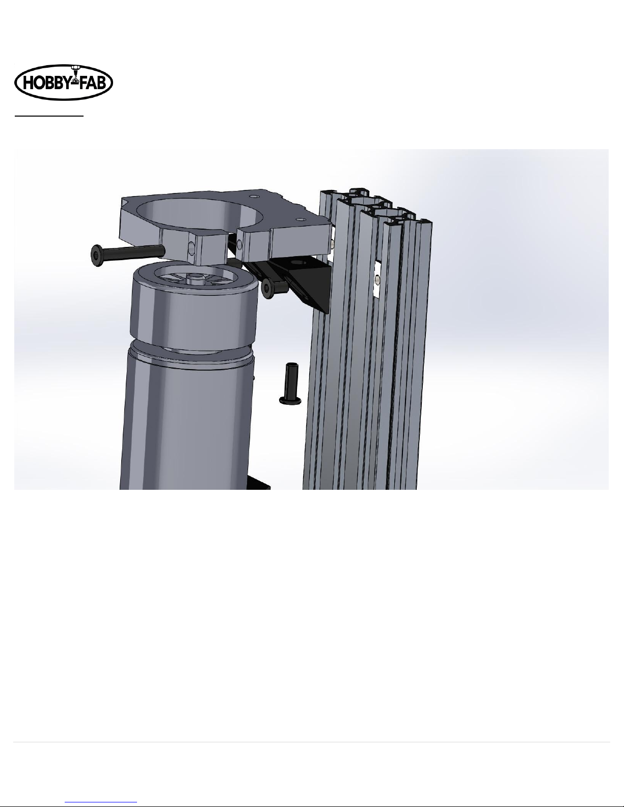
The M5 x 30mm bolts are pre-installed in the clamps.
600W upgrade:
The 600w spindle upgrade is mounted in the same fashion. The builder will also find the 600w power supply in step one.
Page 3
OX Revised Build Instructions Rev 4.5 09/29/2018
3 | P a g e
Laser upgrade:
The spindle clamp with the M3 bolts installed will need to be the bottom clamp, see the end of this document for install.
Exploded View. M5 x 8 bolts go into Tee-nuts, M5 x 15 go into V-Slot.
Note here we are installing the black 90s on the inside, facing towards each other between the clamps, if this is difficult they can
be installed on the outside (top and bottom) of the clamps.
1. Slide the clamps over the spindle motor (these are a tight fit, you can open them with slight hand pressure to install over
spindle).
2. The clamps should ride at the top and bottom of the spindle, the bottom clamp should be approximately 40mm from the
bottom of V-Slot extruded aluminum.
3. Loosely install the M5 x 30 bolt in the spindle clamps and tighten at the last step. Perform on a flat surface so both clamps
are oriented the same direction.
4. Slide Tee-nuts in V-Slot
5. Install M5 x 8mm bolts through black 90 brackets into tee-nuts in V-Slot loosely.
6. Install spindle clamps to black 90 brackets with M5 x 15mm bolts.
7. Once all is aligned, tighten M5 x 8mm, M5 x 15mm, and M5 x 30mm bolts.
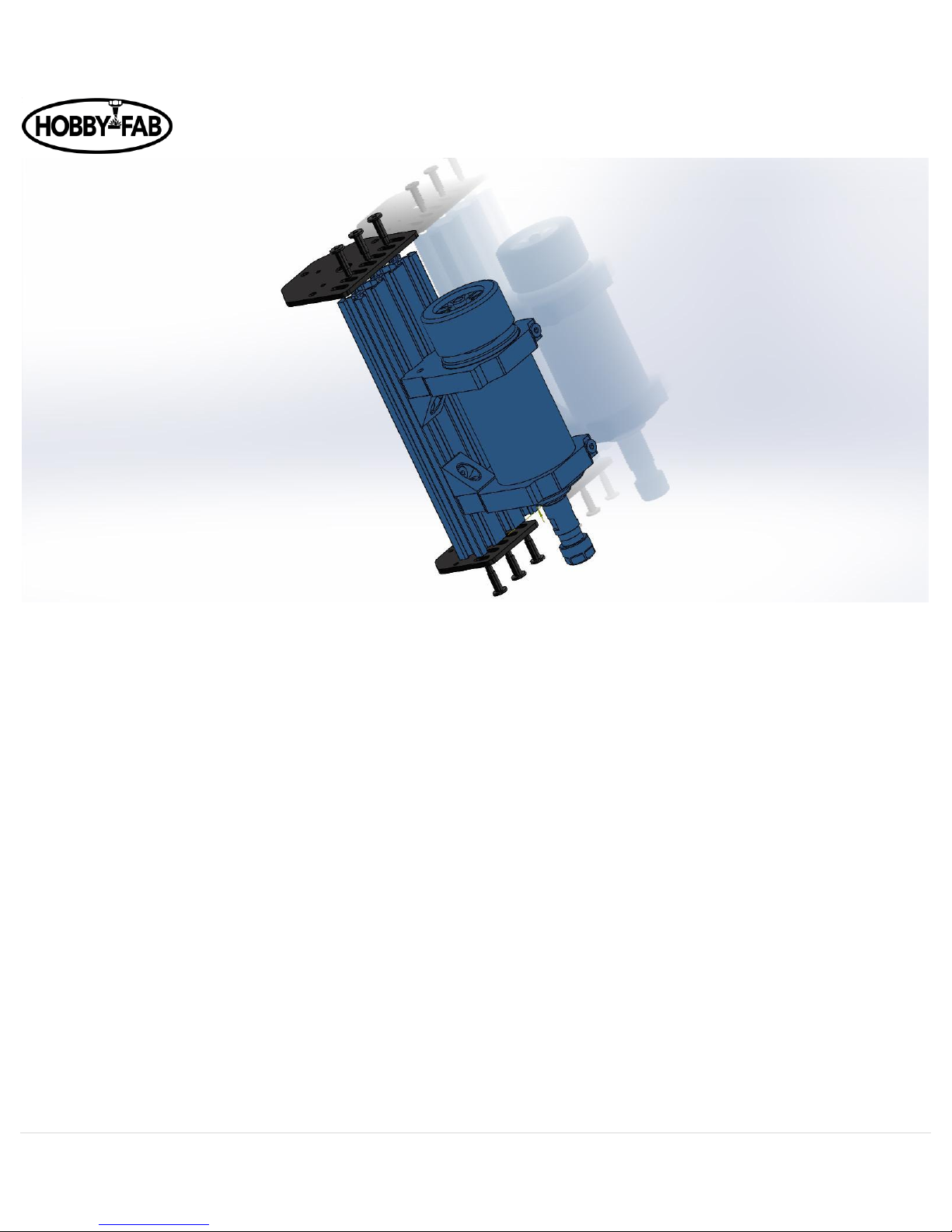
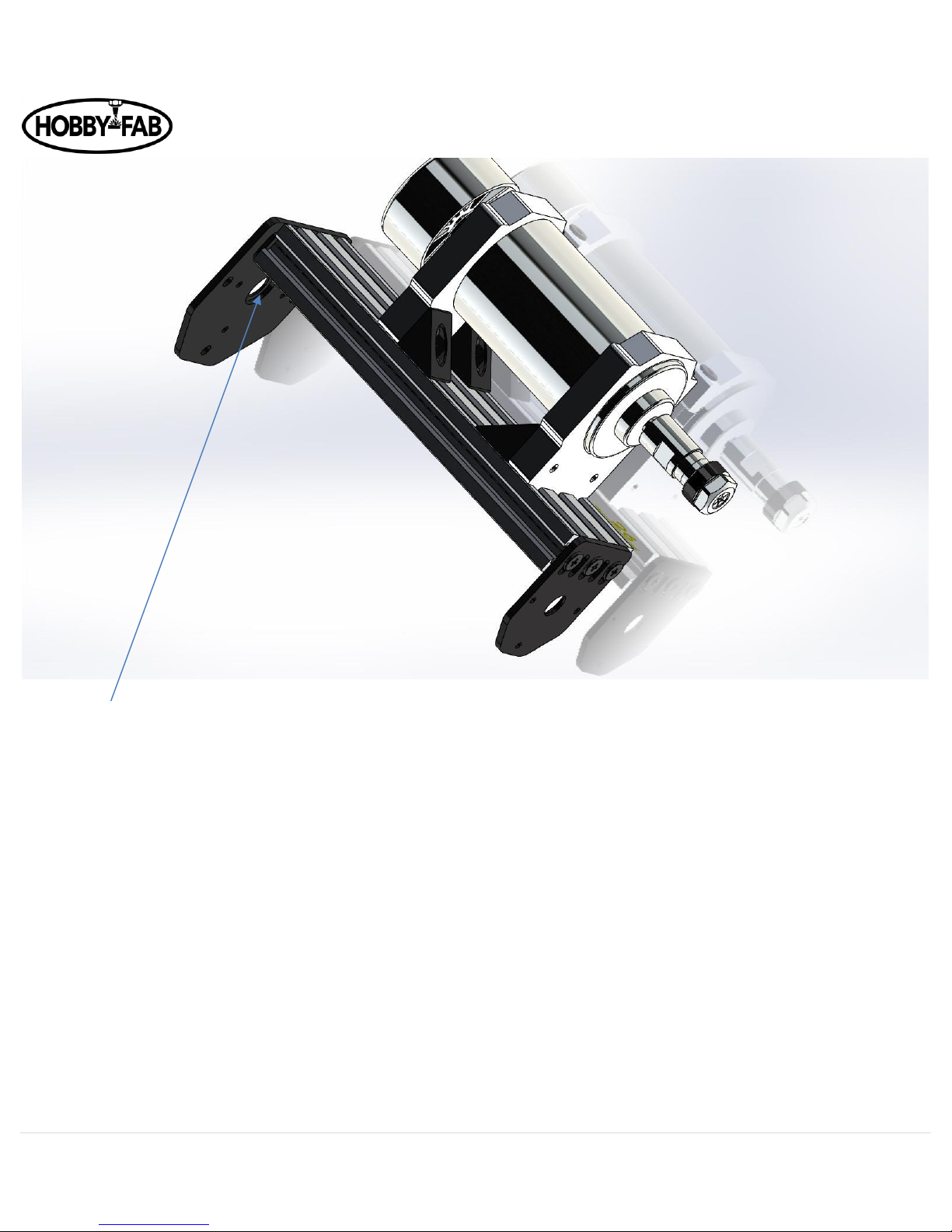
Now we install the threaded rod plates.
Page 4
OX Revised Build Instructions Rev 4.5 09/29/2018
4 | P a g e
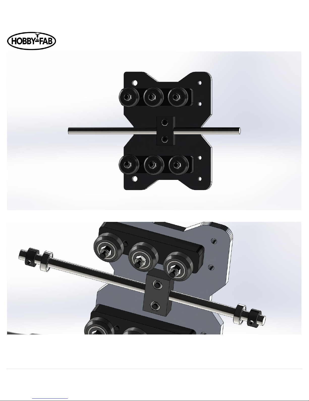
8. The smaller plate goes on the bottom, the bearing recesses (on the threaded rod plates) face each other. Install with 3 qty
(per side) self-tapping screws and leave loose. Note, we provide a screw driver, but the self-tapping screws are much
easier to set with a drill motor.
9. Now that the self-tapping screw threads have been set, you will need to remove either the top threaded plate or the
bottom threaded plate for step 3. It is easier to set the threads before we do the final assembly, hence doing it here then
removing them for the final assembly.
We are now completed with this step; the assembly can be set aside.
Page 5
OX Revised Build Instructions Rev 4.5 09/29/2018
5 | P a g e
Bearing recess
Page 6
OX Revised Build Instructions Rev 4.5 09/29/2018
6 | P a g e
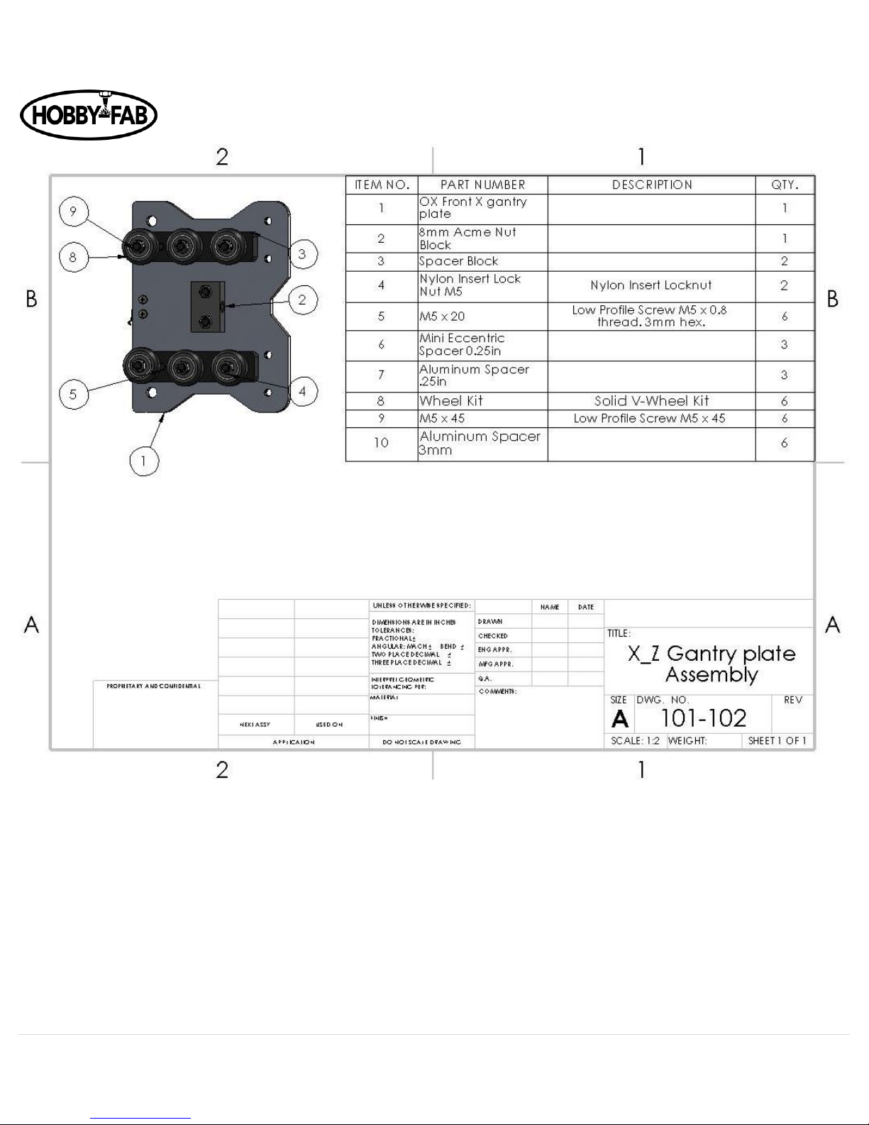
Step 2:
X_Z-Axis gantry plate assembly:
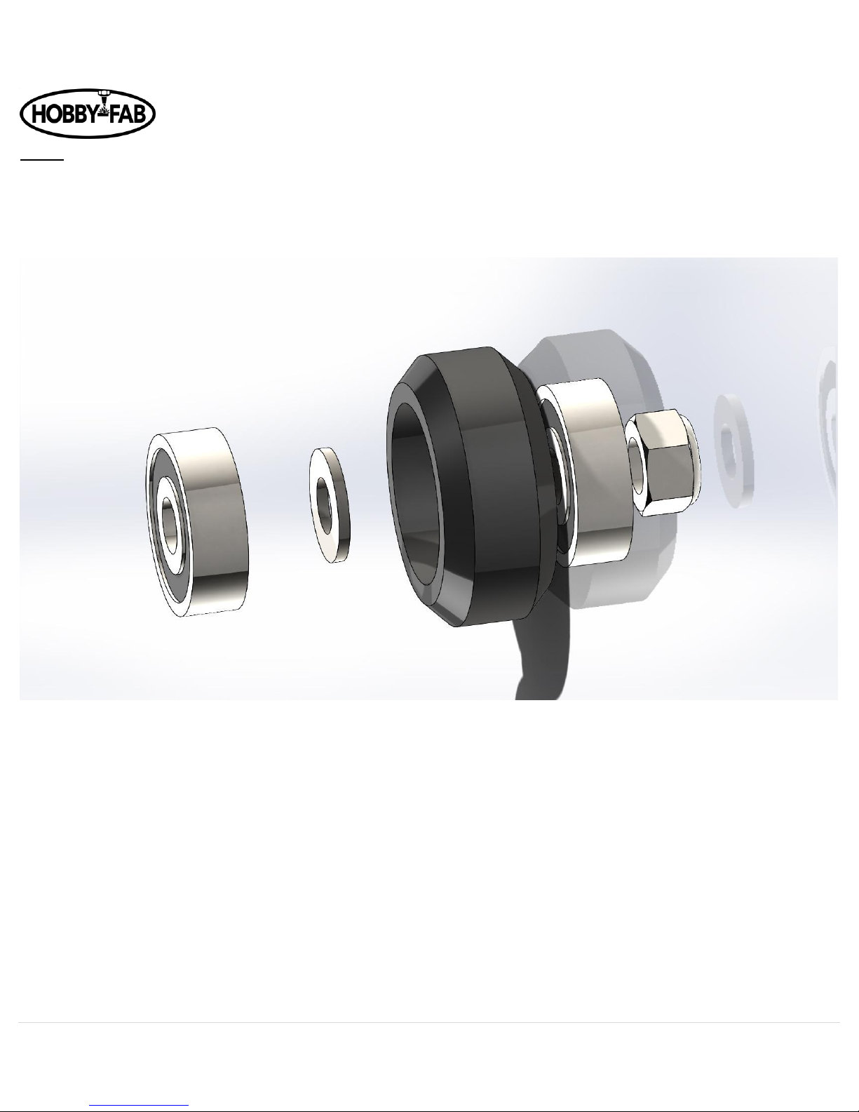
Before we begin this step let us look at how to assemble a wheel assembly. Note the package comes with the bearings and shims
loose. You will need to build the wheel kits. See here:
Bearing, shim, wheel, bearing. In some instances, the additional shim is required outside the wheel, the extra shim is not used in
this build. Do not use both shims inside the wheel. If the additional shim is required, the build instructions will indicate where to
put them.
After you build at least 6 qty wheel kits it is time to continue the X_Z axis build.
Page 7
OX Revised Build Instructions Rev 4.5 09/29/2018
7 | P a g e
The limit switch will face down. This is what will be considered the Z limit switch.
Page 8
OX Revised Build Instructions Rev 4.5 09/29/2018
8 | P a g e
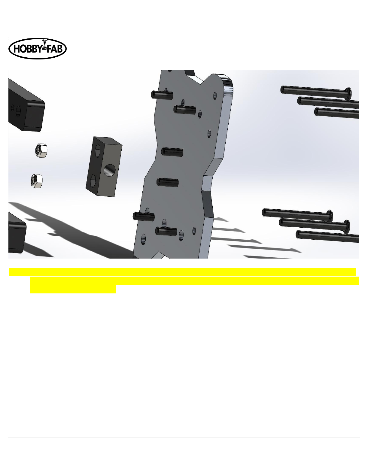
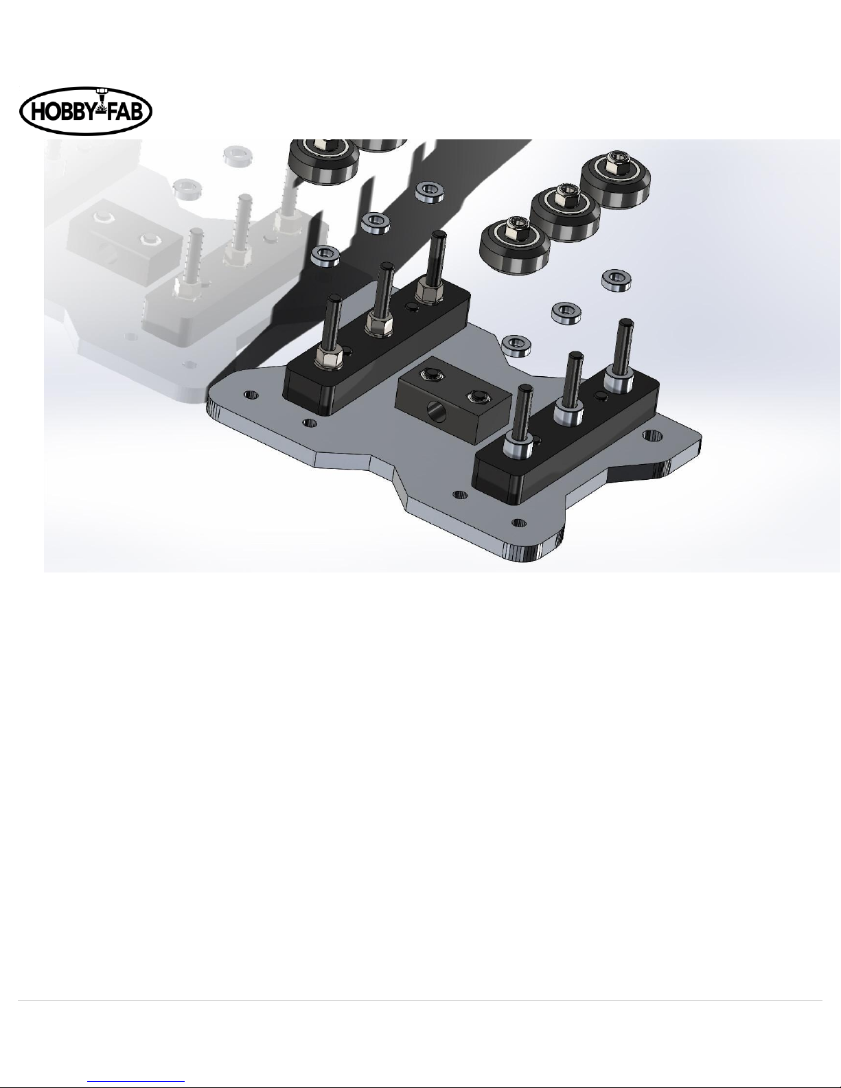
1. Begin by installing M5 x 20mm bolts in the center two holes, and the smaller holes as shown here:
*NOTE: We added a Z limit switch during the writing of these instructions. The gantry plate has since been modified in shape. The
sharper corners face towards the bottom of the Z axis. The limit switch should be installed on the side of the plate that the
bolt heads (not threads) are on. The images used will show the old profile of the plate in some instances, such as above.
Page 9
OX Revised Build Instructions Rev 4.5 09/29/2018
9 | P a g e
2. Next install 2 qty M5 nuts into the plastic ACME nut block. Note one side has cut outs for the nuts.
Page 10
OX Revised Build Instructions Rev 4.5 09/29/2018
10 | P a g e
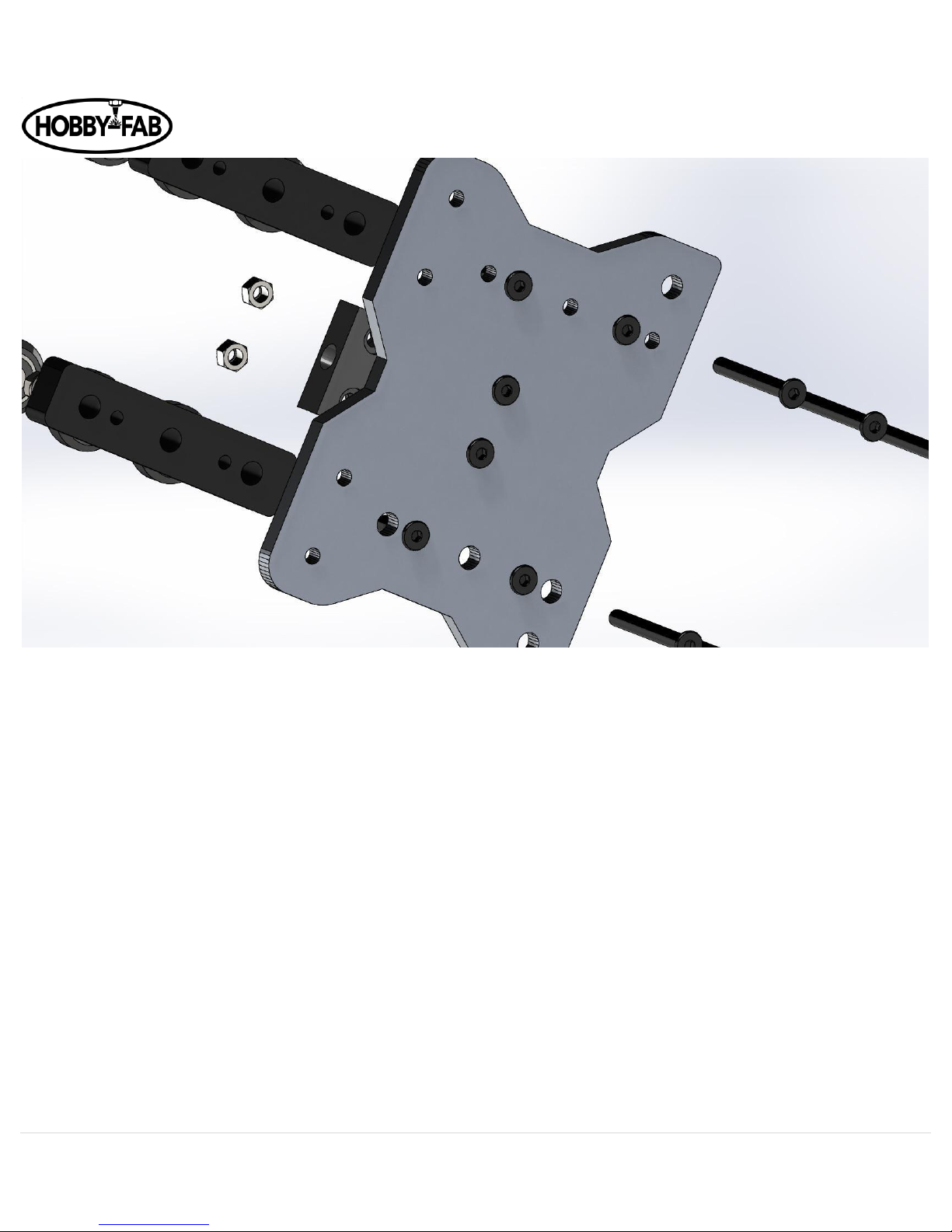
3. Tighten the M5 x 20 bolts holding the black plastic ACME nut block on, snug, do not crush the plastic nut… it is possible!
The bolts need to be tight, not torqued.
4. Next install the spacer blocks (long black pieces) there are threaded holes that the M5x20 bolts will affix to as shown
above.
5. Afterwards slide the M5x45 bolts into the holes in the back of the plate, through the spacer blocks as seen here:
Page 11
OX Revised Build Instructions Rev 4.5 09/29/2018
11 | P a g e
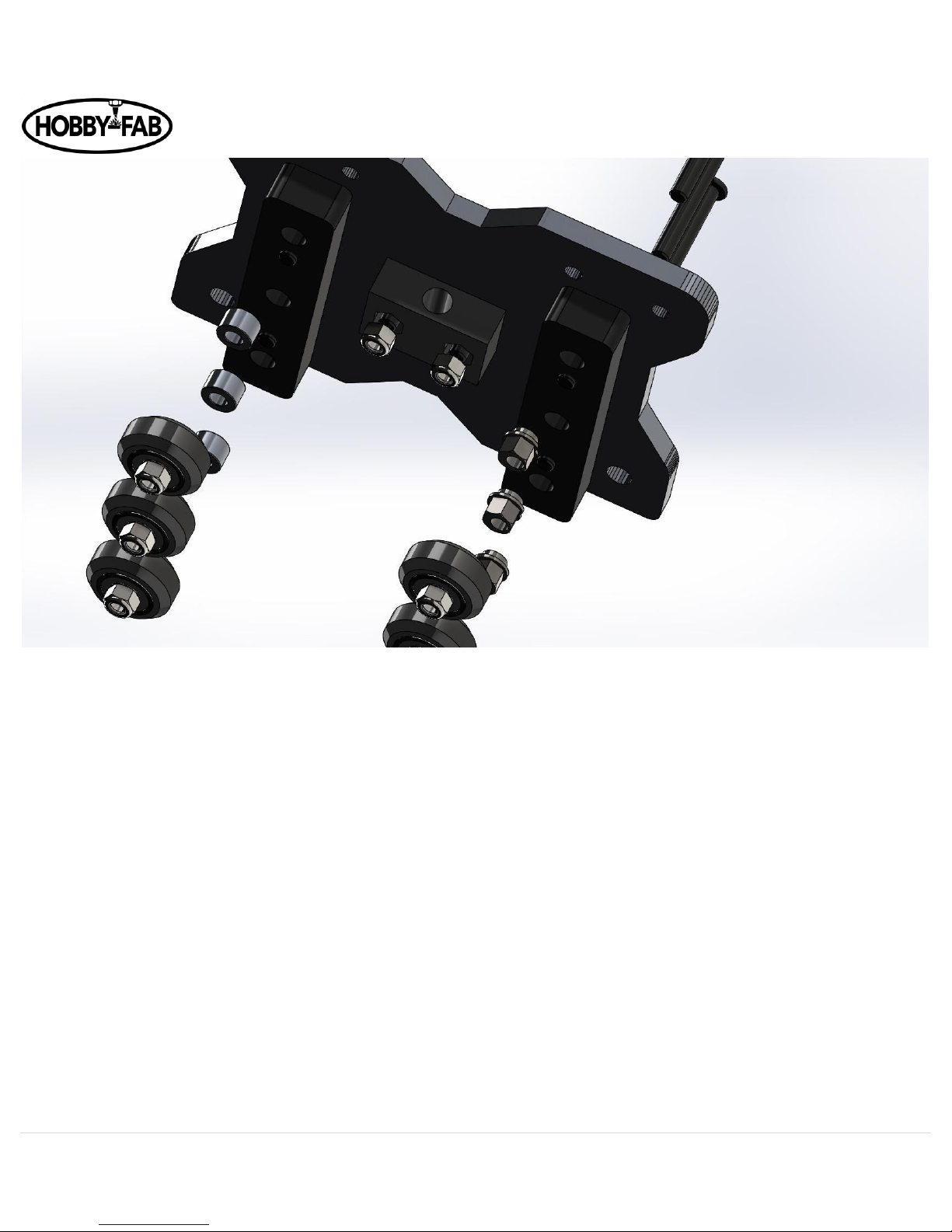
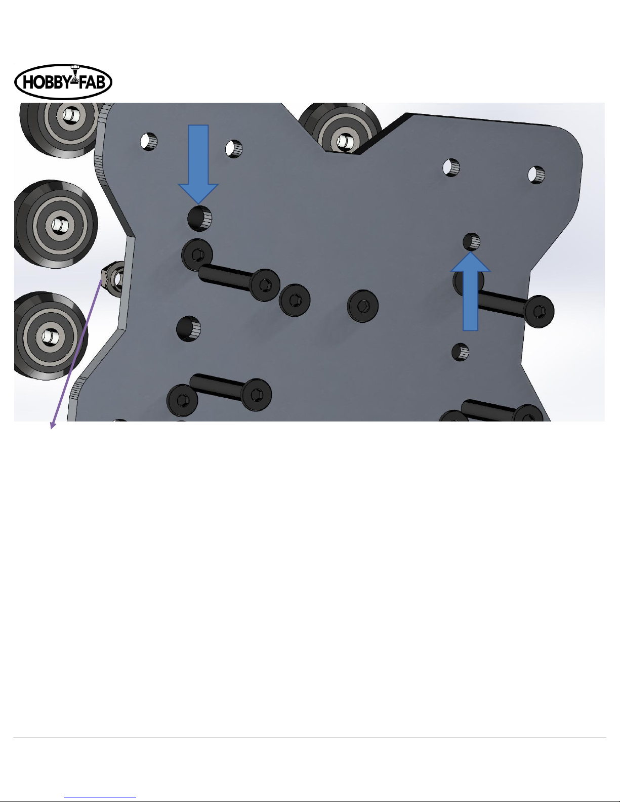
6. Now we will install eccentric spacers on one spacer block and plain spacers on the other. Next install the thinner spacers
(3mm) on top of the eccentric and standard spacers. The eccentrics (later) will allow for us to remove slack from the drive.
Before installing the eccentric spacers, note that one set of holes on the rear of the X gantry plate is larger than the other.
Install the eccentrics on the larger hole set:
Page 12
OX Revised Build Instructions Rev 4.5 09/29/2018
12 | P a g e
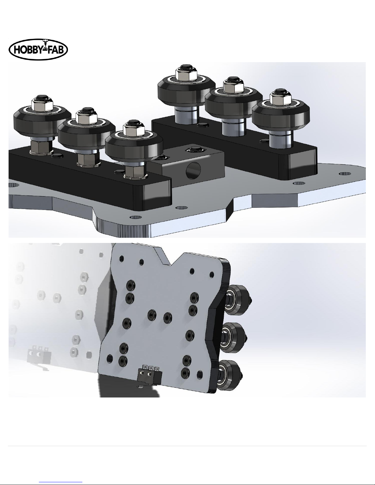
7. Install the eccentrics with the cut-out (on the flange of the eccentric spacer) facing towards the outer edge of the plate.
8. Install the wheels and snug up the M5 nuts holding the wheels onto the M5 x 45mm bolts.
Page 13
OX Revised Build Instructions Rev 4.5 09/29/2018
13 | P a g e
Page 14
OX Revised Build Instructions Rev 4.5 09/29/2018
14 | P a g e
Step 3
Complete X_Z gantry assembly
In this step, we will build the X_Z gantry assembly.
1. Begin by installing the ACME rod in the ACME nut block from step 2. (NOTE) The ACME rod is in bottom of the
12”x12”x12” square box that all the parts came in.
Page 15
OX Revised Build Instructions Rev 4.5 09/29/2018
15 | P a g e
2. Install a 688zz bearing and lock collar on each end. Reverse order shown below, lock collar goes on first.
3. Position the Z axis from step one (with one removed threaded rod plate) over the wheels and slide into place.
Be cautious of the tension between the wheels and the 20x80, if it is too tight make sure the eccentrics are properly
placed.
Page 16
OX Revised Build Instructions Rev 4.5 09/29/2018
16 | P a g e
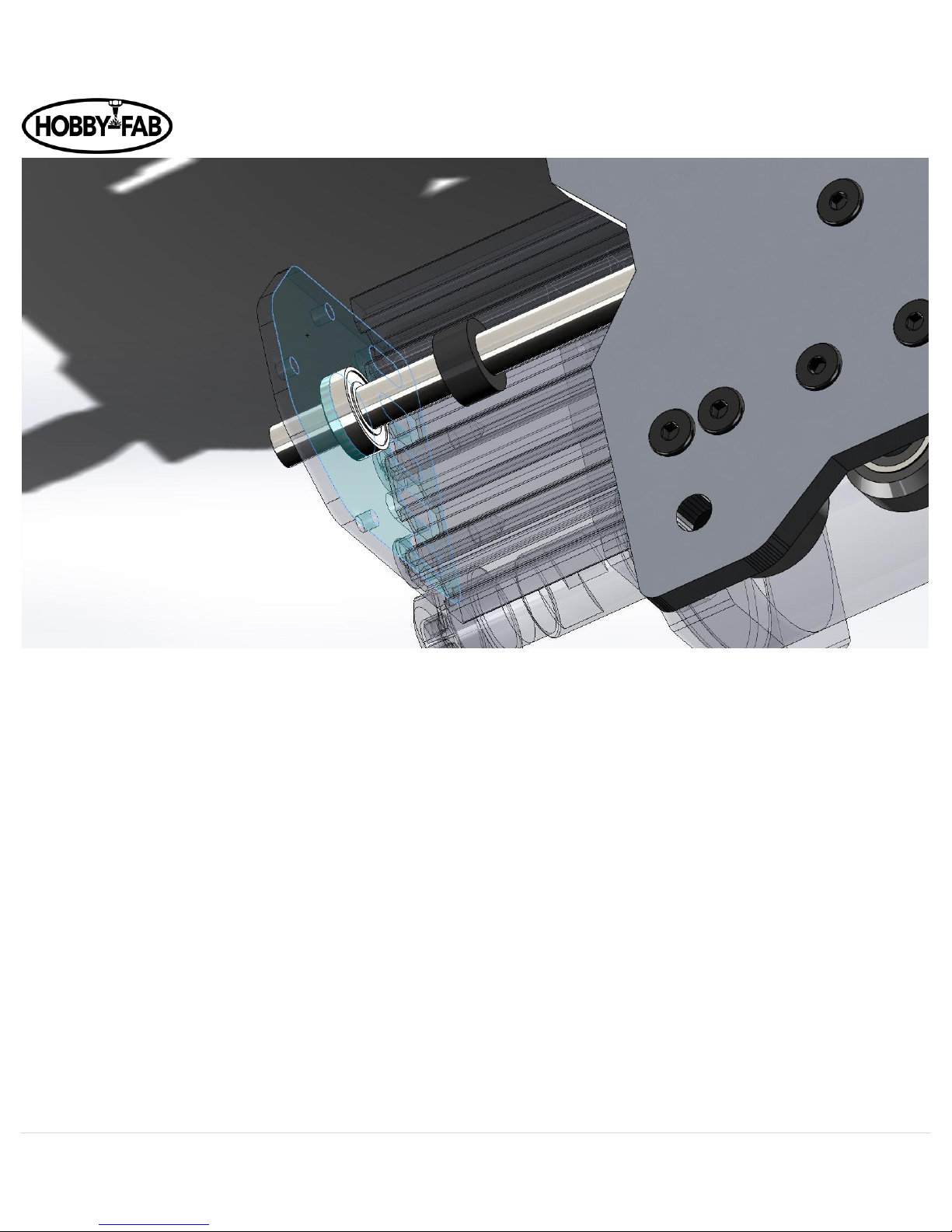
4. Next, with the screws loose on the threaded rod plate, we will align the bearings with the recesses in the threaded rod
plate.
5. Push the bearings into the recesses of the threaded rod plates, then tighten the threaded rod plates in place.
Page 17
OX Revised Build Instructions Rev 4.5 09/29/2018
17 | P a g e
6. Once the threaded rod plates are tightened down, lock the bearings in place with the lock collars. NOTE: you will need to
leave about 2mm of ACME hanging out of the bottom of the lower (smaller) threaded rod plate. The above pictures shows
an exaggerated amount hanging out for display.
Page 18

OX Revised Build Instructions Rev 4.5 09/29/2018
18 | P a g e
7. Check to make sure there is little to no play when you turn the ACME by hand. Also check to make sure the
ACME does not bind when turning by hand. If it does either adjust the lock collars or threaded rod plates to remedy this.
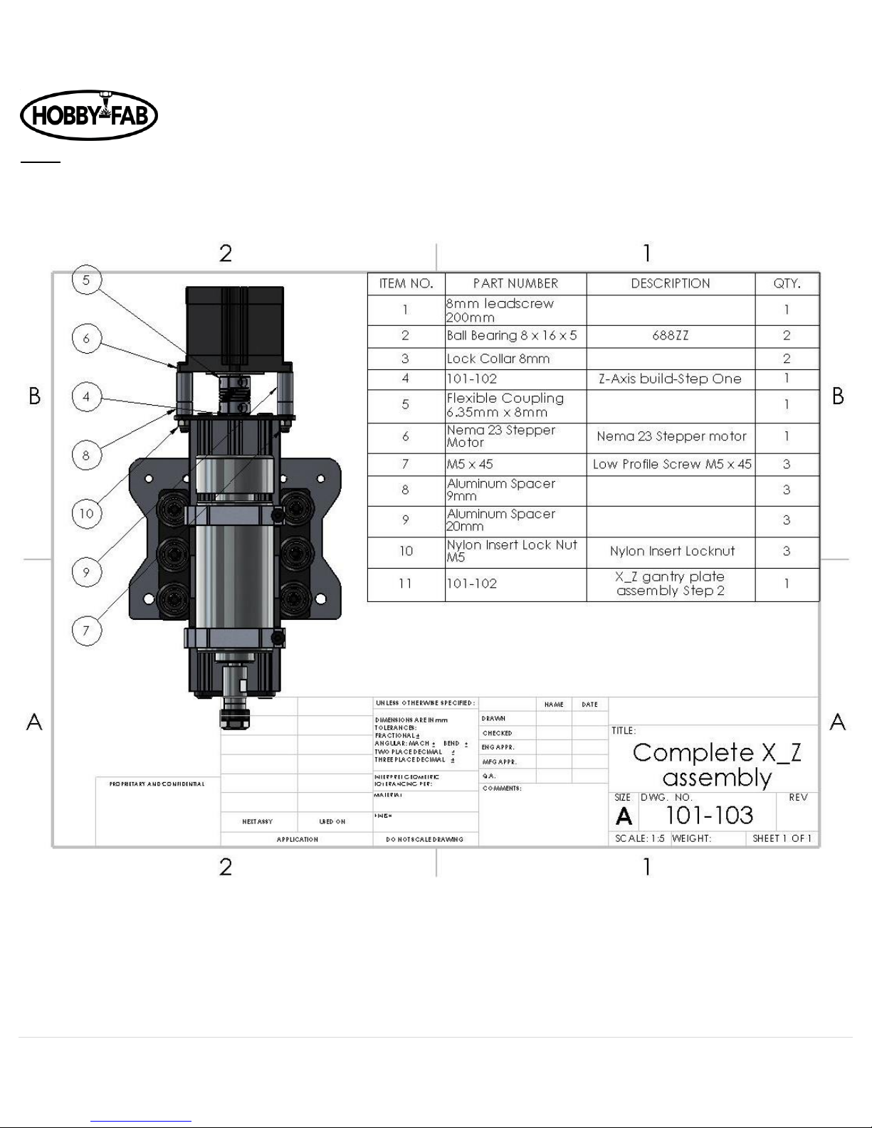
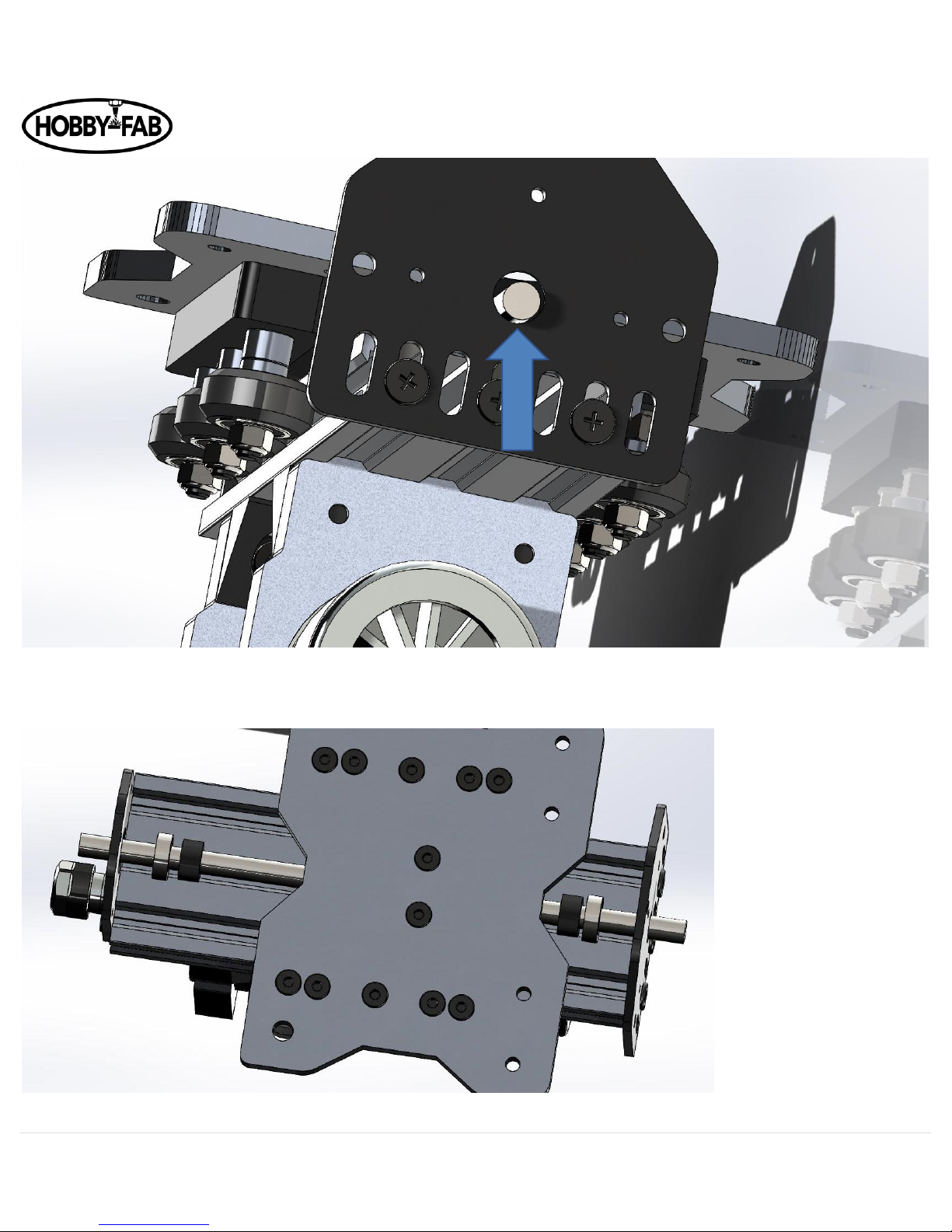
8. Next install the 6.35mm x 8mm coupler on the ACME rod. This goes on the top, the side with the larger threaded rod
plate. Slide the coupler down on the ACME till it stops and tighten the lower set screw on the lock collar.
Page 19

OX Revised Build Instructions Rev 4.5 09/29/2018
19 | P a g e
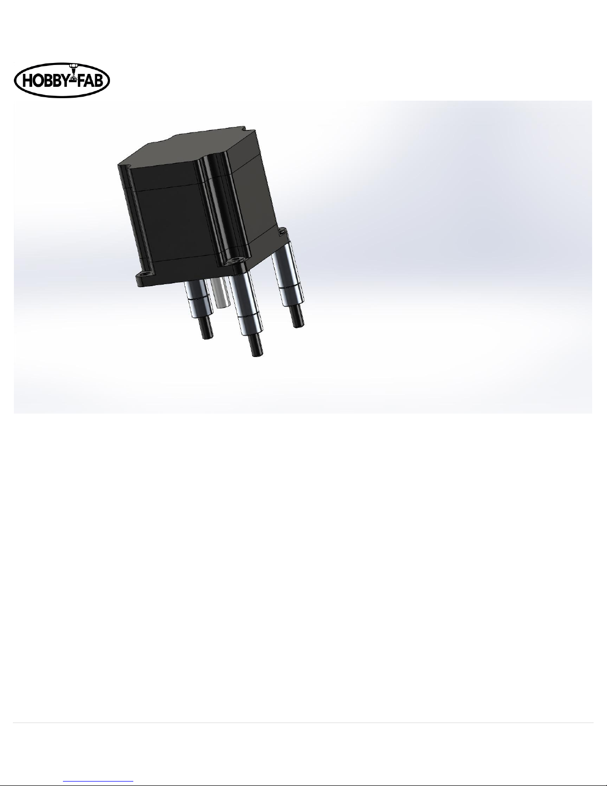
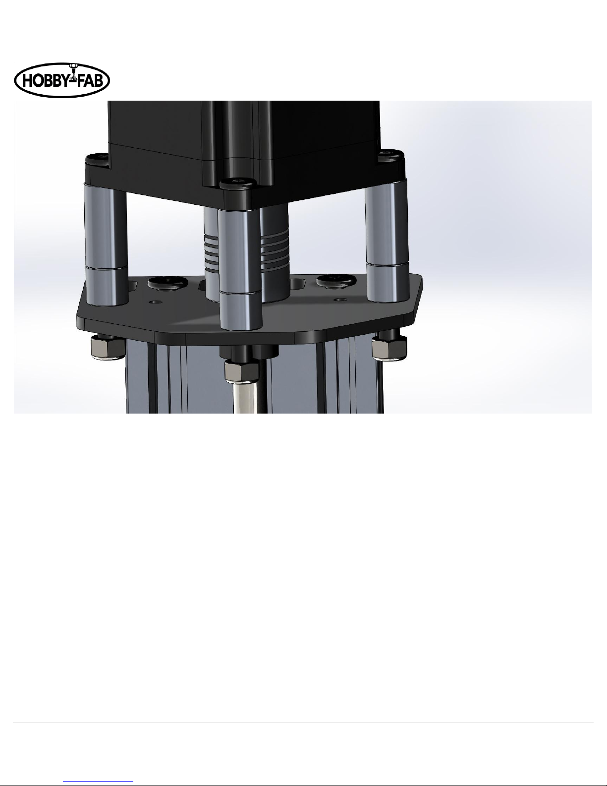
9. Grab the NEMA 23 stepper motor install 3 qty M5 x 45mm bolts in any three holes, slide one each 20mm spacer and nine
mm spacer over each bolt.
Page 20
OX Revised Build Instructions Rev 4.5 09/29/2018
20 | P a g e
10. Now slide the stepper motor shaft into the coupler and run the three bolts into the matching holes in the threaded rod
plate.
11. Follow this with installing three qty M5 nuts and tightening the coupler onto the motor shaft.
Note: The spacers 20 and 9mm may be exchanged for 3 qty 1.5” spacers.
Page 21
OX Revised Build Instructions Rev 4.5 09/29/2018
21 | P a g e
Tighten the M5 nuts to secure the motor.
12. Recall the eccentric spacers installed on one of the spacer blocks above. It is now time to give these a turn and take the
side to side slack out of the Z axis. When installed we did so with the cutouts facing the outside of the plate, as seen here:
Page 22
OX Revised Build Instructions Rev 4.5 09/29/2018
22 | P a g e
Taking the 8mm combination wrench turn each eccentric 1/8 of a revolution of a turn at a time. The wheels will get closer to the
20x60x180 extrusion. Do the top eccentric, middle, bottom. Physically feel the play in the wheel. If there is a lot of play, i.e. you
can turn the wheel freely do another 1/8 of a revolution turn. Repeat till all three wheels on the left side and right side of the
20x60x180 extrusion all slightly drag. DO NOT OVER-TIGHTEN, you can damage the wheel by tightening them too much. The
wheels should not lock on the metal, just rub.
The X_Z gantry is now complete.
Page 23
OX Revised Build Instructions Rev 4.5 09/29/2018
23 | P a g e
Step 4
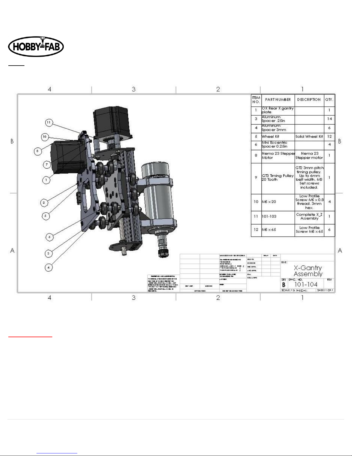
X gantry assembly
Note, again limit switches were added to the scope of the OX kit, some images below will not show the limit. The limit switch gets
installed on the side of the head of the bolts as shown here:
Revision update:
In May of 2018 Hobby-Fab/SMW3D made a change to the motors and made wiring easier. The builder will notice the barrier
blocks, motors, and limits in this step. The change removes the motor mounting hardware of M5 x 20s and M5 nuts as they are no
longer needed. Four quantity M5x10 are now used. This applies to step five as well.
Page 24

OX Revised Build Instructions Rev 4.5 09/29/2018
24 | P a g e
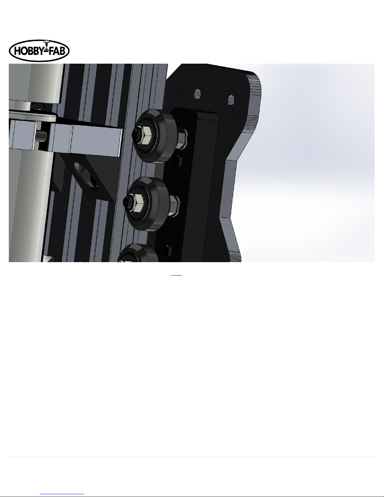
The rear X gantry plate will receive six qty M5 x 65mm bolts.
NOTE: If you purchased the Suckit dust boot, remove the arms from packaging and install them now. These are installed on the
front plate and on the M5x65 bolts. As shown below:
Page 25

OX Revised Build Instructions Rev 4.5 09/29/2018
25 | P a g e
Continuing.
Slide these through the rear plate as shown. Slide a .25” spacer over the top bolts, and .25” eccentric spacers over the bottom
bolts.
Page 26

OX Revised Build Instructions Rev 4.5 09/29/2018
26 | P a g e
Next, install six-wheel assemblies over the bolts, followed by a .25” spacer AND 3mm spacer. Follow with another six wheels and
matching .25” plain spacers and eccentrics as done in the beginning.
Page 27

OX Revised Build Instructions Rev 4.5 09/29/2018
27 | P a g e
Install the X_Z assembly onto the front of the bolts and loosely tighten the M5 nuts to hold everything together. Do not snug the
nuts down to the front of the X_Z plate yet as it will make installing the extruded aluminum difficult, we simply want to hold the
assembly together.
Note you can install the M5 x 65mm bolts either direction with the head of the bolts on the spindle side or the back side.
Page 28

OX Revised Build Instructions Rev 4.5 09/29/2018
28 | P a g e
Next install a GT3 pulley loosely onto the NEMA 23 with the shoulder of the pulley closest to the motor.
Page 29

OX Revised Build Instructions Rev 4.5 09/29/2018
29 | P a g e
The GT3 pulley should be a distance away from the top threaded rod plate by a distance equal to the thickness of a piece of paper.
Use a piece of paper as a gauge and tighten the set screw on the pulley to the shaft of the NEMA 23 stepper motor.
Lastly, the eccentrics on the bottom axles of this assembly, turn till the notches face up. Shown facing down here for ease of
viewing.
Page 30

OX Revised Build Instructions Rev 4.5 09/29/2018
30 | P a g e
Step 5
X_Y gantry assembly
Remove the X gantry extruded aluminum, the length will be based on the kit size you chose. It can be noted which bundle the X is
because it contains two qty 20x60 and one 20x40 that are all the same length.
For this demonstration, we will use the 500x750 build so the image can fit better on the screen.
A quick note, when we say 20x60 we are referring to the dimensions of the extruded aluminum in 20mm squares. A 20 by 60 is a
20mm wide by the 3 x 20mm boxes tall. An easy way to see this from the end is each 20mm box has a hole in the center of it.
Page 31

OX Revised Build Instructions Rev 4.5 09/29/2018
31 | P a g e
Carefully and slowly insert the two 20x60 extrusions into the X_Z assembly. If it is hard to install the assembly onto the 20 x60
make sure the eccentrics on the bottom of the X_Z assembly are facing towards the top of the assembly.
Install a Y gantry plate on the end of the 20x60s using self-tapping screws. Follow with the rear 20x40 before completely
tightening the self-tapping screws. IF the rear 20x40 is short you have mixed the bundles of aluminum. Look for the 20 x 40 that
exactly matches the 20 x60 length.
Page 32

OX Revised Build Instructions Rev 4.5 09/29/2018
32 | P a g e
Note: Limit switch stop can be added here. A drop-in tee nut, M5 x 30mm bolt, and 20mm spacer will be assembled and inserted
here. On the back of the 20x60 on the LH rear side, about 20mm(~1”) away from the gantry plate install in the middle slot:
Page 33

OX Revised Build Instructions Rev 4.5 09/29/2018
33 | P a g e
This can always be adjusted later, tighten the bolt down for now in the approximate location shown above. The limit switch arm
should contact the 20mm spacer.
Page 34

OX Revised Build Instructions Rev 4.5 09/29/2018
34 | P a g e
Next, install a NEMA 23 Stepper motors on each Y gantry plate with M5 x 20mm bolts ad secure with M5 nuts.
See revision note above pertaining to motor mounting.
Also note limit switch installed on back of Y gantry plate edge.
Install the GT3 pulleys on the NEMA 23 stepper motors. Leave the set screw loose for now. After installing the belts in the final Y
assembly, align the pulley with the belt and tighten the set screw.
Page 35

OX Revised Build Instructions Rev 4.5 09/29/2018
35 | P a g e
Install the upper wheels on the Y gantry plate with .25” spacers. The lower wheels get installed with .25” eccentric spacers. The
bolts are installed with M5 x 30mm bolts and M5 nuts. Again, turn the eccentric spacers to give the most room.
Page 36

OX Revised Build Instructions Rev 4.5 09/29/2018
36 | P a g e
You should be able to now set the Z, X, Y gantry on a table and tighten the X Gantry eccentric spacers (the ones located on the
bottom of the X_Z assembly assembled in step four) tighten, by small even turns, both eccentrics on the bottom of the X gantry.
You want the wheels to slightly drag, but not grab.
Page 37

OX Revised Build Instructions Rev 4.5 09/29/2018
37 | P a g e
Step 6
Y and Base gantry assembly
GT3 Belt found in this step __ Ft (based on size)
+4 tee-nuts per size larger build (for center supports)
+4 cast 90s per size larger build (for center supports)
+4 M5 x 8mm bolts per size larger build (for center supports)
There will be other items in the step 6 box, these will be itemized below as part of the electrical BOM.
We will continue to expand on the mechanical assembly.
Again, for this example we will use the 500 x750 build. We will grab the two 20x80x750 extrusions, note again these should be
bundled together. Gently slide them into the wheels on the Y gantry plates.
Page 38

OX Revised Build Instructions Rev 4.5 09/29/2018
38 | P a g e
Next grab the two 20x40 pieces bundled together that are very slightly shorter than the X gantry, in this model the X gantry is 500
the support pieces that will go in the base are 496mm.
Page 39

OX Revised Build Instructions Rev 4.5 09/29/2018
39 | P a g e
Using the 5-hole 90s from this step install them between the 20x80 and the 20x40. Use Tee-nuts with M5 x 10 bolts in the 20x40
and self-tapping screws in the 20x80.
Page 40

OX Revised Build Instructions Rev 4.5 09/29/2018
40 | P a g e
Use a speed square or some device that has a known good 90-degree angle and true the corner of the build, then tighten the
screws down on all four corners.
The base should be very sturdy now.
Next, we need to add supports for the spoiler board.
The 500 x750 build has one center support, the 750 x 1000 has two, the 1500 x1500 build has three.
The support(s) will be the length of the Y axis minus 40 mm and we normally remove another two mm to allow an easy fit. This
build will have one support 708mm long.
The support(s) should be equally spaced under the bed of the build. They are constrained by cast aluminum 90 degree brackets.
Before sliding in the center support slide tee-nuts into the top slot of the rail. And attach the cast 90s loosely. On the opposite side
of the front support of where you installed the 5-hole 90s slide tee-nuts in to mount the center support(s).
Page 41

OX Revised Build Instructions Rev 4.5 09/29/2018
41 | P a g e
Install all cast 90 degree brackets by M5 x 8mm bolts, square and tighten. 8 qty M5 x 8 used in this example here.
Page 42

OX Revised Build Instructions Rev 4.5 09/29/2018
42 | P a g e
Now lets us add the Y limit switch stop. Just as we did earlier use a drop-in tee-nut, spacer and bolt and set the stop in the rear of
the 20x80 Y run on the side with the limit switch. The spacer is 20mm tall and the bolt is a M5 x 30, see below, this is held on with
a drop-in tee-nut.
Page 43

OX Revised Build Instructions Rev 4.5 09/29/2018
43 | P a g e
Now it is time to install your spoiler board. The spoiler board is 1/2” MDF that can be purchased at any lumber yard or home
goods store. Most will cut it to size for you if request. Measure the inside of the frame from one 20x80 Y to the other 20x80 Y, this
is the width you need. Measure inside of 5-hole 90 to 5-hole 90 this is the length you need.
1500mm builds. You can source a full spoiler board at specialty wood shops. Another method is to use regular sheets of ¼” MDF
and put a splice in one direction, for instance the Y to completely fill the bed. Follow with a second ¼” piece of MDF on top of the
first with the splice running in the opposite direction, for instance the X. Adhere these two together with a nail gun or adhesive.
Page 44

OX Revised Build Instructions Rev 4.5 09/29/2018
44 | P a g e
Now we need to run belts.
Tee-nuts and bolts are used to secure the ends of the belts, wrap the belt under the wheels and over the pulley:
Page 45

OX Revised Build Instructions Rev 4.5 09/29/2018
45 | P a g e
Run it to the end of the gantry and slide a tee-nut over it. Tee nuts are used on the X gantry. Do not over tighten, we do not want
to go through the belt with the bolt, just snug against it. Use an M5 x 8mm bolt.
Page 46

OX Revised Build Instructions Rev 4.5 09/29/2018
46 | P a g e
End of the Y gantry shown above, give it a good pull and tighten the M5 bolt in the tee-nut. Don’t get too tight! You can go all the
way through the belt if not careful, we do not want to go through the belt, just snuggly against it.
If you didn’t already, align all pulleys and tighten the set screws now.
Congrats, your machine is mechanically complete.
Page 47

OX Revised Build Instructions Rev 4.5 09/29/2018
47 | P a g e
Electronics Section.
There are three possible configurations of electronics. Please see below instructions dedicated to groups based on the one you fit
into.
1. Those who want to use their own controller.
2. Those who purchased the Simple all in one control box.
3. Those who purchased the PRO all in one control box.
Group 1,2 ,and 3 Install your electronics (controller, control box, power supply etc.) as close to the end of the Y cable chain, let us
assume we are going to install the controller and such on the left-hand side of the machine looking at it.
The below is an example of how you want to run your wires.
Group 1: We suggest 6 conductor wire 22awg for the steppers.
Group 2 and 3: Install the control box mid-way down the Y (side) of the build. Do not use the full cable chains down the side of the
build, the cable chain should be half the length of the Y; for instance if you have a 1500mm build the Y cable chain should be 750mm
and the box mounted at the mid-section.
Group 2 and 3: These will be the included wires in the control box packaging. You will have four long leads, one will be shorter than
the other three. The shorter run should be your Y axis closest to the control box, like the orange line below. Ideally this will be your
Y limit switch side.
Group 2 and 3: All wires for the box must be ran through the cable chains from the control box to the plate. The end connectors
will not fit through the cable chains, so they must be ran from the box to the plates.
Page 48

OX Revised Build Instructions Rev 4.5 09/29/2018
48 | P a g e
Orange illustrates Y motor opposite the control box.
Blue illustrates how we want to lay out the X, Z, and 2-wire for the spindle.
Red illustrates how we want to lay out the Y closest to the controller.
The opposite side Y should run under the cable chain and jump through the bottom of the cable chain prior to exit.
REVISION NOTE Group 2 and 3:
Kits past May 2018 will use barrier blocks on each plate. Simply connect to the barrier blocks, match color to color, for example
red to red, green to green, etc.
Contr.
Box
Y
X
Page 49

OX Revised Build Instructions Rev 4.5 09/29/2018
49 | P a g e
The opposite side Y motor from the control box side should run under the cable chain and jump through the bottom of the cable
chain prior to exit.
Group the X,Z and Spindle wires and run them through a cable chain to exit the Y gantry plate opposite the one shown above.
Page 50

OX Revised Build Instructions Rev 4.5 09/29/2018
50 | P a g e
CABLE CHAIN LENGTHS:
Group 1 2 and 3:
Cable chain lengths depend on the size of your build.
If you have a 500mm X axis then remove half the cable chain prior to installing. If you have a 1500mm build, combine 1.5 cable
chains to make the X Axis. All builds the Y cable chain should be half length of the Y axis meeting the control box that is mounted at
the center of the Y and on the table.
750mm X axis remove 10 or so links.
You can either drill a hole through the side of the end of the cable chain or remove the end connector (see image below) and use
the hole in the side of the connector, this depends on which way you installed the cable chain on the wires. Hold the end of the M5
x 30mm bolt, use a 20mm spacer and install with a M5 nut and tighten in place to the rear X gantry plate.
It was noticed that the spacer that holds the cable chain was too long. A M5x20mm bolt replaces the M5 x 30 and a 9mm spacer
replaces the 20mm spacer. Perfect alignment is found at about 10-11mm distance. Two spacers from the wheel kits can be added
here to get the perfect cable chain alignment with the 20x20 rear brace.
Page 51

OX Revised Build Instructions Rev 4.5 09/29/2018
51 | P a g e
Page 52

OX Revised Build Instructions Rev 4.5 09/29/2018
52 | P a g e
The other end will lay on the 20x40 and is installed with a drop-in tee-nut:
Page 53

OX Revised Build Instructions Rev 4.5 09/29/2018
53 | P a g e
Install the cable chain with a drop-in tee-nut on the 20x40 behind the X gantry and the other end to the rear X/Z gantry plate.
Page 54

OX Revised Build Instructions Rev 4.5 09/29/2018
54 | P a g e
Now, coming out of one side or the other Y gantry plate you should have wires that are connected to the X, Z, and opposite side Y
motors and limit switches.
Connect the last wire to the one Y stepper motor that is not connected. After, run all four wires and the spindle wire through the
remaining cable chain.
Note – If the kit has the optional laser add-on run the laser diode and fan wires at this time as well, see instructions below.
It may be required to break the cable chain into smaller sections to get all the wires through it.
Page 55

OX Revised Build Instructions Rev 4.5 09/29/2018
55 | P a g e
Attach the cable chain to the Y gantry plate threaded hole (9mm spacer, 15mm bolt) as we did earlier on the rear X/Z gantry plate.
Attach the free end to the table with a wood screw.
Page 56

OX Revised Build Instructions Rev 4.5 09/29/2018
56 | P a g e
Now let us connect to the controller, we are showing an M1 here, but the controller may vary. The connections will remain the
same.
Connecting to the control board
Group 1. The following is an example wiring video from when we used to include a M1 control board. You can use this as an example
of how to wire your machine with your controller. https://youtu.be/LhTec1ATZKc
The following example is only for reference. Your controller choice may vary.
Group 2 and 3 Skip to page 65.
Page 57

OX Revised Build Instructions Rev 4.5 09/29/2018
57 | P a g e
X goes to the top connector, Y then Y, then Z is the bottom. The colors of the wires are important! Connect them just as shown here.
The limits will wrap around the other side and are (from top to bottom) X,Y,Z. Notice how the second Y motor has a reversed
connection.
400 watt spindle:
Now connect the PWM connection on the controller to the spindle speed control. Polarity matters!
600 watt spindle:
Connect 0-10V from the M1 controller pins (right above the PWM pins) and ground to the 600 watt power supply. The front of the
600w power supply has 0-10v and ground connections. Polarity matters.
Remove the potentiometer that comes installed on the 600w power supply. Leave the power switch installed, this is required to
enable the 600w spindle.
Page 58

OX Revised Build Instructions Rev 4.5 09/29/2018
58 | P a g e
Run spindle motor wires to the 600w power supply and connect red to M+ and black M-.
Run 110VAC to the 600w power supply in the same fashion as the 48VDC power supply.
Connect the power supply to the controller and spindle speed control
______________________BE VERY CAREFUL OF POLARITY HERE!!!______________________
On the controller GND goes to V- on the power supply, hook negative and positive to the spindle speed control as well from the
power supply.
Hook the spindle to the spindle speed control.
Now connect the USB cable (not provided) to the controller.
Connect the power supply cable to the power supply, Green to Ground, Black to N, White to L.
A fan is included in the kit, plug the fan directly to the power supply and aim it directly at the heatsinks (red metal) on the M1.
400W Plug into this rail, PWM+ and PWM-
600W Plug into this rail, 0-10V and GRN
Page 59

OX Revised Build Instructions Rev 4.5 09/29/2018
59 | P a g e
Plug in the power supply to a wall outlet after checking all connections.
Power down after you have noted lights on the controller and spindle speed control.
There are 3 quantity capacitors included in the kit. If you have problems with noise on the limit switches, install them as shown
here:
Page 60

OX Revised Build Instructions Rev 4.5 09/29/2018
60 | P a g e
Not all will have this issue, but it does occasionally happen.
Page 61

OX Revised Build Instructions Rev 4.5 09/29/2018
61 | P a g e
Page 62

OX Revised Build Instructions Rev 4.5 09/29/2018
62 | P a g e
Communicating with the machine:
Plug a USB cable A to B into the control board and the opposite end into a computer and plug the power supply cable into a 110V
outlet.
Start your computer and open a google chrome window.
Go to this address:
https://cnc.js.org/docs/desktop-app/
Download the appropriate desktop app for your system, OS, windows, etc.
Open CNC.js
Look for a connection window on the top left hand side.
Power the OX machine.
Under port, hit the refresh button, use the drop down to find a USB port that states “Manufacturer FTDI”, select this.
A blue button labeled “Open” is also in the connection window. Click this button.
You should now be connected. You must home the machine prior to jogging around. There is a blue button labelled “Homing” in
the upper right hand corner, click this.
The machine should raise the Z, then lower a bit, then go back up. X and Y axis should follow.
Once homing is complete you can now jog around.
If you jog the wrong direction, you will lock grbl. The system purposely does this to avoid damage. If locked, simply hit the refresh
and unlock buttons located near the homing button.
You are now connected to the machine and it is fully usable!
You can try jogging around, homing the machine, starting the spindle (M3 S1000), etc.
Take time to familiarize yourself with this window. There are a lot of features here. If you want to jog the machine around go to the
upper right-hand window, called Axes, click the down button and the box will expand. Click on the “move” tab and select “1”
Then click any of the direction buttons. The machine should move.
GRBL Settings change:
Example
If an axis such as X, Y, or Z moves in the opposite direction it should you will need to change the “$3” mapping. For an understanding
of this see the GRBL page:
https://github.com/grbl/grbl/wiki/Configuring-Grbl-v0.9
Scroll down a bit and you will see a set of numbers “$1” through “$132”, below this is an explanation of what each does. Related to
the example above, if X moves the opposite direction we tell it, we would need to set “$3=1” based on this information:
Page 63

OX Revised Build Instructions Rev 4.5 09/29/2018
63 | P a g e
Setting Value
Mask
Invert X
Invert Y
Invert Z
0
00000000
N N N
1
00000001
Y N N
2
00000010
N Y N
3
00000011
Y Y N
4
00000100
N N Y
5
00000101
Y N Y
6
00000110
N Y Y
7
00000111
Y Y Y
To make changes, go to the Com screen. Look in the mid-left hand side of the screen. Note it is black with white text.
At the bottom of this box you will see an area where you can type things, type in this box, $$
You will see what your current settings are. Only if an axis is going the wrong direction should you make the below change.
Note that $3=0 out of the list of things there.
Type $3=1
Then type $$
Note that now in your list $3=1, and when you jog the machine X now moves in the opposite direction. If all axis move in the wrong
direction you would type $3=7, for example.
One last thing to check is that the spindle turns the right direction. Type M3 S11000 in the serial port. This should turn the spindle
on at 11000 RPM. Type M5, the spindle stops. Looking down at the top of the spindle, it should turn to the right. If it turns the
opposite direction, switch the red and black wire on the spindle speed control.
Page 64

OX Revised Build Instructions Rev 4.5 09/29/2018
64 | P a g e
The machine is set up and ready to be used! Play around with the $$ settings. Set travel limits, set max velocities and
accelerations.
Have a read on our page about “How to CNC” here: https://www.hobby-fab.com/wordpress/2018/11/12/how-to-cnc/
Read about feeds and speeds here: https://www.hobby-fab.com/blog-post/what-is-the-right-feeds-and-speeds-for-my-cnc-
router-kit-2
There are several example files and getting to know your machine tutorials on our blog. We suggest trying the “First cut” tutorial
as soon as you have the machine set up. You can find these here:
https://www.hobby-fab.com/blog
Explore the machine, explore software, explore all that various things you can create. There is so much to learn and new
opportunities around every corner when you can build the world around you.
Congrats you have completed a nice build, you have now have a tool that you built that can be used to make amazing things.
We love to show off the things our makers have done, once you get comfortable, shoot us some pics of your craftsmanship.
Thank you again for letting be part of your build, don’t hesitate to contact us if you have any questions, we are happy to help!
Please join us on social media
Facebook group https://www.facebook.com/groups/2108778909448986/
Google plus https://plus.google.com/u/0/+HobbyFab
Page 65

OX Revised Build Instructions Rev 4.5 09/29/2018
65 | P a g e
ALL IN ONE CONTROL BOX CONNECTION INSTRUCTIONS
WARNINGS:
Do not connect the 110VAC power cable till all motors are connected.
Do not disconnect any stepper motors while the control box is powered.
Mount the box to something non-conductive. A ground loop can be created between the box and machine if connectivity is
allowed other than intended connections.
Do not place any electronics on top of the control box including 600w PSU/ESC, etc. The noise will cause erratic behavior.
Do not open the control box, wires can be dislodged.
If the shipping box is severely damaged upon receipt, please DO NOT PLUG THE BOX INTO A WALL OUTLET. The box is internally
grounded and fused for both AC and DC but your safety is top priority, a damaged box should not be used. SMW3D, Hobby-Fab
and related affiliates hold no responsibility for damage to equipment or persons by using this product. Be safe, be smart, build!
CARE:
Please clean the intake foam air cleaner about every 10 hours of use.
There are two styles of the all in one control box. One is a simple the other is the PRO. The difference is one requires an external
computer the other does not. The simple will require you to use an external computer and download a gcode sender. The PRO has
an internal computer with a gcode sender pre-installed.
Connections for both PRO and Simple boxes:
Connect all stepper motors to the X, Y, (if using a gantry style machine Y2) and Z. The 6 pin connectors are labelled below. Looking
at the face of the box the connections are, from left to right:
Accessory Port (closest black connector to the E-Stop):
Black/ White = Z probe Yellow/Blue = (+/-) PWM Green/Red = (-/+) 0-10V
Green and red go to the 600w spindle power supply, connect red to the 0-10V connection and green the GRN connection. If you
have a laser Yellow and Blue go to the Red and Black connection of the laser control board (see more below).
Remove the potentiometer and switch that comes installed on the 600w power supply.
Page 66

OX Revised Build Instructions Rev 4.5 09/29/2018
66 | P a g e
Run the spindle motor wires to the 600w power supply and connect red to M+ and black M-.
X Axis:
Black/White = X axis limit switch Yellow/Blue = 1A 1B stepper motor pair Red/Green 2A/2B
Y Axis:
Black/White = Y axis limit switch Yellow/Blue = 1A 1B stepper motor pair Red/Green 2A/2B
YNL: (this is only needed on gantry style machines with two Y motors)
YNL stands for Y axis no limit, the black and white wires are not present on this axis.
Yellow/Blue = 1A 1B stepper motor pair Red/Green 2A/2B
Z Axis:
Black/White = Z axis limit switch Yellow/Blue = 1A 1B stepper motor pair Red/Green 2A/2B
NOTE: If your machine is a kit from us this will directly plug (color to color) into the stepper motors and limit switches.
NOTE: All limit switches are filtered and should be used in the NO (Normally Open) position.
ACC X Y YNL
Page 67

OX Revised Build Instructions Rev 4.5 09/29/2018
67 | P a g e
Power up instructions GROUP 2:
Step 1: Gather laptop or PC and download cnc.js https://cnc.js.org/docs/desktop-app/
Step 2: Connect a USB cable from your computer to the All in one Simple control box.
Step 3: Make sure the E-Stop is “out” this allows power to the control board.
Step 4: Plug the 110VAC cable into the fused connection on the far left.
Step 5: Turn on the master switch.
Step 6: On your computer on CNC.js connect to the machine.
Step 7: Skip to the USE section below.
Power up instructions GROUP 3:
Step 1: Confirm all connections above are made.
Step 2: Make sure the E-Stop is “out” this allows power to the control board.
Step 3: Plug in a USB style Mouse and Keyboard to either USB port on the front.
Step 4: Plug an HDMI monitor into the port on the face.
Step 5: Plug the 110VAC cable into the fused connection on the far left.
Step 6: Turn on the master switch.
Page 68

OX Revised Build Instructions Rev 4.5 09/29/2018
68 | P a g e
USE:
Every control box is tested prior to shipment. Based on your machine some changes may be required prior to use.
E-stopping the box kills power to the motors but does not remove power to the program. In the event of an issue, one should be
able to retain the current program and restart after homing.
GROUP 3 There are two 110VAC outlets on the front of the box, next to the AC power in. The upper plug is a fused direct 110VAC
plug, do not plug anything over 5A into this outlet. The lower plug is controlled by M8 commands. Typing M8 in a program will
deliver 110VAC to this plug, typing M9 will remove power to this plug.
Settings may need to be modified prior to use.
GROUP 3 When plugged in, the monitor will display a logo while boot up is taking place. Once this splash screen is complete the
system will open to bCNC and connect automatically.
THE MACHINE MUST BE HOMED PRIOR TO JOGGING
GROUP 2 There is a homing button on the upper right hand side of the screen of CNC.js
GROUP 3 There is a home icon on the control tab at the upper left-hand corner. Click home.
You should expect the Z axis to go up, touch the limit switch, go down, then come back up. After this action X and Y should both
start moving towards the limit switches.
If the machine does not move in the correct direction. Click the unlock and reset button in the upper left-hand corner of the file
tab. This will stop all motion.
Group 2 There is a black text box mid screen on the left-hand side.
Group 3 Go to the upper right-hand corner and find the terminal tab.
Click on this.
A serial port message box will be on the left-hand side of the screen with an area to type in at the bottom.
Type $$
These are your GRBL Settings you will need to invert the Z if it went the opposite direction. This is done by typing $3= (some
number that corresponds below). To learn more follow the GRBL Settings link.
Page 69

OX Revised Build Instructions Rev 4.5 09/29/2018
69 | P a g e
Setting Value
Mask
Invert X
Invert Y
Invert Z
0
00000000
N N N
1
00000001
Y N N
2
00000010
N Y N
3
00000011
Y Y N
4
00000100
N N Y
5
00000101
Y N Y
6
00000110
N Y Y
7
00000111
Y Y Y
For instance, when you typed $$ and hit enter, and your current $3=1 and your Z was going the wrong direction, try $3=6 hit
enter.
Try homing the machine again. Continue the above till all 3 axis are homed.
Post the above exercise and homing you are ready to CNC.
Play around inside CNC.js or bCNC and read more at the links provided within this document.
Setting workpiece zero is as simple as jogging to the location and clicking the X=0, y=0, z=0 buttons on the control tab below the
digital readouts.
Page 70

OX Revised Build Instructions Rev 4.5 09/29/2018
70 | P a g e
2.8w laser add on:
If opted for during purchase a J-tech 2.8w complete laser system will be added to the order.
Safety:
Please open this package and carefully read and understand the safety warnings associated with this product included in the
package.
Lasers are dangerous, fire hazards and eye safety should always be the end user’s top priority when using the laser add on
feature.
Never leave the laser unattended when in operation!
Always wear the safety glasses provided in the kit when using the laser diode add on. If more than one party is in the local
vicinity they should also have the required eye protection.
It is suggested to keep fire suppression equipment close at hand and prepared for an emergency.
SMW3D, Hobby-Fab, J-Tech and affiliated groups hold no liability to property, personal, or any other damage created from the
use of this product. The purchase and use of this laser add on system is strictly the end user’s liability and responsibility to
ensure safe use.
Specifications:
Please see the J-tech instruction manual for full details.
https://jtechphotonics.com/wp-content/uploads/2013/05/Instruction-Manual-445nm-Laser-Diode-Component-9mm-G2-Lens-JTech-Photonics-Inc.-v2.pdf
Bill of Materials:
• 2.8w J-tech laser system with extended wires
• Modified spindle clamps
• 2 quantity M3 x 12mm bolts
Installation:
The spindle clamps in your kit will have 2 additional holes tapped into the side of one of the spindle clamps. There will be two
bolts pre-installed in the spindle clamp.
This clamp will be the lower clamp on the spindle closer to the collet side of the spindle.
Page 71

OX Revised Build Instructions Rev 4.5 09/29/2018
71 | P a g e
Shown above on the 400-watt spindle, 600w and 800w are identical.
These holes should center the laser in the Y plane with the spindle center.
Open the laser package and look for a small bracket that will fix a fan to the back of the diode laser.
Install the laser diode with this bracket. The laser should face downwards with the fan mounted on the bracket with the Sunon
logo facing the diode. It is advised to install the laser M3 bolts with blue thread lock.
Page 72

OX Revised Build Instructions Rev 4.5 09/29/2018
72 | P a g e
The laser diode and fan wire should be routed through both the X and Y cable chain and exit near the control box area.
The laser diode will connect to the driver board on the H3 header and the fan will connect to the fan header.
Page 73

OX Revised Build Instructions Rev 4.5 09/29/2018
73 | P a g e
1 Shown uninstalled for relation
NOTE: 1500x1500mm kits may need to extend these wires based on the control box location. If so, please use 16 AWG wire. Solid
core wire should not be used inside a cable chain.
Next connection will be the PWM signal. Regardless of the GRBL controller sent we will utilize the PWM + and – signals to control
the laser power.
Page 74

OX Revised Build Instructions Rev 4.5 09/29/2018
74 | P a g e
Connect the bare ended wire with the molex connector on the opposite side next to the laser connector, connect the other end to
the PWM positive and negative connections on the board. Polarity matters.
NOTE: If the kit came with a 400w spindle we will need to also plug in the spindle speed control to these connections on the
board.
Connect the supplied power supply with the barrel connector to the laser driver board.
The laser add on is now ready for use.
Page 75

OX Revised Build Instructions Rev 4.5 09/29/2018
75 | P a g e
Use:
When the laser driver board is powered for the first time, every use, the reset button must be pressed.
Insert the safety key, turn on the power and press the rest button. The fans should both come on along with a green LED
indicating the driver board is ready for use.
Vector Gcode can be created in the same fashion as we create routing Gcode. A spindle speed of 4000 (lowest setting on most our
products) will be the minimum power. A spindle speed of 12000 will be maximum power.
Raster jobs are best created by other software than the ones we use for routing gcode generation. They provide more efficient
code.
Once gcode has been created, load gcode into your communication software, such as CNC.js or bCNC. Locate the serial port box,
in CNC.js this is the black box in the middle of the left-hand side of the screen. bCNC this is the upper right-hand corner of the
screen, a tab called terminal.
Type $$ and hit enter.
Note that $32=0 currently. Router control is standard in this mode. Type $32=1 and hit enter. The machine is now in laser mode.
Making this setting change turns off the spindle power, hence the laser power during G0 moves and enables during G1, G2, G3
moves.
As an example, in code G0 X1 Y1 Z1 the laser will be off moving or rapid to this location. The next move F600 G1 X2 Y2 Z2 will turn
on the laser and move to this location. The next rapid of G0 will turn off the laser.
The power of GRBL allows the use of standard routing gcode to be used in this method without the need for special commands to
operate the laser.
Page 76

OX Revised Build Instructions Rev 4.5 09/29/2018
76 | P a g e
Focus Length and Gcode generation:
The J-Tech diode has a focus length of around 3” from the factory. When setting the work piece home use a tape measure or
calipers to ensure the diode is this distance away from the work piece. Set this as your Z=0.
When producing gcode for laser use, use a very small Z depth of cut (DoC) such as .001 units. Also, clearance height can be
reduced to 0 for maximum efficiency.
The number one mistake we make here is forgetting to turn the machine back to router mode. After laser operations recall to
set $32=0.
Any questions please do not hesitate to contact us we will happy to assist.
Contact@hobby-fab.com
346-333-6500
 Loading...