


J. T. Eaton LCX9000 User Manual

LCX9000 Liquid-Cooled Drives
User Manual
January 2007
Supersedes September 2006
MN04005001E
For more information visit: www.EatonElectrical.com


LCX9000 Liquid-Cooled Drives User Manual
January 2007
Important Notice — Please Read
The product discussed in this literature is subject to terms and conditions outlined in Eaton
Electrical Inc. selling policies. The sole source governing the rights and remedies of any
purchaser of this equipment is the relevant Eaton Electrical Inc. selling policy.
NO WARRANTIES, EXPRESS OR IMPLIED, INCLUDING WARRANTIES OF FITNESS FOR A
PARTICULAR PURPOSE OR MERCHANTABILITY, OR WARRANTIES ARISING FROM COURSE
OF DEALING OR USAGE OF TRADE, ARE MADE REGARDING THE INFORMATION,
RECOMMENDATIONS AND DESCRIPTIONS CONTAINED HEREIN. In no event will Eaton
Electrical Inc. be responsible to the purchaser or user in contract, in tort (including
negligence), strict liability or otherwise for any special, indirect, incidental or consequential
damage or loss whatsoever, including but not limited to damage or loss of use of equipment,
plant or power system, cost of capital, loss of power, additional expenses in the use of
existing power facilities, or claims against the purchaser or user by its customers resulting
from the use of the information, recommendations and descriptions contained herein.
The information contained in this manual is subject to change without notice.
®
Cover Photo: Cutler-Hammer
LCX9000 Liquid-Cooled Drive.
MN04005001E
For more information visit: www.EatonElectrical.com
i
LCX9000 Liquid-Cooled Drives User Manual
Table of Contents
LIST OF FIGURES . . . . . . . . . . . . . . . . . . . . . . . . . . . . . . . . . . . . . . . . . . . . . . . . . . . . . . . . . iii
LIST OF TABLES . . . . . . . . . . . . . . . . . . . . . . . . . . . . . . . . . . . . . . . . . . . . . . . . . . . . . . . . . . v
SAFETY . . . . . . . . . . . . . . . . . . . . . . . . . . . . . . . . . . . . . . . . . . . . . . . . . . . . . . . . . . . . . . . . . vii
Definitions and Symbols . . . . . . . . . . . . . . . . . . . . . . . . . . . . . . . . . . . . . . . . . . . . . . . vii
Hazardous High Voltage . . . . . . . . . . . . . . . . . . . . . . . . . . . . . . . . . . . . . . . . . . . . . . . vii
Warnings, Cautions and Notices. . . . . . . . . . . . . . . . . . . . . . . . . . . . . . . . . . . . . . . . . viii
CHAPTER 1 — OVERVIEW . . . . . . . . . . . . . . . . . . . . . . . . . . . . . . . . . . . . . . . . . . . . . . . . . 1-1
Receiving and Inspection. . . . . . . . . . . . . . . . . . . . . . . . . . . . . . . . . . . . . . . . . . . . . . . 1-1
Storage and Shipping . . . . . . . . . . . . . . . . . . . . . . . . . . . . . . . . . . . . . . . . . . . . . . . . . 1-3
Maintenance . . . . . . . . . . . . . . . . . . . . . . . . . . . . . . . . . . . . . . . . . . . . . . . . . . . . . . . . . 1-3
Technical Data. . . . . . . . . . . . . . . . . . . . . . . . . . . . . . . . . . . . . . . . . . . . . . . . . . . . . . . . 1-3
CHAPTER 2 — INSTALLATION . . . . . . . . . . . . . . . . . . . . . . . . . . . . . . . . . . . . . . . . . . . . . . 2-1
Mounting. . . . . . . . . . . . . . . . . . . . . . . . . . . . . . . . . . . . . . . . . . . . . . . . . . . . . . . . . . . . 2-1
Cooling . . . . . . . . . . . . . . . . . . . . . . . . . . . . . . . . . . . . . . . . . . . . . . . . . . . . . . . . . . . . . 2-8
Drive Derating. . . . . . . . . . . . . . . . . . . . . . . . . . . . . . . . . . . . . . . . . . . . . . . . . . . . . . . . 2-19
Input Chokes . . . . . . . . . . . . . . . . . . . . . . . . . . . . . . . . . . . . . . . . . . . . . . . . . . . . . . . . . 2-20
CHAPTER 3 — POWER WIRING . . . . . . . . . . . . . . . . . . . . . . . . . . . . . . . . . . . . . . . . . . . . . 3-1
Power Connections . . . . . . . . . . . . . . . . . . . . . . . . . . . . . . . . . . . . . . . . . . . . . . . . . . . 3-1
Cable Installation Instructions. . . . . . . . . . . . . . . . . . . . . . . . . . . . . . . . . . . . . . . . . . . 3-7
Installation Space . . . . . . . . . . . . . . . . . . . . . . . . . . . . . . . . . . . . . . . . . . . . . . . . . . . . . 3-9
Grounding of Power Unit . . . . . . . . . . . . . . . . . . . . . . . . . . . . . . . . . . . . . . . . . . . . . . 3-10
Cable Installation and the UL Standards . . . . . . . . . . . . . . . . . . . . . . . . . . . . . . . . . . 3-10
Cable and Motor Insulation Checks . . . . . . . . . . . . . . . . . . . . . . . . . . . . . . . . . . . . . . 3-11
CHAPTER 4 — CONTROL WIRING AND INTERNAL CONNECTIONS . . . . . . . . . . . . . . . 4-1
Control Board Power-Up . . . . . . . . . . . . . . . . . . . . . . . . . . . . . . . . . . . . . . . . . . . . . . . 4-3
Control Connections . . . . . . . . . . . . . . . . . . . . . . . . . . . . . . . . . . . . . . . . . . . . . . . . . . 4-4
Control Terminal Signals . . . . . . . . . . . . . . . . . . . . . . . . . . . . . . . . . . . . . . . . . . . . . . . 4-7
Control Unit Mounting Box . . . . . . . . . . . . . . . . . . . . . . . . . . . . . . . . . . . . . . . . . . . . . 4-10
Internal Connections . . . . . . . . . . . . . . . . . . . . . . . . . . . . . . . . . . . . . . . . . . . . . . . . . . 4-13
CHAPTER 5 — MENU INFORMATION . . . . . . . . . . . . . . . . . . . . . . . . . . . . . . . . . . . . . . . . 5-1
Keypad Operation . . . . . . . . . . . . . . . . . . . . . . . . . . . . . . . . . . . . . . . . . . . . . . . . . . . . 5-1
Indicators on the Keypad Display . . . . . . . . . . . . . . . . . . . . . . . . . . . . . . . . . . . . . . . . 5-1
Keypad Pushbuttons . . . . . . . . . . . . . . . . . . . . . . . . . . . . . . . . . . . . . . . . . . . . . . . . . . 5-3
Menu Navigation . . . . . . . . . . . . . . . . . . . . . . . . . . . . . . . . . . . . . . . . . . . . . . . . . . . . . 5-5
Further Keypad Functions . . . . . . . . . . . . . . . . . . . . . . . . . . . . . . . . . . . . . . . . . . . . . . 5-30
CHAPTER 6 — START-UP . . . . . . . . . . . . . . . . . . . . . . . . . . . . . . . . . . . . . . . . . . . . . . . . . . 6-1
Safety Precautions . . . . . . . . . . . . . . . . . . . . . . . . . . . . . . . . . . . . . . . . . . . . . . . . . . . . 6-1
Sequence of Operation . . . . . . . . . . . . . . . . . . . . . . . . . . . . . . . . . . . . . . . . . . . . . . . . 6-2
APPENDIX A — FAULT CODES . . . . . . . . . . . . . . . . . . . . . . . . . . . . . . . . . . . . . . . . . . . . . A-1
Load Test with Motor . . . . . . . . . . . . . . . . . . . . . . . . . . . . . . . . . . . . . . . . . . . . . . . . . . A-4
DC Link Test (without Motor). . . . . . . . . . . . . . . . . . . . . . . . . . . . . . . . . . . . . . . . . . . . A-5
APPENDIX B — TECHNICAL REFERENCE . . . . . . . . . . . . . . . . . . . . . . . . . . . . . . . . . . . . . B-1
Main Circuit and Control Diagrams . . . . . . . . . . . . . . . . . . . . . . . . . . . . . . . . . . . . . . B-1
Fan Dimensions . . . . . . . . . . . . . . . . . . . . . . . . . . . . . . . . . . . . . . . . . . . . . . . . . . . . . . B-8
January 2007
ii
For more information visit: www.EatonElectrical.com
MN04005001E

January 2007
List of Figures
Figure 1-1: Liquid-Cooled Drive Principal Block Diagram . . . . . . . . . . . . . . . . . . . . . . . . . 1-5
Figure 2-1: Lifting Points for Drives Consisting of One Module (Left)
and Several Modules . . . . . . . . . . . . . . . . . . . . . . . . . . . . . . . . . . . . . . . . . . . . . . . . . . . 2-1
Figure 2-2: LCX9000 Liquid-Cooled Drive, CH3 . . . . . . . . . . . . . . . . . . . . . . . . . . . . . . . . . 2-2
Figure 2-3: LCX9000 Liquid-Cooled Drive, CH4 . . . . . . . . . . . . . . . . . . . . . . . . . . . . . . . . . 2-3
Figure 2-4: LCX9000 Liquid-Cooled Drive, CH5 . . . . . . . . . . . . . . . . . . . . . . . . . . . . . . . . . 2-3
Figure 2-5: LCX9000 Liquid-Cooled Drive, CH61 . . . . . . . . . . . . . . . . . . . . . . . . . . . . . . . . 2-4
Figure 2-6: LCX9000 Liquid-Cooled Drive, CH72 . . . . . . . . . . . . . . . . . . . . . . . . . . . . . . . . 2-4
Figure 2-7: Drive Mounted Inside Mounting Bracket . . . . . . . . . . . . . . . . . . . . . . . . . . . . . 2-5
Figure 2-8: LCX9000 Liquid-Cooled Drive with Mounting Bracket, CH63 . . . . . . . . . . . . . 2-6
Figure 2-9: LCX9000 Liquid-Cooled Drive, CH74, IP00 . . . . . . . . . . . . . . . . . . . . . . . . . . . . 2-7
Figure 2-10: Example of Cooling System . . . . . . . . . . . . . . . . . . . . . . . . . . . . . . . . . . . . . . 2-10
Figure 2-11: Example PI-Diagram of Cooling System and Connections . . . . . . . . . . . . . 2-11
Figure 2-12: Safe Operating Conditions in Relation to Condensation . . . . . . . . . . . . . . . 2-13
Figure 2-13: Aluminum Hose Adapters . . . . . . . . . . . . . . . . . . . . . . . . . . . . . . . . . . . . . . . . 2-14
Figure 2-14: External Thread of Hose Adapter . . . . . . . . . . . . . . . . . . . . . . . . . . . . . . . . . . 2-14
Figure 2-15: Pressure Loss — CH6x . . . . . . . . . . . . . . . . . . . . . . . . . . . . . . . . . . . . . . . . . . . 2-15
Figure 2-16: Pressure Loss — CH7x . . . . . . . . . . . . . . . . . . . . . . . . . . . . . . . . . . . . . . . . . . . 2-16
Figure 2-17: Flow Switch: Hose Connection, Fast Connector (Electrical),
Fast Connector Lock Screw, Cable Seal and Clamp . . . . . . . . . . . . . . . . . . . . . . . . . . 2-17
Figure 2-18: Direction of Coolant Circulation . . . . . . . . . . . . . . . . . . . . . . . . . . . . . . . . . . . 2-18
Figure 2-19: Example of Input Chokes for Liquid-Cooled Sizes Up to 62A . . . . . . . . . . . 2-21
Figure 2-20: Example of Input Chokes for Liquid-Cooled
Sizes 87 – 145A and 590A . . . . . . . . . . . . . . . . . . . . . . . . . . . . . . . . . . . . . . . . . . . . . . . 2-21
Figure 2-21: Example of Input Chokes for Liquid-Cooled Sizes 261 – 1150A . . . . . . . . . . 2-23
Figure 3-1: Maximum Terminal Stresses . . . . . . . . . . . . . . . . . . . . . . . . . . . . . . . . . . . . . . 3-8
Figure 3-2: Installation Space . . . . . . . . . . . . . . . . . . . . . . . . . . . . . . . . . . . . . . . . . . . . . . . . 3-9
Figure 3-3: Grounding Terminal on Mounting Plate . . . . . . . . . . . . . . . . . . . . . . . . . . . . . 3-10
Figure 4-1: Control Board . . . . . . . . . . . . . . . . . . . . . . . . . . . . . . . . . . . . . . . . . . . . . . . . . . . 4-1
Figure 4-2: Basic and Option Board Connections of the Control Board . . . . . . . . . . . . . . 4-2
Figure 4-3: Drives Connected in Parallel . . . . . . . . . . . . . . . . . . . . . . . . . . . . . . . . . . . . . . . 4-2
Figure 4-4: Connection of Control Board Cable from the Power Board
WRONG: Terminal J1 (Upper) . . . . . . . . . . . . . . . . . . . . . . . . . . . . . . . . . . . . . . . . . . . . 4-3
Figure 4-5: Connection of Control Board Cable from the Power Board
CORRECT: Terminal J2 (Lower) . . . . . . . . . . . . . . . . . . . . . . . . . . . . . . . . . . . . . . . . . . . 4-4
Figure 4-6: I/O Terminals of the Two Basic Boards . . . . . . . . . . . . . . . . . . . . . . . . . . . . . . . 4-4
Figure 4-7: General Wiring Diagram of the Basic I/O Board (OPT-A9) . . . . . . . . . . . . . . . 4-5
Figure 4-8: General Wiring Diagram of the Basic Relay Board (OPT-A2) . . . . . . . . . . . . . 4-5
Figure 4-9: Galvanic Isolation Barriers . . . . . . . . . . . . . . . . . . . . . . . . . . . . . . . . . . . . . . . . 4-6
Figure 4-10: Positive/Negative Logic . . . . . . . . . . . . . . . . . . . . . . . . . . . . . . . . . . . . . . . . . . 4-8
Figure 4-11: Jumper Blocks on OPT-A9 . . . . . . . . . . . . . . . . . . . . . . . . . . . . . . . . . . . . . . . . 4-8
Figure 4-12: Jumper Selection for OPT-A9 . . . . . . . . . . . . . . . . . . . . . . . . . . . . . . . . . . . . . 4-9
Figure 4-13: Control Unit Mounting Box . . . . . . . . . . . . . . . . . . . . . . . . . . . . . . . . . . . . . . . 4-10
Figure 4-14: Control Unit Installed into the Mounting Box;
Left: Front; Right: Back . . . . . . . . . . . . . . . . . . . . . . . . . . . . . . . . . . . . . . . . . . . . . . . . . . 4-10
Figure 4-15: Terminals and Connections between ASIC and Driver Board
(CH61, CH62 and CH72) . . . . . . . . . . . . . . . . . . . . . . . . . . . . . . . . . . . . . . . . . . . . . . . . . 4-14
Figure 4-16: Terminals and Connections between ASIC and
Driver Board (CH63) . . . . . . . . . . . . . . . . . . . . . . . . . . . . . . . . . . . . . . . . . . . . . . . . . . . . 4-15
Figure 4-17: Terminals and Connections between ASIC and Driver Boards
(CH64 and CH74) . . . . . . . . . . . . . . . . . . . . . . . . . . . . . . . . . . . . . . . . . . . . . . . . . . . . . . . 4-16
LCX9000 Liquid-Cooled Drives User Manual
MN04005001E
For more information visit: www.EatonElectrical.com
iii

LCX9000 Liquid-Cooled Drives User Manual
List of Figures (Continued)
Figure 4-18: Remove Cover to Access Power Unit . . . . . . . . . . . . . . . . . . . . . . . . . . . . . . 4-17
Figure 4-19: Optical Cable Adapter Board . . . . . . . . . . . . . . . . . . . . . . . . . . . . . . . . . . . . . 4-18
Figure 5-1: Control Keypad and Drive Status Indications . . . . . . . . . . . . . . . . . . . . . . . . . 5-1
Figure 5-2: Keypad Pushbuttons . . . . . . . . . . . . . . . . . . . . . . . . . . . . . . . . . . . . . . . . . . . . . 5-3
Figure 5-3: Keypad Display Data . . . . . . . . . . . . . . . . . . . . . . . . . . . . . . . . . . . . . . . . . . . . . 5-5
Figure 5-4: Keypad Navigation Chart . . . . . . . . . . . . . . . . . . . . . . . . . . . . . . . . . . . . . . . . . 5-6
Figure 5-5: Monitoring Menu . . . . . . . . . . . . . . . . . . . . . . . . . . . . . . . . . . . . . . . . . . . . . . . 5-7
Figure 5-6: Parameter Value Change Procedure . . . . . . . . . . . . . . . . . . . . . . . . . . . . . . . . 5-9
Figure 5-7: Selection of Control Place . . . . . . . . . . . . . . . . . . . . . . . . . . . . . . . . . . . . . . . . 5-10
Figure 5-8: Normal State, No Faults . . . . . . . . . . . . . . . . . . . . . . . . . . . . . . . . . . . . . . . . . . 5-11
Figure 5-9: Fault Display . . . . . . . . . . . . . . . . . . . . . . . . . . . . . . . . . . . . . . . . . . . . . . . . . . . 5-12
Figure 5-10: Fault History Menu . . . . . . . . . . . . . . . . . . . . . . . . . . . . . . . . . . . . . . . . . . . . . 5-14
Figure 5-11: Selection of Language . . . . . . . . . . . . . . . . . . . . . . . . . . . . . . . . . . . . . . . . . . 5-17
Figure 5-12: Change of Application . . . . . . . . . . . . . . . . . . . . . . . . . . . . . . . . . . . . . . . . . . 5-17
Figure 5-13: Storing and Loading of Parameter Sets . . . . . . . . . . . . . . . . . . . . . . . . . . . . 5-18
Figure 5-14: Parameter Copy to Keypad . . . . . . . . . . . . . . . . . . . . . . . . . . . . . . . . . . . . . . 5-19
Figure 5-15: Parameter Comparison . . . . . . . . . . . . . . . . . . . . . . . . . . . . . . . . . . . . . . . . . 5-20
Figure 5-16: Password Setting . . . . . . . . . . . . . . . . . . . . . . . . . . . . . . . . . . . . . . . . . . . . . . 5-21
Figure 5-17: Parameter Locking . . . . . . . . . . . . . . . . . . . . . . . . . . . . . . . . . . . . . . . . . . . . . 5-22
Figure 5-18: Activation of Start-Up Wizard . . . . . . . . . . . . . . . . . . . . . . . . . . . . . . . . . . . . 5-22
Figure 5-19: Disabling the Change of Multimonitoring Items . . . . . . . . . . . . . . . . . . . . . 5-23
Figure 5-20: Keypad Settings Submenu . . . . . . . . . . . . . . . . . . . . . . . . . . . . . . . . . . . . . . 5-23
Figure 5-21: Default Page Function . . . . . . . . . . . . . . . . . . . . . . . . . . . . . . . . . . . . . . . . . . 5-23
Figure 5-22: Timeout Time Setting . . . . . . . . . . . . . . . . . . . . . . . . . . . . . . . . . . . . . . . . . . . 5-24
Figure 5-23: HMI Acknowledge Timeout . . . . . . . . . . . . . . . . . . . . . . . . . . . . . . . . . . . . . . 5-25
Figure 5-24: Counter Reset . . . . . . . . . . . . . . . . . . . . . . . . . . . . . . . . . . . . . . . . . . . . . . . . . 5-27
Figure 5-25: Applications Info Submenu . . . . . . . . . . . . . . . . . . . . . . . . . . . . . . . . . . . . . . 5-28
Figure 5-26: Expander Board Information Menus . . . . . . . . . . . . . . . . . . . . . . . . . . . . . . . 5-29
Figure 5-27: Expander Board Information Menu . . . . . . . . . . . . . . . . . . . . . . . . . . . . . . . . 5-30
Figure B-1: Main Circuit and Control Diagram, CH3 . . . . . . . . . . . . . . . . . . . . . . . . . . . . . B-1
Figure B-2: Main Circuit and Control Diagram, CH4 . . . . . . . . . . . . . . . . . . . . . . . . . . . . . B-2
Figure B-3: Main Circuit and Control Diagram, CH5 . . . . . . . . . . . . . . . . . . . . . . . . . . . . . B-2
Figure B-4: Main Circuit and Control Diagram, CH61 . . . . . . . . . . . . . . . . . . . . . . . . . . . . B-3
Figure B-5: Main Circuit and Control Diagram, CH61, Control . . . . . . . . . . . . . . . . . . . . . B-3
Figure B-6: Main Circuit and Control Diagram, CH63, Module 1 . . . . . . . . . . . . . . . . . . . B-4
Figure B-7: Main Circuit and Control Diagram, CH63, Module 2 . . . . . . . . . . . . . . . . . . . B-4
Figure B-8: Main Circuit and Control Diagram, CH63, Control . . . . . . . . . . . . . . . . . . . . . B-5
Figure B-9: Main Circuit and Control Diagram, CH72 . . . . . . . . . . . . . . . . . . . . . . . . . . . . B-5
Figure B-10: Main Circuit and Control Diagram, CH72, Control . . . . . . . . . . . . . . . . . . . . B-6
Figure B-11: Main Circuit and Control Diagram, CH74, Phase U . . . . . . . . . . . . . . . . . . . B-6
Figure B-12: Main Circuit and Control Diagram, CH74, Control . . . . . . . . . . . . . . . . . . . . B-7
Figure B-13: Fan Mounting Pallet — Hot Dip Zinc Coated . . . . . . . . . . . . . . . . . . . . . . . . B-8
Figure B-14: Fan Support . . . . . . . . . . . . . . . . . . . . . . . . . . . . . . . . . . . . . . . . . . . . . . . . . . B-8
January 2007
iv
For more information visit: www.EatonElectrical.com
MN04005001E
January 2007
List of Tables
Table 1-1: LCX9000 Liquid-Cooled Adjustable Frequency Drive
Table 1-2: Power Ratings and Dimensions of Liquid-Cooled Drive,
Table 1-3: Power Ratings and Dimensions of Liquid-Cooled Drive,
Table 1-4: Technical Information . . . . . . . . . . . . . . . . . . . . . . . . . . . . . . . . . . . . . . . . . . . . . . 1-9
Table 2-1: One-Module Drive Dimensions (Mounting Base Included). . . . . . . . . . . . . . . . 2-2
Table 2-2: Several Module Drive Dimensions (Mounting Bracket Included). . . . . . . . . . . 2-5
Table 2-3: Drinking Water Chemical Specification. . . . . . . . . . . . . . . . . . . . . . . . . . . . . . . . 2-8
Table 2-4: Drinking Water Quality Recommendations — Maximum Values . . . . . . . . . . . 2-8
Table 2-5: Drinking Water Quality Recommendations — Desired Values . . . . . . . . . . . . . 2-9
Table 2-6: Process Water Specification. . . . . . . . . . . . . . . . . . . . . . . . . . . . . . . . . . . . . . . . . 2-9
Table 2-7: Information About Cooling Agent and Its Circulation . . . . . . . . . . . . . . . . . . . . 2-11
Table 2-8: Cooling Agent Flow Rates (GPM) in Relation to Power Loss
Table 2-9: Coolant Volumes and Temperatures . . . . . . . . . . . . . . . . . . . . . . . . . . . . . . . . . . 2-12
Table 2-10: Liquid Connector Types (All Pressure Values at Nominal Flow). . . . . . . . . . . 2-14
Table 2-11: Pressure Losses — CH6x . . . . . . . . . . . . . . . . . . . . . . . . . . . . . . . . . . . . . . . . . . 2-15
Table 2-12: Pressure Losses — CH7x . . . . . . . . . . . . . . . . . . . . . . . . . . . . . . . . . . . . . . . . . . 2-16
Table 2-13: Flow Switch Data . . . . . . . . . . . . . . . . . . . . . . . . . . . . . . . . . . . . . . . . . . . . . . . . 2-17
Table 2-14: Maximum Temperatures of Coolant at Switching
Table 2-15: Maximum Temperatures of Coolant at Switching
Table 2-16: Input Choke Dimensioning, 6-Pulse Supply . . . . . . . . . . . . . . . . . . . . . . . . . . . 2-20
Table 2-17: Choke Dimensions Sizes 23 – 145A and 590A . . . . . . . . . . . . . . . . . . . . . . . . . 2-22
Table 2-18: Choke Dimensions Sizes 261 – 1150A. . . . . . . . . . . . . . . . . . . . . . . . . . . . . . . . 2-23
Table 3-1: Cable Types Required to Meet Standards . . . . . . . . . . . . . . . . . . . . . . . . . . . . . 3-2
Table 3-2: Cable Sizes 400 – 500V . . . . . . . . . . . . . . . . . . . . . . . . . . . . . . . . . . . . . . . . . . . . . 3-2
Table 3-3: Cable Sizes 525 – 690V . . . . . . . . . . . . . . . . . . . . . . . . . . . . . . . . . . . . . . . . . . . . . 3-4
Table 3-4: Tightening Torques of Bolts . . . . . . . . . . . . . . . . . . . . . . . . . . . . . . . . . . . . . . . . . 3-4
Table 3-5: Fuse Sizes for LCX9000 Liquid-Cooled (500V) Drives . . . . . . . . . . . . . . . . . . . . 3-5
Table 3-6: Fuse Sizes for LCX9000 Liquid-Cooled (690V) Drives . . . . . . . . . . . . . . . . . . . . 3-6
Table 4-1: Control I/O Terminal Signals . . . . . . . . . . . . . . . . . . . . . . . . . . . . . . . . . . . . . . . . 4-7
Table 4-2: Installing the Control Unit Mounting Box. . . . . . . . . . . . . . . . . . . . . . . . . . . . . . 4-11
Table 4-3: Terminals (CH61, CH62 and CH72) . . . . . . . . . . . . . . . . . . . . . . . . . . . . . . . . . . . 4-14
Table 4-4: Terminals (CH63). . . . . . . . . . . . . . . . . . . . . . . . . . . . . . . . . . . . . . . . . . . . . . . . . . 4-15
Table 4-5: Terminals between Driver Boards (CH64 and CH74) . . . . . . . . . . . . . . . . . . . . . 4-16
Table 4-6: Terminals on Adapter Board . . . . . . . . . . . . . . . . . . . . . . . . . . . . . . . . . . . . . . . . 4-18
Table 5-1: Drive Status Indicators . . . . . . . . . . . . . . . . . . . . . . . . . . . . . . . . . . . . . . . . . . . . . 5-2
Table 5-2: Control Place Indicators . . . . . . . . . . . . . . . . . . . . . . . . . . . . . . . . . . . . . . . . . . . . 5-2
Table 5-3: Status LEDs (Green – Green – Red) . . . . . . . . . . . . . . . . . . . . . . . . . . . . . . . . . . . 5-3
Table 5-4: Text Lines. . . . . . . . . . . . . . . . . . . . . . . . . . . . . . . . . . . . . . . . . . . . . . . . . . . . . . . . 5-3
Table 5-5: Button Descriptions . . . . . . . . . . . . . . . . . . . . . . . . . . . . . . . . . . . . . . . . . . . . . . . 5-4
Table 5-6: Monitored Signals . . . . . . . . . . . . . . . . . . . . . . . . . . . . . . . . . . . . . . . . . . . . . . . . 5-8
Table 5-7: Keypad Control Parameters, M3 . . . . . . . . . . . . . . . . . . . . . . . . . . . . . . . . . . . . . 5-9
Table 5-8: Fault Types . . . . . . . . . . . . . . . . . . . . . . . . . . . . . . . . . . . . . . . . . . . . . . . . . . . . . . 5-12
Table 5-9: Fault Time Recorded Data . . . . . . . . . . . . . . . . . . . . . . . . . . . . . . . . . . . . . . . . . . 5-13
Table 5-10: Real Time Record . . . . . . . . . . . . . . . . . . . . . . . . . . . . . . . . . . . . . . . . . . . . . . . . 5-13
LCX9000 Liquid-Cooled Drives User Manual
Catalog Numbering System . . . . . . . . . . . . . . . . . . . . . . . . . . . . . . . . . . . . . . . . . . . . . . 1-2
Supply Voltage 380 – 500V AC . . . . . . . . . . . . . . . . . . . . . . . . . . . . . . . . . . . . . . . . . . . . 1-6
Supply Voltage 525 – 690V AC . . . . . . . . . . . . . . . . . . . . . . . . . . . . . . . . . . . . . . . . . . . . 1-8
at Certain Glycol/Water Mixture. . . . . . . . . . . . . . . . . . . . . . . . . . . . . . . . . . . . . . . . . . . 2-12
Frequency of 3.6 kHz . . . . . . . . . . . . . . . . . . . . . . . . . . . . . . . . . . . . . . . . . . . . . . . . . . . . 2-19
Frequency of 1.5 kHz . . . . . . . . . . . . . . . . . . . . . . . . . . . . . . . . . . . . . . . . . . . . . . . . . . . . 2-19
MN04005001E
For more information visit: www.EatonElectrical.com
v

LCX9000 Liquid-Cooled Drives User Manual
List of Tables (Continued)
Table 5-11: System Menu Functions . . . . . . . . . . . . . . . . . . . . . . . . . . . . . . . . . . . . . . . . . . 5-15
Table 5-12: Counter Pages . . . . . . . . . . . . . . . . . . . . . . . . . . . . . . . . . . . . . . . . . . . . . . . . . . 5-26
Table 5-13: Resettable Counters . . . . . . . . . . . . . . . . . . . . . . . . . . . . . . . . . . . . . . . . . . . . . 5-27
Table 5-14: Software Information Pages . . . . . . . . . . . . . . . . . . . . . . . . . . . . . . . . . . . . . . . 5-27
Table 5-15: Applications Information Pages . . . . . . . . . . . . . . . . . . . . . . . . . . . . . . . . . . . . 5-28
Table 5-16: Hardware Information Pages . . . . . . . . . . . . . . . . . . . . . . . . . . . . . . . . . . . . . . 5-28
Table 5-17: Expander Board Parameters (Board OPTA1). . . . . . . . . . . . . . . . . . . . . . . . . . 5-30
Table A-1: Fault Codes . . . . . . . . . . . . . . . . . . . . . . . . . . . . . . . . . . . . . . . . . . . . . . . . . . . . . A-1
January 2007
vi
For more information visit: www.EatonElectrical.com
MN04005001E
January 2007
Safety
Definitions and Symbols
This symbol indicates high voltage. It calls your attention to items
or operations that could be dangerous to you and other persons
operating this equipment. Read the message and follow the
instructions carefully.
This symbol is the “Safety Alert Symbol.” It occurs with either of
two signal words: CAUTION or WARNING, as described below.
LCX9000 Liquid-Cooled Drives User Manual
WARNING
WARNING
Indicates a potentially hazardous situation which, if not avoided,
can result in serious injury or death.
Indicates a potentially hazardous situation which, if not avoided,
can result in minor to moderate injury, or serious damage to the
product. The situation described in the CAUTION may, if not
avoided, lead to serious results. Important safety measures are
described in CAUTION (as well as WARNING).
Hazardous High Voltage
Motor control equipment and electronic controllers are connected
to hazardous line voltages. When servicing drives and electronic
controllers, there may be exposed components with housings or
protrusions at or above line potential. Extreme care should be taken
to protect against shock.
Stand on an insulating pad and make it a habit to use only one
hand when checking components. Always work with another
person in case an emergency occurs. Disconnect power before
checking controllers or performing maintenance. Be sure
equipment is properly grounded. Wear safety glasses whenever
working on electronic controllers or rotating machinery.
WARNING
CAUTION
WARNING
MN04005001E
For more information visit: www.EatonElectrical.com
vii

LCX9000 Liquid-Cooled Drives User Manual
Warnings, Cautions and Notices
January 2007
Warnings
Read this manual thoroughly and make sure you understand the procedures before you
attempt to install, set up, or operate this Cutler-Hammer
electrical business.
®
LCX9000 Drive from Eaton’s
WARNING
Only a competent electrician may carry out the electrical
installation.
WARNING
The LCX9000 Liquid-Cooled drive is meant for fixed installations only.
WARNING
Do not perform any measurements when the drive is connected to
the mains. Prior to measurements on the motor or the motor cable,
disconnect the motor cable from the drive.
WARNING
The drive has a capacitive leakage current.
WARNING
If the drive is used as a part of a machine, the machine
manufacturer is responsible for providing the machine with a main
switch (EN 60204-1).
WARNING
Only spare parts delivered by Eaton can be used.
WARNING
The motor starts at power-up if the start command is “ON”.
Furthermore, the I/O functionalities (including start inputs) may
change if parameters, applications or software are changed.
Disconnect, therefore, the motor if an unexpected start can cause
danger.
WARNING
The components of the power unit of the drive are live when it is
connected to mains potential. Coming into contact with this
voltage is extremely dangerous and may cause death or severe
injury. The control unit is isolated from the mains potential.
viii
For more information visit: www.EatonElectrical.com
MN04005001E

January 2007
LCX9000 Liquid-Cooled Drives User Manual
WARNING
The motor terminals U, V, W and the DC-link/brake resistor
terminals are live when the Liquid-Cooled drive is connected to
mains, even if the motor is not running .
WARNING
After disconnecting the drive from the mains, wait until the
indicators on the keypad go out (if no keypad is attached see the
indicators on the cover). Wait 5 more minutes before doing any
work on the Liquid-Cooled drive connections. Do not touch the
enclosure before this time has expired.
WARNING
The control I/O-terminals are isolated from the mains potential.
However, the relay outputs and other I/O-terminals may have a
dangerous control voltage present even when the Liquid-Cooled
drive is disconnected from mains.
Cautions
CAUTION
Always remove all cooling agent from the cooling element(s)
before shipping to avoid damage caused by freezing.
CAUTION
Do not perform any voltage withstand tests on any part of the
Liquid-Cooled drive. There is a certain procedure according to
which the tests shall be performed. Ignoring this procedure may
result in damaged product.
CAUTION
Do not touch the components on the circuit boards. Electrostatic
voltage discharge may damage the components.
CAUTION
Before connecting the Liquid-Cooled drive to mains, ensure the
functionality of the coolant circulation and check the circulation for
possible leaks.
CAUTION
Before connecting the drive to mains make sure that the enclosure
door is closed.
MN04005001E
For more information visit: www.EatonElectrical.com
ix
LCX9000 Liquid-Cooled Drives User Manual
Grounding and Ground Fault Protection
The LCX9000 drive must always be grounded with a ground conductor connected to the
ground terminal.
The ground fault protection inside the drive only protects the drive against ground faults in
the motor or the motor cable. It is not intended for personal safety.
Due to the high capacity currents present in the drive, fault current protective switches may
not function properly.
Motor and Equipment Safety
Before starting the motor, check that the motor is mounted properly
and ensure that the machine connected to the motor allows the
motor to be started.
CAUTION
January 2007
CAUTION
Set the maximum motor speed (frequency) according to the motor
and the machine connected to it.
CAUTION
Before reversing the motor, make sure that this can be done safely.
CAUTION
Make sure that no power correction capacitors are connected to the
motor cable.
CAUTION
Make sure that the motor terminals are not connected to mains
potential.
CAUTION
Before the Liquid-Cooled drive can be used to control the motor,
the proper functioning of the liquid-cooling system must be
ensured.
x
For more information visit: www.EatonElectrical.com
MN04005001E

January 2007
Chapter 1 — Overview
Receiving and Inspection
The standard delivery of Cutler-Hammer
business includes all or part of the following components:
●
power unit
control unit
●
●
water connection main line connecting hoses and conduits (1.5m) for CH61 – CH74;
Hoses in different lengths also available
●
Tema 1300 series fast connectors for CH3 – CH4
●
choke
control unit mounting kit
●
LCX9000 Liquid-Cooled Drives User Manual
®
Liquid-Cooled Drives from Eaton’s electrical
cooling fan for boards (CH4)
●
optic fiber & cable set (1.5m) for control unit; Optic sets in different lengths also
●
available
Cutler-Hammer Liquid-Cooled Drives have undergone scrupulous tests and quality checks at
the factory before they are delivered to the customer. However, after unpacking the product,
check that no signs of transport damages are to be found on the product and that the delivery
is complete (compare the type designation of the product to the code below, Table 1-1 ).
If the drive has been damaged during shipping, please contact the cargo insurance company
or the carrier.
If the delivery does not correspond to your order, contact the supplier immediately.
MN04005001E
For more information visit: www.EatonElectrical.com
1-1

LCX9000 Liquid-Cooled Drives User Manual
Table 1-1: LCX9000 Liquid-Cooled Adjustable Frequency Drive Catalog Numbering System
January 2007
Product Family
LCX = High Performance
Liquid Cooled Drive
Current Rating
016 = 16A
022 = 22A
031 = 31A
038 = 38A
045 = 45A
061 = 61A
072 = 72A
087 = 87A
105 = 105A
140 = 140A
168 = 168A
205 = 205A
261 = 261A
300 = 300A
385 = 385A
460 = 460A
170 = 170A
208 = 208A
261 = 261A
325 = 325A
385 = 385A
416 = 416A
460 = 460A
502 = 502A
590 = 590A
650 = 650A
750 = 750A
L C X 0 1 6 A 0 –4A 2 B 1
480V
520 = 520A
590 = 590A
650 = 650A
730 = 730A
820 = 820A
920 = 920A
H10 = 1030A
H13 = 1370A
H16 = 1640A
H20 = 2060A
H23 = 2300A
H24 = 2470A
H29 = 2950A
H37 = 3710A
H41 = 4140A
690V
820 = 820A
H10 = 1030A
H11 = 1180A
H13 = 1300A
H15 = 1500A
H18 = 1850A
H21 = 2120A
= 2340A
H23
H27 = 2700A
H31 = 3100A
Options
Options appear in alphabetical order.
Extended I/O Card Options
A3 = 2 RO, Therm
A4 = Encoder low volt +5V/15V24V
A5 = Encoder high volt +15V/24V
A7 =
A8 = 6 DI, 1 DO, 2 AI, 1AO
B1 = 6 DI, 1 ext +24V DC/EXT +24V DC
B2 = 1 RO (NC/NO), 1 RO (NO), 1 Therm
B4 = 1 AI (mA isolated), 2 AO (mA isolated),
1 ext +24V DC/EXT +24V DC
B5 = 3 RO (NO)
B8 = 1 ext +24V DC/EXT +24V DC, 3 Pt100
B9 = 1 RO (NO), 5 DI 42 – 240V AC Input
BB = SPI, Absolute Encoder
Communication Cards
CA = Johnson Controls N2
CI = Modbus TCP
C2 = Modbus
C3 = Profibus DP
C4 = LonWorks
C5 = Profibus DP (D9 Connector)
C6 = CANopen (Slave)
C7 = DeviceNet
C8 = Modbus (D9 Type Connector)
D1 = Adapter
D2 = Adapter
D3 = RS-232 with D9 Connection
Board Modifications
1 = Standard Boards
2 = Varnished Boards
Software Series
A = Standard
Enclosure Rating
0 = Open Chassis
4 = 380 – 500V
5 = 525 – 690V
Voltage Rating
Brake Chopper Options
N = No Brake Chopper Circuit
B = Internal Brake Chopper
Input Options
2 = 3-Phase, EMC N
Keypad
A = Alphanumeric
1-2
For more information visit: www.EatonElectrical.com
MN04005001E

January 2007
Storage and Shipping
If the drive is to be kept in storage before use, make sure that the ambient conditions are
acceptable:
Storing temperature -40 – 158°F (-40 – 70°C) (no cooling liquid inside cooling element
allowed below 0º)
Relative humidity <96%, no condensation
If the storage time exceeds 12 months, the electrolytic DC capacitors need to be charged with
caution. Therefore, such a long storage time is not recommended.
Maintenance
In normal conditions, Cutler-Hammer Liquid-Cooled drives are maintenance-free. However, if
the drive is used in conditions with temperatures below the freezing point and the liquid used
for cooling is likely to freeze, be sure to empty the cooling element if the drive must be
moved or if it is taken out of use for a longer time.
LCX9000 Liquid-Cooled Drives User Manual
CAUTION
Always remove all cooling agent from the cooling element(s)
before shipping to avoid damage caused by freezing.
It may also be necessary to clean up the coolant ducts in the cooling element. Contact the
factory for more information.
The instructions for the cooling system provided by its manufacturer must be followed.
Technical Data
Figure 1-1 presents the block diagram of the liquid-cooled drive. Mechanically, the product
consists of two units, the Power Unit and the Control Unit. The power unit can contain one to
six modules (cooling plates), depending on the drive size. Instead of air, liquid-cooled drives
use liquid for cooling. A charging circuit is embodied in the drives.
An external three-phase AC-choke (1) at the mains input together with the DC-link capacitor
(2) form an LC-filter. In drives, the LC-filter together with the diode bridge produce the
DC-voltage supply to the IGBT Inverter Bridge (3) block. The AC-choke also functions as a
filter against High Frequency disturbances from the mains as well as against those caused by
the drive to the mains. In addition, it enhances the waveform of the input current to the drive.
In chassis with multiple parallel line-rectifiers (CH74) AC-chokes are required to balance the
line current between the rectifiers.
The power drawn by the drive from the mains is mostly active power.
The IGBT Inverter Bridge produces a symmetrical, three-phase Pulse Width Modulated
AC-voltage to the motor.
MN04005001E
For more information visit: www.EatonElectrical.com 1-3

LCX9000 Liquid-Cooled Drives User Manual
The Motor and Application Control Block is based on microprocessor software. The
microprocessor controls the motor based on the information it receives through
measurements, parameter settings, control I/O and control keypad. The motor and
application control block controls the motor control ASIC which, in turn, calculates the IGBT
positions. Gate drivers amplify these signals for driving the IGBT inverter.
The control keypad constitutes a link between the user and the drive. The control keypad is
used for parameter setting, reading status data and giving control commands. It is
detachable and can be operated externally and connected via a cable to the drive. Instead of
the control keypad, a PC can also be used to control the drive if connected through a similar
cable (±12V).
You can have your drive equipped with a control I/O board which is either isolated (OPT-A8)
or not isolated (OPT-A9) from the frame. Optional I/O expander boards that increase the
number of inputs and outputs to be used are also available. For more information, contact
Eaton or your local distributor.
The basic control interface and the parameters (the Basic Application) are easy to use. If a
more versatile interface or parameters are required, a more suitable application can be
chosen from the application manual.
An internal brake chopper is available as standard for chassis CH3. For all other sizes the
brake chopper is available as an option and installed externally. The standard product does
not include a brake resistor. It should be ordered separately.
January 2007
1-4 For more information visit: www.EatonElectrical.com
MN04005001E

January 2007
LCX9000 Liquid-Cooled Drives User Manual
Brake Resistor *
Power Module
Mains
(1)
External
Choke
PE
(2)
(3)
IGBT
Inverter
=
Gate
Drivers
Motor
Control
ASIC
3~
Current
Sensors
Motor
U
V
W
Rectifier
(Frequency
Converters Only)
L1
L2
L3
Control Module
Control Keypad
3~
Charg. Res.
Power
Supply
RS-232
=
Brake *
Chopper
Measurements
Motor and
Application
Control
MN04005001E
Control
I/O
* Brake resistor is available as optional equipment for all sizes (CH3 to CH7).
An internal brake chopper is standard equipment in CH3 only, while in all other sizes it is optional
and installed externally.
Control
I/O
Control
I/O
Control
I/O
Control
I/O
Figure 1-1: Liquid-Cooled Drive Principal Block Diagram
For more information visit: www.EatonElectrical.com 1-5
LCX9000 Liquid-Cooled Drives User Manual
Power Ratings
The Cutler-Hammer Liquid-Cooled product range consists of (AC input, AC output) drives.
The following tables show the drive output values for both in Ith (current) and shaft power
(electrical) as well as the drive losses and mechanical sizes. The power achieved is given as
per the supply voltage.
Drives
Table 1-2: Power Ratings and Dimensions of Liquid-Cooled Drive, Supply Voltage
380 – 500V AC
Drive Output
Current Electrical Output Power
Catalog
Number
LCX016A0-4 16 15 11 7.5 11 0.4/0.2/0.6 CH3
LCX022A0-4 22 20 15 11 15 0.5/0.2/0.7 CH3
LCX031A0-4 31 28 21 15 18.5 0.7/0.2/0.9 CH3
LCX038A0-4 38 35 25 18.5 22 0.8/0.2/1.0 CH3
LCX045A0-4 45 41 30 22 30 1.0/0.3/1.3 CH3
LCX061A0-4 61 55 41 30 37 1.3/0.3/1.5 CH3
LCX072A0-4 72 65 48 37 45 1.2/0.3/1.5 CH4
LCX087A0-4 87 79 58 45 55 1.5/0.3/1.8 CH4
LCX105A0-4 105 95 70 55 75 1.8/0.3/2.1 CH4
LCX140A0-4 140 127 93 75 90 2.3/0.3/2.6 CH4
LCX168A0-4 168 153 112 90 110 4.0/0.4/4.4 CH5
LCX205A0-4 205 186 137 110 132 5.0/0.5/5.5 CH5
LCX261A0-4 261 237 174 132 160 6.0/0.5/6.5 CH5
LCX300A0-4 300 273 200 160 200 7.0/0.6/7.6 CH61
LCX385A0-4 385 350 257 200 250 9.0/0.7/9.7 CH61
LCX460A0-4 460 418 307 250 315 6.5/0.5/7.0 CH72
LCX520A0-4 520 473 347 250 355 7.5/0.6/8.1 CH72
LCX590A0-4 590 536 393 315 400 9.0/0.7/9.7 CH72
LCX650A0-4 650 591 433 355 450 10.0/0.7/10.7 CH72
LCX730A0-4 730 664 487 400 500 12.0/0.8/12.8 CH72
Thermal
I
th
(A)
Rated
Cont. I
(A)
L
Rated
Cont. I
(A)
Optimum
Motor at I
H
400V (kW)
th
Optimum
Motor at I
500V (kW)
Power Loss
c/a/T
th
(kW) Chassis
January 2007
1-6 For more information visit: www.EatonElectrical.com
MN04005001E

January 2007
P3UnInϕcos×××=
LCX9000 Liquid-Cooled Drives User Manual
Table 1-2: Power Ratings and Dimensions of Liquid-Cooled Drive, Supply Voltage
380 – 500V AC (Continued)
Drive Output
Current Electrical Output Power
Catalog
Number
LCX820A0-4 820 745 547 450 560 12.5/0.8/13.3 CH63
LCX920A0-4 920 836 613 500 600 14.4/0.9/15.3 CH63
LCXH10A0-4 1030 936 687 560 700 16.5/1.0/17.5 CH63
LCXH11A0-4 1150 1045 766 600 750 18.5/1.2/19.7 CH63
LCXH13A0-4 1370 1245 913 700 900 19.0/1.2/20.2 CH74
LCXH16A0-4 1640 1491 1093 900 1100 24.0/1.4/25.4 CH74
LCXH20A0-4 2060 1873 1373 1100 1400 32.5/1.8/34.3 CH74
LCXH23A0-4 2300 2091 1533 1250 1500 36.3/2.0/38.3 CH74
LCXH24A0-4 2470 2245 1647 1300 1600 38.8/2.2/41.0 2xCH74
LCXH29A0-4 2950 2681 1967 1550 1950 46.3/2.6/48.9 2xCH74
LCXH37A0-4 3710 3372 2473 1950 2450 58.2/3.0/61.2 2xCH74
LCXH41A0-4 4140 3763 2760 2150 2700 65.0/3.6/68.6 2xCH74
Thermal
I
th
(A)
Rated
Cont. I
(A)
L
Rated
Cont. I
(A)
Optimum
Motor at I
H
400V (kW)
th
Optimum
Motor at I
500V (kW)
Power Loss
c/a/T
th
(kW) Chassis
Ith = Thermal maximum continuous RMS current. Dimensioning can be done according to
this current if the process does not require any overloadability or the process does not
include any torque ripple.
IL = Low overloadability current. Allows +10% torque ripple. 10% exceeding can be
continuous.
IH = High overloadability current. Allows +50% torque ripple. 50% exceeding can be
continuous.
All values with cosϕ = 0.83 and efficiency = 97%.
c/a/T: c = power loss into coolant; a = power loss into air; T = total power loss; power losses
of input chokes not included. All power losses obtained using max. supply voltage and
switching frequency of 3.6 kHz.
If some other mains voltage is used, apply the formula to calculate
the Liquid-Cooled drive output power.
The enclosure class for all Liquid-Cooled drives is IP00.
MN04005001E
For more information visit: www.EatonElectrical.com 1-7

LCX9000 Liquid-Cooled Drives User Manual
P3UnInϕcos×××=
Table 1-3: Power Ratings and Dimensions of Liquid-Cooled Drive, Supply Voltage
525 – 690V AC
Drive Output
Current Electrical Output Power
Catalog
Number
LCX170A0-5 170 155 113 110 160 7.5/0.4/7.9 CH61
LCX208A0-5 208 189 139 132 200 9.0/0.5/9.5 CH61
LCX261A0-5 261 237 174 160 250 6.5/0.3/6.8 CH61
LCX325A0-5 325 295 217 200 300 7.5/0.4/7.9 CH72
LCX385A0-5 385 350 257 250 355 9.0/0.5/9.5 CH72
LCX416A0-5 416 378 277 250 355 9.4/0.5/9.9 CH72
LCX460A0-5 460 418 307 300 400 10.0/0.5/10.5 CH72
LCX502A0-5 502 456 335 355 450 12.0/0.6/12.6 CH72
LCX590A0-5 590 536 393 400 560 13.0/0.7/13.7 CH63
LCX650A0-5 650 591 433 450 600 16.0/0.8/16.8 CH63
LCX750A0-5 750 682 500 500 700 18.0/0.9/18.9 CH63
LCX820A0-5 820 745 547 560 800 19.0/1.0/20.0 CH74
LCX920A0-5 920 836 613 650 850 21.3/1.2/22.5 CH74
LCXH10A0-5 1030 936 687 700 1000 22.0/1.1/23.1 CH74
LCXH11A0-5 1180 1073 787 800 1100 25.0/1.3/26.3 CH74
LCXH13A0-5 1300 1182 867 900 1200 31.0/1.6/32.6 CH74
LCXH15A0-5 1500 1364 1000 1000 1400 38.0/1.9/39.9 CH74
LCXH18A0-5 1850 1682 1233 1250 1650 39.6/2.0/41.6 2xCH74
LCXH21A0-5 2120 1927 1413 1450 1900 45.0/2.4/47.4 2xCH74
LCXH23A0-5 2340 2127 1560 1600 2100 55.8/2.9/58.7 2xCH74
LCXH27A0-5 2700 2455 1800 1850 2450 68.4/3.4/71.8 2xCH74
LCXH31A0-5 3100 2818 2066 2150 2800 — 2xCH74
Thermal
I
th
(A)
Rated
Cont. I
(A)
L
Rated
Cont. I
(A)
Optimum
Motor at I
H
525V (kW)
th
Optimum
Motor at I
690V (kW)
Power Loss
c/a/T
th
(kW) Chassis
January 2007
Ith = Thermal maximum continuous RMS current. Dimensioning can be done according to
this current if the process does not require any overloadability or the process does not
include any torque ripple.
IL = Low overloadability current. Allows +10% torque ripple. 10% exceeding can be
continuous.
IH = High overloadability current. Allows +50% torque ripple. 50% exceeding can be
continuous.
All values with cosϕ = 0.83 and efficiency = 97%.
c/a/T: c = power loss into coolant; a = power loss into air; T = total power loss; power losses
of input chokes not included. All power losses obtained using max. supply voltage and
switching frequency of 3.6 kHz.
If some other mains voltage is used, apply the formula to calculate
the Liquid-Cooled drive output power.
The enclosure class for all Liquid-Cooled drives is IP00.
1-8 For more information visit: www.EatonElectrical.com
MN04005001E

January 2007
Specifications
LCX9000 Liquid-Cooled Drives User Manual
Table 1-4: Technical Information
Description Specification
Mains Connection
Input voltage U
in
Input frequency 45 – 66 Hz
Connection to mains Once per minute or less
Motor Connection
Output voltage 0 – U
Continuous output current Rated current at nominal inflow cooling water temperature
Output frequency 0 – 320 Hz (standard); 7200 Hz (Special software)
Frequency resolution Application dependent
Control Characteristics
Control method Frequency control U/f
Switching frequency
(see parameter 2.6.9)
Frequency reference
Analog input
Panel reference
Field weakening point 8 – 320 Hz
Acceleration time .1 – 3000 sec
Deceleration time .1 – 3000 sec
Braking torque DC brake: 30% * T
Ambient Conditions
Ambient operating temperature 14°F (-10°C) (no frost) to +122°F (+50°C) (at I
Storage temperature -40 to +158°F (-40 to +70°C); No liquid in heatsink under 32°F (0ºC)
Relative humidity 5 to 96% RH, non-condensing, no dripping water
Air quality:
chemical vapors
mechanical particles
Altitude 100% load capacity (no derating) up to 1,000m; above 1,000m
Vibration
EN50178/EN60068-2-6
Shock
EN50178, EN60068-2-27
Enclosure class IP00/Open Frame standard in entire kW/hp range
400 – 500V AC; 525 – 690V AC; (-10% – 10%)
465 – 800V DC; 640 – 1100V DC; (-0% – 0%)
in
according to dimensioning charts
Open Loop Sensorless Vector Control
Closed Loop Vector Control
480V: Up to and including 61 Amp Size:
1 – 16 kHz; Factory default 10 kHz
From 72 Amp Size:
1 – 12 kHz; Factory default 3.6 kHz
575V: 1 – 6 kHz; Factory default 1.5 kHz
Note: Derating required if higher switching frequency than the
default is used!
Resolution 0.1% (10-bit), accuracy ±1%
Resolution 0.01 Hz
(without brake option)
N
)
122 – 158°F (50 to 70°C) derating required, see Pages 2-13 and 2-19
th
IEC 721-3-3, unit in operation, class 3C2
IEC 721-3-3, unit in operation, class 3S2 (no conductive dust allowed)
No corrosive gases
derating of 1% per each 100m required
5 – 150 Hz
Displacement amplitude .25 mm (peak) at 3 – 31 Hz
Max acceleration amplitude 1 G at 31 – 150 Hz
UPS Drop Test (for applicable UPS weights)
Storage and shipping: max 15G, 11 mS (in package)
MN04005001E
For more information visit: www.EatonElectrical.com 1-9

LCX9000 Liquid-Cooled Drives User Manual
Table 1-4: Technical Information (Continued)
Description Specification
EMC
Immunity Fulfils all EMC immunity requirements
Emissions EMC level N; EMC level T for IT networks
Safety
Approvals EN50178, EN60204-1, CE, UL, CUL, FI, GOST R,
Safe disable board The drive is equipped with OPTAF board for prevention of torque on
Control connections (apply to boards OPT-A1, OPT-A2 and OPT-A3)
Analog input voltage 0 to +10V, R
Analog input current 0(4) – 20 mA, R
Digital inputs (6) Positive or negative logic; 18 – 24V DC
Auxiliary voltage +24V, ±10%, max volt. ripple <100 mVrms; max. 250 mA
Output reference voltage +10V, +3%, max. load 10 mA
Analog output 0(4) – 20 mA; R
Digital outputs Open collector output, 50 mA/48V
Relay outputs 2 programmable change-over relay outputs
Protections
Overvoltage trip limit
Undervoltage trip limit
Ground fault protection In case of ground fault in motor or motor cable, only the drive is
Mains supervision Trips if any of the input phases is missing
Motor phase supervision Trips if any of the output phases is missing
Unit overtemperature protection Alarm limit: 149°F (65°C) (heatsink); 158°F (70°C) (circuit boards)
Overcurrent protection Yes
Motor overload protection Yes
Motor stall protection Yes
Motor underload protection Yes
Short-circuit protection of +24V
and +10V reference voltages
Liquid Cooling
Allowed cooling agents Drinking water (see specification on Page 2-7)
Volume See Page 2-11.
Temperature of cooling agent 32 – 86°F (0 – 30°C) (I
Cooling agent flow rates See Table 2-7.
System max. working pressure 87 psi
System max. peak pressure 580 psi
Pressure loss (at nominal flow) Varies according to size. See Table 2-10.
January 2007
(see unit nameplate for more detailed approvals)
motor shaft. Standards: EN954-1, cat. 3 (hardware disable); BGIA
(Safe Disable Function).
= 200kΩ, (-10V to +10V joystick control)
Resolution 0.1%, accuracy ±1%
i
= 250Ω differential
i
Dimensioning: max. 1000 mA/control box
1A external fuse required (no internal short-circuit protection on the
control board)
max. 500Ω; Resolution 10 bit; Accuracy ±2%
L
Switching capacity: 24V DC/8A, 250V AC/8A, 125V DC/.4A
Min. switching load: 5V/10 mA
480V: 911V; 575V: 1200V (all VDC)
480V: 333V; 575V: 461V (all VDC)
protected
Trip limit: 158°F (70°C) (heatsink); 185°F (85°C) (circuit boards)
Ye s
Water-glycol mixture
See derating specifications on Page 2-19
)(input); 86 – 149°F (30 – 65°C): derating
required, see Page 2-19.
th
Max. temperature rise during circulation max. 41°F (5°C)
No condensation allowed. See Pages 2-13.
1-10 For more information visit: www.EatonElectrical.com
MN04005001E

January 2007
Chapter 2 — Installation
Mounting
Liquid-cooled drive modules must be installed into an enclosure. The drives consisting of
one module will be mounted on the mounting plate. The drives that include two or three
modules are mounted inside a mounting bracket, which will then be installed in the
enclosure.
Note: If any other than vertical installation position is required, please contact your
distributor!
On Page 2-2 you will find the dimensions of liquid-cooled drives installed on mounting bases
(plates and brackets).
Lifting the Drive
Eaton recommends use of a jib crane or similar elevating device to lift the drive unit. See
Figure 2-1 for correct lifting points.
Use either the hole(s) in the middle of the mounting plate (Lifting point 1) or the hole in the
H-shaped part of the mounting plate (Lifting point 2) for lifting the drive. See Figure 2-1.
LCX9000 Liquid-Cooled Drives User Manual
Lifting Point 1
.51 (13.0) Dia.
Lifting Point 2
.35 (9.0) Dia.
Lifting Point 1
.51 (13.0) Dia.
MN04005001E
Figure 2-1: Lifting Points for Drives Consisting of One Module (Left) and Several Modules
Approximate Dimensions in Inches (mm)
For more information visit: www.EatonElectrical.com 2-1

LCX9000 Liquid-Cooled Drives User Manual
Liquid-Cooled Dimensions
Drives Consisting of One Module
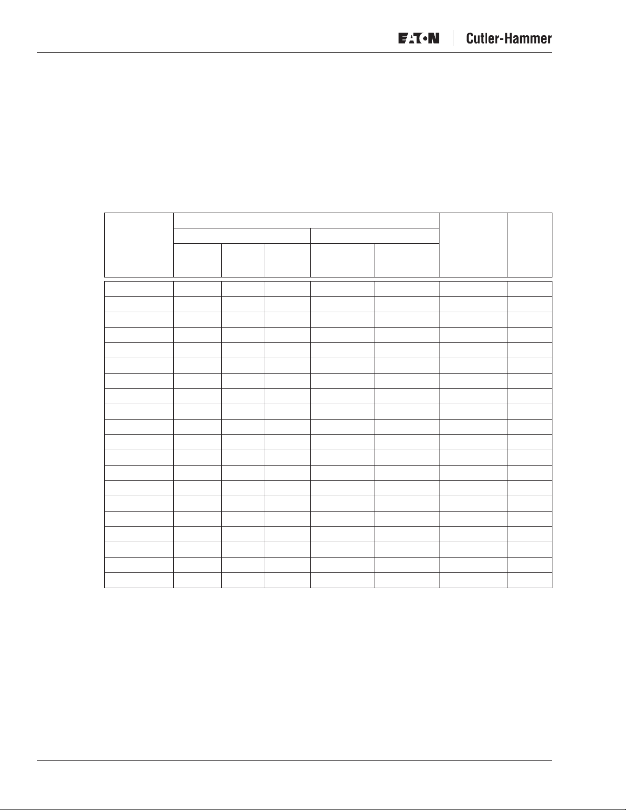
Table 2-1: One-Module Drive Dimensions (Mounting Base Included)
Approximate Dimensions in Inches (mm)
Chassis
CH3 6.30 (160) 16.97 (431) 9.69 (246) 66 (30)
CH4 7.60 (193) 19.41 (493) 10.12 (257) 77 (35)
CH5 9.69 (246) 21.77 (553) 10.39 (264) 88 (40)
CH61/62 9.69 (246) 25.91 (658) 14.65 (372) 121 (55)
CH72 9.69 (246) 42.36 (1076) 14.65 (372) 198 (90)
Te rm inals
Weight
in Lbs. (kg)Width Height Depth
January 2007
9.69
(246)
Water In/Out
7.64
(194)
16.97
(431)
2.20
(56)
3.98
(101)
2.32
(59)
6.30
(160)
3.23
(82)
Dia. .35
(9)
.47
(12)
1.57
(40)
.51
(13)
1.18
(30)
Figure 2-2: LCX9000 Liquid-Cooled Drive, CH3
Approximate Dimensions in Inches (mm)
Dia. .39
(10)
.59
(15)
3.19
(81)
1.57
(40)
2.32
(59)
2-2 For more information visit: www.EatonElectrical.com
MN04005001E

January 2007
LCX9000 Liquid-Cooled Drives User Manual
7.60
(193)
1.18
(30)
Dia. .39
(10)
7.48
(190)
2.72
(69)
3.35
(85)
(12)
Bottom View
Water In/Out
.65
(16.5)
2.36
(60)
4.09
(104)
Bottom
.47
.98
(25)
19.41
(493)
Dia. .39
3.03
(10)
(77)
Top View
6.57
(167)
.43
(11)
1.77
(45)
5.24
(133)
M8
.63
(16)
1.02
(26)
Dia. .35
(9)
Figure 2-3: LCX9000 Liquid-Cooled Drive, CH4
Approximate Dimensions in Inches (mm)
M12
.16
(4)
.26
(6.5)
.39
(10)
.49
(12.5)
.98
(25)
Dia. .51
(13)
10.12
(257)
2.60
(66)
M8
Dia. .51
(122)
2.24
(57)
2.24
(57)
2.48
(63)
(13)
4.80
6.97
(177)
10.39
(264)
MN04005001E
Top
3.15
(80)
.16
(4)
9.69
(246)
3.94
(100)
19.88
(505)
21.77
(553)
7.87
(200)
1.30
(33)
Figure 2-4: LCX9000 Liquid-Cooled Drive, CH5
Approximate Dimensions in Inches (mm)
For more information visit: www.EatonElectrical.com 2-3
LCX9000 Liquid-Cooled Drives User Manual
January 2007
3.19
(81)
6.85
(174)
1.77
(45)
9.69
(246)
Bottom
14.69
(373)
1.38
(35)
.39
(10)
3.94
(100)
3.15
(80)
5.91
(150)
.39
(10)
M12
Coolant
Outlet
UVW
Coolant
Inlet
x = Grounding Bolt
M8x25
Dia. .51
(13)
23.23
(590)
2.09
(53)
Figure 2-5: LCX9000 Liquid-Cooled Drive, CH61
Approximate Dimensions in Inches (mm)
Dia. .55
(14)
x
2.01
(51)
25.91
(658)
4.06
(103)
1.57
(40)
L3 L2 L1
2.56
2.56
(65)
(65)
9.21
(234)
Left SideFrontRight SideTop
1.30
(33)
23.07
(586)
.63
(16)
Top V i ew
6-Pulse Supply
1.57
(40)
12-Pulse Supply
.39
(10)
3.15
(80)
.39
(10)
.39
(10)
14.65
(372)
7.87
(200)
1.57
(40)
2.56
(65)
2.56
(65)
4.06
(103)
.87
1.57
(40)
.39
(10)
(22)
41.73
(1060)
36.65
(931)
39.37
(1000)
42.40
(1077)
2.95
(75)
.79
(20)
1.18
(30)
Dia. .51
(13)
Figure 2-6: LCX9000 Liquid-Cooled Drive, CH72
Approximate Dimensions in Inches (mm)
.55
(14)
1.30
(33)
2.66
(67.5)
.79
(20)
R .28
(7)
2.56
(65)
2.56
(65)
4.06
(103)
Coolant In/Out
Bottom
Dia. .55
(14)
9.21
(234)
2.01
(51)
2-4 For more information visit: www.EatonElectrical.com
MN04005001E

January 2007
LCX9000 Liquid-Cooled Drives User Manual
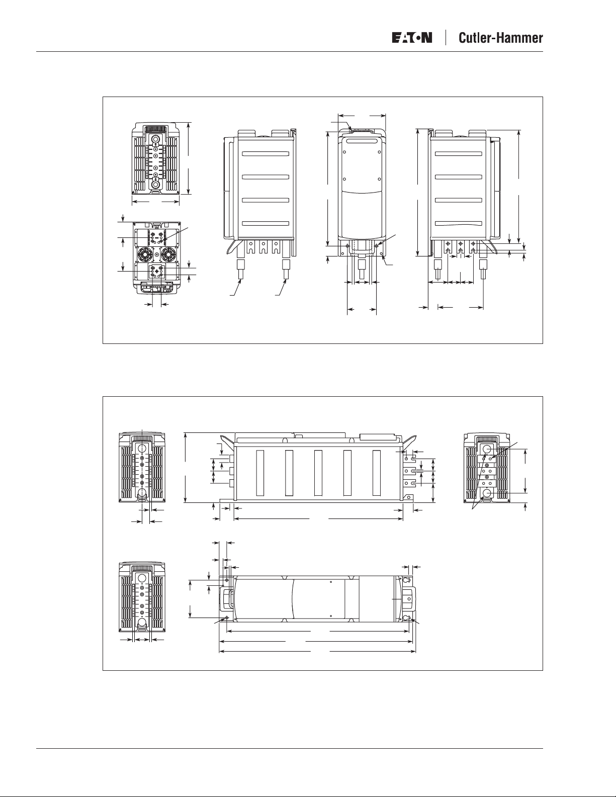
Drives Consisting of Several Modules
Liquid-cooled drives consisting of several modules are mounted in a mounting bracket as
presented in Figure 2-7.
Figure 2-7: Drive Mounted Inside Mounting Bracket
Table 2-2: Several Module Drive Dimensions (Mounting Bracket Included)
Approximate Dimensions in Inches (mm)
Chassis
CH63 19.88 (505) 36.38 (924) 14.76 (375) 264 (120)
CH64 29.37 (746) 36.38 (924) 14.76 (375) 396 (180)
CH74 29.37 (746) 46.26 (1175) 15.16 (385) 617 (280)
Weight
in Lbs. (kg)Width Height Depth
MN04005001E
For more information visit: www.EatonElectrical.com 2-5

LCX9000 Liquid-Cooled Drives User Manual
.98
(25)
Dia. .43
(11)
2.36
(60)
Bottom Top
18.90
(480)
9.69
(246)
.39
(10)
1.18
(30)
9.21
(234)
1.77
(45)
January 2007
Dia. .55
(14)
.98
(25)
.87
(22)
Coolant
Outlet
1.97
(50)
6.85
(174)
4.53
(115)
.39
(10)
3.27
(83)
1.57
(40)
4.69
(119)
6.42
(163)
34.25
(870)
Dia. .43
Coolant
Inlet
Dia. .55
(14)
1.34
(34)
(11)
.24
(6)
3.94
(100)
4.06
(103)
2.95
(75)
19.88
(505)
3.94
(100)
3.94
(100)
2.09
(53)
(100)
13.98
(355)
3.94
3.94
(100)
3.94
(100)
.20
(5)
34.41
(874)
36.38
(924)
(224)
1.30
(33)
(16.5)8.82
1.20
(30.5)
.59
(15)
.65
.55
(14)
(105)
4.13
Dia. .98
(25)
2.56
(65)
14.76
(375)
Left SideRight Side Front
2.56
(65)
1.57
(40)
23.94
(608)
23.58
(599)
11.50
(292)
Figure 2-8: LCX9000 Liquid-Cooled Drive with Mounting Bracket, CH63
Approximate Dimensions in Inches (mm)
2-6 For more information visit: www.EatonElectrical.com
MN04005001E

January 2007
LCX9000 Liquid-Cooled Drives User Manual
28.39
(721)
.59
(15)
Bottom
5.79
(147)
1.38
(35)
1.18
(30)
Dia. .43
(11)
Dia. .55
(14)
15.16
(385)
.67
(17)
(105)
6.89
(175)
6.89
(175)
6.89
(175)
6.89
(175)
1.57
(40)
2.56
(65)
4.13
(10)
.47
(12)
.47
(12)
.39
(12)
.63
(16)
.47
.47
(12)
.55
(14)
(33)
2.87
(73)
1.3
2.99
(76)
43.31
(1100)
46.26
(1175)
29.29
(744)
3.46
(88)
3.15
(80)
.39
(10)
.98
(25)
Dia. .18
5.51
(140)
(4.6)
14.72
6.69
(170)
7.87
(200)
7.87
(200)
7.87
(200)
(374)
9.69
(246)
9.69
(246)
3.15
(80)
1.57
(40)
.39
(10)
.39
(10)
.39
(10)
Top
6-Pulse Supply
12-Pulse Supply
29.37
(746)
29.37
(746)
Figure 2-9: LCX9000 Liquid-Cooled Drive, CH74, IP00
Approximate Dimensions in Inches (mm)
MN04005001E
For more information visit: www.EatonElectrical.com 2-7

LCX9000 Liquid-Cooled Drives User Manual
Cooling
Instead of using air for cooling, Cutler-Hammer Liquid-Cooled drives are cooled with liquid.
The liquid circulation of the drive is usually connected to a heat-exchanger (liquid-liquid/
liquid-air) which cools down the liquid circulating in the cooling elements of the drive. The
cooling agents acceptable for use are drinking water, demineralized water or a mixture
(60/40) of water and glycol. In a closed circulation system, the values in Table 2-3 are
recommended reference values. To avoid electrochemical corrosion, Eaton recommends
adding an inhibitor (e.g. Ferrolix 332/Henkel or Cortec VpCI-649) in the cooling agent.
Note:
If no heat-exchanger is used, actions must be taken to avoid electrochemical corrosion.
Specifically no brass or copper elements may be used in the liquid circulation of the drive.
Drinking Water Specification
Table 2-3 provides general guidelines for water quality.
Note: 1 mg/L = 1 ppm.
Table 2-3: Drinking Water Chemical Specification
Quality Unit Value Quality Unit Value
Acrylamide µg/L 0.10 Mercury µg/L 1.0
Antimony µg/L 5.0 Nickel µg/L 20
Arsenic µg/L 10 Nitrate [NO
Benzene µg/L 1.0 Nitrate-Nitrogen [NO
Benzopyrene µg/L 0.010 Nitrite [NO
Boron mg/L 1.0 Nitrite-Nitrogen [NO
Bromate µg/L 10 Bactericides µg/L 0.10
Cadmium µg/L 5.0 Bactericides, total µg/L 0.50
Chromium µg/L 50 Polynuclear aromatic
Copper mg/L 2.0 Selenium µg/L 10
Cyanides µg/L 50 Tetrachloroethylene and
1,2-Dichloroethane µg/L 3.0 Trihalomethanes total µg/L 100
Epichlorohydrin µg/L 0.10 Vinyl chloride µg/L 0.50
Fluoride mg/L 1.5 Chlorophenols total µg/L 10
Lead µg/L 10
]mg/L50
3
]mg/L0.5
2
hydrocarbons
trichloroethylene total
January 2007
-N] mg/L 11.0
3
-N] mg/L 0.15
2
µg/L 0.10
µg/L 10
Table 2-4: Drinking Water Quality
Recommendations — Maximum Values
Quality Unit
Aluminum µg/L 200
Ammonium [NH
Ammonium [NH
Chloride
]mg/L0.50
2
-N] mg/L 0.40
2
mg/L <100
Manganese µg/L 50
Iron µg/L <0.5
Sulphate
mg/L 250
Sodium mg/L 200
Oxidizability [COD
No aggressive water allowed.
To avoid corrosion of piping, the sulphate content must not
exceed 150 mg/L.
]mg/L 5.0
Mn-O2
Max.
Val ue
2-8 For more information visit: www.EatonElectrical.com
MN04005001E