

Page 1
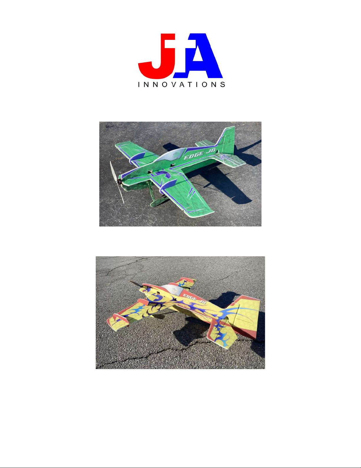
JTA Innovations 33” Edge JD
Page 2

Please Read For Your Safety
The product that you have received is not a toy. Please understand that model
aircraft have several moving parts and equipment that if misused, can not only
cause harm to other materials and objects, but also to you and others around
you. JTA Innovations is not accountable or responsible for any events or
incidents that cause damage, injury, or even death. After purchase and
receiving of this product, the customer is fully responsible for the assembly
and use of the model. We cannot monitor the procedure/methods used in
assembling or flying of the model. If operating in the United States, please
make sure that you have membership with the Academy of Model Aeronautics
and follow AMA rules. Please operate the model at AMA flying sites. If living
outside of the US, please follow the rules of model aviation operation in your
region. JTA Innovations is not responsible for any disregard or breaking of
these rules. Prior to being shipped to each customer, airframes will be checked
for any damages. We have no control over what happens during the shipping
process. If any product is deemed defective by a customer, please contact JTA
Innovations with proof of defect (most likely photo or video), and proof of
purchase including purchase date. JTA Innovations will analyze your claim and
handle the situation case by case.
Page 3

Tools/Supplies needed
Including but not limited to:
-Ruler
-Building Adhesive
-Foam safe CA or and regular CA
-Hobbyknife with blades
-Scissors
-Heat gun or lighter for heat shrink
-Assorted phillips and flat blade screwdrivers
-Assortment of small drill bits
-Drill
-Needle nose pliers
-Driver set
-90 degree square
-CA accelerator
-Sandpaper
- Wax Paper for a building surface
Page 4

Airframe Description
Welcoming in the 4th year of JTA Innovations, the 33” Edge JD is a perfect
representation of how we have reached the pinnacle of aerobatic flat
foamies with both it’s flying characteristics and presentation. The Edge JD
offers every forgiving 3D characteristic that you could expect from an Edge
along with the all around precise performance you’d expect from a JTA
Innovations airframe. The abundance of side area allows for excellent knife
edge and precision flight while keeping the aggressive possibilities that we
have all been accustomed to with JTA Innovations airframes. The Edge JD
will be sure to complement whichever type of aircraft lineup you have with
it’s unique blend of looks and flying characteristics. Additionally, the
standard JTA Innovations construction technique is included on the Edge
which will provide several demanding flights indoors or outdoors.
Wingspan- 33” (6mm EPP)
Weight- Approximately 185-200g
Motor- T-Motor AM40, or AT2303 or 2304 or equivalent
ESC- 10-15amp (T-Motor AT12A available at JTA) or 16amp ESC for AM40
Servos- 7g-12g (Spektrum A3030, MKS HV6100, EMax ES08, JR E397, etc.)
Prop- 8”-9” (8” for 3S setup, 9” for 2S setup)
Battery- 350-800mah 2S or 3S depending on motor/ESC combo max cell
capabilities
Page 5
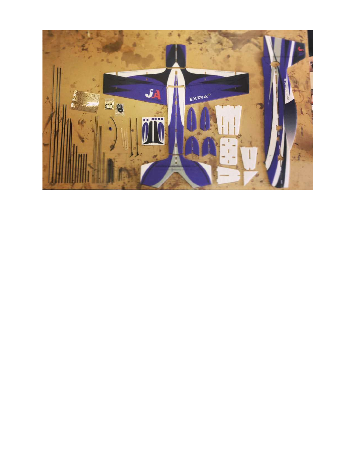
Kit contents shown above (Extra JD shown for representation)
Below are lengths of control surface linkages. Linkages are
used from the provided carbon fiber rods.
Aileron linkages: 65mm (x2)
Elevator linkage: 365mm (x1)
Rudder linkage: 365mm (x1)
Page 6
Page 7
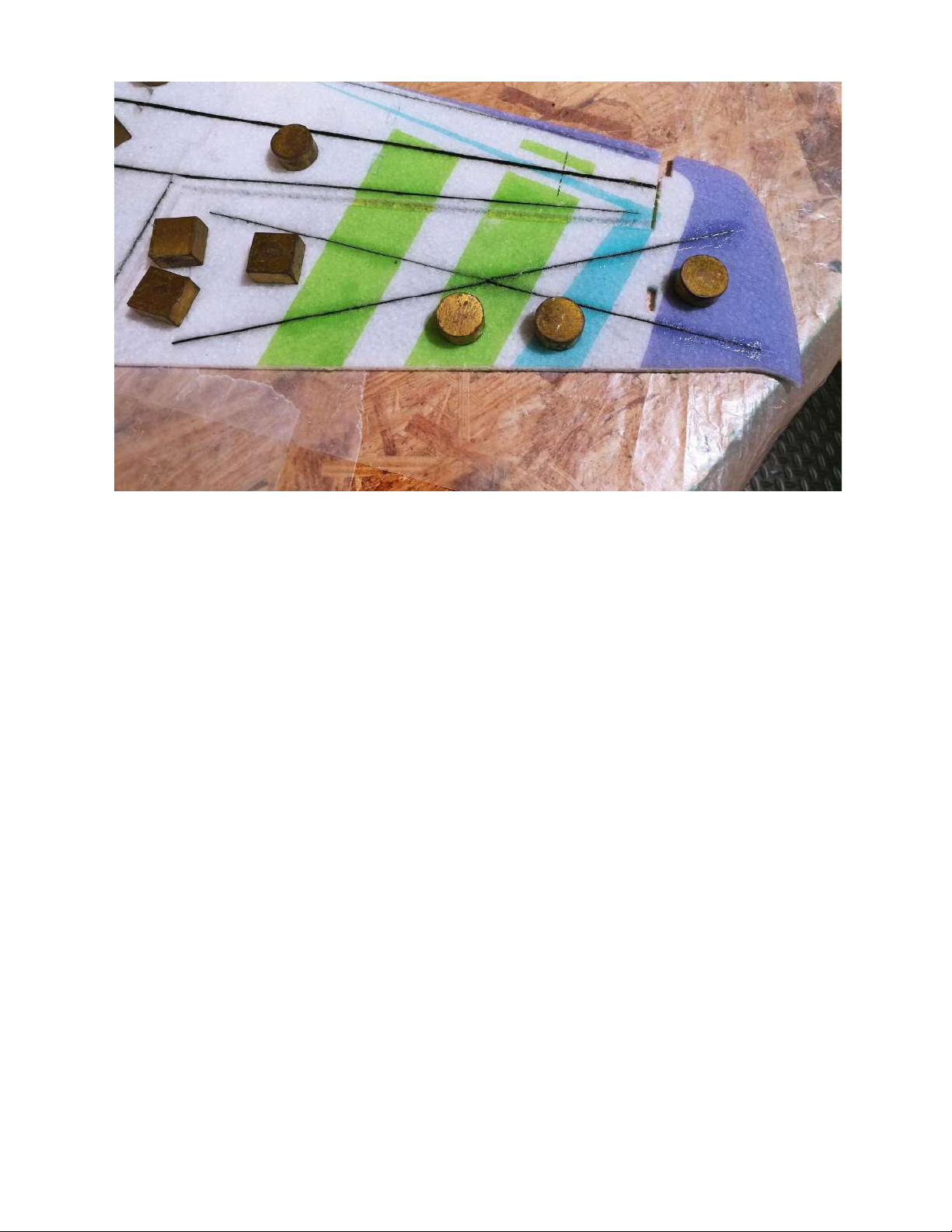
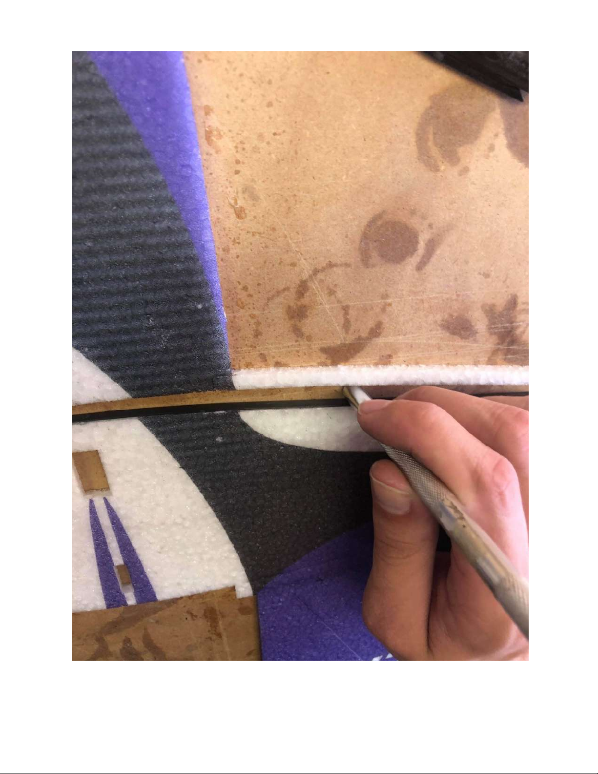
As shown above, the aileron bracing is done using flat
carbon fiber glued into the slots creating durability for the
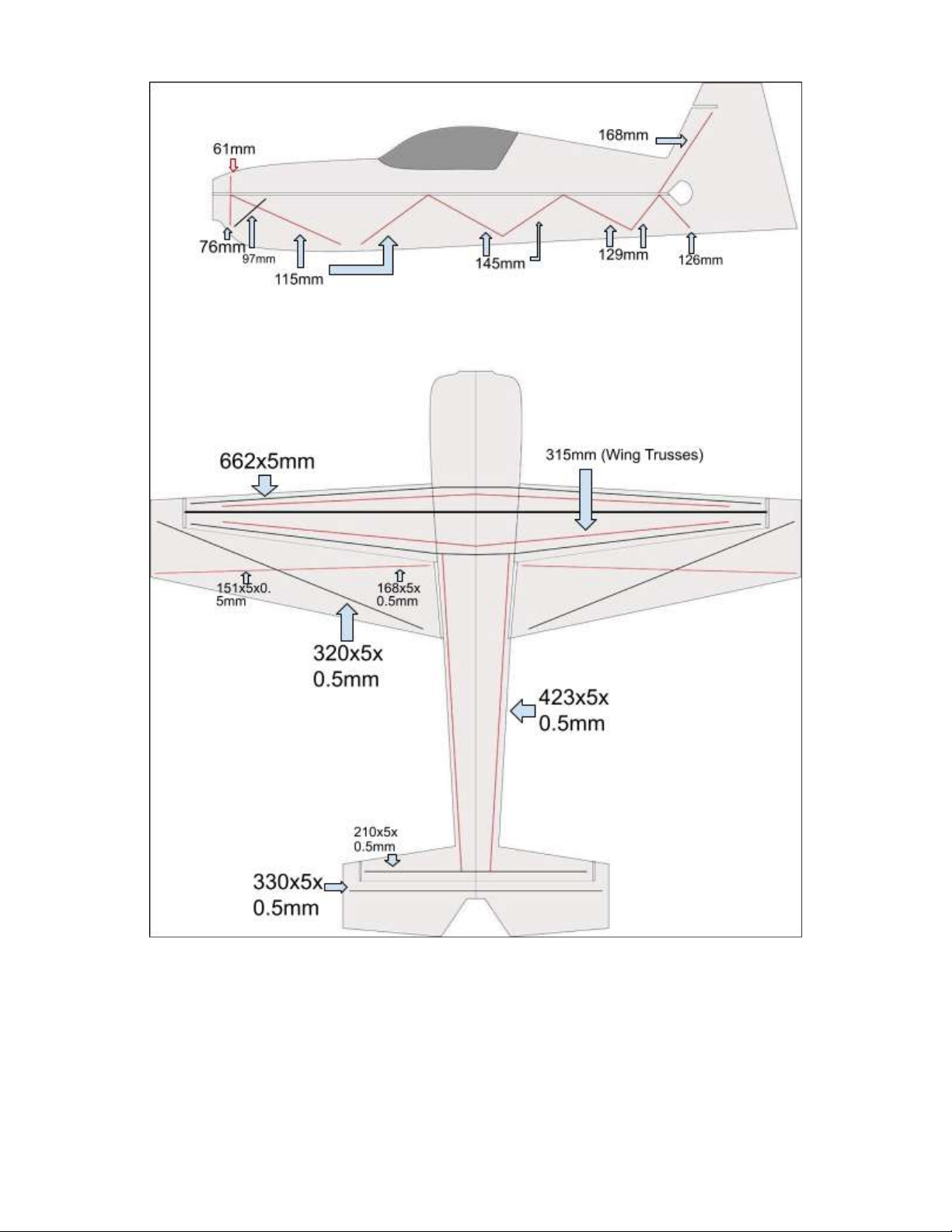
aileron. Please see the carbon fiber diagram for your
airframe to determine which size carbon strips are to be
used.
Page 8
Page 9
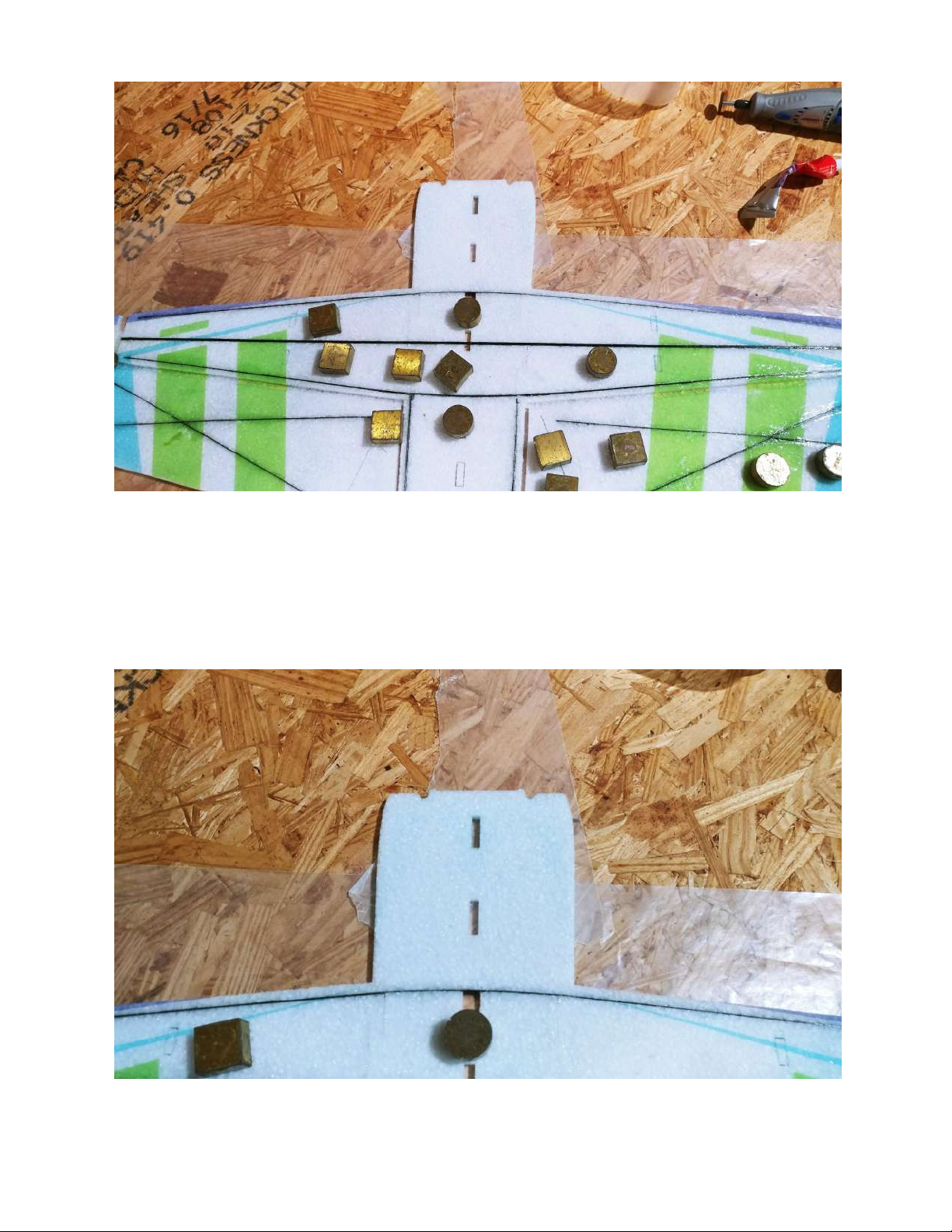
Wing bracing shown above. The center wing spar is the
supplied carbon fiber square stock.
Cowl glued to the fuselage.
Page 10
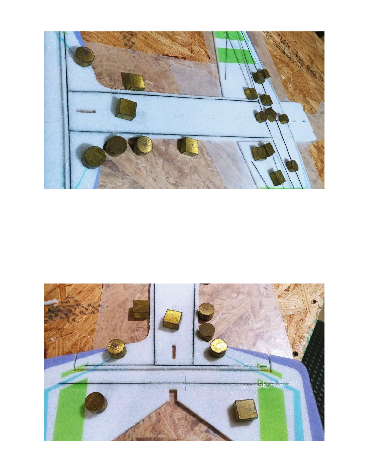
The horizontal piece of the fuselage also uses flat carbon
fiber spanning the entire length from the rear wing spar to
the horizontal stab spar.
Page 11
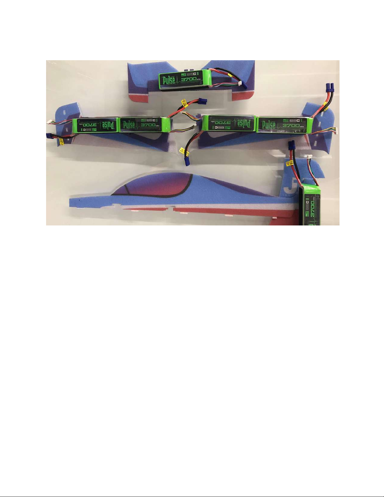
Elevator flat spar and h-stab flat spar shown above.
Now that rigidity is established, it is very important to break
in the hinges by flexing them all the way over and weighing
them down. Let them rest for at least 60 minutes.
Page 12
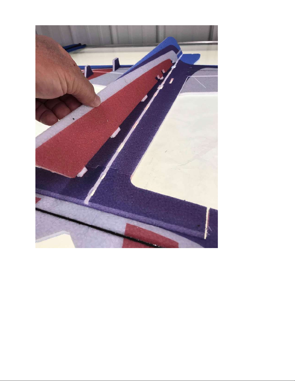
You can now prepare the bottom half of the fuselage. Test fit this into each slot
as shown above before gluing.
Page 13
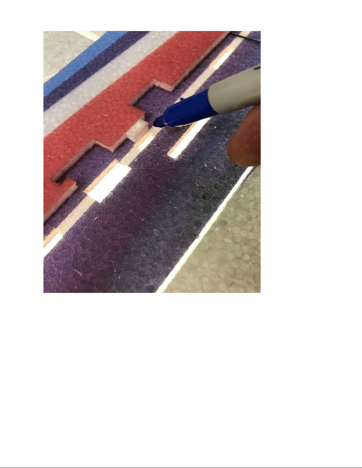
If deciding to place glue on the horizontal part of the fuselage, you can mark
out where the glue will be placed as shown above after test fitting the fuselage.
Page 14
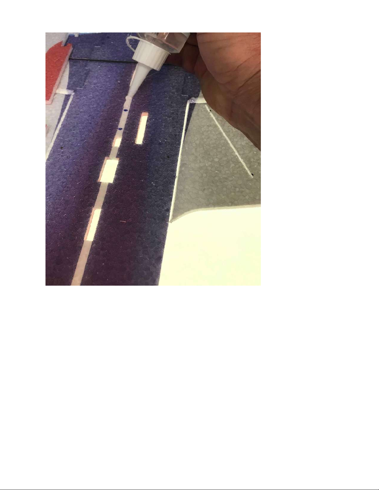
Using the marks that you just made, place your glue along the fuselage.
Page 15
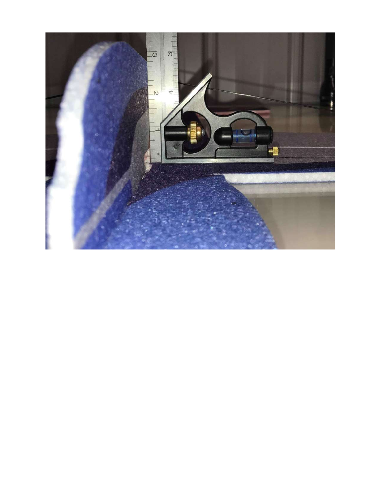
It is extremely important to make sure that the bottom vertical part of the
fuselage stays 90 degrees to the horizontal fuselage while the glue is setting.
This can have a huge effect on the flying characteristics.
Page 16
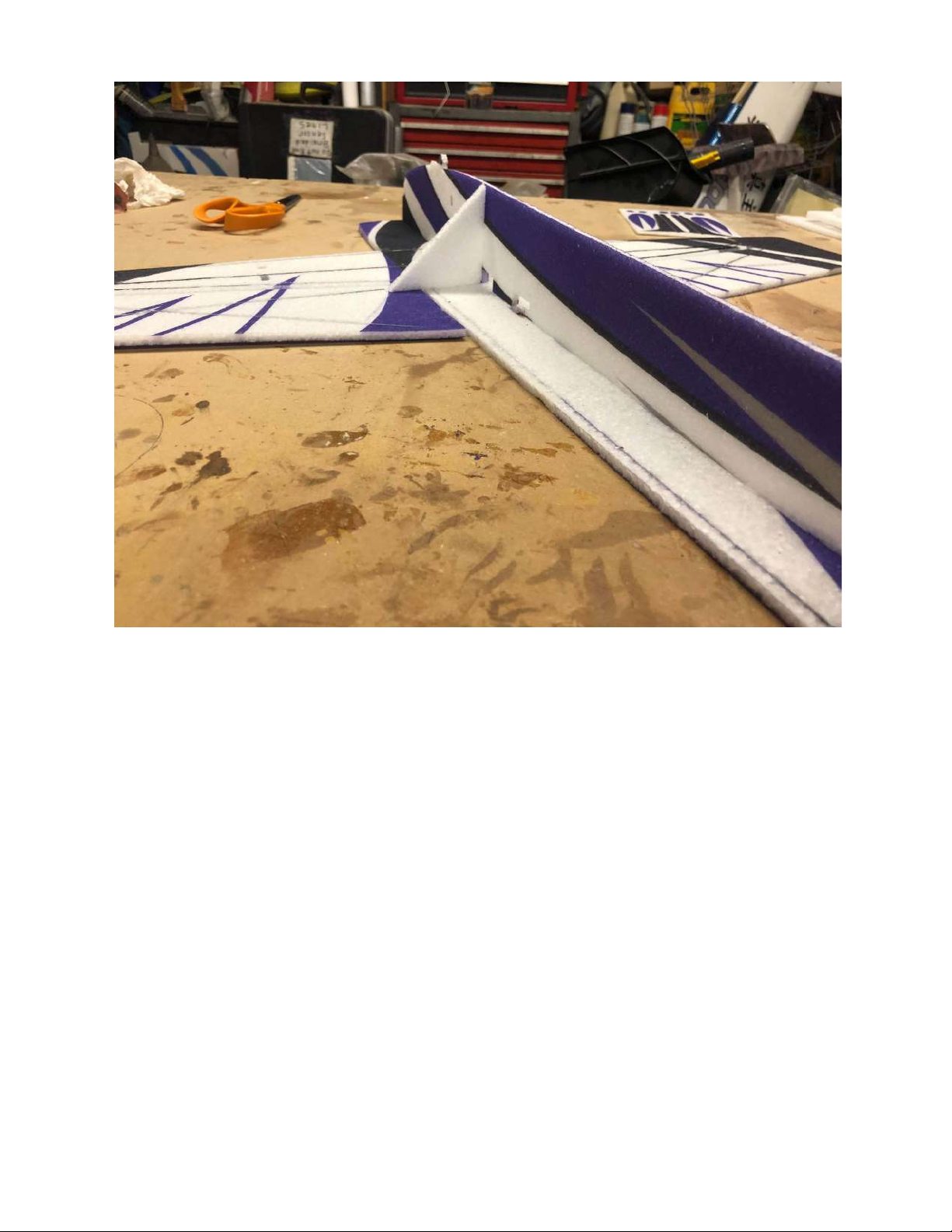
The provided EPP square may be useful during this process of gluing the
bottom fuselage piece.
Page 17
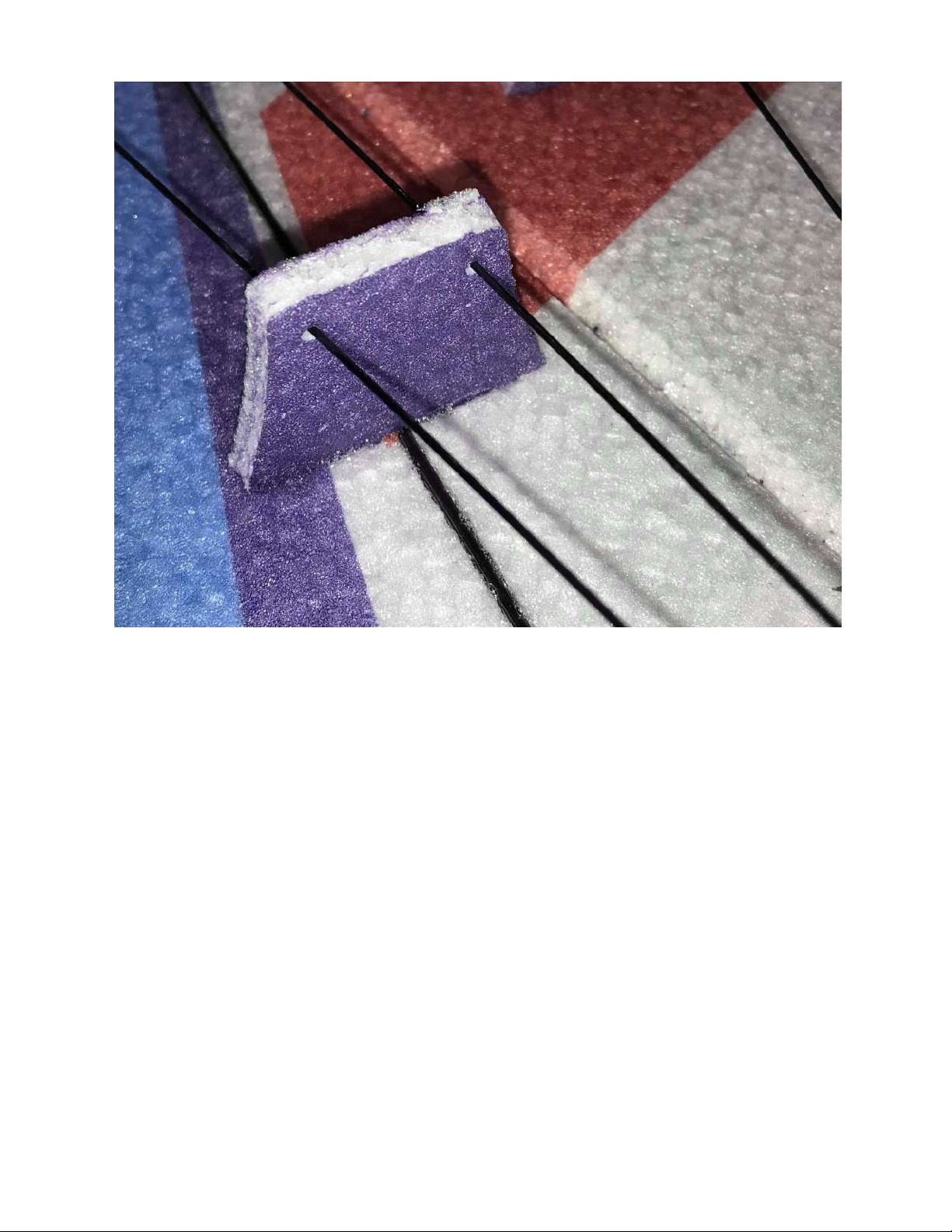
Now that the bottom fuselage piece is glued into place, you can locate the
carbon fiber rods used for the wing bracing. Shown above is the wing joiner
used to guide the wing bracing. Some airframes may have a larger gusset or
joiner that overlaps the leading edge. You will also find dots towards the tip of
each wing to determine where to glue the carbon rods. The same goes for the
location on the bottom part of the fuselage. There should be four total carbon
rods for wing bracing. Two will be used on each wing. Lengths can be found
Page 18

on the carbon fiber diagram.
Above is a photo of what your gusset may look like depending on your
airframe. Also some of the completed carbon fiber rod construction is shown
above.
Page 19
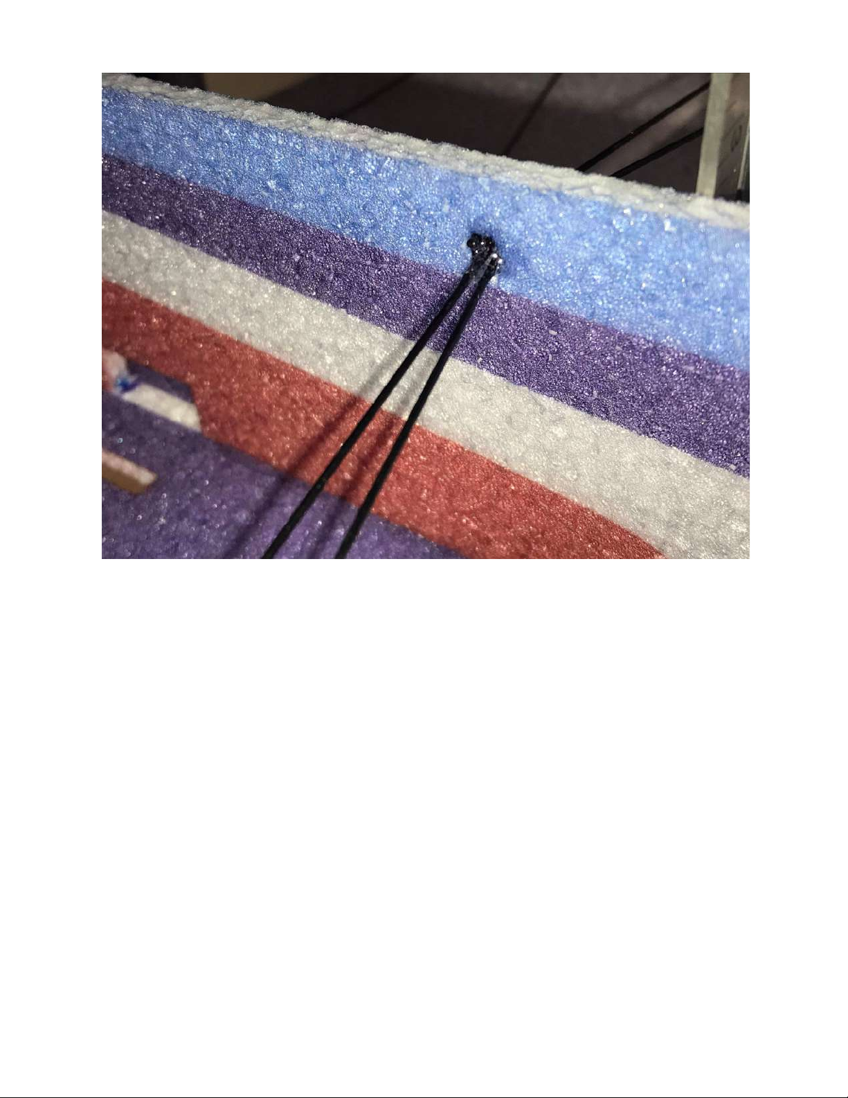
Shown above is the wing bracing glued into the bottom part of the fuselage.
Page 20
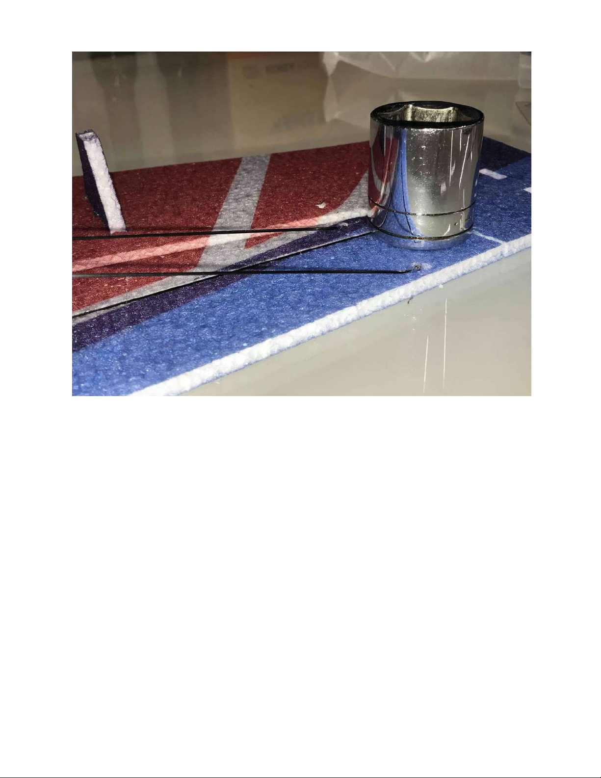
Just like the aileron bracing, it is very important to use weight towards the
wing tip while the carbon wing bracing is set up to keep the leading edge of
the wing as straight as possible.
Shown above is one of the carbon fiber landing gear legs that come pre-glued
Page 21
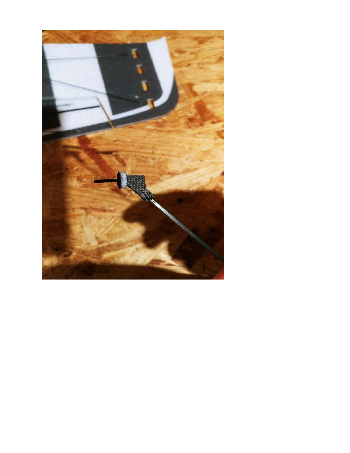
to the axle. The larger of the two EPP foam circular collars will slide on first.
No need to apply glue to anything quite yet.
Page 22
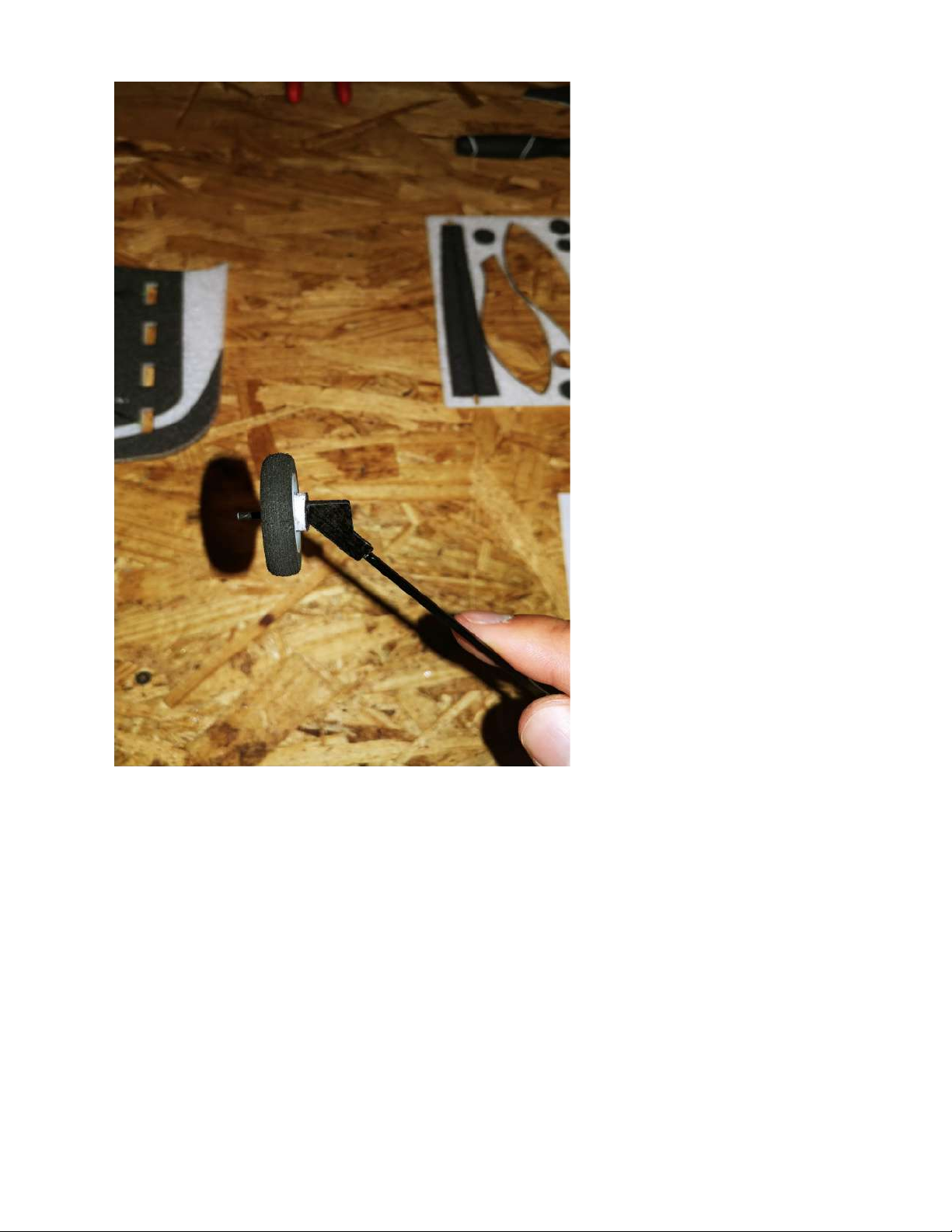
Next, with no glue needed, slide one of the wheels on to the axle all the way up
to the first foam collar. Make sure it is spinning freely.
Page 23
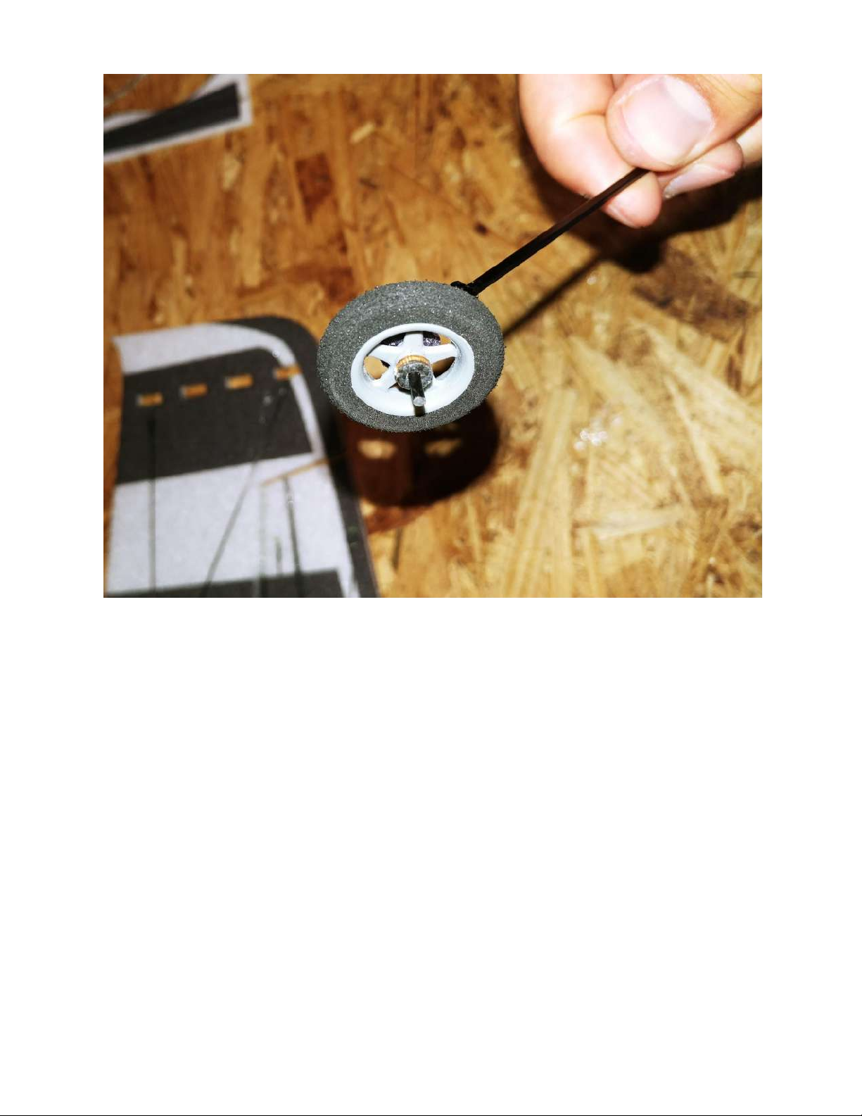
Now locate the plywood/carbon fiber laminated collar to slide up next to the
plastic wheel. Once again, do not apply glue yet as the tire will need to spin as
freely as possible around the axle.
Page 24
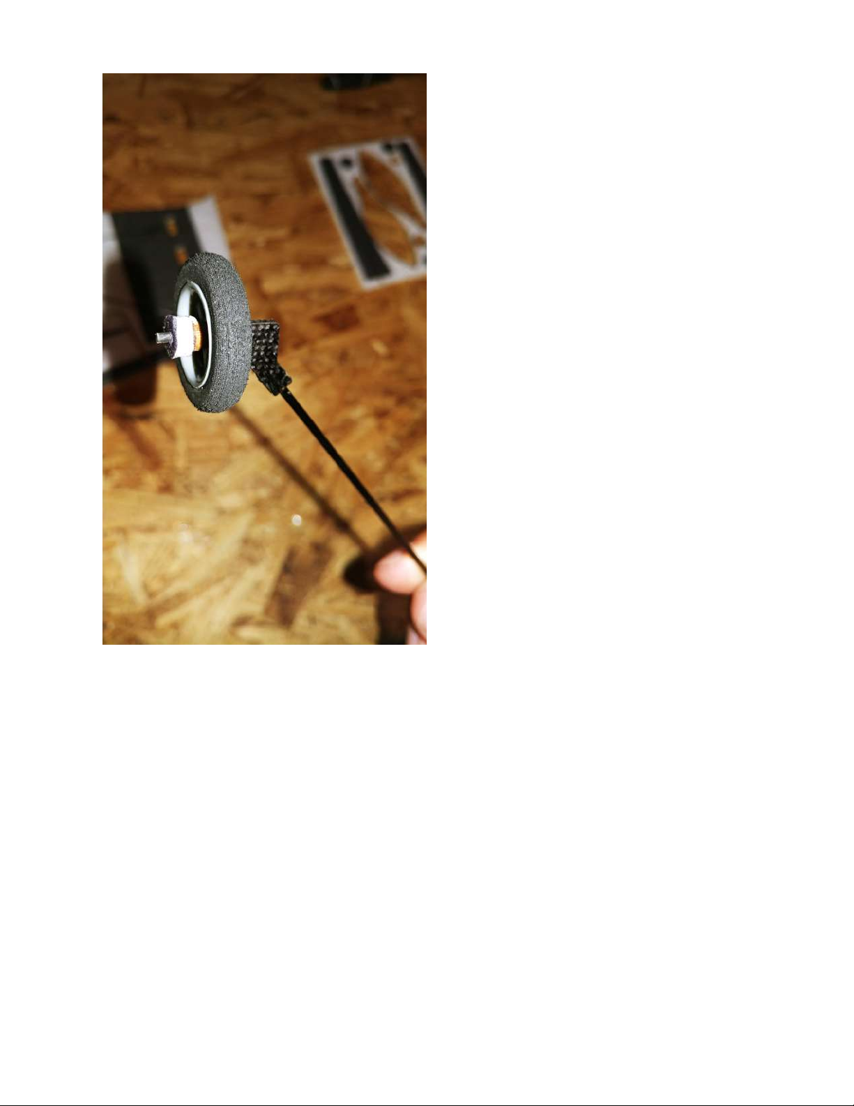
Locate the smaller of the two circular foam collars to slide onto the axle next.
Page 25
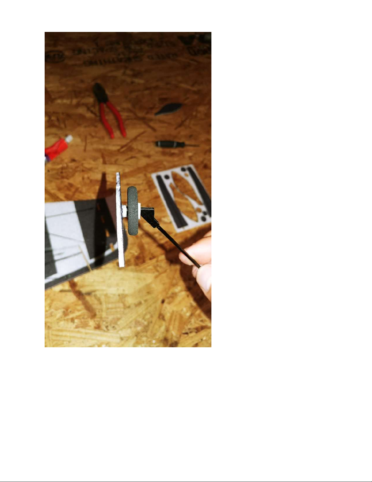
Lastly, locate one of the wheel pants. You can place a bit of adhesive on the
last foam collar before sliding the wheel pant on to the axle. If desired, you can
place some adhesive on the outside of the wheel pant where the carbon fiber
axle ends.
Page 26
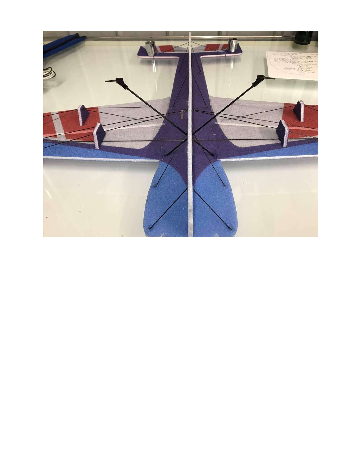
Shown above are both landing gear legs in place. You will find the slots cut in
the side of the bottom of the fuselage to slide each landing gear leg into. Make
sure that the bottom of each leg is placed to where the airplane will sit level on
the ground. Also shown are the first two carbon braces on the front of each
side of the bottom of the fuselage.
Page 27
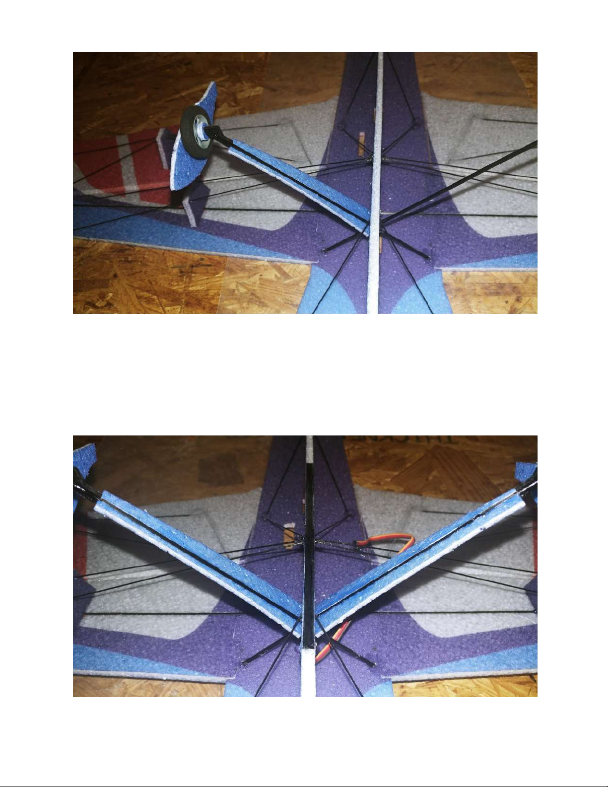
Locate the EPP landing gear cover that will be placed over the carbon fiber
landing gear leg. Test fit this piece, then glue it on over the carbon fiber using
the pre-cut slot.
Page 28
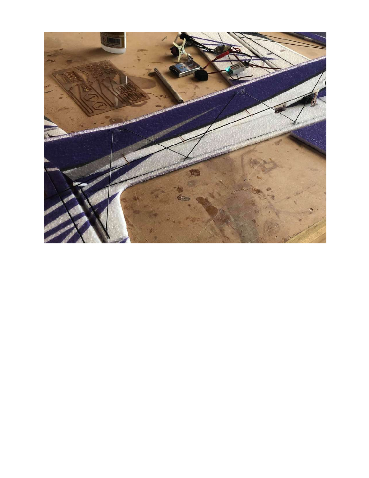
Shown above is the bottom fuse bracing for the rear of the fuselage. Lengths
found in diagram.
Page 29
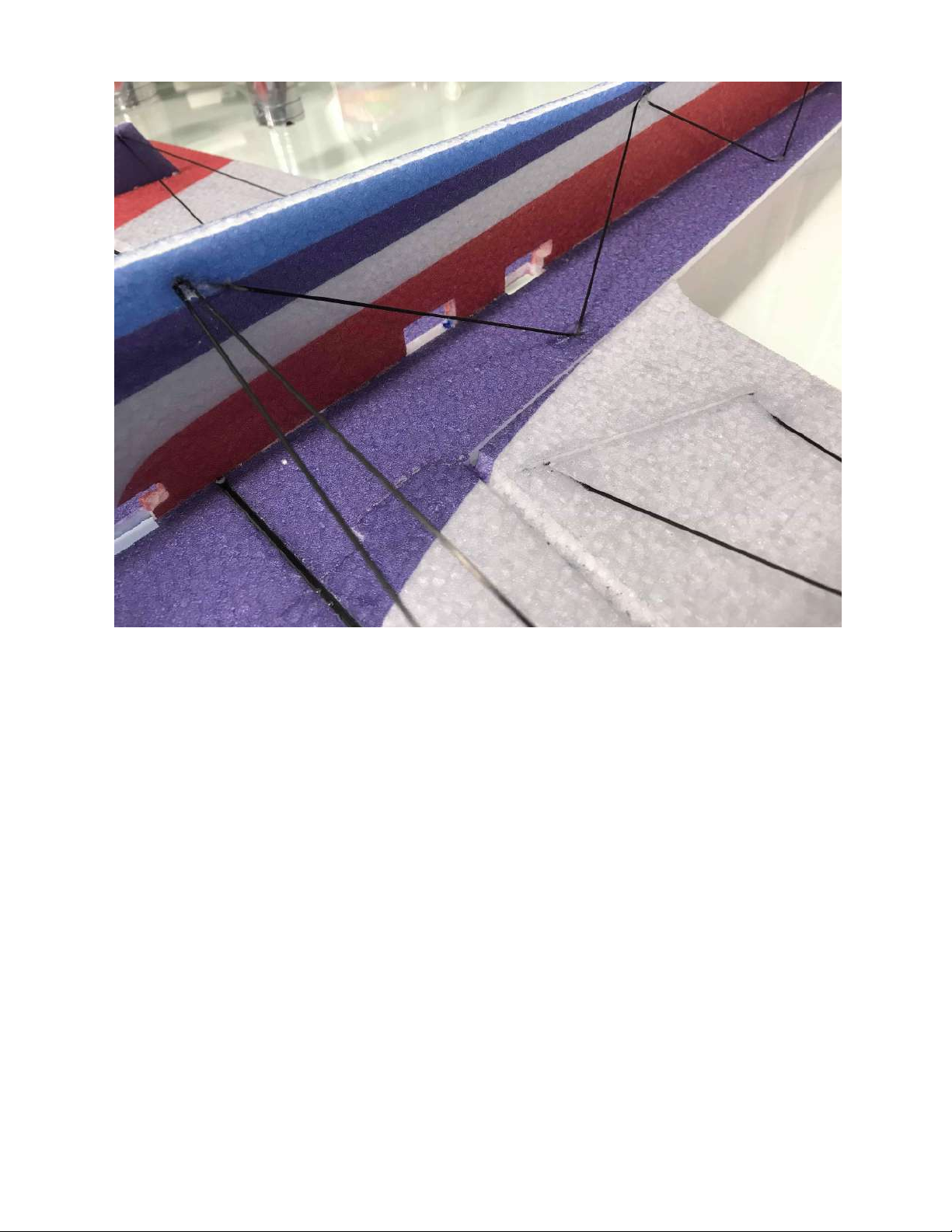
Shown above is the rest of the bottom fuselage bracing up to the wing bracing.
You should be able to notice the dots marked to help guide where each rod will
be placed. Lengths found in diagram.
Page 30
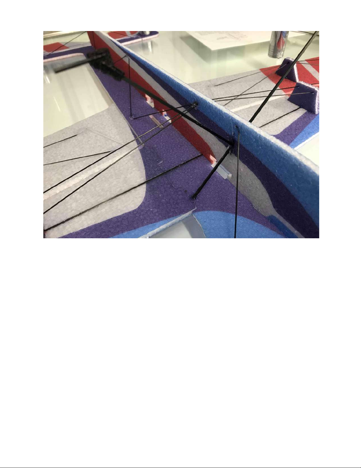
Above is the other side of the fuselage carbon fiber arrangement.
Page 31
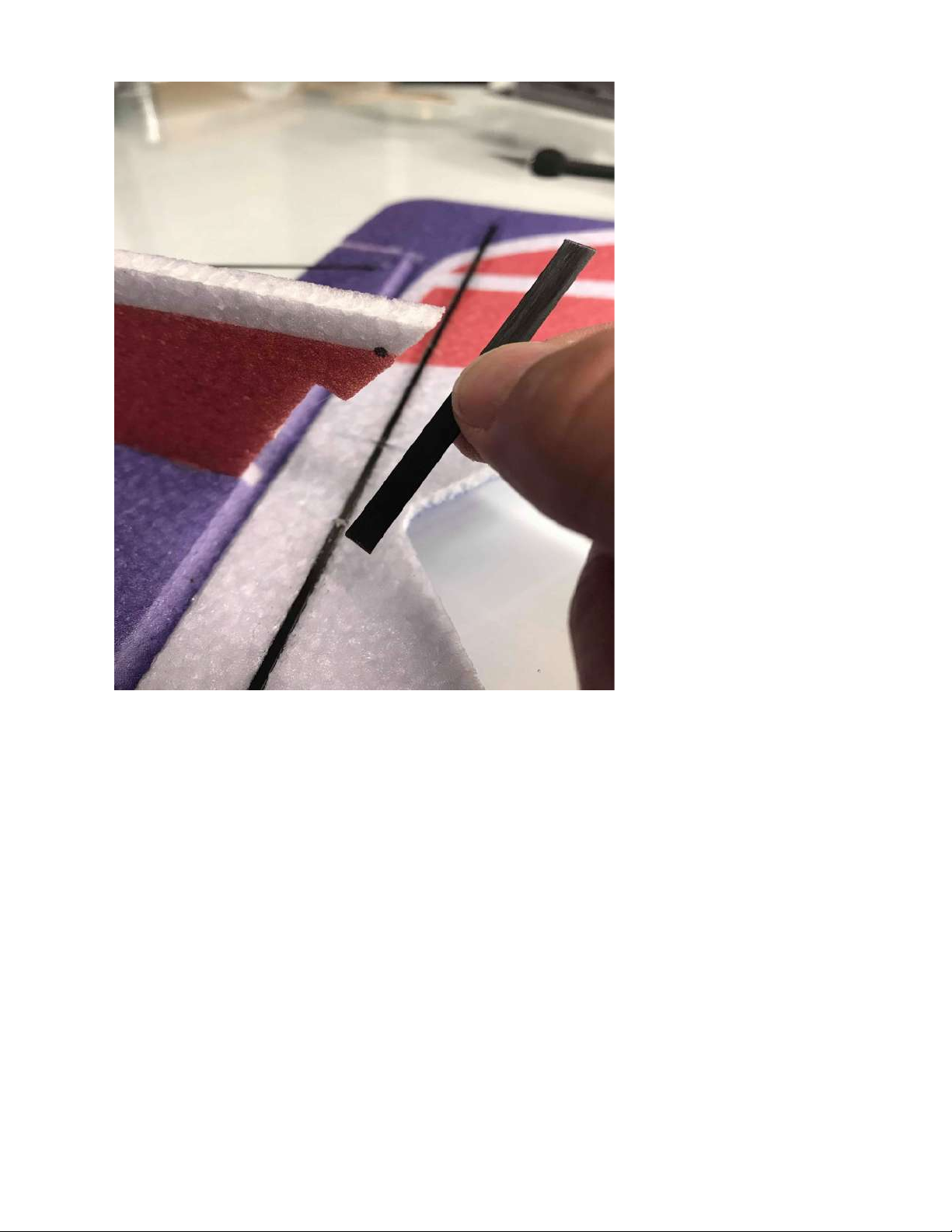
Locate the short flat carbon fiber piece that will be used as the tail piece for
taxiing, taking off, and landing.
Page 32
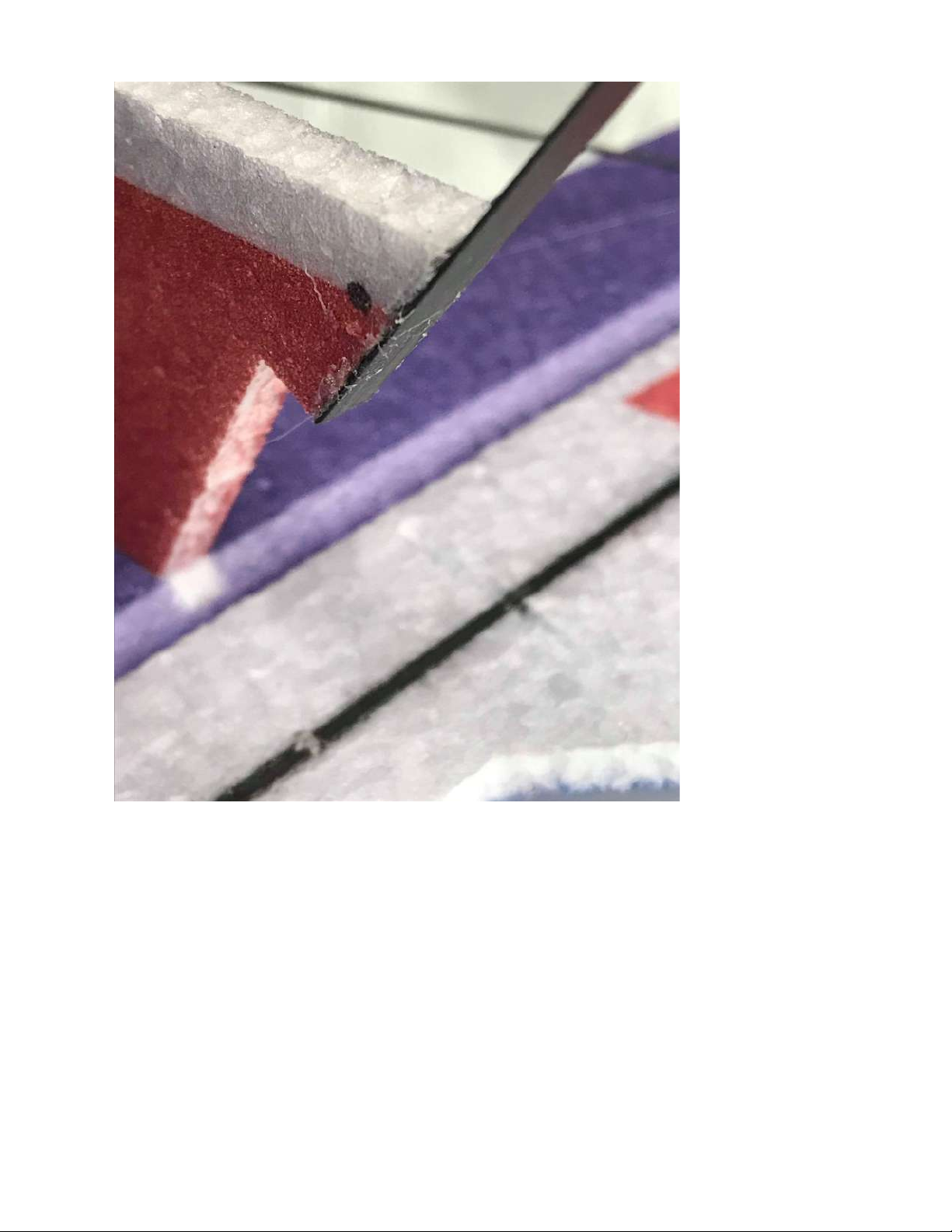
Glue the tailpiece into place as shown above while making sure that it is on the
same angle of the bottom of the fuselage to ensure that the airframe will sit
level.
Page 33
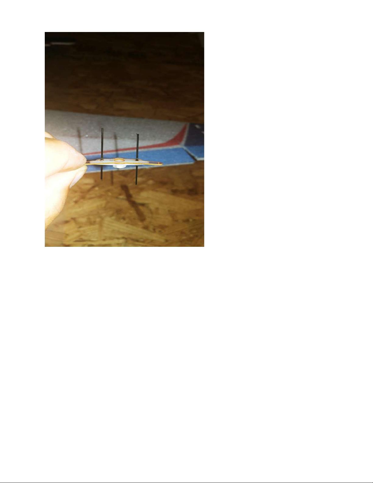
You can now prepare your servo arms. Above is the provided double arm to
be added on to the aileron servo arm that comes with the servo. Using the
extension will provide the maximum amount of aileron throw. To join the two
arms, use carbon fiber rods as shown above and glue them in through the
holes lined up on each arm. It is important to use regular CA for this. You can
then cut each rod down to shorten them.
Page 34
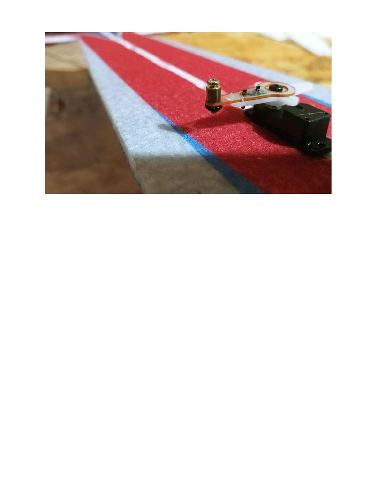
Before placing the servo arm on the servo, locate the mini EZ connector.
These connectors will be used to secure the linkage to the servo arm. Slide the
top metal piece into the end of the servo arm and then fasten the bottom
plastic piece through the pin. You may want to put a bit of CA on the bottom
of the pin and plastic piece to provide the most possible strength. The mini EZ
connector will allow you to center your surfaces mechanically to reduce the
need for subtrim. The top screw will be used to tighten down on the linkage
once the center is found.
Page 35
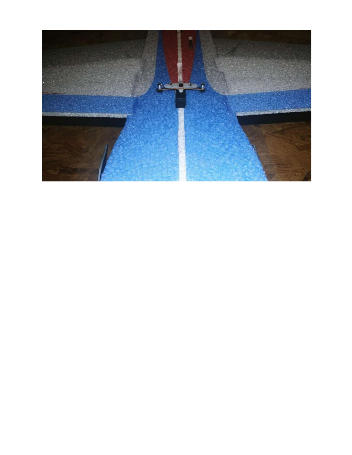
After you electronically center your aileron servo by plugging it into your
receiver and powering it on with zero sub trim and trim, you can glue it into
the servo slot that is the most forward on the airframe with the output shaft
facing rear. The aileron servo arm will be angled forward.
Page 36
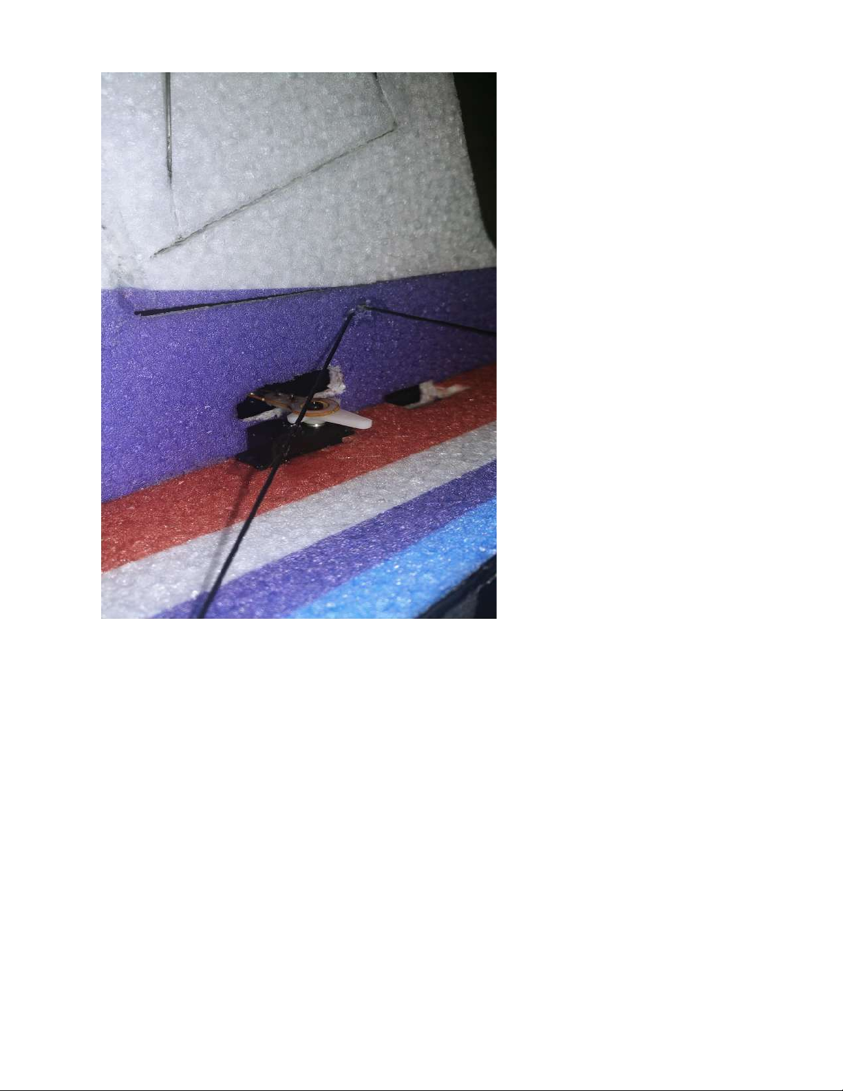
Shown above is the glued in elevator servo. For the elevator, use the middle
servo slot that is on the side of the fuselage. The arms used for the elevator
and rudder servos are the singles. For both the elevator and rudder servos,
face the output shaft towards the rear.
Page 37
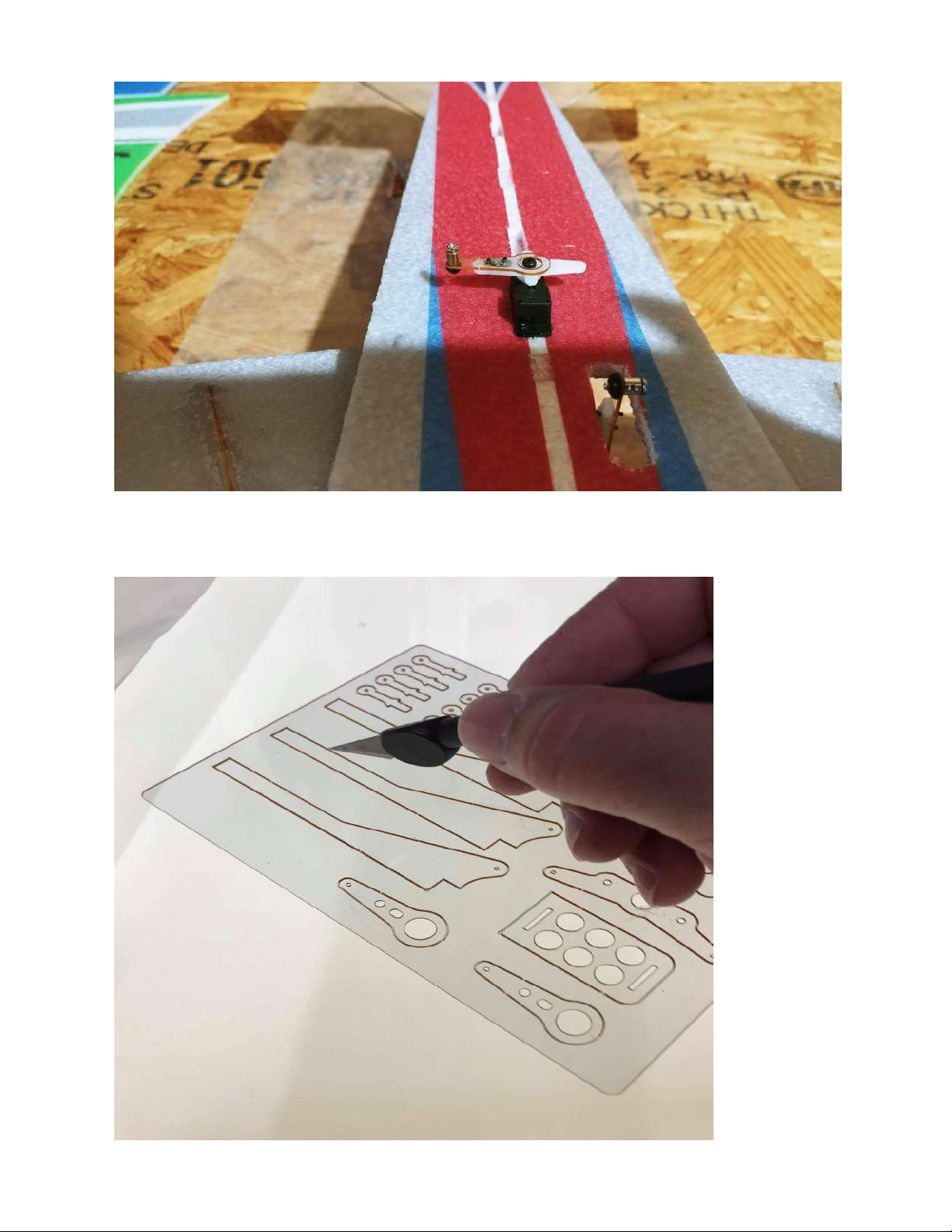
Shown above is the rudder servo mounted in the furthest rear servo slot.
Page 38
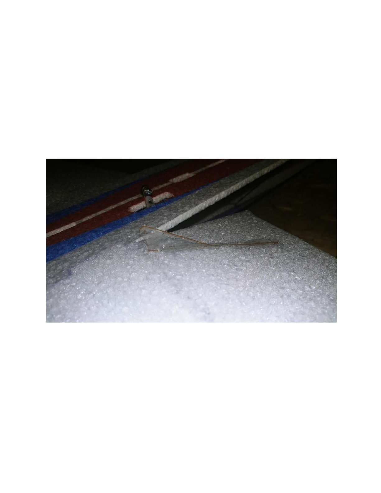
Locate the control horns in the provided kit. You will find three longer horns
and one shorter one. Two long ones will be used for the ailerons and one long
horn for the rudder. The shorter one will be used on the elevator. You will
notice a cutout on the bottom of the elevator horn that will fit over the
elevator spar.
Shown above is one of the aileron horns in place on the top of the aileron.
Page 39
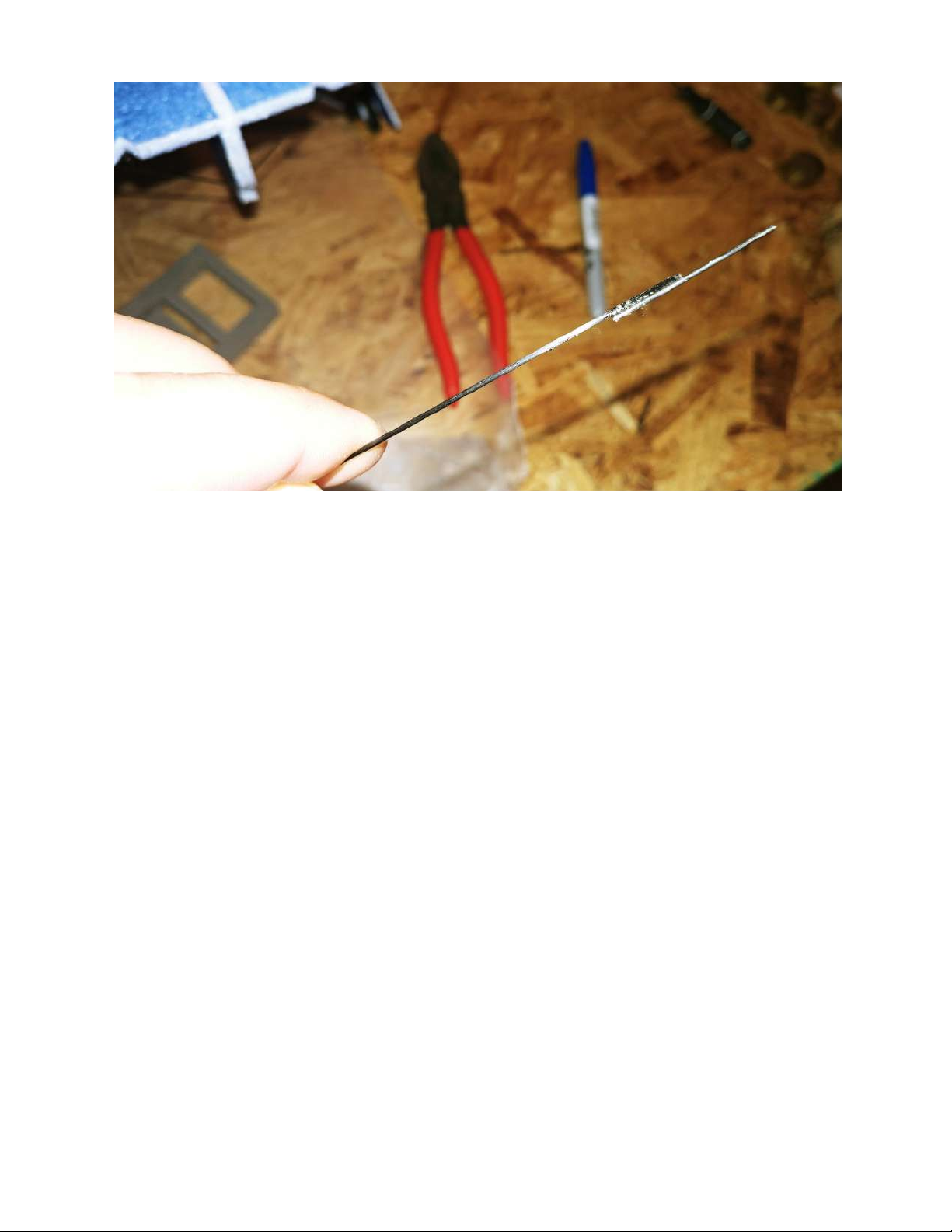
Locate the carbon fiber rods to be used for the aileron linkages (lengths shown
in diagram). This will be cut and used for the two aileron linkages. Also locate
the straight metal piece as shown above. Use regular CA to glue these two
together. The straight metal piece will be what slides into the mini EZ
connector on the servo arm of the aileron. The metal Z bend provided in the
kit will be glued to the opposite end of the linkage and fit into the control
horn. *Make sure to cut your heat shrink and place it on to the linkage before
glueing the Z bend and straight end.*
Page 40
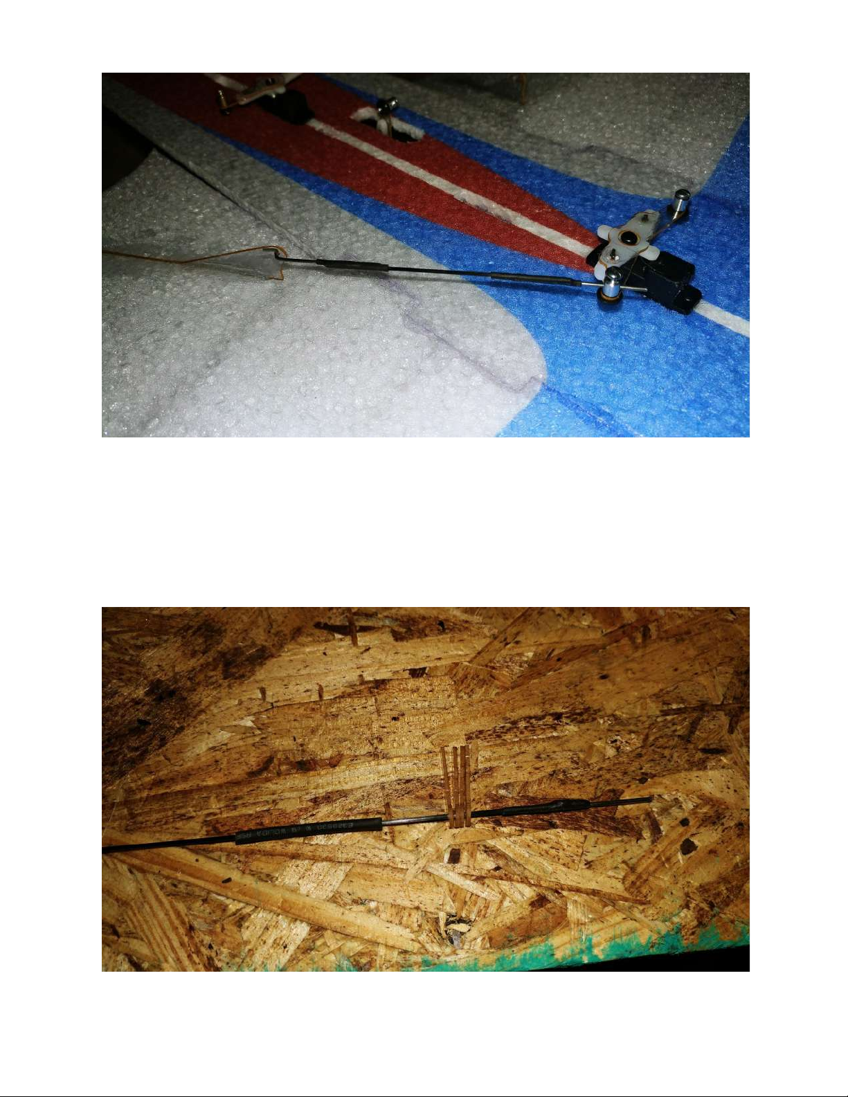
Shown above is the entire aileron linkage assembly for one aileron. Notice the
heat shrink over each glued end, as well as the straight end clamped into the
mini EZ connector on the servo arm.
Page 41
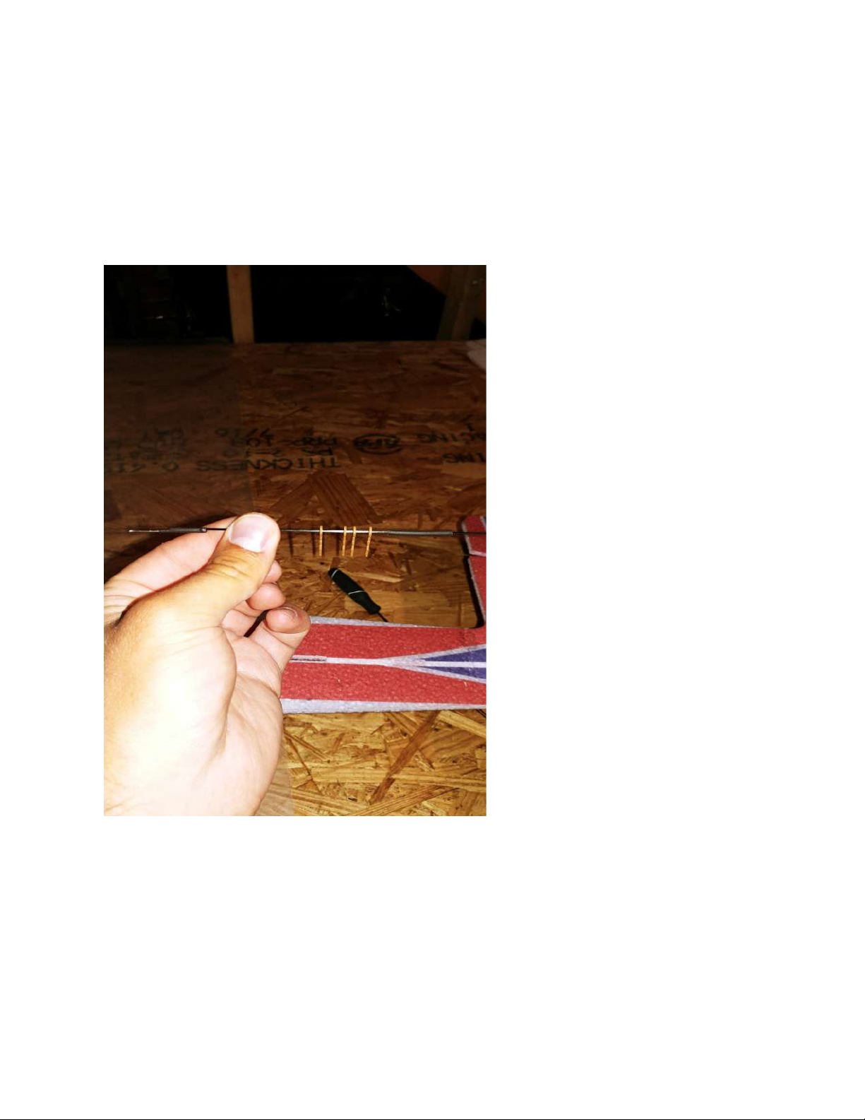
Shown above is the elevator linkage. Notice how the 4 guides are slid over the
linkage and the heatshrink is cut and slid on before the Z bend is glued. The
rudder linkage will be done the same way later on. You will be able to tell
where the guides will need to be glued in based on the slots in the fuselage.
Above is another view of the elevator linkage setup.
Page 42
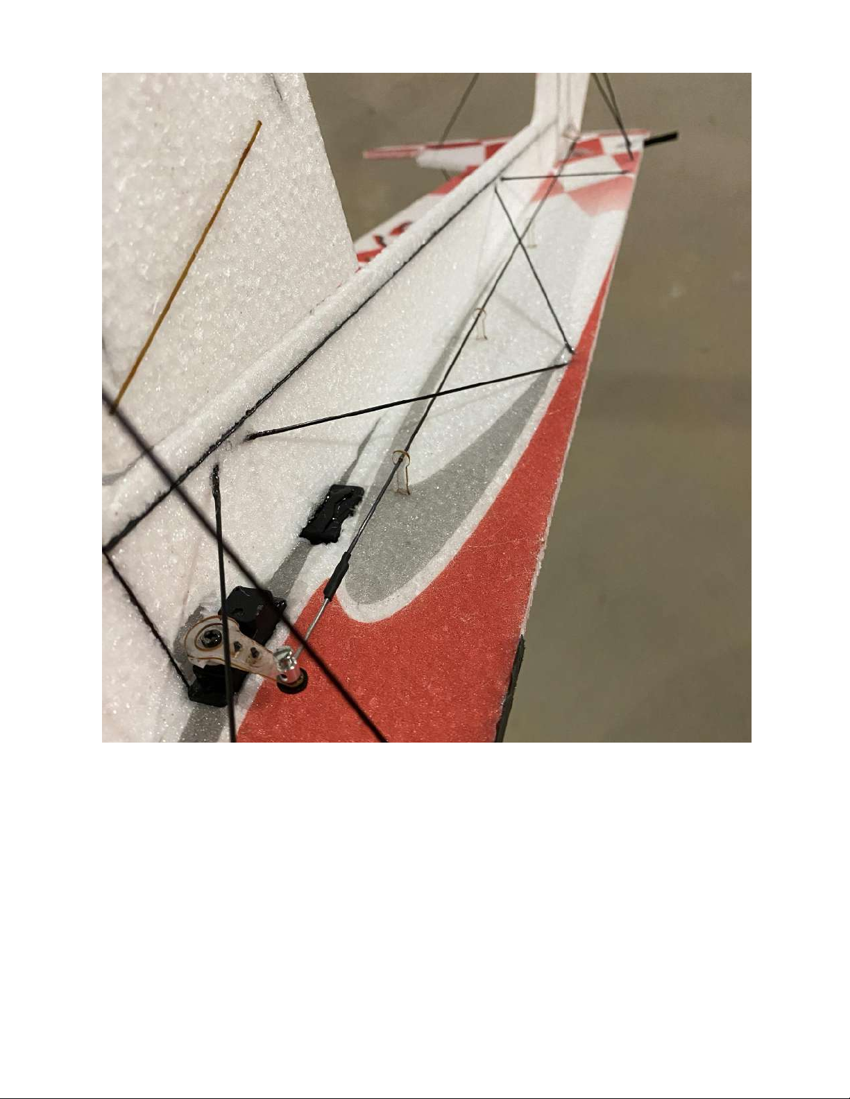
Above is the finished elevator linkage setup with the guides glued into the
fuselage and the elevator centered and clamped into the mini EZ connector.
Also shown is the elevator control horn. It may be easier to glue the horn in
after the linkage is assembled since the linkage is set up underneath the
fuselage.
Page 43
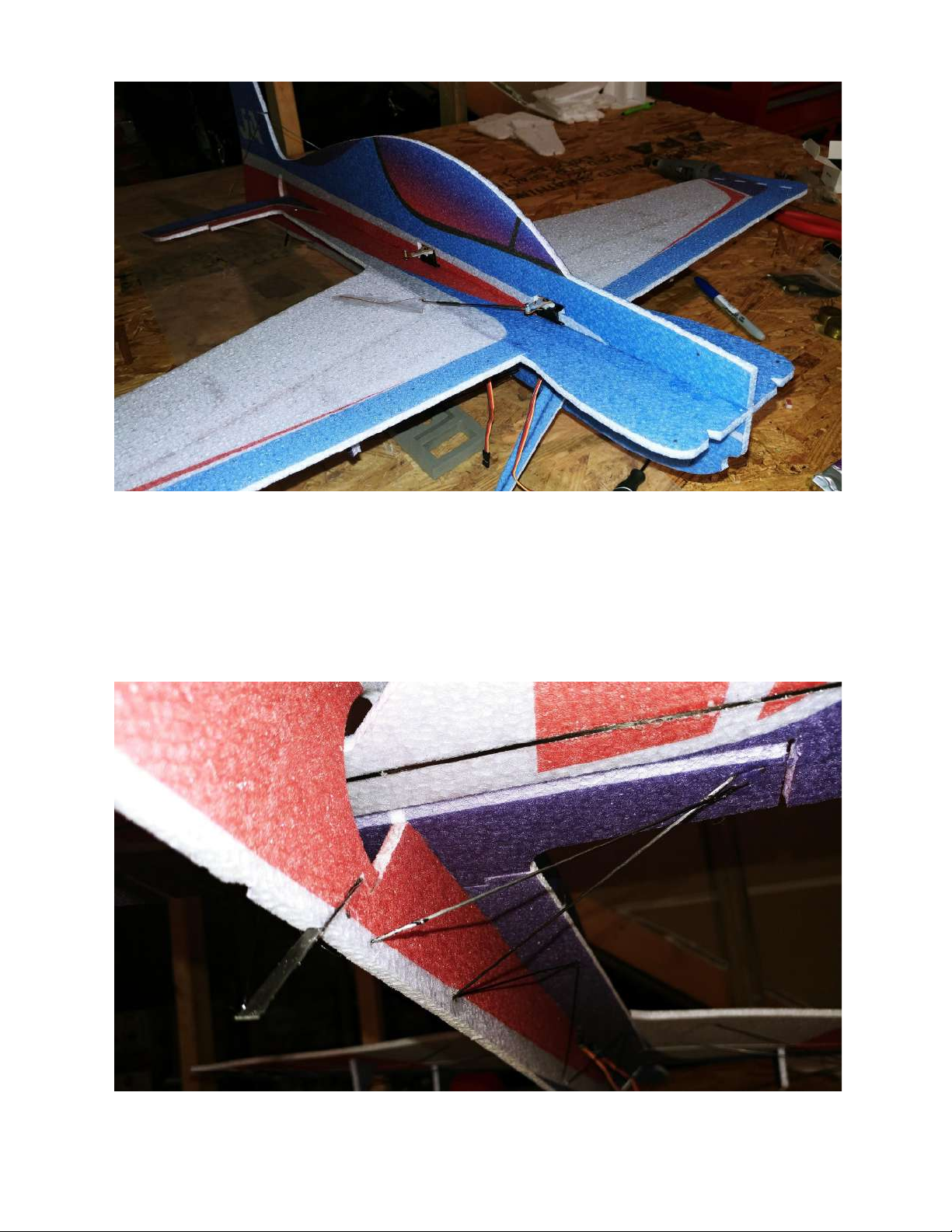
Once the aileron and elevator linkages are set up, use the same process as
glueing the bottom of the fuse to glue the top of the fuselage into place. Once
again, it is important to keep this as straight as possible.
Page 44
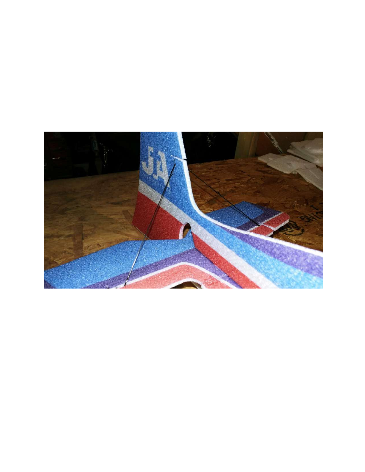
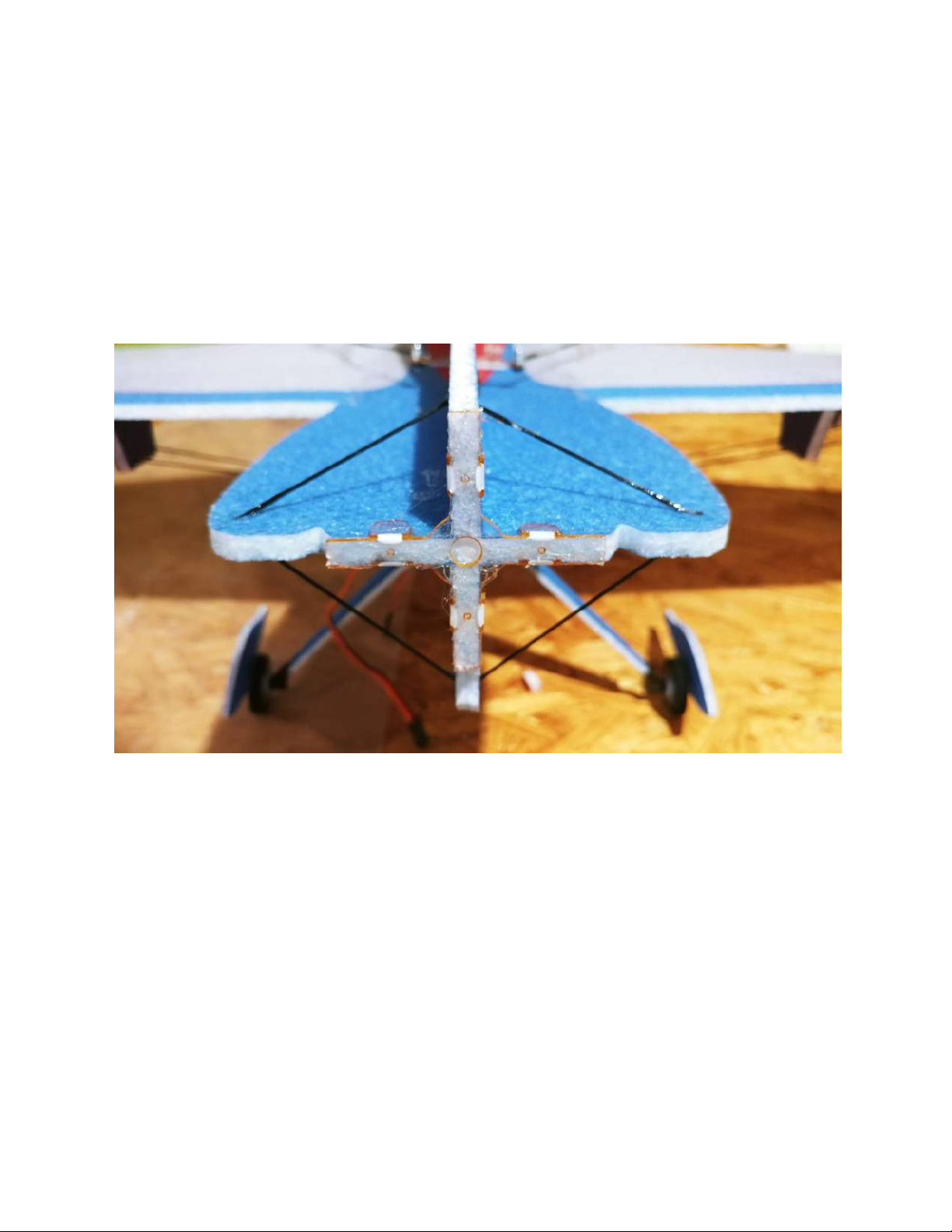
Now that the top of the fuselage is glued in, you can glue the other rear carbon
fiber rods to help strengthen the tail as shown above. They will be mounted
from the bottom of the horizontal tail to the rear of the bottom vertical
fuselage. Make sure they are glued in a location that allows for full down
elevator throw.
Shown above is the carbon rod that will go on each side of the fuselage. It will
be used to strengthen the horizontal stab and vertical stab.
Page 45
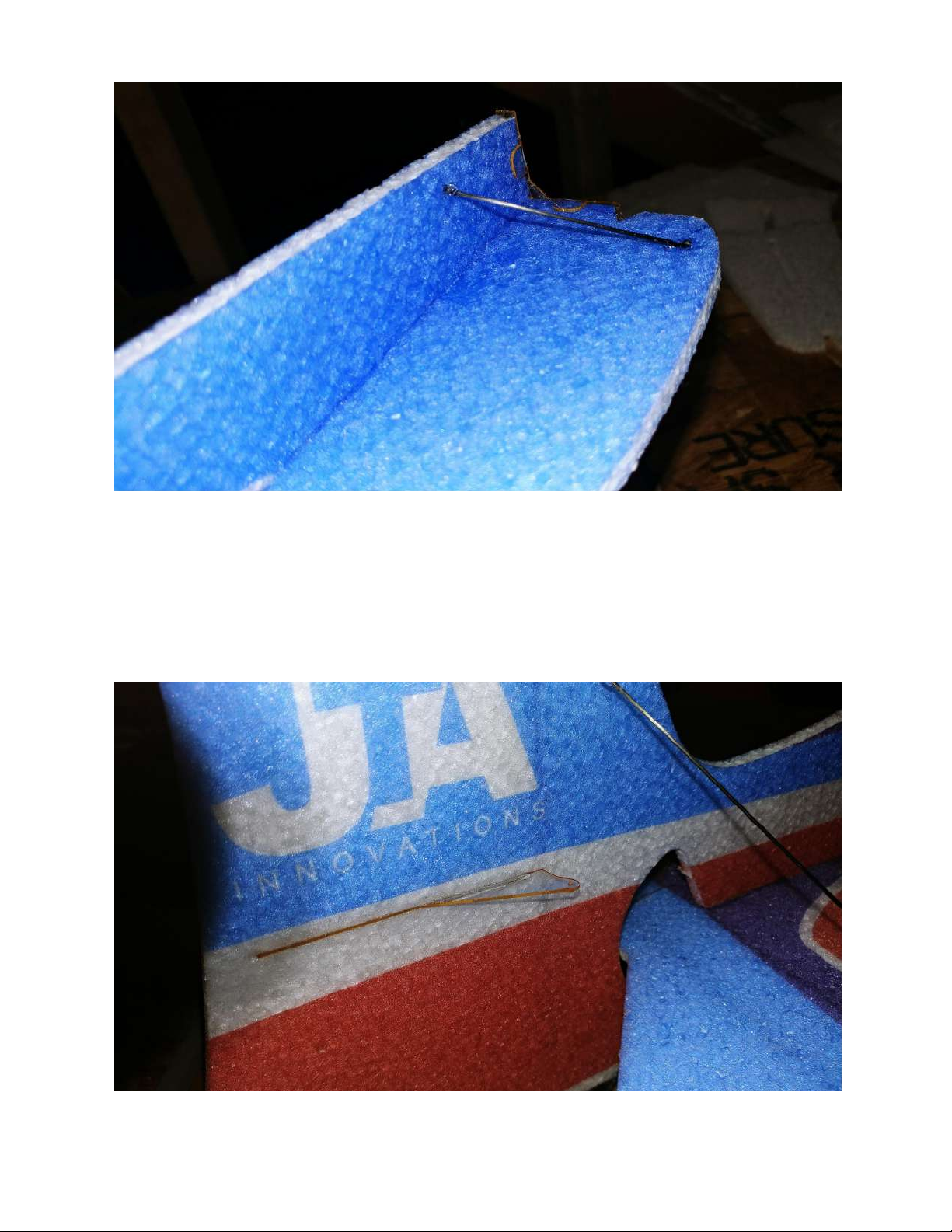
The final piece used for carbon fiber bracing will be the
rod used at the front of the airframe. Make sure that the fuselage is straight
while these pieces are setting.
Page 46
You can now locate the final long control horn and glue it into the slot on the
side of the rudder. This will be used for the rudder linkage that will be
constructed in the same way as the one used for the elevator. Once again, the
length for that linkage is 365mm. The guides for the rudder linkage will be
glued into the top of the vertical fuselage.
Locate the motor mount as shown above. Test fit the motor mount to the front
of the fuselage by bending the attached tabs 90 degrees and sliding it on
without glue. Once test fitted, place adhesive on the inside of the motor mount
covering every spot, then place again on the front of the fuselage making sure
everything is flush and lined up correctly.
Page 47
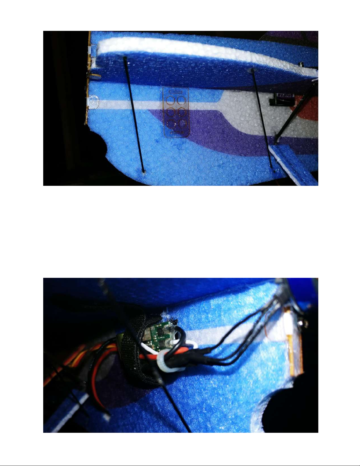
Notice above the plate glued onto the side of the fuselage. This can be used to
mount the electronic speed controller on the other side of the fuselage. The
two cutouts on the top and bottom of the plate is where the provided velcro
strap will slide through.
Page 48
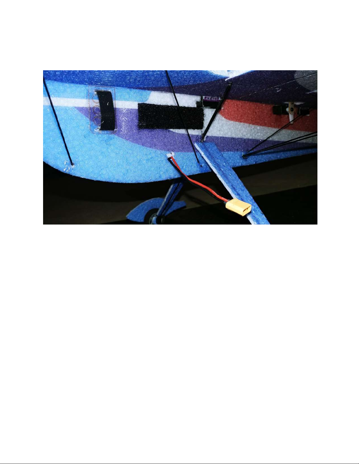
Shown above is the ESC mounted using the velcro strap and a supplied zip tie
is used to tie the ESC wires together.
The center of gravity and battery placement will depend on equipment used
and personal flying preferences. The long piece of velcro mounted above is the
location of the battery for this setup. To save space on the other side of the
fuselage, the battery connector is put through to the opposite side of the ESC
and receiver.
Page 49
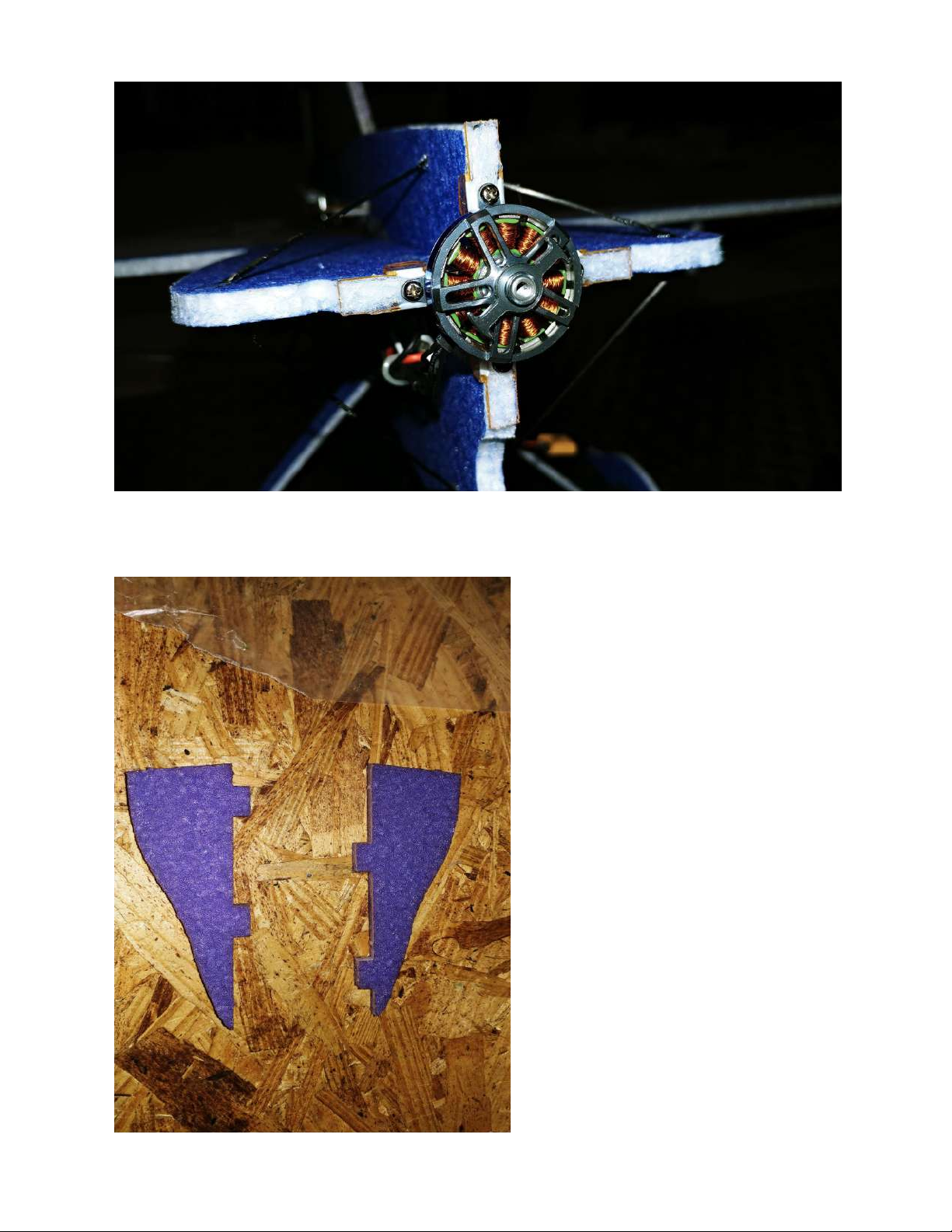
Shown above is the motor mounted to the provided motor mount.
Page 50
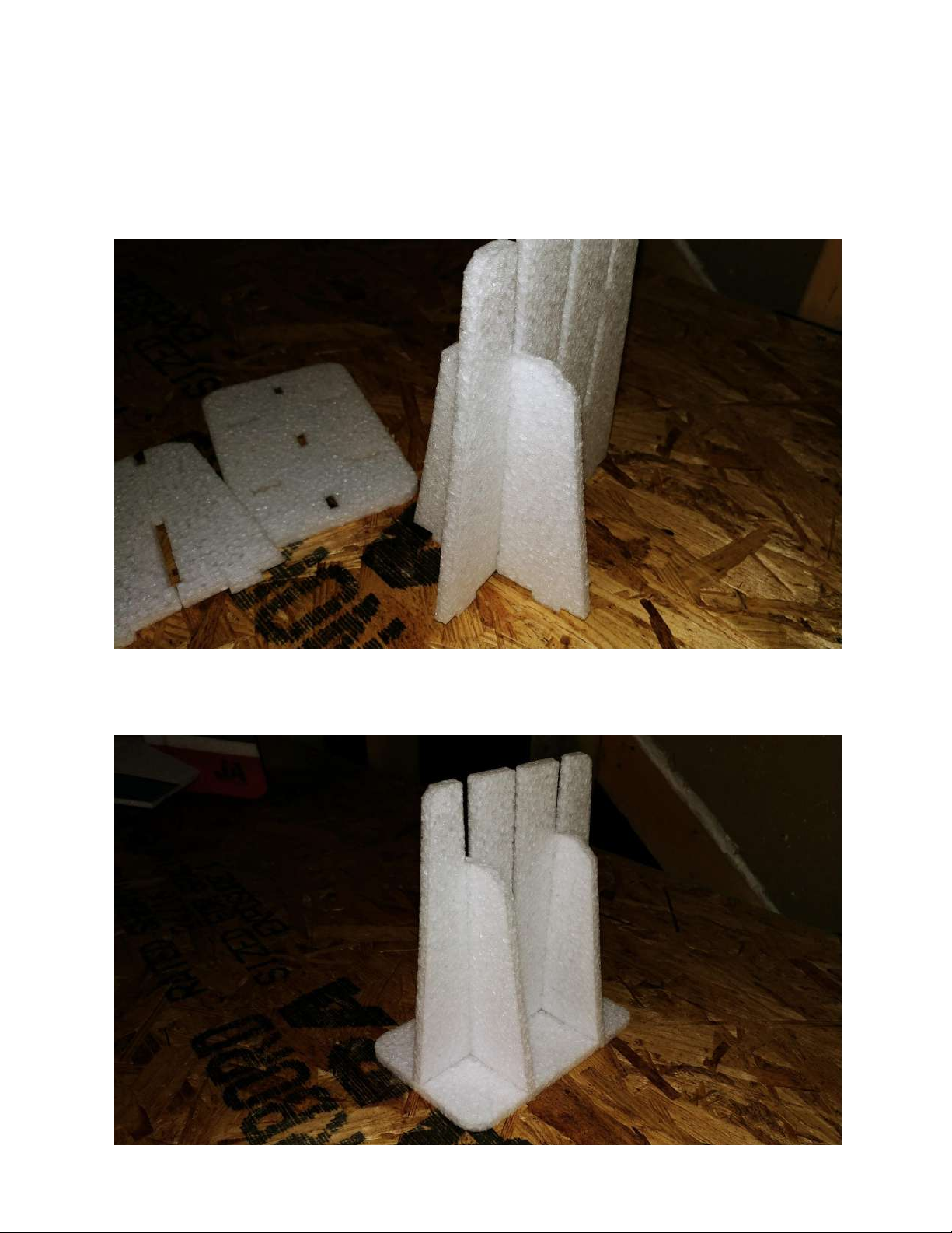
If desired, locate the side force generators that will be glued into the
counterbalances of the ailerons. *Some airframes may require the SFGs to be
glued into different locations along the wing.*
Shown above are the pieces included for the stand assembly.
Page 51

Message from Jase
Dear JTA Innovations customer,
The appreciation of you to express interest in our product is
highly valued. The foundation of this business was created on
passion for the hobby and is inspired by those who have helped
me experience it since I was a small child. I have been blessed
to meet several genuinely kind people in this hobby and I am
using this business to contribute my part to the cause of model
aviation. We hope that this purchase is a success for you and
that it brings the type of joy to you that only model aviation
provides. Please do not hesitate to contact us regarding any
type of question or concern. We are anxiously awaiting your
feedback on this product and I hope I will get the pleasure of
meeting you in person if I have not yet already. Once again,
thank you!
God bless,
Jase Dussia - Owner/Founder JTA Innovations, LLC
 Loading...