

Page 1
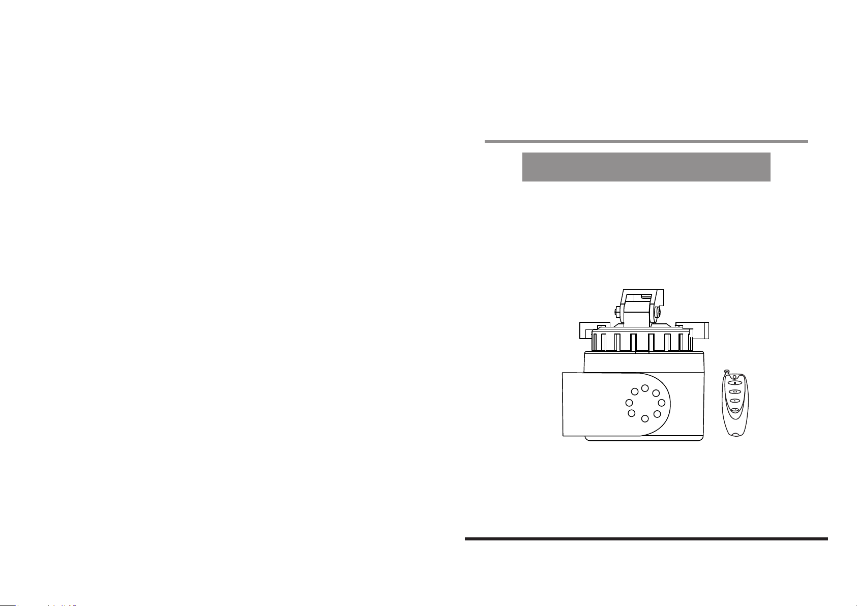
User Manual
Auto Pan Scan Platform
with Remote Control
Model No.: MP-7012
Includes:
- (1) Rotating Camera Platform
- (1) Remote Control
- (1) 9V AC/DC Adaptor
- (1) Platform mounting bracket and hardware
- (1) Extra Camera Mounting Plate
PLEASE READ CAREFULLY AND SAVE
This manual contains important information about this product's operation.
If you are installing this product for others, you must leave this manual -or a
copy- with the end user.
Page 2
No.: MP-7012
Contents
Safety and Hazard Notices
Major Operation Components
Installation
Camera Mounting
Wall Mounting
Cable Connection
Operating Procedures
Panning Range Adjustment
Technical Data
Trouble Shooting
Maintenance
Parts Included in This System
- (1) Rotating Camera Platform
- (1) Remote Control
- (1) 9V AC/DC Adaptor
- (1) Platform mounting bracket and hardware
- (1) Extra Camera Mounting Plate
3.
4.
4.
5.
5.
6.
6.
8.
9.
10.
10.
Page 3
Troubleshooting
Observe the safety notices under all circumstances!
Error Possible cause
Platform does not
rotate at all
Platform rotates, but
not smooth
• Check if power cable plug-in correctly
• Check if controller battery low. Change battery (screw open
the back cover then change a new 12V battery, Energizer
A27 or Duracell MN27 is recommended)
• The distance between platform and controller is too far.
Stand closer to control the platform.
• Weight overload. The platform is designed for smaller
camera under 7.0lb.
• Cable jammed. Stretch cable(s) attached to camera,
allowing platform to rotate.
• The distance between platform and controller is too far.
Stand closer to control the platform.
• Weight overload. The platform is designed for smaller
camera under 7.0lb.
• Cable jammed. Stretch cable(s) attached to camera,
allowing platform to rotate.
Other repairs as described above may only be performed by an
authorized technician.
Maintenance
The devices are maintenance-free. Only clean the outside of the devices
using a soft, dry cloth or a brush. Unplug prior to cleaning. Do not paint the
camera or the receiver. Do not disassemble. Disassembly voids the warranty.
Do not use any carboxylic cleaning agents or petrol, alcohol
or similar which will destroy the surfaces of the devices. Do
not use any sharp edged tools, screw drivers, metal brushes
or similar for cleaning.
Important!
Please read this Manual carefully
before installing or using these units.
WARNING- These units should ONLY be disassembled by an authorized
technician if service is required.
Safety Precautions
For correct and safe operation of this system, it is essential that installers,
end-users and service technicians should follow all safety procedures
outlined in this manual. Specific Warning and Caution statements (and/or
symbols) are marked on the units where needed.
Warning and Caution Statements
"WARNING" indicates a situation where failure to follow proper procedures
can cause personal injury.
"CAUTION" indicates a situation where failure to follow proper procedures
can cause damage to the equipment.
Important Safety Precautions
Please read before installing & using this product
Damages caused by non-compliance with this operating manual void the
warranty! We will not assume any liability for damages to items or persons caused
by improper handling or non-compliance with the safety notices! Any warranty
claim will be null and void in such cases.
- Make sure that all electric connections and connection cables between the devices of
the camera system as well as the devices to be connected meet the pertaining regulations and
are in conformity with the operating instructions.
- In schools, training facilities, hobby and self-help workshops, qualified personnel needs to
supervise the operation of electronic devices.
- Also observe the safety notices and operating instructions of the other appliances connected
to the system.
- Please contact an expert in case you have any doubts about the mode of operation, the safety
or connecting the appliances.
- Never plug-in or unplug the power supply with wet hands.
- Never tug on the power cords, use the plug to unplug it from the socket.
- Make sure that the power cables do not get crushed or damaged by sharp edges when
installing the devices.
- Never replace damaged power cables yourself! Take the device to a qualified repair
technician.
10. 3.
Page 4
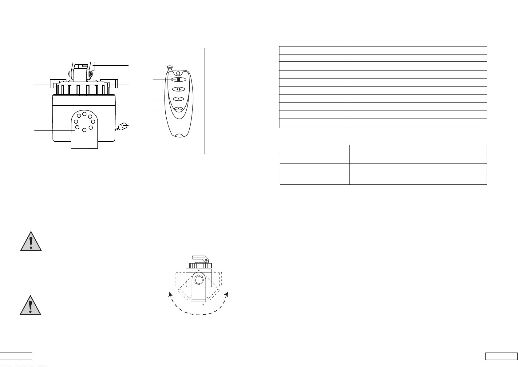
Major Operating Components
1
5
2
2
6
7
8
3
4
1. Camera Mounting plate
2. Pan Limit Stops
3. DC In for Platform Adaptor
4. Mounting Bracket
5. Stop Button
6. Auto Pan Button
7. Pan Left Button
8. Pan Right Button
Installation
Technical Data
Rotating Camera Platform
Operating voltage
Transmitting frequency
Modulation
Transmitting Range
Operating temperature
Maximum Load
Pan Angle
Pan Speed
Weight (w/o bracket)
Dimensions (w/o bracket)
Remote Control
Batt. Type 12V Alkaline Battery
Transmitting Frequency 315 MHz
Modulation
Transmitting Range
Note: You can buy replacement battery from following brands and battery codes:
CNB 27A, Duracell MN27, Energizer A27, Gold Peak GP27A, Golden Power A27,
Motorola SNN4176A, RadioShack ALK27A, Varta V27GA, Vinnic L828
9V/500mA
315MHz
FM / ASK
approx. 300ft at free visibility or 150ft indoor
14o F to 122o F
6.6lb
o
to Panorama View
0
o
per second
7
0.216lb
3.74 x 2.91 x 2.91 in
FM / ASK
approx. 300ft at free visibility or 150ft indoor
THIS UNIT IS DESIGNED FOR EITHER UPRIGHT OR HORIZONTAL
INSTALLATIONS.THE UNIT MUST BE INSTALLED IN A
WEATHERPROOFENCLOSURE OR A PROTECTED AREA.
Follow the instructions provided with mounting bracket.
Mount and mounting surface must be able to support the
weight of the pan/ tilt, camera and enclosure (if used). The
camera/ enclosure must be properly mounted and balanced
on the mounting bracket.
CAUTION!
STRONGLY NOT RECOMMEND TO MOUNT THE
PLATFORM INVERTED!!!
THE MAXIMUM LOAD FOR THE PLATFORM IS 6.6lb.
4. 9.
180
Page 5
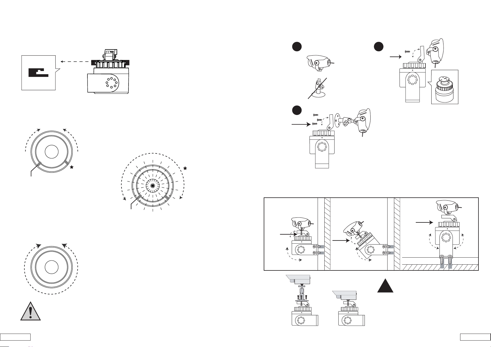
Panning Range Adjustment
1. Camera Mounting
Mount the camera/ enclosure to the platform bracket as follows:
Pan Limit Stops
Top
Bottom
Pan Stops
(Top View of the platform)
Front
The closer the stops,
Pan Stops
Rear
the wilder the angle.
Auto-Pan Operation
(Pan Stops Removed)
Front
Locate the 2 limit stops on the camera base.
The Pan stops are positioned on each side of pan switch
lever. The pan stops may be repositioned or removed
depending on the desired operation.
Front
Available rorating angle
Pan Stops
Rear
1
RECOMMENDED!
Loss camera bracket
OR
screw
2
screw
Top View
1. Wall Mounting
Balance the camera/ enclosure and adjust the unit to align with mounting holes. Fasten with the screws
screw
screw
screw
OR
The auto-pan function is controlled by the remote control
sensing changes in current flow through the pan motor.
When a pan stop is removed, the unit panned continuously
left or right for Panorama View.
!
Rear
CAUTION: THE PAN LIMIT STOPS SHOULD NOT BE
ADJUSTED WHILE UNIT IS OPERATING
8. 5.
X O
If you are using your own camera,
please loss camera stand then mount
camera only onto the platform
Page 6
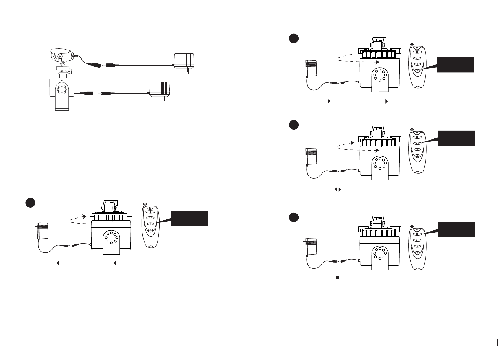
1. Cable Connection
Make all electrical connections. Leave sufficient loops of cable betweeen
camera/ enclosure and platform to allow for panning.
Operating Procedures
After the unit is installed and all wire connection are made. Operate the control unit to the desired
position by using the Remote Control.
1
2
Hold to pan,
Release to stop
2. Hold the button to pan right. Release button to stop.
3
Press to Auto
pan
3. By press the button to pan left and right automatically
Hold to pan,
Release to stop
1. Hold the button to pan left. Release button to stop.
4
Press to stop
Auto pan
4. By press the button to stop auto pan.
6. 7.
Page 7

Federal Communication Commission Interference Statement
This equipment has been tested and found to comply with the limits for a Class B digital device,
pursuant to Part 15 of the FCC Rules. These limits are designed to provide reasonable protection
against harmful interference in a residential installation.
This equipment generates, uses and can radiate radio frequency energy and, if not installed and used in
accordance with the instructions, may cause harmful interference to radio communications. Howe ve r,
there is no guarantee that interference will not occur in a particular installation. If this equipment does
cause harmful interference to radio or televi si on rece pt i on , whi ch can be determined by turning the
equipment off and on, the user is encouraged to try to correct the interference by one of the following
measures:
. Reorient or relocate the receiving antenna.
. Increase the separation between the equipment and receiver.
. Connect the equipment into an outlet on a circuit different from that to which the receiver is
connected.
. Consult the dealer or an experienced radio/TV technician for help.
FCC Caution :To assure continued compliance, any changes or modifications not expressly approved by the
party responsible for compliance could void the user's authority to operate this equipment. (Example - use only
shielded interface cables when connecting to computer or peripheral devices).
This device complies with Part 15 of the FCC Rules. Operation is subject to the following two
conditions:
(1) This device may not cause harmful interference, and (2) This device must accept any interference
received, including interference that may cause undesired operation.
 Loading...