

Page 1
Page 1/4
The Quality Connection
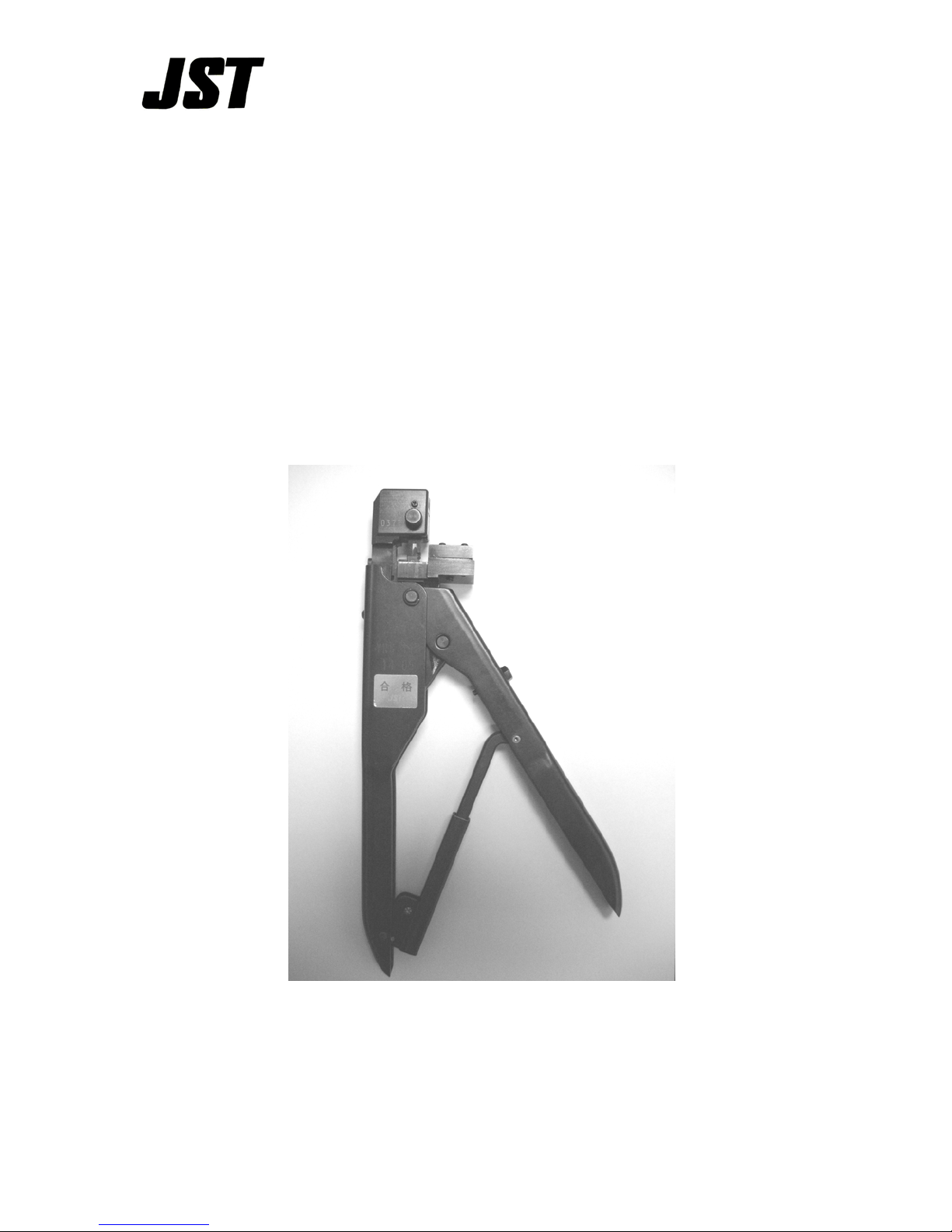
YRS SERIES
HAND CRIMP TOOL
Instruction Manual
.
Page 2

Page 2/4
The Quality Connection
Preface:
1) The YRS series hand tools are designed to crimp smaller sized open barrel
terminals that are side fed and attached to a carrier strip.
2) The tool was designed for small production lots, samples, and repairs.
3) Each tool includes a specification sheet which includes the tool part number,
the contact to be crimped, the specific wire to be used, the required tensile
strength, and the strip length for the wire .
4) The upper die has two crimp positions for different wire sizes. The die must be
set for the wire to be crimped.
5) The conductor and insulation barrel crimp heights are not adjustable.
Therefore, the wire noted on the tool specification must be used.
Precautions:
1) Make sure the correct combination of wire, terminal, and tool are used.
2) The tool does not hav e a release for the rat chet. Once a cycle is started it must
be completed. If the terminal is not positioned properly or there is a foreign
body stuck in the crimp do not force the handles closed. Doing so will likely
break parts on the tool. Instead remove the adjustment pin and the upper die.
After removing the die the process can be complete releasing the ratchet.
3) Check the following items prior to use:
a) Make sure the crimping dies are free from dama ge, rust, and debris.
b) Make sure the ratchet releases smoothly after the crimp is complete.
c) Visual inspection of crimped contact and tensi l e strength are good.
4) Do not use the tool for purposes other than crimpi ng.
5) Periodically add oil to the moving parts and pins on the tool. If the tool will not
be used for long period coat it in oil and store is a rust preventative bag.
6) Consult JST if the tool beaks or needs to be repai red.
Page 3

Page 3/4
The Quality Connection
Crimping Operation:
1) Squeeze the handles until the dies are completely
closed. The Ratchet will release allowing the
handles to open.
2) Remove the adjustment pin from the upper die and
then remove the upper die from the tool.
3) Select the side that matches the wire size that will be
used.
4) Refer to Fig. 2. Position the upper die and insert it
so the guide screw is inserted in the guide groove of
the upper die (on the insulation barrel side). The
guide screw prevents the die from being inserted the
wrong way. Do not remove the guide screw.
5) Insert the carrier strip of the terminals into the tool
between the terminal guide and the guide plate. The
insulation barrel of the terminal must be fed into the
groove on the guide plate as shown in Fig. 3. Feed
the terminals into the tool by hand until the first
terminal is in the crimping position over the anvils.
6) With the terminal in the crimping position lightly
squeeze the handles together until the upper
crimper touches the insulation barrel. Do not put
too much pressure on the terminal at this point.
Deforming the terminal will prevent the wire from
being inserted.
7) Insert a stripped wire into the upper die until the
insulation of the stripped wire lightly touches the
stripper as shown in Fig.4.
8) Holding the wire in the correct position squeeze
the handles until the ratchet releases.
9) Remove the terminal and make a visual inspection
of the completed crimped terminal.
Page 4

Page 4/4
The Quality Connection
Name of each part:
Caution:
1) Do not squeeze the handles with excessive force. The tools are factory
adjusted so that the ratchet will release with only about 20~30 kgf.
Excessive pressure may damage or break the di es.
2) Be sure the wire does not come off the stripper in the upper die when
crimping.
3) If it seems as if the cycle will not complete without excessive force stop and
remove the adjustment pin from the upper die. This will prevent the dies
from being damaged.
In line with a policy of continual product development, JST reserves the right to
change the specifications of the goods described in this manual at any time
without prior notice.
 Loading...