

Page 1
223
Features––––––––––––––––––––––––
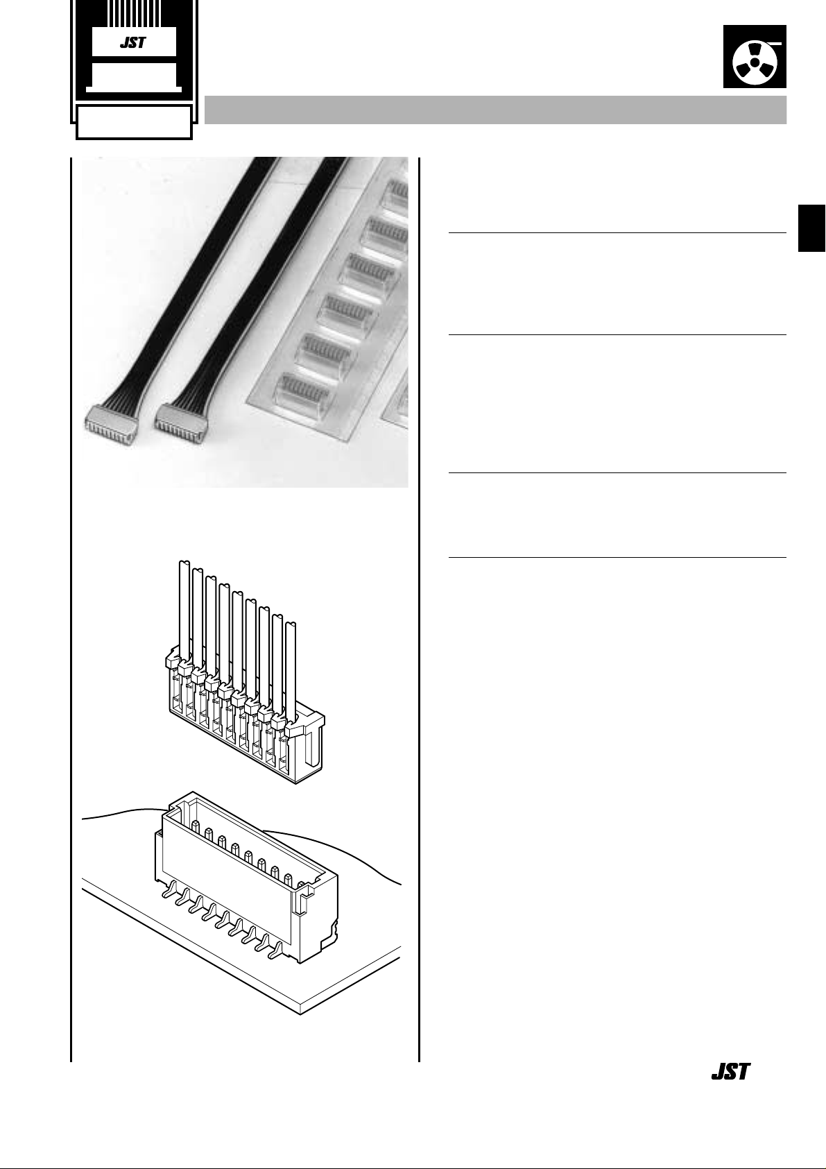
• Ultra-compact insulation displacement
connector
1.0mm (.039") pitch and only 3.0mm (.118") high (side entry
type). This connector is only about 61% as large as the
smallest conventional (JST) IDC designs.
• Header designed for vacuum pick and place
robotics
Although this shrouded header has locking features for its
mating receptacle, there are no holes in the header shroud
that would adversely effect vacuum grippig equipment. Since
there is enough flat surface for secure vacuum gripping, this
miniature surface mount connector is versatile for designers
and economic for manufacturing.
• Twin U-slot insulation displacement section
The insulation displacement section connected to each wire
consists of two tin-plated slots (twin U-slots), which ensures
reliable connection.
• 3-point grip construction
The 3-point insulation grip feature and the strain relief ensure a
firm grip on terminated wires and protection of the insulation
displacement connection from possible damage.
Specifications –––––––––––––––––––
• Current rating: 0.7A DC
• Voltage rating: 50V DC
• Temperature range: -25˚C to +85˚C(including temperature rise
in applying electrical current)
• Contact resistance: Initial value/20m Ω max.
After environmental testing/40m Ω max.
• Insulation resistance: 100M Ω min.
• Withstanding voltage: 500V AC/minute
• Applicable wire: AWG #30
Conductor/7 strands,
tin-coated annealed copper
Insulation O.D./0.56mm (.022")
* Contact JST for details.
Standards ––––––––––––––––––––––
0
Recognized E60389
1
Certified LR20812
SR CONNECTOR
Disconnectable Insulation displacement connectors
1.0mm
(.039") pitch
IDC
Emboss Tape
JST 9
Page 2
224
SR CONNECTOR
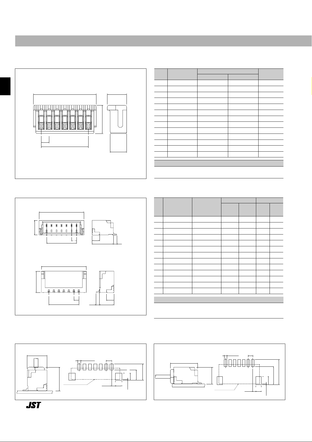
Receptacle–––––––––––––––––––––––––––––––––––––––––––––––––––––––––––––––
Cir-
Shrouded header –––––––––––––––––––––––––––––––––––––––––––––––––––––––––
2.9(.114)
B
4.25(.167)
1.5
(.059)
0.7(.028)
A
1.0
(.039)
A
4.25(.167)
0.7(.028) 2.9(.114)
1.5
(.059)
B
1.0
(.039)
Material and Finish
Cir-
cuits
Top entry
type
Dimensions mm(in.)Q'
ty / reel
Top
entry
type
Side
entry
type
B
2
3
4
5
6
7
8
9
10
11
12
13
14
BM02B-SRSS-TB
BM03B-SRSS-TB
BM04B-SRSS-TB
BM05B-SRSS-TB
BM06B-SRSS-TB
BM07B-SRSS-TB
BM08B-SRSS-TB
BM09B-SRSS-TB
BM10B-SRSS-TB
BM11B-SRSS-TB
BM12B-SRSS-TB
BM13B-SRSS-TB
BM14B-SRSS-TB
1.0(.039)
2.0(.079)
3.0(.118)
4.0(.157)
5.0(.197)
6.0(.236)
7.0(.276)
8.0(.315)
9.0(.354)
10.0(.394)
11.0(.433)
12.0(.472)
13.0(.512)
4.0(.157)
5.0(.197)
6.0(.236)
7.0(.276)
8.0(.315)
9.0(.354)
10.0(.394)
11.0(.433)
12.0(.472)
13.0(.512)
14.0(.551)
15.0(.591)
16.0(.630)
3,000
3,000
3,000
3,000
3,000
3,000
3,000
3,000
3,000
3,000
3,000
3,000
3,000
1,500
1,500
1,500
1,500
1,500
1,500
1,500
1,500
1,500
1,500
1,500
1,500
1,500
Contact: Copper alloy, copper-undercoated, tin/lead plated
Wafer: Polyamide, UL94V-0, natural (ivory)
Solder tab: Brass, copper-undercoated, tin/lead plated
A
Side entry
type
SM02B-SRSS-TB
SM03B-SRSS-TB
SM04B-SRSS-TB
SM05B-SRSS-TB
SM06B-SRSS-TB
SM07B-S RSS-TB
SM08B-SRSS-TB
SM09B-SRSS-TB
SM10B-SRSS-TB
SM11B-SRSS-TB
SM12B-SRSS-TB
SM13B-SRSS-TB
SM14B-SRSS-TB
Side entry type
Note: 1. The products listed above are supplied on embossed-tape.
2. Contact JST for the top entry type headers with suction cap.
PC board layout (viewed from component side) and Assembly layout––––––––––––––––––
2.95(.116)
4.85(.191)
Shrouded header
0.6 ± 0.05
(.024 ± .002)
0.7 ± 0.1
(.028 ± .004)
4.0 ± 0.1
(.157 ± .004)
0.2 ± 0.1
(.008 ± .004)
5.55 ± 0.1
(.219 ± .004)
1.0 ± 0.05
(.039 ± .002)
1.8 ± 0.1
(.071 ± .004)
1.2 ± 0.1
(.047 ± .004)
Note:
1. Tolerances are non-cumulative: ±0.05mm(±.002" ) for all centers.
2. Dimensions above should serve as a guideline. Contact JST for details.
Side entry type
4.9(.193)
2.9(.114)
Shrouded header
0.6 ± 0.05
(.024 ± .002)
0.7 ± 0.1
(.028 ± .004)
2.65 ± 0.1
(.104 ± .004)
0.2 ± 0.1
(.008 ± .004)
4.2 ± 0.1
(.165 ± .004)
1.0 ± 0.05
(.039 ± .002)
1.8 ± 0.1
(.071 ± .004)
1.2 ± 0.1
(.047 ± .004)
Top entry type
Top entry type
cuits
3.6(.142)
2.45(.097)
2.1(.083)
10
11
12
13
14
1.0
(.039)
B
A
Model No.
2
02SR-3S
3
03SR-3S
4
04SR-3S
5
05SR-3S
6
06SR-3S
7
07SR-3S
8
08SR-3S
9
09SR-3S
10SR-3S
11SR-3S
12SR-3S
13SR-3S
14SR-3S
Dimensions mm(in.)
A
1.0(.039)
2.0(.079)
3.0(.118)
4.0(.157)
5.0(.197)
6.0(.236)
7.0(.276)
8.0(.315)
9.0(.354)
10.0(.394)
11.0(.433)
12.0(.472)
13.0(.512)
B
3.0(.118)
4.0(.157)
5.0(.197)
6.0(.236)
7.0(.276)
8.0(.315)
9.0(.354)
10.0(.394)
11.0(.433)
12.0(.472)
13.0(.512)
14.0(.551)
15.0(.591)
Q
’
ty / box
3,000
3,000
3,000
2,000
2,000
2,000
2,000
2,000
2,000
2,000
2,000
2,000
2,000
Material and Finish
Contact: Phosphor bronze, tin-plated
Housing: Polyamide 66, UL94V-0, natural (ivory)
Page 3

225
Taping specifications ––––––––––––––––––––––––––––––––––––––––––––––––––––––
Side entry type
Cir-
cuits
Top
entry
type
Side
entry
type
2 to 3
4
5 to 7
8
9 to 14
Q'ty / reel
Top
entry
type
Side
entry
type
Top
entry
type
Side
entry
type
Top
entry
type
Side
entry
type
Top
entry
type
Side
entry
type
Taping dimensions mm(in.)
FSWW1
Reel dimensions mm(in.)
5.5(.217)
7.5(.295)
7.5(.295)
11.5(.453)
11.5(.453)
5.5(.217)
5.5(.217)
7.5(.295)
7.5(.295)
11.5(.453)
4.75(.187)
6.75(.266)
6.75(.266)
10.75(.423)
10.75(.423)
4.75(.187)
4.75(.187)
6.75(.266)
6.75(.266)
10.75(.423)
12(.472)
16(.630)
16(.630)
24(.945)
24(.945)
12(.472)
12(.472)
16(.630)
16(.630)
24(.945)
13.5(.531)
17.5(.689)
17.5(.689)
25.5(1.004)
25.5(1.004)
13.5(.531)
13.5(.531)
17.5(.689)
17.5(.689)
25.5(1.004)
1,500
1,500
1,500
1,500
1,500
3,000
3,000
3,000
3,000
3,000
Top entry type
SR CONNECTOR
Note:
1. Specifications conform to JIS C 0806. The tape width, connector recess hole dimensions, etc. are determined by the number of circuits and external shape of
the connector to be loaded.
2. Specifications are subject to change without prior notice.
Feeding direction
Feeding direction
Feeding direction
1.55±0.05
(.061±.002)dia.
4.0±0.1
(.157±.004)
13.0(.512)dia.
2.0±0.1
(.079±.004)
F±0.1
(W1
1.75±0.1
W1
(.069±.004)
(.004)
(S)
+2.5
-
1.0
+.098
-
.039
)
W±0.3(.012)
2.0 ± 0.5
(.079 ± .002)
Cover tape
± 2.0
380
[100(3.937)dia.]
(14.961 ± .079)dia
Carrier tape
Carrier tape
Tail tape
(Unloaded area)
40(1.575)
min.
Feeding direction
4.0 ± 0.1
1.55 ± 0.05
(.061 ± .002)dia.
(.157 ± .004)
Connector
loaded area
(.079 ± .004)
2.0 ± 0.1
1.75 ± 0.1
F ± 0.1
Cover tape leader area
Lead tape
(Unloaded area)
20 vacancies min.
400(15.748) min.
Cover tape
(.069 ± .004)
(.004)
W ± 0.3(.012)
(S)
Carrier tape
12±0.1
(.315±.004)
0.38±0.05
(.015±.002)
4.55
(.179)
8.0 ± 0.1
(.315 ± .004)
0.38 ± 0.05
(.015 ± .002)
3.25
(.128)
Page 4

WWW.ALLDATASHEET.COM
Copyright © Each Manufacturing Company.
All Datasheets cannot be modified without permission.
This datasheet has been download from :
www.AllDataSheet.com
100% Free DataSheet Search Site.
Free Download.
No Register.
Fast Search System.
www.AllDataSheet.com
 Loading...