


Accessories - ND0402EN - 2018/10
MANUAL
VS 100, VS 110, VS 120, VS 200
Isolating Vent Valve
Isolating Valve
Testing Vent Valve
Two Valve Manifolds
Operating pressure up to 42 MPa.
•
Operating temperature up to 500 °C.
•
Material stainless steel 1.4541.
•
Sealing component selection from different
•
material: Graphite, PTFE, PEEK, Viton, EPDM.
JSP, s. r. o.
Industrial Controls
CZ Raisova 547, 506 01 Jičín
+420 493 760 811 • jsp@jsp.cz
Gland packing adjuster.
•
Seat diameter 4 mm.
•
EU Type Examination Certificate
•
according to Directive PED 2014/68/EU.
SK Karloveská 63, 841 04 Braslava
+421 2 6030 1080 • predaj@jsp.sk
www.jsp.cz

Valves VS 100, VS 110, VS 120 and Two Valve Manifolds VS 200
Contents
1. General instructions and information ..........................................................................................................3
1.1 Symbols used ..............................................................................................................................................3
1.2 Scope of delivery .........................................................................................................................................3
1.3 Description of the delivery and packing .......................................................................................................3
1.4 Storage ........................................................................................................................................................3
1.5 Installation and commissioning ....................................................................................................................3
1.6 Spare parts ..................................................................................................................................................3
1.7 Repairs ........................................................................................................................................................3
1.8 Warranty ......................................................................................................................................................3
2. End of service and disposal .........................................................................................................................3
2.1 End of service ..............................................................................................................................................3
2.2 Disposal .......................................................................................................................................................3
3. Product description ....................................................................................................................................... 4
3.1 Application ...................................................................................................................................................4
3.2 Description ...................................................................................................................................................4
3.3 Dimensional drawings..................................................................................................................................4
4. Installation, operation and maintenanceu ...................................................................................................5
4.1 Installation and commissioning ....................................................................................................................5
4.2 Interconnection diagram ..............................................................................................................................5
4.3 Examples of mounting of the manifolds in operation ...................................................................................5
4.4 Examples of mounting with brackets ...........................................................................................................6
4.5 Connection of impulse piping by means of cutting rings .............................................................................6
4.6 Operation and maintenance ........................................................................................................................7
5. Product specifications...................................................................................................................................7
5.1 Technical specifications ...............................................................................................................................7
5.2 Supplementary parameters .........................................................................................................................7
5.3 Operation conditions ....................................................................................................................................9
6. Tests, certificates and standards ................................................................................................................10
6.1 Tests and certificates .................................................................................................................................10
6.2 Marking and type tag information ..............................................................................................................10
7. Optional accessories ...................................................................................................................................10
7.1 Optional accessories to connection of impulse piping ...............................................................................10
8. Ordering information ...................................................................................................................................11
8.1 Ordering table ............................................................................................................................................11
Contacts ...........................................................................................................................................................15
- 2 -

Valves VS 100, VS 110, VS 120 and Two Valve Manifolds VS 200
1. General instructions and information
1.1 Symbols used
Symbol of warning; for safe use it is necessary to
proceed according to the instructions
Symbol CE certifies compliance of the product with
EU directives and the respective government
directives
The product does not belong to public waste and it is
subjected to separate collection
1.2 Scope of delivery
With the product is delivered:
- manual for installation, operation and maintenance
Upon request can be provided:
- protocol on executed tests
- copy of the Inspection certificate 3.1 acc. to EN 10204 for
material of the main body
- copy of the EU Type Examination Certificate acc. to Directive
PED 2014/68/EU
1.3 Description of the delivery and packing
The product is packaged in a protective cover and provided
with an identification label with a mark of the output control.
The product must not be exposed to direct rain, vibrations and
shocks during transport.
presented. The claiming party shall give identification of the
product, number of the delivery note and description of the
fault or defect.
The manufacturer is not responsible for any defects caused
by improper storage, incorrect connection, damages caused
by external effects, in particular by effects of factors with
excessive values, unqualified installation, improper operation
or common wearing.
2. End of service and disposal
2.1 End of service
In case that the manifold with a pressure or pressure
difference sensor is under pressure, the sensor and
manifold shall not be dismounted. During the end
of operation or manifold replacement, before manifolds
dismounting is necessary to switch over the possible regulation
loop to manual operation or accept another suitable measure to
prevent any possible damages connected with end of service
of the pressure sensor. Then the supply of pressure medium
is closed, pressure medium from the sensor and manifold is
discharged and the manifold is dismounted.
2.2 Disposal
The products do not contain any environmentally
hazardous parts. When disposing packages, destroyed
or irreparably damaged products, proceed according to
local regulations.
1.4 Storage
The products shall be stored at temperatures from -20 to +50
°C and maximum relative humidity 80 % in the rooms with
elimination of condensation of water vapours on the products.
The stored products shall not be exposed to any shocks,
vibrations and effects of harmful vapours and gases.
1.5 Installation and commissioning
During installation, commissioning, operation and maintenance
follow the instructions in chapter 4.
1.6 Spare parts
Any of the compact parts of the product can be also ordered
as a spare part if there is not required special procedures
or technological operations for the exchange.
1.7 Repairs
Products are repaired by the manufacturer. The products for
repair should be sent in a packing that guarantees damping
of shocks and vibrations and protects against damage during
transport.
1.8 Warranty
Products are covered by a warranty for a period of 24 months
from the delivery date on the delivery note. The manufacturer
guarantees technical and operational parameters of the
products within scope of the applicable documentation.
Warranty period is specified with individual items and begins
from the day of takeover of the goods by the purchaser or
delivery to the carrier. Any claims concerning to defects of the
goods together can be filed in writing with the manufacturer
within the warranty period and the claimed product shall be
- 3 -
Valves VS 100, VS 110, VS 120 and Two Valve Manifolds VS 200
3. Product description
VS 100, VS 110, VS 120, VS 200
Isolating Vent Valve
Isolating Valve
Testing Vent Valve
Two Valve Manifold
Operating pressure up to 42 MPa.
•
Operating temperature up to 500 °C.
•
Material stainless steel 1.4541.
•
Sealing component selection from different
•
material: Graphite, PTFE, PEEK, Viton, EPDM.
Gland packing adjuster.
•
Seat diameter 4 mm.
•
EU Type Examination Certificate
•
according to Directive PED 2014/68/EU.
3.1 Application
Isolating valves are used to shut off the supply of pressured
medium to the pressure sensor. In addition, the valve type with
a small deaeration valve (VS 100, VS 120) allows discharge of
mud or deaeration of the impulse piping. VS 120 valve, thanks
to the side screwing, allows connection of other equipment to
pressure medium. Individual types of the valves are designed
for direct installation on a pressure sensor or for installation
between the impulse piping.
The two valve manifold VS 200 is used to shut off the supply
of pressured medium to the pressure sensor, allows discharge
of mud or deaeration of the impulse piping and possibly serves
to connect other equipment to pressure medium. The manifold
is designed for direct installation on a pressure sensor or for
installation between the impulse piping.
3.2 Description
All parts of the valve is made of stainless steel 1.4541 except
the sealing ball and spindle gland. As a sealing element of the
valve is used a ball, embedded into the valve spindle face and
closing the through seat with diameter 4 mm. Material of the
sealing ball is optional; it could be made of quenched stainless
steel 1.4125, ceramics Si3N4 or plastic PTFE 325. The valve
spindle of the standard version is sealed using a FPM (Viton)
or EPDM O-ring; in both cases with two Teflon supporting rings.
In case of valves with gland packing adjuster it is possible to
choose the sealing material PTFE, Graphite or PEEK. The
wide range of dimensions of the input and output screwing
allows installation of the valve into a welded on piece, on a
sleeve with a transition connection, into a sensor screwing or
connection of the impulse piping using a welding on nipple,
welding on plow or single cutting ring for piping diameters 8, 10
mm, or double cutting ring for piping diameters 12 or 14 mm.
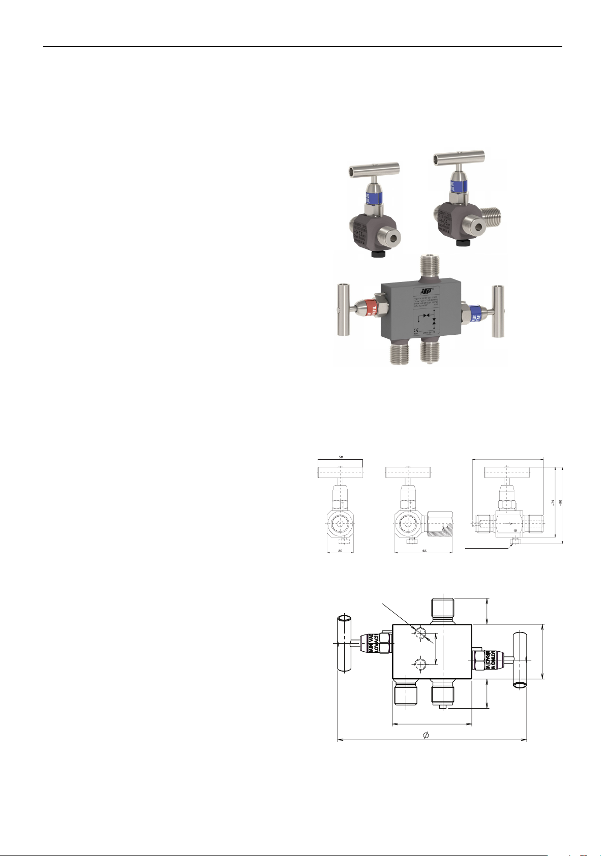
3.3 Dimensional drawings
VS 100, VS 110
VS 200
2x M10
28
71
169
VS 100, VS 110, VS 120 VS 120
66 ÷ 82 (acc. to connection threads)
Vent screw
only for VS 100, VS 120
26 23
49
- 4 -

Valves VS 100, VS 110, VS 120 and Two Valve Manifolds VS 200
4. Installation, operation and maintenanceu
4.1 Installation and commissioning
4.1.1 General
The shut off valve is fixed using a connecting screwing,
between the impulse piping or directly on the pressure
sensor. The impulse piping with diameter 12 or 14 mm
is connected by welding to the plow or nipple, see Fig. 2. To
ensure correct position of the nipple or plow, after installation it
shall be welded together with the shut off valve.
Before installation, the impulse piping shall be cleaned from all
dirt. After welding it shall be disconnected from the manifold
and purged to remove any possible dirt from welding.
Piping with outer diameter 8, 10, 12 or 14 mm can be also
connected by using a cutting ring. The minimum length of the
impulse piping to the first bend shall be 33 mm from the pipe
face. The pipe face shall be cut off perpendicularly and the inner
and outer edges shall be deburred. To prevent penetration of
any possible dirt between the contact surfaces, all part shall be
properly cleaned before installation.
Before connection of the sensor it is recommended to test correctness of connection (welding) of the shut off valve by pressurization of the impulse piping.
When both connections of threaded parts are made of
stainless steel, there is danger of galling (formation of
cold weld). This can also occur during ordinary screwing by hand without using tightening key. If the cold weld is
made, the thread is then damaged and parts are unusable. Before first screwing, it is therefore necessary to check whether
threads are free of impurities (and clean if needed) and then
treat the threads against galling (formation of cold weld) by
appropriate lubricant. For example use paste G-Rapid plus or
Lukosan M11 (in case of connection for oxygen). For tapered
threads is usually used Teflon tape. Threads with silver covered
surface do not have to be lubricated against galling.
4.1.2 Commissioning
After connection or welding of the impulse piping the shut
offvalve is ready for operation.
After installation of a shut off valve into piping it is necessary to
carry out deaeration of the piping. Deaeration for shut off valve
VS 100 and VS 120 can be done by deaeration screw M6. In
another case the deaeration is done by releasing of air bubbles
by knocking on the piping. The whole system can be flooded
by condensate when the thermal circuit is shut down and the
valve is closed.
In case of a leakage of the spindle gland with valve having
gland packing adjuster, the leakage can be eliminated by
tightening the adjuster screw and the lock nut.
4.1.3 Cleaning the manifold
Clogged manifold may be cleaned only if pressure
medium in the impulse piping is completely disconnected.
Before cleaning of a clogged fitting, screw out the small
valve(s) from the basic body. First remove the valve lock
pin, then screw out the valve and clean the interconnection
channels eventually the valve seat. When cleaning the fitting,
pay attention to the seating (sealing) edge of the valve to
prevent its damage.
Before installation of the valve into the fitting body it is
necessary to screw in the valve spindle up to the stop into the
valve body. To improve tightening and sealing of the valve in the
fitting it is recommended to apply a Teflon tape or a liquid Teflon
compound on the seating surface behind the valve threads.
Tighten the valve to 55 Nm and then press in the locking pin.
In case of cleaning of a manifold designed for use with
oxygen, avoid staining of individual parts of the manifold
with grease. The threads and sealing joints may be
lubricated only by a paste approved for use with oxygen.
4.2 Interconnection diagram
VS 100 VS 110 VS 120 VS 200
4.3 Examples of mounting of the manifolds in operation
Bracket for wall mounting Bracket for pipe mounting Shim for mounting of VS 200
- 5 -

Valves VS 100, VS 110, VS 120 and Two Valve Manifolds VS 200
4.4 Examples of mounting with brackets
4.5 Connection of impulse piping by means of cutting rings
21 4
3
Max. deviation 0.5°
Max. odchylka 0,5°. Odhrotovat hrany trubky.
Deburr edges of the pipe.
5 6
Clean threads and contact surfaces.
Očistit závity a styčné plochy.
87 109
Nasadit matici a kroužek
Install a nut and ring on the pipe.
na trubku.
Correct
správně
Slide in the pipe down to
Trubku zasunout na dno
Wrong
špatně
* Tighten by 1 1/2 turn for single cutting ring (codes 04, 13) and by 1 1/4 turn for double cutting ring (codes 22, 24).
* O 1 1/2 otáčky pro jednoduchý zářezný kroužek (kódy 04, 13) a o 1 1/4 otáčky pro dvojitý zářezný kroužek (kódy 22, 24)
the bottom and tighten it
a matici dotáhnout rukou. Označit polohu matice.
by hand.
Mark position of the nut.
Tighten the nut using a wrench*
Dotáhnout matici
klíčem
- 6 -
.*

Valves VS 100, VS 110, VS 120 and Two Valve Manifolds VS 200
4.6 Operation and maintenance
The device is attendance- and maintenance-free.
Only in case of a leakage of the spindle gland (version with
gland packing adjuster), the leakage can be eliminated by
tightening the adjuster screw (position 4). Before tightening
the screw loosen the lock nut (position 5). Tightening torque of
gland packing adjuster is 15 Nm. After tightening the adjuster
retighten the lock nut.
2
4
9
5
1
6
8
7
8
3
1 - Valve body
2 - Spindle
3 - Seat packing
4 - Vent screw
5 - Nut
6 - Pressure ring
7 - Carrier ring
8 - Gland packing
9 - Tag
5. Product specifications
5.1 Technical specifications
Operation pressure:
up to 42 MPa
Operation temperature:
up to 500 °C
5.2 Supplementary parameters
Materials:
manifold body stainless steel 1.4541
sealing ball of valve stainless steel 1.4125
(X105CrMo17)
ceramics Si3N4,
plastic PTFE 325
vent screw stainless steel 1.4034
O-ring EPDM, Viton
carrier rings teflon
dust cap silicone rubber
gland packing adjuster PTFE, Graphite, PEEK
welding nipple carbon steel 1.0570
steel 1.7715
stainless steel 1.4541
welding cone carbon steel 1.0570
steel 1.7715
stainless steel 1.4541
cutting ring stainless steel 1.4571
Weight without accessories:
VS 100 0.35 kg
VS 110 0.32 kg
VS 120 0.45 kg
VS 200 1.1 kg
- 7 -

Valves VS 100, VS 110, VS 120 and Two Valve Manifolds VS 200
Table 1.
Chemical resistance of sealing materials
Medium Viton EPDM PTFE Grafit PEEK
Acetone - - + + +
Acetylene + + + + +
Gas + - + + +
Water solution - + + + +
Ammoniac
Ethylene + + + +
Hydraulic liquids Fireproof * - + + +
Hydroxides * + + + +
Boracic acid + + + +
Lemon acid + + + +
Nitric acid - - + + +
Fluoric acid
Phosphoric acid
Hydrochloric acid
Chromic acid + * +
Malic acid + + +
Carbolic acid - - +
Hydrocyanic acid + * +
Butyric acid * +
Lactic acid + + + +
Formic acid 10 % - * + + +
Acetous acid
Salicylic acid + + +
Sulphuric acid
Oxalic acid 10 % + + + +
Carbonic acid + + + +
Tartaric acid + + + + +
Oxygen + + + + +
Methane + - + + +
Oils + - + + +
Steam
Perchlorethylen + - + + +
Burning oil + - + + +
Gas fuels + - + + +
Propane + butane + - + + +
Radioactive radiation * * - * +
Compressed air + + + +
Toluene * - + +
Heating gases + - + + +
Hydrocarbons + - + +
Water
Hydrogen
Air
Natural gas + + + + +
+ Perfect resistance * Good resistance - No resistance
Liquid - + + +
Fluid * - + +
< 65 % * * + + > 65 % * * + 10 % + + + + +
Concentrate + + + +
Boiling concentrate + + + *
10 %, 80 °C * + + +
36 %, 20 °C * + + +
10 % - * + + +
Concentrate - - +
25 % * + + + +
80 % - * + + -
< 200 °C * * + + +
> 200 °C - - - + -
< 80 °C + + + + +
> 80 °C + + + + +
Cold + + + + +
Warm + + + + +
< 200 °C + + + + +
- 8 -

Valves VS 100, VS 110, VS 120 and Two Valve Manifolds VS 200
E-F
ucpávka PTFE
Tlak
AE
A-CO-kroužek EPDM
E-F
E-G
E-H
E-J
ucpávka PTFE
PEEK
GRAFIT+sedlo 1.4125
ucpávka
ucpávka
ucpávka GRAFIT+sedloSiN
34
BF
Teplota [°C]
-100
0
-55
420
220
250
150
-25
50
0
100
200
300
400
200 300 400 500
Tlak
Tlak
[bar]
CG
DH
J
260
100
5.3 Operation conditions
The manifolds are designed and manufactured for operation
in environment defined by conditions IE36 according to the
standard EN 60721-3-3 and technical regulation PT 500026.
Pressure and temperature characteristics
The operating characteristics of a manifold are given by
pressure and temperature, see Fig. 1. These characteristics
determine conditions for use of the manifold. The operating
variables pressure and temperature are in particular given
by the material used for the basic body, by valve and by
material of sealing elements of the valve seat and spindle.
When selecting material of sealing elements, it is needed to
take into account also condition of the operating fluid and its
corrosiveness with regard to the sealing materials and material
of the manifold. For steam is mostly used sealing of seat by
a steel ball (1.4125) with a graphite gland. A ceramic ball of
Si3N4 is used for corrosive chemicals and a soft ball of PTFE
325 is used for gases. Chemical resistances of gland sealing
materials see Table 1.
Figure 1.
The scope of application of the valve set depending on temperature and pressure
Pressure Pressure
[bar]
400
A - C O-ring EPDM
B - D O-ring VITON
B-D O-kroužek VITON
A - D Seat PTFE 325
A-D sedlo PTFE 325
[bar]
400
420
E - F Gland PTFE
E - G Gland PEEK
E-G
ucpávka
E - H Gland GRAPHITE + seat 1.4125
E-H
ucpávka
E - H Gland GRAPHITE + seat Si3N
E-J
ucpávka GRAFIT+sedloSiN
PEEK
GRAFIT+sedlo 1.4125
4
34
300
200
100
150
0
-100
-55
0
130
200
100
Teplota[°C]
Temperature [°C]
50
-15
300
200
100
250
220
150
0
-100
-55
-25
50
0
100
260
200 300 400 500
Temperature [°C]
J
Teplota [°C]
Table 2:
Maximal values of temperature and pressure depending on material of the sealing seat (ball) and material of the valve
spindle gland
Material of the
sealing seat
Steel 1.4125
(X105CrMo17)
Ceramics
Fluoroplastic
PTFE 325
(ball)
Pressure Temperature Pressure Temperature Pressure Temperature Pressure Temperature Pressure Temperature
40 MPa 100 °C 40 MPa 100 °C 42 MPa 100°C 42 MPa 100 °C 30 MPa 100 °C
20 MPa 130 °C 20 MPa 200 °C 25 MPa 200°C 15 MPa 260 °C 22 MPa 400 °C
40 MPa 100 °C 40 MPa 100 °C 42 MPa 100°C 42 MPa 100 °C 30 MPa 100 °C
Si3N
4
20 MPa 130 °C 20 MPa 200 °C 25 MPa 200°C 15 MPa 260 °C 20 MPa 500 °C
30 MPa 50 °C 30 MPa 50 °C 30 MPa 50°C 30 MPa 50 °C - 20 MPa 130 °C 15 MPa 200 °C 15 MPa 200°C 15 MPa 200 °C - -
EPDM Viton (FPM) PTFE PEEK Graphite
Material of the sealing valve spindle gland
- 9 -

Valves VS 100, VS 110, VS 120 and Two Valve Manifolds VS 200
6. Tests, certificates and standards
6.1 Tests and certificates
Valves and manifolds VS have the following certificates and
approvals according to PED 2014/68/EU:
EU Type Examination Certificate No. 10.598.661, TÜV CZ
s.r.o., Novodvorská 994, 142 21 Praha 4, Czech Republic, VAT:
CZ63987121, dated 18. 5. 2017.
6.2 Marking and type tag information
Coding on the valve body VS 100, VS 110, VS 120:
Example:
VS 120 0101 10 type number
40 MPa (100 °C) maximal operation pressure
up to temperature
200 °C (20 MPa) maximal operation temperature
up to pressure
CE1017 marking of conformity and number
of notified body, that makes
approval
99091234 serial number
2017 year of manufacture
Czech Republic country of origin
www.jsp.cz website address
Coding on the valve:
Code on the hexagon of the valve:
V O-ring Viton or
V- KY version for oxygen
E O-ring EPDM or
E-KY version for oxygen
T sealing PTFE or
T-KY version for oxygen
P sealing PEEK
G sealing Graphite
Aluminium tag on the manifold:
ISOLATING VALVE
UZAVÍRACÍ VENTIL marking of isolating valve
EQUALISING VALVE
PROPOJOVACÍ VENTIL marking of equalising valve
DRAIN VALVE
ODKALOVACÍ VENTIL marking of drain valve
Tag on valve with gland packing adjuster (PTFE, Graphite and
PEEK glands) is made of stainless steel.
7. Optional accessories
The direction of the flow is marked by arrow on the valve body.
Coding on the manifold body VS 200:
Example:
VS 200 0101 10 B01 type number
40 MPa (100 °C) maximal operation pressure
up to temperature
200 °C (20 MPa) maximal operation temperature
up to pressure
CE1017 marking of conformity and number
of notified body, that makes
approval
99091234 serial number
2017 year of manufacture
Czech Republic country of origin
logo of JSP, s.r.o.
www.jsp.cz website address
The direction of the flow is marked by arrow on the manifold body.
7.1 Optional accessories to connection of
impulse piping
- 10 -

Valves VS 100, VS 110, VS 120 and Two Valve Manifolds VS 200
Description
Male thread M20x1.5 manometric
02
04
05
06
∅∅∅∅
∅∅∅∅
Male thread M20x1.5 manometric
∅∅∅∅
∅∅∅∅
Code
B01
Male thread M20x1.5 manometric
∅∅∅∅
∅∅∅∅
•••
•
•
•
•
•
•
•
•
•
•
8. Ordering information
8.1 Ordering table
Type
VS 100
VS 110
VS 120
Code
•
Code
•
Code
•
Code
One-way vent valve
One-way valve
Testing one-way vent valve
Version of inlet thread
01
Male thread M20x1.5 with tapered seat
Male thread M16x1.5 with tapered seat (only for cutting ring, diameter of 8 mm)
Male thread M20x1.5L (left)
Male thread G1/2" manometric
Male thread 1/2"-14 NPT
07
Male thread 1/4"-18 NPT
08
Female thread 1/4"-18 NPT
11
Female thread 1/2"-14 NPT
12
Male thread M18x1.5 with tapered seat (only for cutting ring, diameter of 10 mm)
13
Double cutting ring for piping
22
Double cutting ring for piping
24
99
Other
Version of outlet thread
01
Male thread M20x1.5 with tapered seat
02
Male thread M16x1.5 with tapered seat (only for cutting ring, diameter of 8 mm)
04
Male thread M20x1.5L (left)
05
Male thread G1/2" manometric
06
Male thread 1/2"-14 NPT
07
Male thread 1/4"-18 NPT
08
Female thread 1/4"-18 NPT
11
Female thread 1/2"-14 NPT
12
Male thread M18x1.5 with tapered seat (only for cutting ring, diameter of 10 mm)
13
Double cutting ring for piping
22
Double cutting ring for piping
24
99
Other
Sealing valve spindle material / application
O-ring / EPDM - pmax 40 MPa, for ammoniac, for air up to 95 °C (not suitable for DEMI water!)
0
O-ring / Viton - pmax 40 MPa, for water and DEMI water up to 100 °C, for air up to 200 °C
1
Gland / PTFE - pmax 42 MPa, Tmax=200 °C
5
Gland / Graphite - pmax 30 MPa, Tmax=500 °C
6
7
Gland / PEEK - pmax 42 MPa, Tmax=260 °C
9 Other
Sealing ball material
Steel 1.4125 up to 400 °C
0
Ceramic Si3N4 up to 500 °C
3
Plastic PTFE 325 up to 200 °C/15 MPa, up 50 °C/30 MPa (not for sealing valve spindle Graphite and PEEK)
5
9
Other
OPTIONAL ACCESSORIES ONLY FOR VS 120
Version of side thread
12 mm, cap nut with silver-plated thread, material AISI 316
14 mm, cap nut with silver-plated thread, material AISI 316
12 mm, cap nut with silver-plated thread, material AISI 316
14 mm, cap nut with silver-plated thread, material AISI 316
Male thread M20x1.5 with tapered seat
B02
Male thread M16x1.5 with tapered seat (only for cutting ring, diameter of 8 mm)
B04
Male thread M20x1.5L (left)
B05
Male thread G1/2" manometric
B06
Male thread 1/2"-14 NPT
B07
Male thread 1/4"-18 NPT
B08
Male thread M20x1.5 cylindrical (without neck for centring seal)
B10
Female thread 1/4"-18 NPT
B11
Female thread 1/2"-14 NPT
B12
Male thread M18x1.5 with tapered seat (only for cutting ring, diameter of 10 mm)
B13
Double cutting ring for piping
B22
Double cutting ring for piping
B24
B99
Other
Code Reducing connection Material Only for thread codes
Code
M01 Nut M20x1.5 Stainless steel 1.4541 (B) 01; 10
M05 Nut M20x1.5L Stainless steel 1.4541 (B) 05
M06 Nut G1/2" Stainless steel 1.4541 (B) 06
M11 Plug 1/4"-18 NPT Stainless steel 1.4541 (B) 11
M99 Other
OPTIONAL ACCESSORIES
P1 M20x1.5L / M20x1.5 Carbon steel 1.0715 (B) 01; 05; 10
P2 M20x1.5L / M20x1.5 Stainless steel 1.4301 (B) 01; 05; 10
P3 M20x1.5L / G1/2" Carbon steel 1.0715 (B) 05; 06
P4 M20x1.5L / G1/2" Stainless steel 1.4021 (B) 05; 06
P9 Other
Blinding nut and plug
• ... Ex stock version ° ... Marked version can be dispatched up to 10 working days
12 mm, cap nut with silver-plated thread, material AISI 316
14 mm, cap nut with silver-plated thread, material AISI 316
Material Only for thread codes
- 11 -

Valves VS 100, VS 110, VS 120 and Two Valve Manifolds VS 200
∅∅∅∅
∅∅∅∅
∅∅∅∅
∅∅∅∅
∅∅∅∅
∅∅∅∅
∅∅∅∅
∅∅∅∅
∅∅∅∅
∅∅∅∅
∅∅∅∅
3
Stainless steel 1.4301
Stainless steel 1.4301
5 —Stainless steel 1.4571, silver-plated thread (not for Z10)
9
Other
—
Code
Sealing (not for cones and cutting rings)
Flat sealing,
∅∅∅∅
17/6.5 - 2 mm, material copper
Flat sealing,
∅∅∅∅
17/6.5 - 2 mm, material aluminium
Comb sealing,
∅
17/6.5 - 3.5 mm, material stainless steel 1.4541
Special version
•
Code Nipples, cones and cutting rings Only for thread codes
V12 ..
V14 ..
K12 ..
K14 ..
Z08 ..
Z10 ..
Code Nipple or cone material Cutting ring material
•
•
•
Code Material of nut for nipples or cones Material of nut for cutting ring
Code Supplements
•
•
•
Code
Example of order: VS 100 0101 10 V1210(2x) CU(2x)
Nipple for welding
Nipple for welding
Cone for welding
Cone for welding
Cutting ring for piping
Cutting ring for piping
1 Carbon steel 1.0570 —
2 Structural alloy steel 1.7715 —
4 Stainless steel 1.4541 —
5 — Stainless steel 1.4571
9 Other —
0 Galvanized carbon steel 1.0715 Galvanized carbon steel 1.0715
CU
AL
OC
GR G-Rapid plus paste (50 g) against thread seizure and for easy installation (not for oxygen)
LU Lukosan M11 paste (50 g) for lubricating of O-rings, threads and for oxygen application
TT Liquid teflon paste for high temperatures and for valves reassembling
KL Control valve handle for high temperatures
Q1 Material certificate of manifold body according to EN 10204, 3.1
TZ Pressure test
PL Adjustment of valve handle for sealing
KY Degrease version for oxygen (not for Graphite)
• ... Ex stock version ° ... Marked version can be dispatched up to 10 working days
12 (
14)/
14/
12/
14/
8 mm with cap nut M20x1.5
8 mm with cap nut M20x1.5
8 mm with cap nut M20x1.5
8 mm with cap nut M20x1.5
8 mm (±0.06 mm) with cap nut M16x1.5
10 mm (±0.07 mm) with cap nut M18x1.5
(B) 01
(B) 01
(B) 02
(B) 02
(B) 04
(B) 13
- 12 -

Valves VS 100, VS 110, VS 120 and Two Valve Manifolds VS 200
Male thread M20x1.5 manometric
Male thread G1/2" manometric
∅∅∅∅
24
∅∅∅∅
Code
01
Male thread M20x1.5 manometric
Male thread G1/2" manometric
∅∅∅∅
∅∅∅∅
Male thread M20x1.5 manometric
Male thread G1/2" manometric
B11
B12
B13
B22
∅∅∅∅
∅∅∅∅
Type
VS 200
Code
Code
Code
Code
Code
Code
M01 Nut M20x1.5 Stainless steel 1.4541 (B) 01; 10
M05 Nut M20x1.5L Stainless steel 1.4541 (B) 05
M06 Nut G1/2" Stainless steel 1.4541 (B) 06
M11 Plug 1/4"-18 NPT Stainless steel 1.4541 (B) 11
M99 Other
Description
Two-way manifold
Version of inlet thread
01
Male thread M20x1.5 with tapered seat
02
Male thread M16x1.5 with tapered seat (only for cutting ring, diameter of 8 mm)
04
Male thread M20x1.5L (left)
05
06
Male thread 1/2"-14 NPT
07
Male thread 1/4"-18 NPT
08
Female thread 1/4"-18 NPT
11
Female thread 1/2"-14 NPT
12
Male thread M18x1.5 with tapered seat (only for cutting ring, diameter of 10 mm)
13
Double cutting ring for piping
22
Double cutting ring for piping
99
Other
Version of outlet thread
Male thread M20x1.5 with tapered seat
02
Male thread M16x1.5 with tapered seat (only for cutting ring, diameter of 8 mm)
04
Male thread M20x1.5L (left)
05
06
Male thread 1/2"-14 NPT
07
Male thread 1/4"-18 NPT
08
Female thread 1/4"-18 NPT
11
Female thread 1/2"-14 NPT
12
Male thread M18x1.5 with tapered seat (only for cutting ring, diameter of 10 mm)
13
Double cutting ring for piping
22
Double cutting ring for piping
24
99
Other
Sealing valve spindle material / application
O-ring / EPDM - pmax 40 MPa, for ammoniac, for air up to 95 °C (not suitable for DEMI water!)
0
O-ring / Viton - pmax 40 MPa, for water and DEMI water up to 100 °C, for air up to 200 °C
1
Gland / PTFE - pmax 42 MPa, Tmax=200 °C
5
Gland / Graphite - pmax 30 MPa, Tmax=500 °C
6
7
Gland / PEEK - pmax 42 MPa, Tmax=260 °C
9 Other
Sealing ball material
Steel 1.4125 up to 400 °C
0
Ceramic Si3N4 up to 500 °C
3
Plastic PTFE 325 up to 200 °C/15 MPa, up 50 °C/30 MPa (not for sealing valve spindle Graphite and PEEK)
5
9
Other
Version of side thread
B01
Male thread M20x1.5 with tapered seat
B02
Male thread M16x1.5 with tapered seat (only for cutting ring, diameter of 8 mm)
B04
Male thread M20x1.5L (left)
B05
B06
Male thread 1/2"-14 NPT
B07
Male thread 1/4"-18 NPT
B08
Male thread M20x1.5 cylindrical (without neck for centring seal)
B10
Female thread 1/4"-18 NPT
Female thread 1/2"-14 NPT
Male thread M18x1.5 with tapered seat (only for cutting ring, diameter of 10 mm)
Double cutting ring for piping
Double cutting ring for piping
B24
B99
Other
OPTIONAL ACCESSORIES
Reducing connection Material Only for thread codes
P1 M20x1.5L / M20x1.5 Carbon steel 1.0715 (B) 01; 05; 10
P2 M20x1.5L / M20x1.5 Stainless steel 1.4301 (B) 01; 05; 10
P3 M20x1.5L / G1/2" Carbon steel 1.0715 (B) 05; 06
P4 M20x1.5L / G1/2" Stainless steel 1.4021 (B) 05; 06
P9 Other
Blinding nut and plug
• ... Ex stock version ° ... Marked version can be dispatched up to 10 working days
12 mm, cap nut with silver-plated thread, material AISI 316
14 mm, cap nut with silver-plated thread, material AISI 316
12 mm, cap nut with silver-plated thread, material AISI 316
14 mm, cap nut with silver-plated thread, material AISI 316
12 mm, cap nut with silver-plated thread, material AISI 316
14 mm, cap nut with silver-plated thread, material AISI 316
Material Only for thread codes
- 13 -

Valves VS 100, VS 110, VS 120 and Two Valve Manifolds VS 200
∅∅∅∅
∅∅∅∅
∅∅∅∅
∅∅∅∅
∅∅∅∅
∅∅∅∅
∅∅∅∅
∅∅∅∅
∅∅∅∅
∅∅∅∅
∅∅∅∅
0
Galvanized carbon steel 1.0715
Galvanized carbon steel 1.0715
3
Stainless steel 1.4301
Stainless steel 1.4301
5 —Stainless steel 1.4571, silver-plated thread (not for Z10)
9
Other
—
Flat sealing,
∅∅∅∅
17/6.5 - 2 mm, material copper
Flat sealing,
∅∅∅∅
17/6.5 - 2 mm, material aluminium
Comb sealing,
∅
17/6.5 - 3.5 mm, material stainless steel 1.4541
∅∅∅∅
Pressure test
•
•
•
•
•
•
•
•
•
•
Code Nipples, cones and cutting rings Only for thread codes
V12 ..
V14 ..
K12 ..
K14 ..
Z08 ..
Z10 ..
Code Nipple or cone material Cutting ring material
Code Material of nut for nipples or cones Material of nut for cutting ring
Code Sealing (not for cones and cutting rings)
•
Code Mounting brackets
DS21 Bracket for wall mounting of VS 200
•
DT21
•
Code Supplements
Code Special version
Example of order: VS 200 0101 13 B01 P2 Z1450 CU
Nipple for welding
Nipple for welding
Cone for welding
Cone for welding
Cutting ring for piping
Cutting ring for piping
1 Carbon steel 1.0570 —
2 Structural alloy steel 1.7715 —
4 Stainless steel 1.4541 —
5 — Stainless steel 1.4571
9 Other —
CU
AL
OC
Bracket for pipe mounting (max.
GR G-Rapid plus paste (50 g) against thread seizure and for easy installation (not for oxygen)
LU Lukosan M11 paste (50 g) for lubricating of O-rings, threads and for oxygen application
TT Liquid teflon paste for high temperatures and for valves reassembling
KL Control valve handle for high temperatures
Q1 Material certificate of manifold body according to EN 10204, 3.1
TZ
PL Adjustment of valve handle for sealing
KY Degrease version for oxygen (not for Graphite)
• ... Ex stock version ° ... Marked version can be dispatched up to 10 working days
12 (
14)/
14/
12/
14/
8 mm with cap nut M20x1.5
8 mm with cap nut M20x1.5
8 mm with cap nut M20x1.5
8 mm with cap nut M20x1.5
8 mm (±0.06 mm) with cap nut M16x1.5
10 mm (±0.07 mm) with cap nut M18x1.5
63 mm) with clip for VS 200
(B) 01
(B) 01
(B) 02
(B) 02
(B) 04
(B) 13
- 14 -

JSP, s.r.o. | Raisova 547, 506 01 Jičín, Czech Republic
+420 493 760 811 | export@jsp.cz | www.jsp.cz
Your Supplier:
 Loading...