

Page 1
JSP Industrial Controls
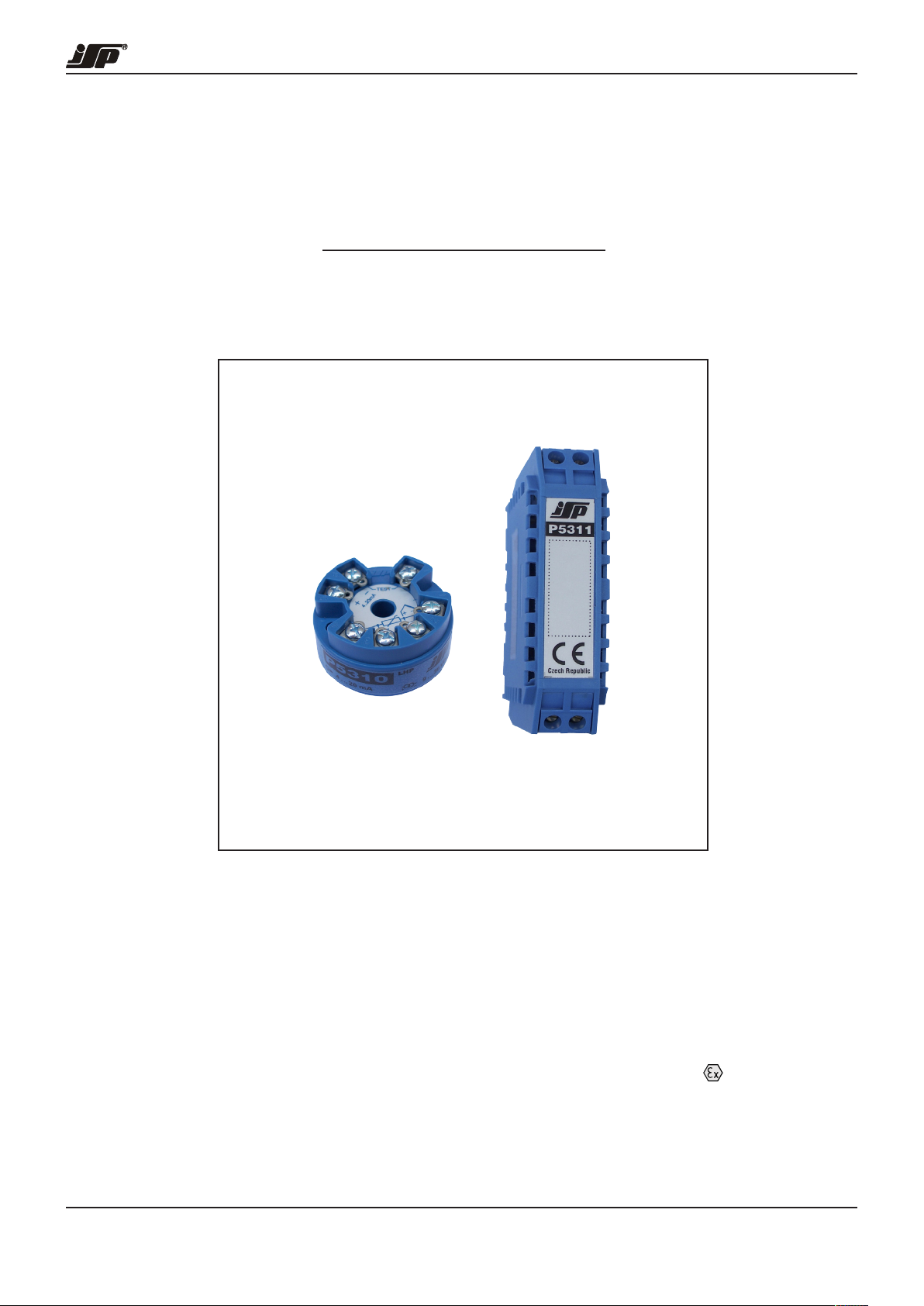
Low-Cost Programmable Transmitters
with LHP Communication
Transmitters - NB0824EN-2 - 2016/04
MANUAL
P5310, P5311
• One type of transmitter for all common resistance
and thermocouple sensors
• Linearized output signal 4 to 20 mA
• Accuracy from 0.1 % for ranges down to 1/5
of the basic range
• Span adjustability from 1 % to 100 %
of the basic range
This document applies to serial numbers 10090000 and higher.
JSP, s.r.o. PHONE / FAX JSP Slovakia s.r.o. PHONE / FAX
Raisova 547 +420 493 760 811 [email protected] Karloveská 63 +421 2 6030 1080 [email protected]
CZ-506 01 Jičín +420 493 760 820 www.jsp.cz SK-841 04 Bratislava +421 2 6030 1089 www.jsp.sk
• Galvanic isolation of input from output
1000 V AC (P5311)
• Adjustability by program LHPWinConf
and standard HART modem or by field
configurator LHPConf (HARTConf)
• High immunity against interference
(industrial environment)
• Intrinsically safe version II 1GD
Page 2

Low-Cost Programmable Transmitters P5310, P5311 with LHP Communication
Contents
1. General instructions and information
1.1 Symbols used ................................................................................................................................................3
1.2 Safety cautions and warnings ........................................................................................................................3
1.3 Scope of delivery ...........................................................................................................................................3
1.4 Description of the delivery and packing ......................................................................................................... 3
1.5 Storage ..........................................................................................................................................................3
1.6 Installation and commissioning ......................................................................................................................3
1.7 Spare parts ....................................................................................................................................................3
1.8 Repairs ..........................................................................................................................................................3
1.9 Warranty .........................................................................................................................................................3
2. End of service and disposal
2.1 End of service ................................................................................................................................................ 3
2.2 Disposal ......................................................................................................................................................... 3
3. Product description
3.1 Application .....................................................................................................................................................4
3.2 Description .....................................................................................................................................................4
3.3 Dimensional drawings ....................................................................................................................................5
3.4 Block diagram ................................................................................................................................................ 5
4. Installation, operation and maintenance
4.1 Installation and commissioning ......................................................................................................................6
4.2 Description of setting and configuration using the communicator LHPWinCom ............................................7
4.3 Description of setting and configuration using a handheld configurator LHPConf or HARTConf ..................7
4.4 Operation and maintenance...........................................................................................................................7
5. Product specifications
5.1 Technical specifications..................................................................................................................................8
5.2 Supplementary parameters ...........................................................................................................................9
6. Tests, certificates and standards
6.1 Tests, certificates ...........................................................................................................................................9
6.2 Standards ......................................................................................................................................................9
6.3 Marking and type tag information ..................................................................................................................9
6.4 Limiting conditions of use of a transmitter in an intrinsically safe version (code EI1) ....................................9
6.5 Limiting conditions of use of a transmitter in version with code EN2 ...........................................................10
7. Ordering information
7.1 Ordering table .............................................................................................................................................. 10
Contacts .............................................................................................................................................................11
- 2 -
Page 3
Low-Cost Programmable Transmitters P5310, P5311 with LHP Communication
1. General instructions and information
1.1 Symbols used
- Warning symbol; for safe use proceed according
to the instructions
- The symbol CE approves conformity of the product
with legal requirements
- Symbol ”Output“
- Symbol “Power supply”
- This product does not belong to public waste
and it is subjected to separate collection
- The product meets requirements for explosion
hazard environment according to the further
specification
LHP - Remote communication protocol for reading
and changing of the configuration
1.2 Safety cautions and warnings
The transmitter shall be powered from a safe voltage
source that meets all requirements of the standard
EN 61010-1 and installed in compliance with national
requirements and standards providing safety.
The equipment may only be installed by a qualified personnel
who are familiar with national and international laws, directives,
standards and with the instructions manual. The instrument
may not be used for other purposes than as specified in this
instructions manual.
For elimination of a risk of injury from electric shock or fire
the maximum operational parameters of the instrument may
not be exceeded, particularly range of operating temperature
because of exposure to heat from connected or surrounding
technological equipment must not be exceeded!
The transmitter should be installed in suitable environment
without any direct sunlight, occurrence of dust, high
temperatures, mechanical vibrations and shocks and protected
against rain and excessive moisture.
1.3 Scope of delivery
With the product is delivered:
- Manual for installation, operation and maintenance
- Certificate of calibration (only with calibrated transmitters)
- Copy of EC certificate on type examination ATEX
(only transmitters for explosion hazard environment)
1.7 Spare parts
Any of the compact parts of the product can be also ordered
as a spare part if there are not required special procedures or
technological operations for the exchange.
1.8 Repairs
Products are repaired by the manufacturer. The products for
repair should be sent with description of the fault or defect in
a packing that guarantees damping of shocks and vibrations
and protects against damage during transport.
1.9 Warranty
Products are covered by a warranty for a period of 3 years
from the delivery date on the delivery note. The manufacturer
guarantees technical and operational parameters of the
products within scope of the applicable documentation.
Warranty period is specified with individual items and begins
from the day of takeover of the goods by the purchaser or
delivery to the carrier. Any claims concerning to defects of the
goods together can be filed in writing with the manufacturer
within the warranty period and the claimed product shall be
presented. The claiming party shall give identification of the
product, number of the delivery note and description of the
fault or defect.
The manufacturer is not responsible for any defects caused
by improper storage, incorrect connection, damages caused
by external effects, in particular by effects of factors with
excessive values, unqualified installation, improper operation
or common wearing.
2. End of service and disposal
2.1 End of service
Dismounting and disposal of the device is possible
after disconnecting of power supply voltage.
2.2 Disposal
The product does not contain any environmentally
harmful parts. When disposing the packing and
destroyed or irreparably damaged product proceed
according to the local regulations.
1.4 Description of the delivery and packing
The product is packaged in a protective cover and provided
with an identification label with a mark of the output control.
The product must not be exposed to direct rain, vibrations and
shocks during transport.
1.5 Storage
The products shall be stored at temperatures from -40 to
+80 °C without condensation of water vapours.
1.6 Installation and commissioning
During installation, commissioning, operation and maintenance
follow the instructions in chapter 4.
- 3 -
Page 4
Low-Cost Programmable Transmitters P5310, P5311 with LHP Communication
3. Product description
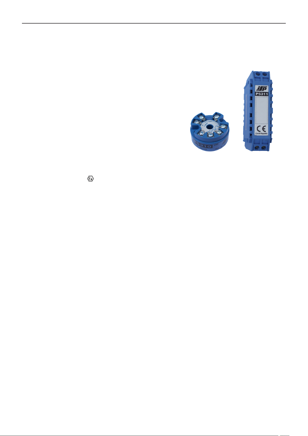
P5310, P5311
Low-Cost Programmable Transmitters
with LHP Communication
• One type of transmitter for all common resistance
and thermocouple sensors
• Linearized output signal 4 to 20 mA
• Accuracy from 0.1 % for ranges down to 1/5
of the basic range
• Span adjustability from 1 % to 100 %
of the basic range
• Galvanic isolation of input from output
1000 V AC (P5311)
• Adjustability by program LHPWinConf
and standard HART modem or by field
configurator LHPConf (HARTConf)
• High immunity against interference
(industrial environment)
• Intrinsically safe version II 1GD
3.1 Application
Transmitters P5310 and P5311 are used for conversion of
a resistance or voltage temperature signal from a resistance
or thermocouple temperature sensor to a linearized current loop
output signal 4 to 20 mA. The transmitter type H1x is designed
for installation into an industrial sensor head type A or B
according to DIN 43729. Inputs and outputs of the transmitters
type P5310 are not galvanic-isolated, these types are suitable
for resistance temperature sensors and simple systems. The
transmitters type P5311 includes galvanic isolation of inputs
and outputs and are suitable for also in applications with many
measuring points and for thermocouples.
3.2 Description
Input signal, switched over according to the input configuration
are processed by an A/D transmitter and transformed into a
digital signal that is transferred to a micro-computer; according
to the preset configuration and after filtration of noise there
are calculated all measured variables. These values are then
used for calculation of the primary variable (temperature)
and according to selected range, the output current is also
calculated.
One resistance sensor (two-, three- or four-wire) can be
connected to the input. In case of a two-wire connection,
entering of a constant value of the loop resistance compensation
during configuration of the transmitter can compensate the
resistance of input leads. In other cases, the leads resistance
is compensated automatically.
A thermocouple can be also connected to the input. Temperature
of the thermocouple cold junction is compensated according
to configuration, either by the inner sensor of terminal block
temperature or by the entered constant temperature. The inner
sensor guarantees maximum accuracy and stability of cold
junction temperature measurement. If required, compensation
using an external sensor can be configured as well.
In addition to standard resistance sensors, there may be also
processed signals of potentiometer positions that are measured
in percents. One limit position is 0 % and the other is 100 %,
independently on the value of the total resistance. In case
there is necessary to measure position of the potentiometer
as a resistance, there may be used the configuration for
measurement of the resistance.
Output of the transmitter is analogue signal of the current loop
4 to 20 mA. The current output can be also used for testing
of the current loop and associated apparatus. Communication
is used mostly for configuration of the transmitter and is not
designed for distances over approx. 10 m. The transmitter can
be set up using a manual configurator LHPConf (HARTConf)
or a PC with the program LHPWinConf and HART modem
HARTMod (MH-02) or equivalent communication interface.
The transmitter communicates through an own protocol LHP
that is partially compatible with the protocol HART, uses the
same connection, however, communication is guaranteed
only for short distances and there are implemented only
few commands. This interface is designed for changes of
configuration. Continuous communication may influence
accuracy of measurement.
- 4 -
Page 5
Low-Cost Programmable Transmitters P5310, P5311 with LHP Communication
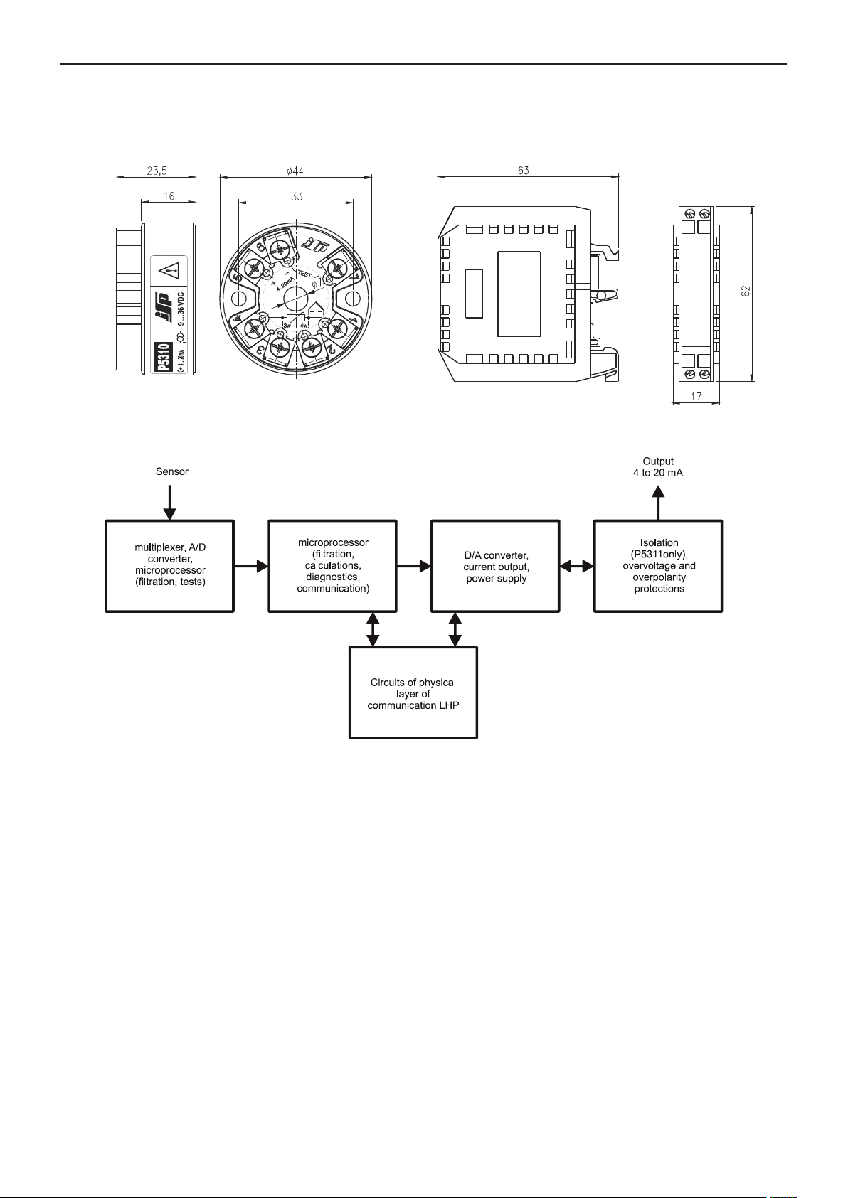
3.3 Dimensional drawings
Version P531x H1x
3.4 Block diagram
Version P531x L1x
- 5 -
Page 6
Low-Cost Programmable Transmitters P5310, P5311 with LHP Communication
4. Installation, operation and maintenance
4.1 Installation and commissioning
4.1.1 General
After mounting and correct connection, switch on the power
supply.
During the installation of transmitters in environment with
higher level of interference, protection of transmitters against
interference and induced overvoltage must be ensured.
According to the standard engineering practice, it is
recommended to separate signal and power wires into
separate gutters and use shielded signal cables with twisted
wires. In case of outdoor wires, it is necessary to solve the
overvoltage protection of the transmitter as a part of overall
solution of protecting system from the effects of atmospheric
electricity.
4.1.2 Special conditions for use of intrinsically safe
version (code EI1)
II 1G Ex ia IIC T4-T6 Ga
II 1D Ex ia IIIC T106°C Da
When installed in explosive environment of gasses or
vapours, the transmitter shall be installed in a metal
case with protection at least IP 20 to avoid electrostatic
charging. Such case may be a metal temperature sensor
head or a suitable metal installation box if it does not contain
aluminium, magnesium, titanium nor zircon. During installation
it is also necessary to respect other safety standards. The
transmitter may be connected on its input and output sides only
to suitable certified associated apparatus or simple apparatus
in the sense of the standard EN 60079-11 with respecting of
the limiting conditions. The transmitter may be installed in an
environment with explosion hazard Zone 0, Zone 1 or Zone
2 only if all the related conditions are fulfilled. The equipment
provides the necessary level of protection during normal
operation and with one or two faults.
When installed in explosive environment of dusts, the
transmitter shall be installed in a metal case to avoid
electrostatic charging. Such case may be a metal temperature
sensor head or a suitable metal installation box if it does not
contain magnesium nor titanium. During installation it is also
necessary to respect other safety standards. The transmitter
may be connected on its input and output sides only to suitable
certified associated apparatus or simple apparatus in the sense
of the standard EN 60241-11 with respecting of the limiting
conditions. The transmitter may be installed in an environment
with explosion hazard Zone 20, Zone 21 or Zone 22 only if all
the related conditions are fulfilled. The equipment provides the
necessary level of protection during normal operation and with
one or two faults.
Galvanic isolation of input and output electrical circuit is not
faulty free isolation in terms of Intrinsically safety and it should
be taken into account during the safety analysis of the system.
4.1.3 Special conditions for using of a transmitter in
version (code EN2)
II 3G Ex nA IIC T4 Gc
The transmitter shall be installed in a metal case with
outlets and protection at least IP 54 (category 1 acc.
to EN 60529) that meets requirement of mechanical
resistance acc. to the standards EN 60079-0 and EN 60079-
15. Such case may be for example the metal temperature
sensor head with protection IP 54 or a suitable installation.
During installation it is also necessary to respect other safety
standards. Output and supply circuits or the transmitter can
be connected only when no voltage is present! In case the
temperature in place of the cable input is higher than 70 °C,
a suitable cable and bushing shall be used and temperature acc.
to par. 16.6 of the standard EN 60079-0 and must be marked
on the outer side of the case! The transmitter may be installed
in an hazardous areas in Zone 2. The equipment provides the
necessary level of protection during normal operation.
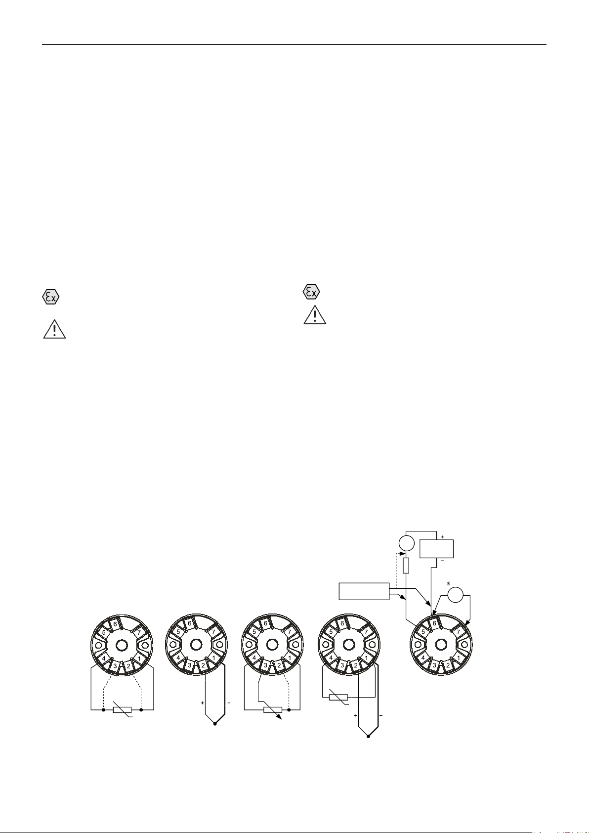
4.1.4 Electrical connection
Version P531x H1x
4w
3w
4w
R TD
OUTPUT
VÝS TU P
~
RL25 0 Ohm
(p ro ko muni kac i)
(for communication)
LHP
LH P k omu ni kát or
Communicator
4w
TC
PO T
R TD
TC
mA
POWER
N AP ÁJE CÍ
ZDR O J
SUPPLY
R
i
TES T
15 Oh m
mA
- 6 -
Page 7
Low-Cost Programmable Transmitters P5310, P5311 with LHP Communication
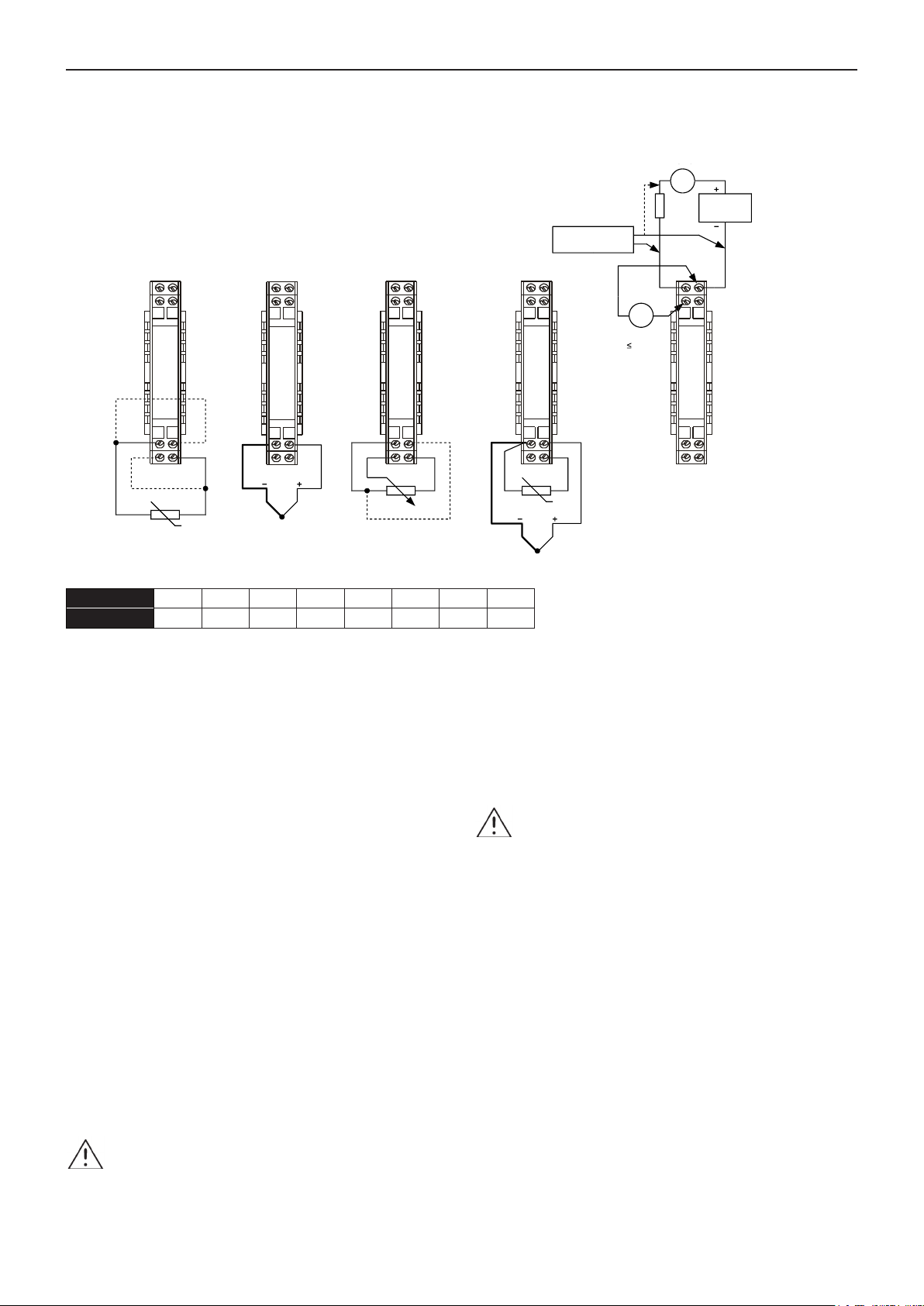
Version P531x L1x
OUTPUT
VÝS TU P
R
25 0 Ohm
~
L
(for communication)
(p ro ko muni kac i)
LHP
LH P k omu ni kát or
Communicator
mA
5
POWER
N AP ÁJE CÍ
ZDR O J
SUPPLY
6
1
3 4
R TD
2
4w
4w
3w
1
3 4
TC
2
1
3 4
PO T
2
4 wir e
Numerals or letters may mark the terminals of the version P531x L1x:
Numerals 1 2 3 4 5 6 7 8
Letters C D A B H G F E
4.2 Description of setting and configuration
using the communicator LHPWinCom
The communicator LHPWinCom consists of program
LHPWinConf, modem HARTMod (MH-02) and connection
cables. Before use is necessary to connect the modem to
a PC using the connection cable, install and run the program
LHPWinConf. Program finds the modem on the respective
4.3 Description of setting and configuration
using a handheld configurator LHPConf or
HARTConf
LHPConf and HARTConf are a field handheld configurators for
setting of all parameters of transmitters with LHP
communication. A detailed description of setting and control is
given in the configurators instruction manual.
communication port by itself. In case, that the program issues a
message that the modem is not connected, enter the respective
port on the HART driver panel.
The program includes two main configuration panels. The
only if the transmitter, configurator and connected wires are
installed out of explosion hazard environment!
panel ”Calibrator Configuration“ is used for fast setting of the
range using a sensor simulator or using a calibrator. The panel
“Keyboard Configuration” allows setting of all the available
transmitter parameters directly on the keyboard without any
necessity to use a calibrator. Individual steps of the optimal
user procedure are given on both panels that should be
followed. Configuration can be saved as a file or print it as a
“Transmitter Configuration Protocol“.
On the panel “Options” you can change the program language
and run the fixed output mode. This mode changes the
4.4 Operation and maintenance
Provided that the instrument is installed correctly, the operator
can read setting and measured values using a configurator.
Setting of the instrument may be changed only if a sudden
change of the output current cannot cause any failure of the
technological equipment or regulation (switch over the possible
regulator to manual control)!
The instrument does not need any maintenance.
transmitter into a simulator of output current with the range
3.5 to 22 mA. In this mode the output current is determined by
the entered value only and is not influenced by changes of the
input quantity. The fixed output mode can be closed by the
program button or by disconnecting of the transmitter power
supply.
Transmitters in version EI1 or EN2 (Ex version) can be
set up using the communicator LHPWinCom only if the
transmitter,
out of explosion hazard environment
communicator and connected wires are installed
!
7 8
1
3 4
R TD
mA
TES T
15 Oh m
R
i
2
TC
Transmitters in version EI1 or EN2 (Ex version) can be
set up using the configurator LHPConf or HARTConf
- 7 -
Page 8

Low-Cost Programmable Transmitters P5310, P5311 with LHP Communication
5. Product specifications
5.1 Technical specifications
Supply voltage:
P5310 9 to 35 VSS
P5311 11 to 35 VSS
Version EI1 11 to 30 VSS
(internally protected against polarity inversion and short term overvoltage)
Range of ambient temperatures: -40 to 85 °C
Reference ambient temperature: 23 ± 5 °C
Housing:
Version H1x IP40, terminals IP00 after
installation to the head the
housing is given by the design
of the head
Version L1x IP20
Humidity:
Version H1x 0 to 100 % RH with condensation
after installation to the head
Version L1x 10 to 80 % RH without
condensation
Connection of wires:
Screw terminals for cross section 0,5 to 1,5 mm2,
torque 0,5 Nm.
Warm-up time: 5 s
Time for re-programming of range using a PC: 5 s
Time for re-programming of sensor type using a PC: 5 s
Type of DIN rail: TS 35 according to DIN 46277
Dimensions (VxŠxH):
H1x Ø 44 x 24 mm
L1x 17.5 x 62.5 x 64 mm
Material of cases:
H1x polycarbonate
L1x polyamide
Weight:
H1x, L1x 40 g
Working position: arbitrary
Input
Input ranges:
Input type Basic range Standard
RTD input 0 to 400 Ohm --RTD input 0 to 4000 Ohm --potentiometer 40 to 400 Ohm --potentiometer 400 to 4000 Ohm --voltage input -15 to 70 mV --Pt100 -200 to 850 °C IEC 60751
Pt500 -200 to 850 °C IEC 60751
Pt1000 -200 to 850 °C IEC 60751
Ni100 -60 to 250 °C DIN 43760
Ni1000 -60 to 250 °C DIN 43760
thermocouple “J“ -200 to 1200 °C IEC 584-1
thermocouple “K“ -200 to 1300 °C IEC 584-1
thermocouple “N“ -200 to 1300 °C IEC 584-1
thermocouple “R“ -50 to 1700 °C IEC 584-1
thermocouple “S“ -50 to 1700 °C IEC 584-1
thermocouple “T“ -250 to 400 °C IEC 584-1
thermocouple “B“ 100 to 1800 °C* IEC 584-1
thermocouple “E“ -200 to 950 °C IEC 584-1
thermocouple “L“ -200 to 900 °C DIN 43710
thermocouple “C“ 0 to 2300 °C N.I.S.T. Monograph
175
* ... range can be set from 0 °C
Digital accuracy:
Input 0 to 400 Ohm ≤ ±0.1% SR or ≤ ±0.08 Ohm
nebo odpovídající teplota
Input 0 to 4000 Ohm ≤ ±0.1% SR or ≤ ±0.8 Ohm
r corresponding temperature
Input -15 to 70 mV ≤ ±0.1% SR or ≤ ±0.02 mV
r corresponding temperature
(the greatest value is valid; SR ... Span of set range
accuracy of measured value of digital output LHP)
Input signal:
Resistance signal of temperature sensor or
potentiometer, voltage signal of thermocouple
Sensor connection:
Resistance sensor two-, three-, four-wire
Voltage sensor (TC) two-wire
Potentiometer three-wire or four-wire
Compensation using
an external sensor two-wire
Maximum wire resistance for resistance ranges: :
< 20 Ohm (each wire)
Current through resistance sensor:
< 0.15 mA
Input overloading:
Max. 24 VDC or max. 18 mA between any inputs
(max 60 s)
Cold junction compensation error: < ±1 °C
Effect of wire resistance for resistance ranges:
Two-wire connection can be compensated by
constant value
Three-wire connection no effect with identical
values of wire resistance
Four-wire connection no effect with specified
wire resistance range
Input resistance: > 10 MOhm
Output
Output signal:
Two-wire 4 to 20 mA or 20 to 4 mA
Total measurement error on the analogue output of P5310
Range 0 to 400 Ohm ≤ ±0.1% SR or ≤±0.08 Ohm
or corresponding temperature
Range 0 to 4000 Ohm ≤ ±0.1% SR or ≤ ±0.8 Ohm
or corresponding temperature
Range -15 to 70 mV ≤ ± .1% SR or ≤ ±0.02 mV
or corresponding temperature
Range Pt100, Pt1000, Ni100, Ni1000
≤ ±0.1 % SR or ≤ ±0.2 °C
Range Pt500 ≤ ±0.1 % SR or ≤ ±0.4 °C
Range TC J, K, T, E, L typ. ≤± 0.1 % SR or 0.5 °C
Range TC R, S, B, C typ. ≤± 0.1 % SR or 2 °C
(the greatest value is valid)
:
- 8 -
Page 9

Low-Cost Programmable Transmitters P5310, P5311 with LHP Communication
Total measurement error on the analogue output of P5311:
Range 0 to 400 Ohm ≤ ±0.15% SR or ≤ ±0.12 Ohm
or corresponding temperature
Range 0 to 4000 Ohm ≤ ±0.15% SR or ≤ ±1.2 Ohm
or corresponding temperature
Range -15 to 70 mV ≤ ±0.15% SR or ≤ ±0.03 mV
corresponding temperature
Range Pt100, Pt1000, Ni100, Ni1000
≤ ±0.15 % SR or ≤± 0.3 °C
Range Pt500 ≤ ±0.15 % SR or ≤± 0.6 °C
Range TC J, K, T, E, L typ. ≤± 0.15 % SR or 0.5 °C
Range TC R, S, B, C typ. ≤± 0.15 % SR or 2 °C
(the greatest value is valid)
Characteristics:
Linear with temperature or linear with input quantity,
other upon request
Adjustability of the range:
±1% to ±100% of the input range
Adjustability:
Inside the input range (the given measurement errors
apply for suppression of the beginning ≤ 100% of the
range)
Time constant (95 %):
Adjustable 0.5 to 60 s (2 measurements per second)
Load resistance: RL [Ohm] ≤ (UN [V] - 9) / 0.022
Electric strength of galvanic isolation of P5311:
1000 VAC (test)
Isolation resistance of galvanic isolation of P5311:
Min. 100 MOhm
5.2 Supplementary parameters
Output current limitation:
Signal 3.8 to 20.5 mA acc. to NAMUR NE43
Limitation of error current to approx. 22 mA
Indication of sensor or transmitter error:
Optionally by current > 21 mA or < 3.6 mA
according to NAMUR NE43
Supply voltage effect: ≤ ±0.005 % / V
Influence of ambient temperature changes:
Range 0 to 400 Ohm (≤ ±0.1% SR or ≤ ±0.08 Ohm
or corresponding temperature) / 10 °C
Range 0 to 4000 Ohm (≤ ±0.1% SR or ≤ ±0.8 Ohm
or corresponding temperature) / 10 °C
Range -15 to 70 mV (≤ ±0.1% SR or ≤ ±0.02 mV
or corresponding temperature) / 10 °C
(the greatest value is valid)
Long-term stability:
≤ ±0.1 % of the preset range per 2 years
Electromagnetic compatibility:
Radiation and immunity acc. to EN 61326-1
(Industrial environment)
MV ... measured value
SR ... span of preset range
6. Tests, certificates and standards
6.1 Tests, certificates
Electromagnetic compatibility
Emission and immunity acc. to EN 61326-2-3
Intrinsically safe version (option EI1)
Certificate
Version “n“ (version EN2)
Producer assessment ZV100006 (P5311) and ZV100011
(P5310)
FTZÚ 06 ATEX 0353X + Supplements 1, 2 and 3
6.2 Standards
Transmitter is designed and manufactured according these
standards:
EN 61010-1
Version EI1:
EN 60079-0
EN 60079-11
EN 60079-26
Version EN2:
EN 60079-0
EN 60079-15
6.3 Marking and type tag information
Standard version:
Standard version:
P5311 type number
Model: version
S/No: serial number
Czech Republic country of origin
logo of JSP, s.r.o.
www.jsp.cz contact for manufacturer
Tag of version EI1 includes further:
II 1G Ex ia IIC T4-T6 Ga
II 1D Ex ia IIIC T106°C Da
year of manufacture
number of ATEX certificate
Tag of version EN2 includes further:
II 3G Ex nA IIC T4 Gc
-40 °C ≤ Ta ≤ 85 °C
year of manufacture
document number of producer assessment report
6.4 Limiting conditions of use of a transmitter
in an intrinsically safe version (code EI1)
Relation between the temperature class and ambient
temperature:
T4 (T106 °C) -40 °C < T
T5 (T76 °C) -40 °C < T
T6 (T61 °C) -40 °C < T
< 85 °C
amb
< 55 °C
amb
< 40 °C
amb
- 9 -
Page 10

Low-Cost Programmable Transmitters P5310, P5311 with LHP Communication
Wall mounted box (170x145x85 mm), housing IP 55 (for L1x versions, not for EI1, EN2)
Wall mounted box (100x100x58 mm), housing IP 65 (for H1x versions, not for EI1, EN2)
•••
•
•
Output (current loop, terminal 5 and 6):
U
I
P
L
C
Output test (terminal 6 and 7; it is designed only for temporary
= 30 VDC
i
= 100 mA
i
= 0.9 W
i
= 350 µH
i
= 0 nF
i
connection of a multimeter):
U
I
P
L
C
= 30 VDC
o
= 100 mA
o
= 0.9 W
o
= 100 µH
o
= 0 nF
o
Input for a sensor:
U
I
P
L
C
= 6.6 VDC
o
= 21 mA
o
= 0.034 W
o
= 70 mH
o
= 1 µF
o
For other conditions see paragraph 4.1.2.
6.5 Limiting conditions of use of a transmitter
in version with code EN2
See paragraph 4.1.3.
7. Ordering information
7.1 Ordering table
Type Description
P5310 Low-cost programmable transmitter with LHP protocol without galvanic isolation (accuracy 0,1 %)
•
P5311 Low-cost programmable transmitter with LHP protocol with galvanic isolation (accuracy 0,15 %)
•
Code
H10
•
H11
•
L10
•
L11
•
Code
NR Without requirements for the range and input setting (preset - Pt100, three-wire connection of sensor, 0 to 100 °C)
•
QR
•
Code Calibration
KPP5 Transmitter calibration in five points evenly distributed in setting range
Kód
EI1 Intrinsically safe version (Ex) II 1G Ex ia IIC T4-T6 Ga, (Ex) II 1D Ex ia IIIC T106°C Da (only for version P5311 H1x)
EN2 Non-incendive design (Ex) II 3G Ex nA IIC T4 Gc
Code
LHPWinCom Set of configuration program LHPWinConf (CZ+EN) for PC and modem HARTMod
LHPConf
HARTConf HART-USB modem and field communicator for LHP and HART transmitters, function of transmitter supply
HARTMod Miniature HART modem with galvanic isolation
USB-RS232C Communication interface for to USB port of the PC
•
PT1000A Compensation resistor Pt1000 (-30 to +150 °C) for external compensation of thermocouple
•
S51 Box for wall mounting of one transmitter to explosive atmosphere (IP 68)
S52 Box for wall mounting of one transmitter with LED display to explosive atmosphere (IP 68)
S54
S55
S56
VH1 Cap for head form B for transmitter mounting (for H1x versions)
APT1 Adapter for flat head
KME1 Cable outlet, nickel silver, Ex d, M20x1.5, IP 68, for fixed assembly cable with diameter 4 to 8.5 mm
KME2 Cable outlet, nickel silver, Ex d, M20x1.5, IP 68, for fixed assembly cable with diameter 6 to 12 mm
KME3 Cable outlet, stainless steel, Ex d, M20x1.5, IP 68, for fixed assembly cable with diameter 4 to 8 mm
KME5 Cable outlet, polyamide, Ex ie, M20x1.5, IP 68, for fixed assembly cable with diameter 5 to 9 mm, operating temperature -20 to +95 °C
KME6 Cable outlet, polyamide, Ex ie, M20x1.5, IP 68, for fixed assembly cable with diameter 6.5 to 12 mm, operating temperature -20 to +95 °C
Example of order: P5311 H11 QR For code QR configuration sheet DB2298 is required to the order.
Version
Into head B according to DIN, universal for resistance sensors and thermocouples
Into head B according to DIN, only for resistance sensors
On the rail TS 35, universal for resistance sensors and thermocouples
On the rail TS 35, only for resistance sensors
Setting requirements
Range and other parameters setting according to configuration sheet DB2298
Optional version
Optional accessories
Field configurator for LHP transmitters, function of transmitter supply, without charging
supplied from USB or inbuilt accumulator, charged from USB
(Ex) II 2G Ex d IIC T6, T5 Gb + (Ex) II 2D Ex t IIIC T50/60/80°C Db (2 cable glands KMEx have to be ordered)
(Ex) II 2G Ex d IIC T6, T5 Gb + (Ex) II 2D Ex t IIIC T50/60/80°C Db (2 cable glands KMEx have to be ordered)
Wall mounted box (100x100x58 mm), housing IP 65 (for H1x versions, not for EI1, EN2)
• ... Ex stock version ° ... Marked version can be dispatched up to 5 working days (with calibration up to two weeks)
1)
… Possibility of installing one transmitter
3)
… Possibility of installing two transmitters
2)
… Possibility of installing up to three transmitters
1)
2)
3)
3-year warranty
- 10 -
Page 11

JSP Industrial Controls
JSP, s.r.o.
Raisova 547, 506 01 Jičín, Czech Republic
+420 493 760 811 | [email protected] | www.jsp.cz
Your Supplier:
 Loading...