


DC2010
Data Center
User’s Manual (V1.0)
健昇科技股份有限公司
JS AUTOMATION CORP.
新北市汐止區中興路 100 號 6 樓
6F., No.100, Zhongxing Rd.,
Xizhi Dist., New Taipei City, Taiwan
TEL:+886-2-2647-6936
FAX:+886-2-2647-6940
http://www.automation.com.tw
http://www.automation-js.com/
E-mail:control.cards@automation.com.tw

Version Record
1.0
Correction record
1

Contents
1 Introduction..........................................................................................................................................4
1.1 Package contents......................................................................................................................4
2 Install hard disks..................................................................................................................................5
3 Hardware installation...........................................................................................................................8
3.1 Connecting to a single PC........................................................................................................8
3.2 Connecting to be accessible from Internet...............................................................................9
3.3 Connecting the power..............................................................................................................9
3.4 Connecting to UPS...................................................................................................................9
4 Configuration through front panel.....................................................................................................10
4.1 Familiar with the front panel operation.................................................................................10
4.2 How to operate the touch wheel ............................................................................................11
4.3 First boot up...........................................................................................................................13
4.4 System creation......................................................................................................................14
4.5 Entering parameter editing mode...........................................................................................15
4.6 System information from local panel.....................................................................................17
4.7 LCD backlight setting from local panel.................................................................................18
4.8 Screensaver time setting from local panel.............................................................................18
4.9 Network setting from local panel...........................................................................................19
4.10 USB backup setting from local panel ....................................................................................21
4.11 Selection of input method......................................................................................................22
4.12 Password change setting from local panel.............................................................................23
4.13 Create system setting from local panel..................................................................................24
4.14 Restore system setting from local panel ................................................................................24
4.15 System restart setting from local panel..................................................................................25
4.16 Shutdown DC2010 from local panel .....................................................................................25
4.17 AUTO shut down by UPS power lost....................................................................................26
5 Introduction to web storage manager.................................................................................................27
6 System information from web storage manager................................................................................29
6.1 Login the administration page ...............................................................................................29
6.2 System -> Overview..............................................................................................................30
6.3 System -> Summary ..............................................................................................................31
7 System management from the web storage manager.........................................................................32
7.1 System Manager -> Date and Time .......................................................................................32
7.2 System Manager -> Network.................................................................................................35
7.3 System Manager -> Language...............................................................................................37
7.4 System Manager -> Administrator.........................................................................................38
7.5 System Manager -> Disk Manager........................................................................................39
7.6 System Manager -> DDNS....................................................................................................40
8 Access Right Management from the web storage manager...............................................................41
2

8.1 Access Right Management -> Group management...............................................................41
8.2 Access Right Management -> User management..................................................................43
8.3 Access Right Management -> File Sharing...........................................................................47
9 System service...................................................................................................................................51
9.1 System Service -> FTP Service.............................................................................................51
9.2 System Service -> iTunes Service.........................................................................................52
9.3 System Service -> Backup.....................................................................................................54
9.4 System Service -> Log file....................................................................................................58
10 Application.....................................................................................................................................60
10.1 BitTorrent...............................................................................................................................60
10.2 Downloader............................................................................................................................65
11 System update....................................................................................................................................67
3
1 Introduction
Thank you for purchasing the DC2010 data center. This device is network attached file server
(NAS) with RAID1 auto backup. The operating system is a customized Linux based OS, which stored at
on board flash. For the ultimate safety, the power of the hard disks is separately powered.
This manual will bring you go through the detail operation of the device, from device connection,
local panel configuration and remote web configuration then the applications provided with the device.
You need some knowledge of the internet such as IP, TCP, hub, router, gateway. We will reference them
and make a brief explanation as required, if you want to know more detail please refer any web site that
supplies such kind knowledge.
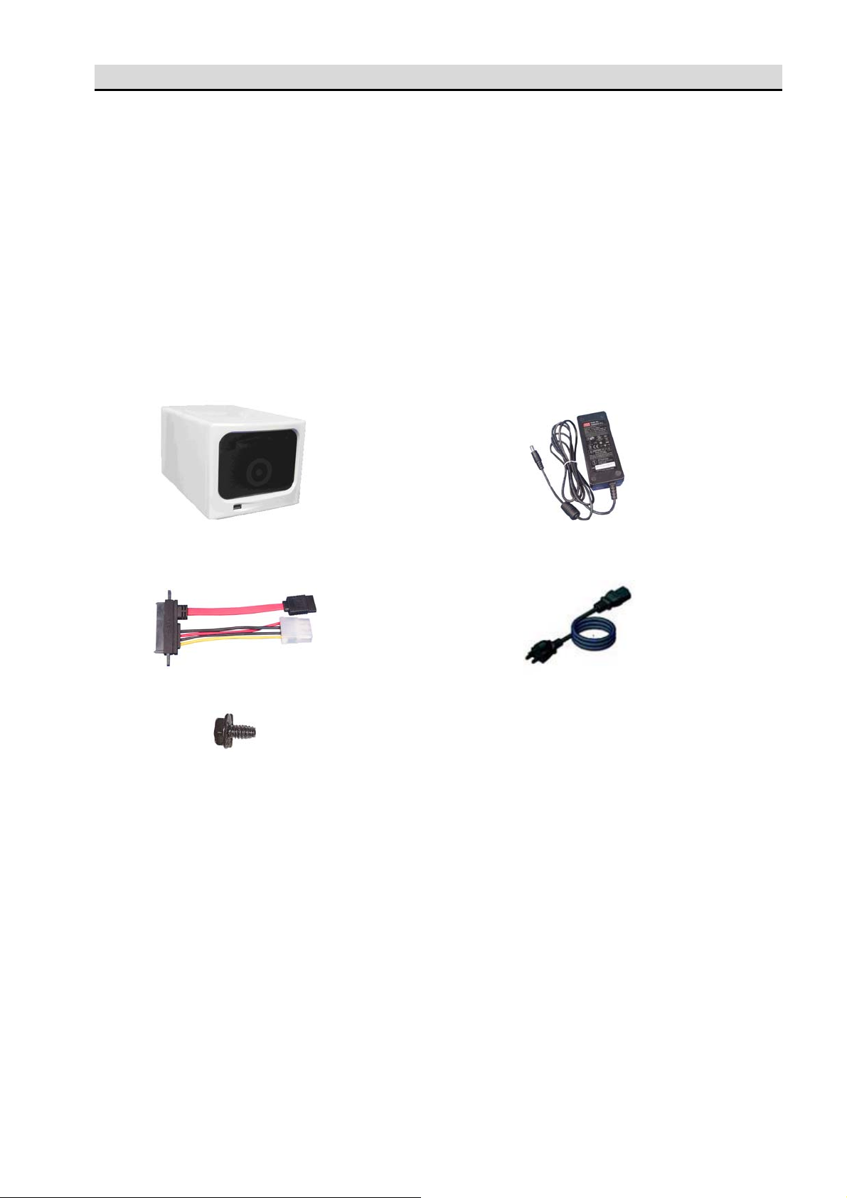
1.1 Package contents DC2010 *1 Power adaptor *1: 110/220Vac to 24Vdc
Hard disk cables *2 Power cord *1
Hard disk fixing screws *8
4

2 Install hard disks
Slide out the rack
1. Un-screw the screws as red circle shown.
2. Pull to slide out the rack from cover.
5
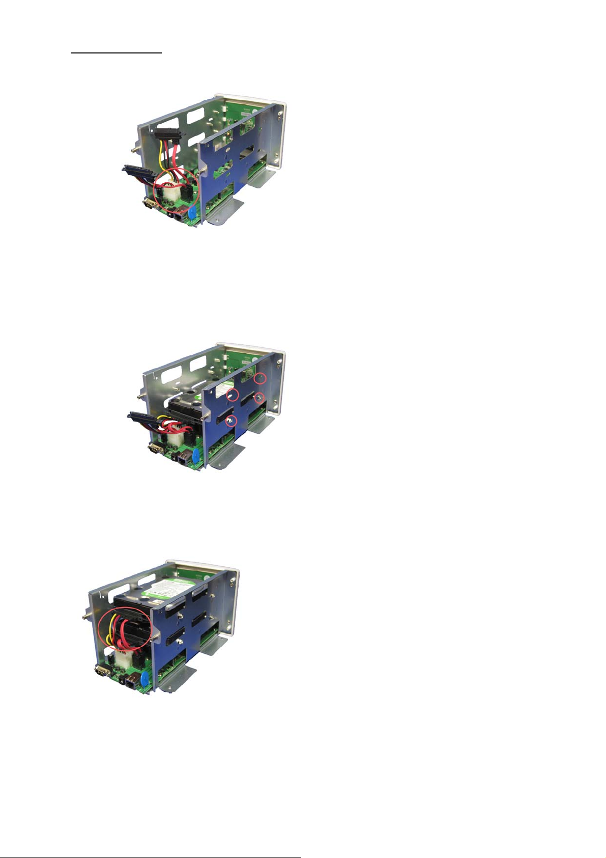
Install hard disks
3. Install the hard disk power and control cables
4. Screw to fix the hard disks.
5. Install the cables to the hard disks
6

Re-cover the device
6. Slide in the rack to the cover
7. Screw the bottom screws
8. Screw the rear panel screws
7

3 Hardware installation
1. RS232: UPS communication connector
2. Power connector: +24Vdc power input connector
3. RJ45: Ethernet connector
3.1 Connecting to a single PC
DC2010 may work as an external safe storage of your PC, if you connect the DC2010 to your PC
only. In this environment, you cannot share files through network with others.
8

3.2 Connecting to be accessible from Internet
If your want to share files with others or you want to access files from anywhere provided Ethernet,
you must have an IP which is external accessible. The most possible configuration is as follows.
You need a gateway to control the external and internal message flow, and hub to switch the
intranet message flow. Currently on the market a ‘router’ will act as gateway and hub.
Please refer the gateway’s or router’s manual to configure your environment.
3.3 Connecting the power
If you use a UPS, please connect the power adaptor input power cord to the UPS output socket. If
you do not use the UPS, connect the input power cord to the power socket available. The power adaptor
comes with the DC2010 is a universal type; the power source may be 100/110Vac or 200/220Vac at
50/60 Hz. Then connect the adaptor output to DC2010 rear connector 24Vdc input.
3.4 Connecting to UPS DC2010 has designed in UPS communication protocol with OPTI_UPS model VS375C. Connect
the DC2010 rear D type 9pin connector to the UPS 9 pin connector with standard RS232 cable. When
the power is lost, the UPS will inform the DC2010 to safely shut down; then if power recovered, the
UPS will inform the DC2010 to auto boot.
9

4 Configuration through front panel
4.1 Familiar with the front panel operation
1. HDD: hard disk active indicator
2. UPS: UPS active indicator, when the rear RS232 connector successfully connect to OPTI-UPS
VS375C, the indicator will light.
3. ACT: ACT indicator flicks while power on but the DC2010 not active. While the device is
activated, the ACT will light.
4. LAN: Ethernet active connector, when the rear RJ45 Ethernet connects successfully.
5. LCD message display: display the information.
6. USB connector: USB2.0 connector for local USB backup.
7. Touch wheel: Thumb touch and slide to select displayed items.
8. Confirm button: Touch button for confirmation.
10

4.2 How to operate the touch wheel Before we use touch wheel and confirmation button to input or correct the digits, let us take a brief
trip about the operation. There are two possible manual touch methods, rotate wheel or touch click. The
default is rotate wheel input method.
If the input is touch wheel, please refer the followings:
Touch wheel input method:
1. There are 2 cursors on the screen; the top lane cursor is the input cursor, the lower lane cursor is
the candidate cursor.
2. The cursor highlighted input digit is the digit available to input.
3. Touch the wheel and rotate right, the cursor on candidate digit will jump right.
4. Touch the wheel and rotate left, the cursor candidate digit will jump left.
5. ← Left shift: shift left the input space cursor.
6. → Right shift: shift right the input space cursor.
7. ↵ Confirm: confirm the input data
8. ↑ Return to upper level
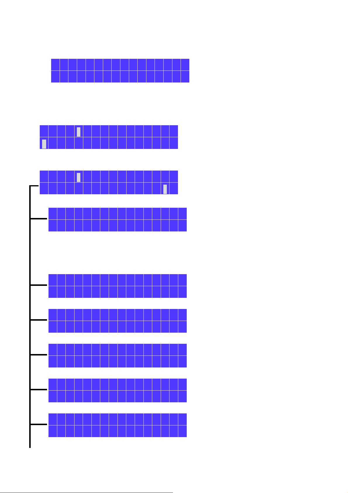
Try an example of input; if the LCD message is on password input page, the device now is waiting
for your input.
P W D : _ _ _ _ _ _
0 1 2 3 4 5 6 7 8 9 ← → ↵ ↑
Say the password is 123456 (note that: the factory default is 000000), the process you will go:
A. Press the wheel and rotate the wheel to jump the candidate cursor to digit ‘1’ then press the
confirmation button to enter the first digit while input cursor on first digit.
B. Press the wheel and rotate the wheel to jump the candidate cursor to digit ‘2’ then press the
confirmation button to enter the second digit while input cursor on second digit.
C. Repeat the process until all the digits are input.
D. Move the candidate cursor to confirm, press confirmation button to input data to the device.
E. If you want to change any digit already input, rotate the touch wheel to move candidate
cursor to left shit or right shift and press confirmation button to shift the input cursor to the
digit you want to change. Input the new digit as process described above.
11

If the input method is touch click, refer the followings:
Touch click input method:
1. There are 2 cursors on the screen; the top lane cursor is the input cursor, the lower lane cursor is
the candidate cursor.
2. The cursor highlighted input digit is the digit available to input.
3. Touch the wheel left half ring; the cursor candidate digit will jump left.
4. Touch the wheel right half ring; the cursor candidate digit will jump left.
5. ← Left shift: shift left the input space cursor.
6. → Right shift: shift right the input space cursor.
7. ↵ Confirm: confirm the input data
8. ↑ Return to upper level ↵
Try an example of input; if the LCD message is on password input page, the device now is waiting
for your input.
P W D : _ _ _ _ _ _
0 1 2 3 4 5 6 7 8 9 ← → ↵ ↑
Say the password is 123456 (note that: the factory default is 000000), the process you will go:
A. Press the wheel ring left or right to jump the candidate cursor to digit ‘1’ then press the
confirmation button to enter the first digit while input cursor on first digit.
B. Press the wheel ring left or right to jump the candidate cursor to digit ‘2’ then press the
confirmation button to enter the second digit while input cursor on second digit.
C. Repeat the process until all the digits are input.
D. Move the candidate cursor to confirm, press confirmation button to input data to the device.
E. If you want to change any digit already input, click the touch wheel to move candidate
cursor to left shit or right shift and press confirmation button to shift the input cursor to the
digit you want to change. Input the new digit as process described above.
We will use the touch wheel as default configuration, any terms mentioned as rotate wheel
right or left is equivalent to click right or left.
12

4.3 First boot up When power on, the front panel ACT indicator will be flicking to indicate power on but DC2010
not working. To start the DC2010 press the confirmation button more than 3 s. The LCD will display the
welcome message as follows:
D a t a C e n t e r
J S A u t o m a t i o n
S y s t e m B o o t i n g
> > >
Normally the system will be ready to serve within 2 minutes. After the system boot up, there are
two possible situations will be:
A. If first time boot up and hard disk have never formatted. The system will request to create
system.
C r e a t e S y s t e m
← →
(Welcome message)
(System booting…)
B. If the system has already created and no error occurs, the message will be the IP you set. (in this
example the IP is : 192.168.0.168)
D C - 2 0 1 0
1 9 2 . 1 6 8 . 0 . 1 6 8
13
4.4 System creation
System creation will erase the data already on the hard disk and copy the operating system to hard
disk.
At first boot up system requires creating system. If system failure or manually request to create
system, you must make sure if you want to discard the data or you have data backed up somewhere.
The default configuration of the system is RAID1, we strongly recommended to use 2 disks of the
same model.
C r e a t e S y s t e m
If YES, confirm to create system
Proceed to verify the hard disks
If hard disk error, power off and try to re-install them
If hard disk is OK, create system with RADI1 as default.
← →
System creation
C r e a t e ?
Y e s ■ N o
C h e c k D e v i c e
> > > > > > >
D e v i c e E r r o r
C h e c k a n d R e r u n
C r e a t i n g R A I D 1
> > > > >
I n i t i a l S u c c e s s
If system create OK, the system will auto re-boot.
System re-start information.
Make confirmation, if you really want to re-boot
S y s t e m R e s t a r t
← →
I t w i l l r e s t a r t
Y e s ■ N o
I t w i l l r e s t a r t
14
4.5 Entering parameter editing mode
When the system boot up and the hard disks are also in good condition, the LCD will display the
device name and IP (at the first time boot up, the IP will be the default IP). Shown as follows:
D C - 2 0 1 0
1 9 2 . 1 6 8 . 0 . 1 2 0
Now the device is waiting for manual input to configure from panel. With the touch wheel and
touch confirmation button, you can go through all the basic settings.
Touch the confirmation button more than 3 seconds to activate the setting message:
P W D : _ _ _ _ _ _
0 1 2 3 4 5 6 7 8 9 ← → ↵ ↑
Input the password (default is 000000, 6 zeros), if you forget pass word, please keep
the confirmation button touched for more than 3 s to restore the default password.
P W D : * * * * * *
0 1 2 3 4 5 6 7 8 9 ← → ↵ ↑
Select confirm to input data to DC2010
P a s s w o r d E r r o r
P l e a s e T r y A g a i n
If password error, try again.
If password correct, the system entering parameter editing mode.
Rotate the touch wheel, you can go through each page and select the desired page
by confirmation button to enter the mode.
S y s t e m S u m m a r y
← →
Display system information
L C D B a c k l i g h t
← →
Adjust and setting the LCD backlight
S c r e e n s a v e r t i m e
← →
Adjust the LCD screen saver time
N e t w o r k S e t t i n g
← →
Ethernet settings
U S B B a c k u p
← →
External USB backup
15
S e l e c t i o n M e t h o d
← →
Touch wheel rotate or click mode
P a s s w o r d C h a n g e
← →
Change password of manual panel
C r e a t e S y s t e m
← →
New system generation or re-format the hard disk
R e s t o r e S e t t i n g
← →
restore system setting
R e t u r n M a i n
← →
Go back to top layer of menu
S y s t e m R e s t a r t
← →
DC2010 restart
A u t o D e m o
← →
Demonstrate the setting procedures
16
4.6 System information from local panel
S y s t e m S u m m a r y
← →
Use touch wheel and confirmation to enter system parameter editing mode.
Touch the confirmation button to proceed with the information.
D e v i c e N a m e
D C 2 0 1 0
Display device name, default is DC2010 but you can modify to your preferred
through web API program. Touch confirmation button for next message.
F i r m w a r e
V 1 . 0
Firmware version. Touch confirmation button for next message.
T o t a l C a p c i t y
9 2 8 G B y t e
Total disk capacity (depends on the disk size).
Touch confirmation button for next message.
U s a g e
2 2 M B y t e ( 1 % )
Display the disk usage. (depends on disk).
Touch confirmation button will jump to ‘System Summary’ screen.
17

4.7 LCD backlight setting from local panel
Right shift the touch wheel until ‘Screensaver time’ displayed.
L C D B a c k l i g h t
← →
Now you’re in LCD back light setting sub-function, touch confirmation button to
choose it. And the screen will enter ‘Time’ setting.
B r i g h t n e s s
- ← 9 → +
Rotate the touch wheel to choose the normal backlight you want then touch the
confirmation button to return upper level.
4.8 Screensaver time setting from local panel
Right shift the touch wheel until ‘Screensaver time’ displayed.
S c r e e n s a v e r t i m e
← →
Now you’re in Screensaver time setting sub-function, touch confirmation button to
choose it. And the screen will enter ‘Time’ setting.
T i m e : 0 6 0 s e c
0 1 2 3 4 5 6 7 8 9 ← → ↵ ↑
Enter time constant you want then rotate the touch wheel to choose confirm to
return upper level.
18
4.9 Network setting from local panel
In system parameter editing mode, right shift the touch wheel until ‘Network Setting’
displayed.
N e t w o r k S e t t i n g
← →
Now you’re in network setting sub-function, touch confirmation button to choose
it. And the screen will enter ‘Network Mode’ setting.
N e t w o r k M o d e
D H C P ■ S t a t i c ↑
If your device will be assigned IP by DHCP, choose it by rotate the touch wheel
to move the cursor on it then touch the confirmation button, the screen will
display ‘Network restart’ for a while then return to ‘Network Setting’.
If you will assign static IP, move the cursor on it then touch the confirmation
button.
If your choice is static IP, the screen will display the previous setting.
D a t a C e n t e r I P
1 9 2 . 1 6 8 . 0 . 1 6 8
Touch the confirmation button to enter data entry mode.
1 9 2 . 1 6 8 . 0 0 0 . 0 0 7
0 1 2 3 4 5 6 7 8 9 ← → ↵ ↑
Use touch wheel and confirmation button to enter the data
1 9 2 . 1 6 8 . 0 0 0 . 0 0 7
0 1 2 3 4 5 6 7 8 9 ← → ↵ ↑
Select the confirm icon and touch the confirmation button to set DC2010
D a t a C e n t e r I P
1 9 2 . 1 6 8 . 0 . 7
Now return the upper level and new IP displayed, rotate touch wheel to next
item.
N e t m a s k
2 5 5 . 2 5 5 . 2 5 5 . 0
Touch confirmation button to enter data entry mode.
2 5 5 . 2 5 5 . 2 5 5 . 0 0 0
0 1 2 3 4 5 6 7 8 9 ← → ↵ ↑
Enter the net mask of your network and confirm to return upper level (net
mask display) then rotate touch wheel to ‘Gateway’ display.
G a t e w a y
1 9 2 . 1 6 8 . 0 . 1
19
Touch confirmation button to enter data entry mode.
1 9 2 . 1 6 8 . 0 0 0 . 0 0 1
0 1 2 3 4 5 6 7 8 9 ← → ↵ ↑
Enter the gateway IP of your network and confirm to return upper level
(gateway display) then rotate touch wheel to ‘DNS Server’ display.
D N S S e r v e r
1 6 8 . 9 5 . 0 . 1
Touch confirmation button to enter data entry mode.
1 6 8 . 0 9 5 . 0 0 0 . 0 0 1
0 1 2 3 4 5 6 7 8 9 ← → ↵ ↑
Enter the DNS IP of your network and confirm to return upper level ( DNS
Server display) then rotate touch wheel to ‘Other DNS Server’ display.
O t h e r D N S S e r v e r
1 6 8 . 9 5 . 1 9 2 . 1
Touch confirmation button to enter data entry mode.
1 6 8 . 0 9 5 . 0 0 1 . 0 0 1
0 1 2 3 4 5 6 7 8 9 ← → ↵ ↑
Enter the other DNS IP (if you only want to use the primary one, input
0.0.0.0 to other DNS IP) of your network and confirm to return upper level
(other DNS Server display) then rotate touch wheel to ‘Return’ display.
R e t u r n
Touch confirmation button to update the setting of DC2010.
N e t w o r k R e s t a r t
> > > > >
20

4.10 USB backup setting from local panel
USB back up function can be used for copy files from USB to DC2010 directly.
All the files on USB will copy to DC2010.
Right shift the touch wheel until ‘Backup from USB’ displayed.
U S B B a c k u p
← →
Now you’re in USB backup sub-function, touch confirmation button to choose it.
B a c k u p F r o m U S B
Y e s ■ N o
Choose Yes to confirm USB backup.
B a c k u p
> > > > >
Backup is proceeding.
B a c k u p S u c c e s s
If copy from USB to DC2010 is successful, touch confirmation button to back
to upper level.
N o D e v i c e
P l e a s e T r y A g a i n
If no device or device error, try again.
21

4.11 Selection of input method
Selection method provide the possible input method: rotate wheel or touch click input
method
S e l e c t i o n M e t h o d
← →
Now you’re in input method selection sub-function, touch confirmation button to
choose it.
S e l e c t M o d e
W h e e l ■ C l i c k
Choose rotate wheel or touch click method you want then touch confirm button
S e l e c t i o n M e t h o d
← →
22

4.12 Password change setting from local panel
Right shift the touch wheel until ‘Password Change’ displayed.
P a s s w o r d C h a n g e
← →
Now you’re in password change sub-function, touch confirmation button to choose
it.
N e w P W D : _ _ _ _ _ _
0 1 2 3 4 5 6 7 8 9 ← → ↵ ↑
Rotate the touch wheel to input data then choose confirm and touch confirmation
button to enter. The screen will prompt to request the confirmation input.
C o n f i r m : _ _ _ _ _ _
0 1 2 3 4 5 6 7 8 9 ← → ↵ ↑
Input password data to re-confirm.
K e y i n E r r o r
P l e a s e T r y A g a i n
If the first input data do not confirm with the second input, error to request
retry.
P a s s w o r d C h a n g e
← →
If no error the password has changed and automatically return to item
selection level.
23

4.13 Create system setting from local panel
Create System will destroy all the data already on the device. Please make sure you
have backup copy or you will discard the data else do not try this function.
C r e a t e S y s t e m
← →
Right shift the touch wheel until ‘Create System’ displayed.
I t w i l l r e s t a r t
Y e s ■ N o
If you choose No, the display will return to upper level function.
If you choose Yes, the system will restart then enter the system create function just
as the first time system creation.
Create system will destroy all the data already on the disk.
4.14 Restore system setting from local panel
Restore setting will restore the default from flash memory to hard disk (include
password and web page).
Right shift the touch wheel until ‘Restore Setting’ displayed.
R e s t o r e S e t t i n g
← →
Now you’re in Restore Setting sub-function, touch confirmation button to choose it.
R e s t o r e
Y e s ■ N o
?
Choose Yes to confirm USB backup.
R e s t o r i
> > > > >
n g
Restore is proceeding. It need about 20s to restore.
24
4.15 System restart setting from local panel
Right shift the touch wheel until ‘System restart’ displayed.
S y s t e m R e s t a r t
← →
Now you’re in System Restart sub-function, touch confirmation button to choose it.
I t w i l l r e s t a r t
■ Y e s N o
Rotate the touch wheel to choose what you want then touch the confirmation
button to take action.
4.16 Shutdown DC2010 from local panel
From the default system display:
D C - 2 0 1 0
1 9 2 . 1 6 8 . 0 . 1 2 0
Press the confirmation button to shutdown the device.
S h u t d o w n
> > > > >
Now you’re UPS auto shut down mode, it will auto re-boot while UPS re-powered.
T o t u r n O N
K e e p b u t t o n p r e s
Now system is shutting down, if complete shut down the device will leave ‘act’
LED flashed and the LCD display: ‘Keep button pressed 3s’ and moving on the
bottom line.
25

4.17 AUTO shut down by UPS power lost
If the device has backup with a OPTI_UPS model VS375C UPS; the power input to the UPS is lost,
the DC2010 will automatically shutdown then automatically wake up (auto re-boot) while power comes
again.
S h u t d o w n
> > > > >
UPS power lost, DC2010 auto shut down.
N o p o w e r
Now you’re UPS auto shut down mode, it will auto re-boot while UPS re-powered.
26

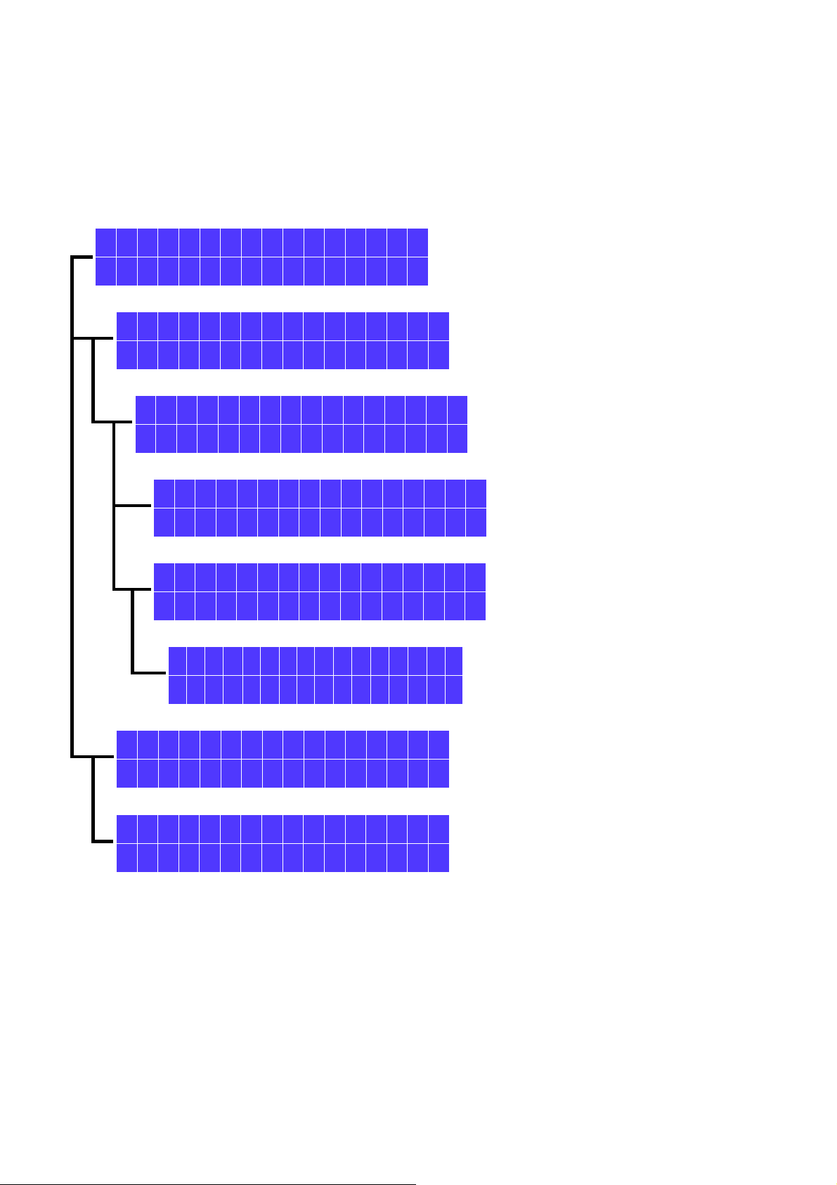
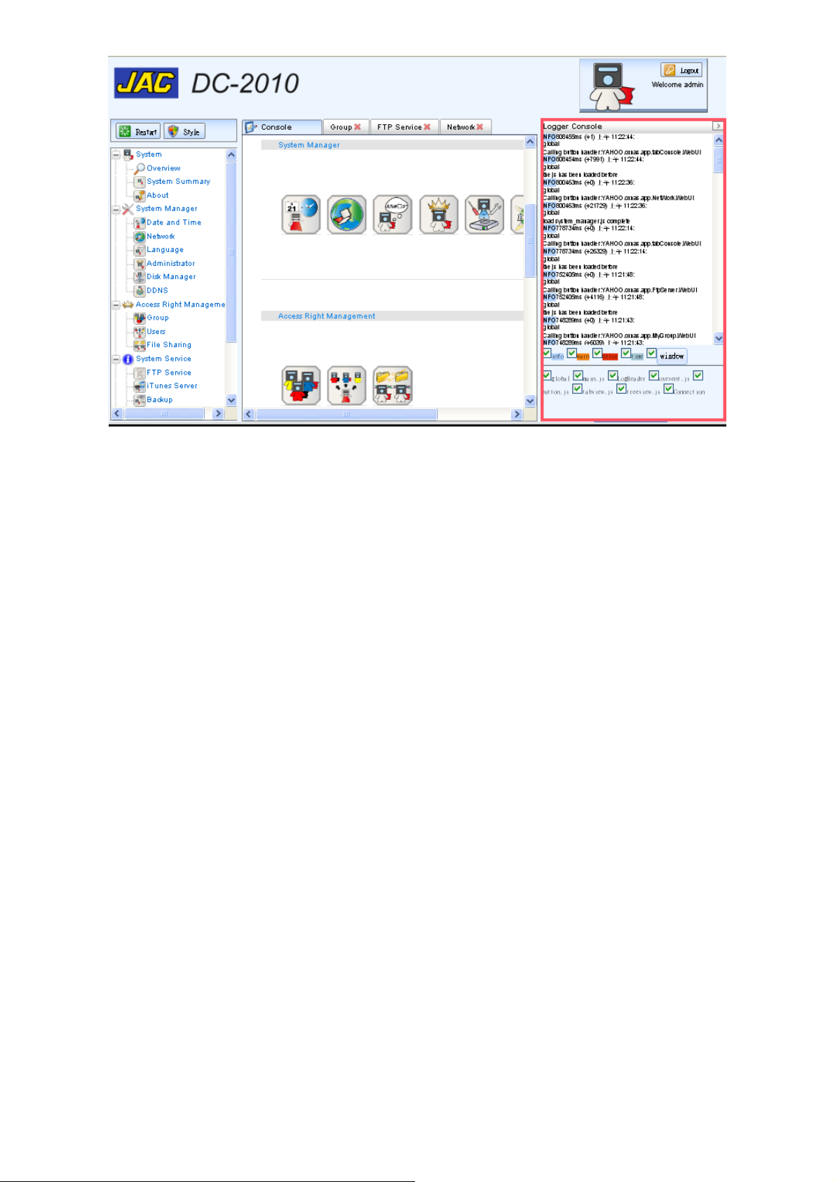
5 Introduction to web storage manager
The above picture is the layout of the web storage manager.
A zone: the web storage manager provided function list.
B zone: Restart—remote DC2010 restart, it needs user name and password to enable the restart.
Style— the web page display style
C zone: the web tab area for fast page changing, if the tabs is more than 6, an alarm will request you
close for further display. Please click the close icon on the tab to close the undesired display.
D zone: logout icon, if you just close the browser without logout, the DC2010 will wait about 5
minutes to re-log in.
E zone: the log message area, you can click the ‘K’ to display logging message. There are many display
options for you to select to display the message you want.
The icons at the middle are the specific function icons of the web storage manager, you can click any
icon to enter the function it provides.
27
28

6 System information from web storage manager
Note: Please use IE8(or later), Firefox 3.0 (or later), Google Chrome as web browser and use
1024 x 768 (or higher resolution) as display resolution
The web storage manager is a web based management interface. It provides 5 sub functions: system
information, system manager, access right management, system service and application.
6.1 Login the administration page
Open the web browser and key in the IP address of DC2010. If you do not know the IP address the
current DC2010 occupied, please take a look at the panel of DC2010. (If you access the DC2010
administration page from external, please confirm that the DC2010 has mapped to external IP by router
or gateway and use the mapped IP to connect).
For example, 192.168.0.40 is the current IP occupied by DC2010 then key in the 192.168.0.40 as
the address to be visited of the browser.
If the browser give a warning of security certificate problem, please choose proceed anyway.
29
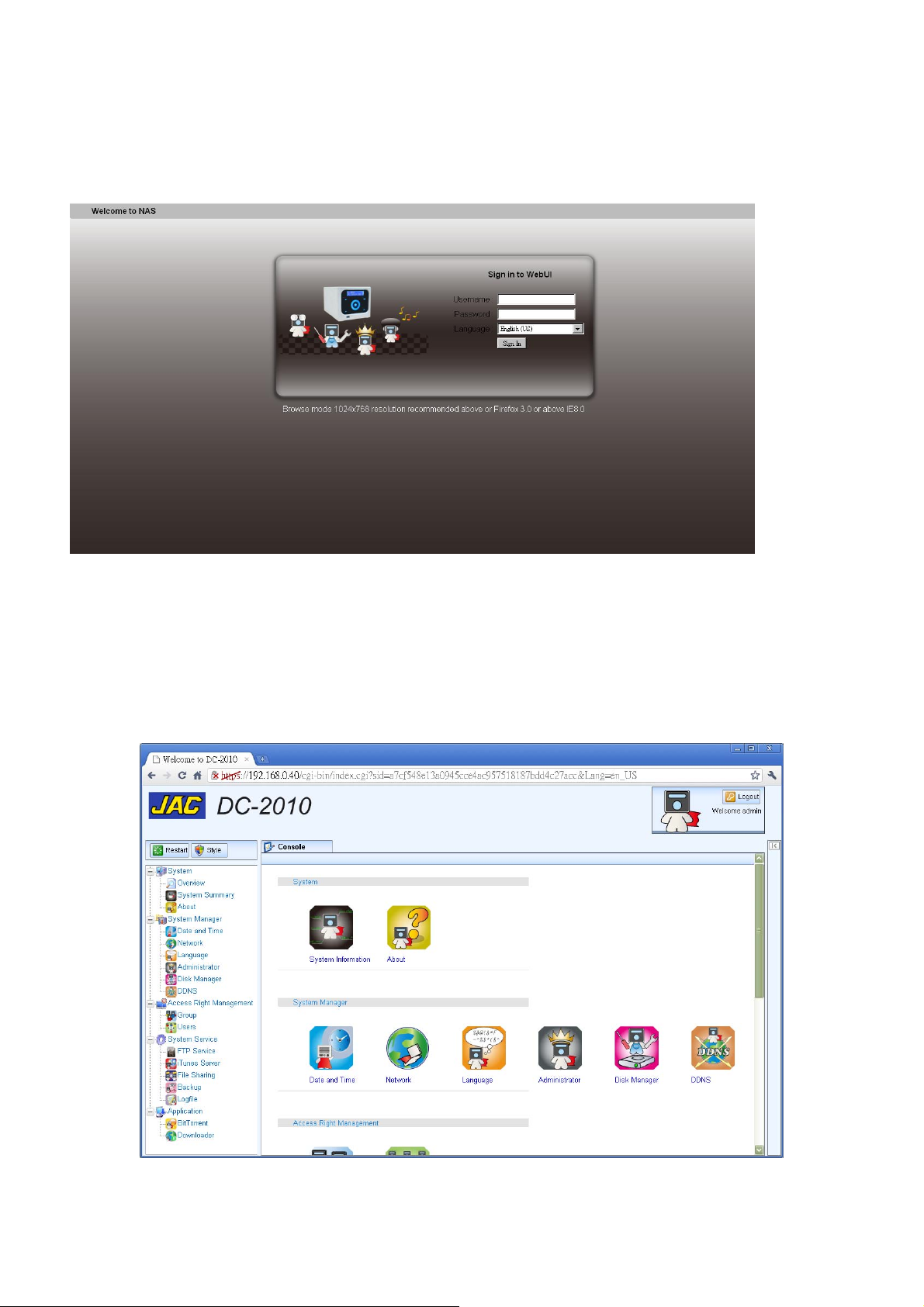
If you have not change the administrator’s name and password, you should use the default
username: admin and default password: 123456 to log in.
On the same web page, you can choose the language to be displayed (currently only English,
Chinese and Japanese can be choose).
6.2 System -> Overview
There are 5 major function groups on the left hand side of the web page:
System, System Manager, Access Right Management, System Service, Application.
30

6.3 System -> Summary
Device Name: display the device name set at System Manager->Network.
Workgroup Name: display workgroup name set at System Manager->Network.
IP Address: the IP address set
(set at System Manager->Network or by DC2010 touch panel)
Firmware Version: version on current system (defined by manufacture)
Hard Disk Capacity: capacity of the hard disk installed
Hard Disk Usage: used capacity
31

7 System management from the web storage manager
7.1 System Manager -> Date and Time To setup and adjust the server time.
Time Zone: select the time zone where your server is located
32
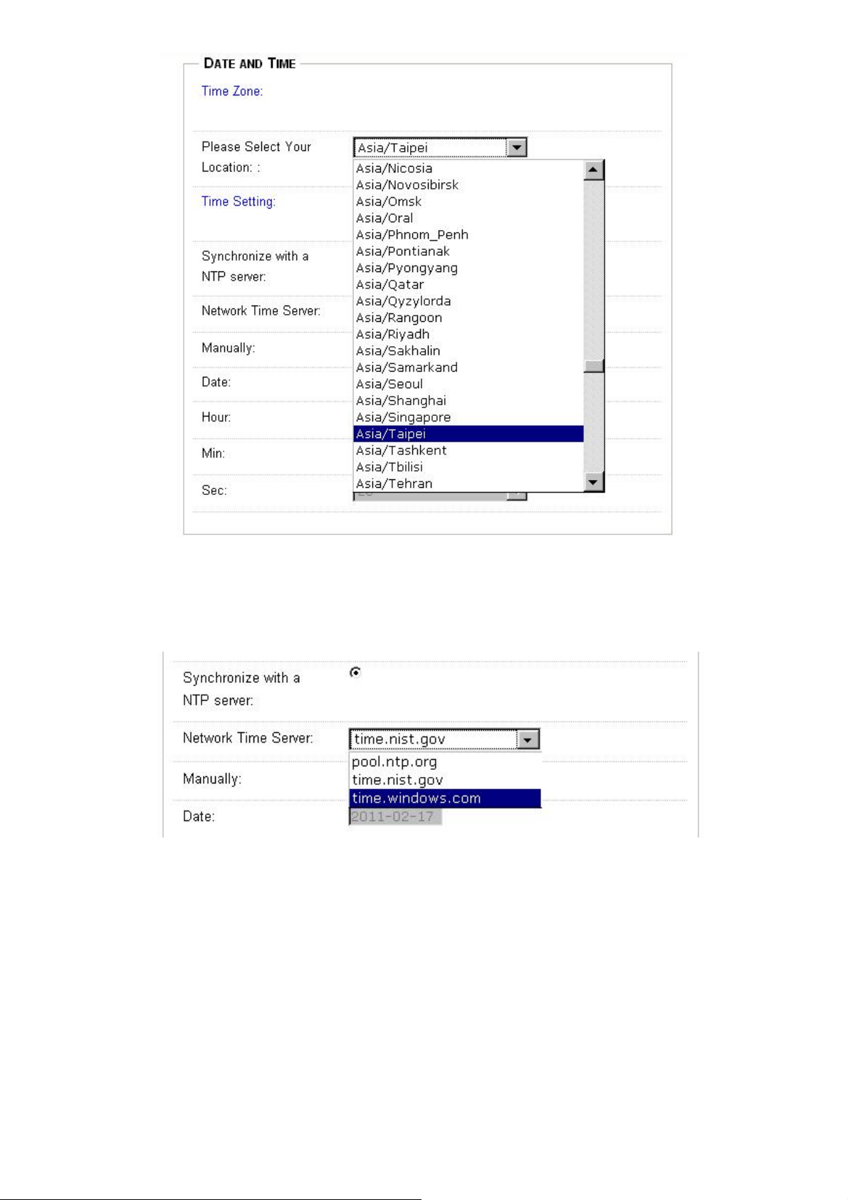
Time Setting: To choose the server time will synchronize with external standard time server (NTP
server) or internal clock.
Synchronize with a NTP server:choose the server you prefer.
33

Manually: setup the internal real time clock and the server synchronizes with it.
You should click the date icon to choose the date you will set.
Either Synchronize with a NTP server or Manually mode, you must click the Apply button to save
the settings to the server.
34

7.2 System Manager -> Network
To set up the network related parameters.
Device Name:set the device name, the default name is DC2010.
If you have multiple devices, it is better to give different names.
LAN Setting: setup the IP manually or Automatically define by DHCP.
If you choose DHCP, the IP related field will be hidden and no need to setup manually.
35

If you choose Manual, you must fill the IP you assign to this server.
Each field of the IP address is in the 0~255 range.
For example, you assign IP at 192.168.0.40:
Subnet Mask: Mask of the IP address.
Jumbo Frame: the frame data size for jumbo frame (bigger frame size will increase file transfer
rate but if bad quality of network, it also consumes more time to resend).
Default Gateway: setup the gateway IP.
DNS Server: setup the IP of name server.
After all parameters are setup, use Apply button to save the data.
Special Notes:
The server IP, Netmask, Gateway and DNS are very important parameters to the DC2010. Any
error setting will cause mal-function. Please consult with your network administrator or the
network experts. You can also get the knowledge form wiki website.
36

7.3 System Manager -> Language
You can choose the language you preferred used in the web storage management interface.
Currently, we provide 3 languages: English, Japanese and Traditional Chinese. Choose then click apply
to activate or cancel to keep the old setting.
37
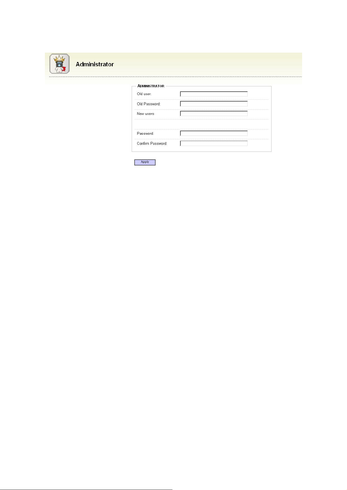
7.4 System Manager -> Administrator
Old user:the previous administrator’s name
Old Password:the previous name
New users:new administrator’s name you want to use
Password Strength:pass word security strength
Password:your new password
Confirm Password:password confirmation
Click ‘Apply’ to store and change setting.
38

7.5 System Manager -> Disk Manager
There are two possible disks: internal disk and external disk. The internal disk is the disk installed in
the DC2010 and external disk is the disk sees from the USB port.
Internal Disk Manager
Choose ‘Internal Disk Manager’, you will get the information of the internal RAID disks.
External Disk Manager
Choose ‘External Disk Manager’, you will get the information attached at the USB port.
39
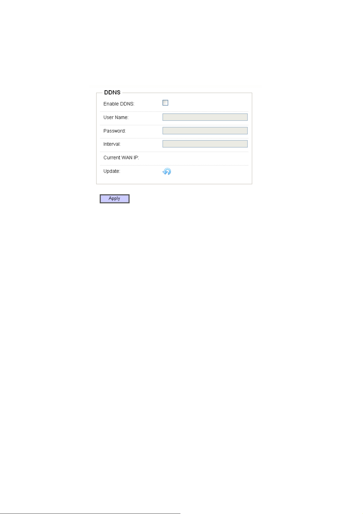
7.6 System Manager -> DDNS
The DDNS(dynamic direct name server, dynamic DNS) is used for the dynamic IP, which is not
fixed at each time you hook on the internet, the DDNS will give the user as if the IP is fixed. You must
register you web name on some DDNS server, each time the guests visit your web site the server will
route to the IP now you are using.
Enable DDNS:Enable or disable DDNS function, if your IP is dynamic, please check this function.
Username:the username you registered on the DDNS server.
Password:password you registered on the DDNS server.
Interval:the interval to update the DDNS.
Current WAN IP:current dynamic IP you got to communicate with the DDNS.
Click ‘Apply’ to store and change setting.
40

8 Access Right Management from the web storage manager
8.1 Access Right Management -> Group management
Group management is used to setup the authority of groups, which will simplify the user
management. Users can be belonged to one or several groups to define their authentication.
Add group:add new group. (Icon under the Group label.)
Delete group:delete the existing group. If no group available, the delete group will not display.
41
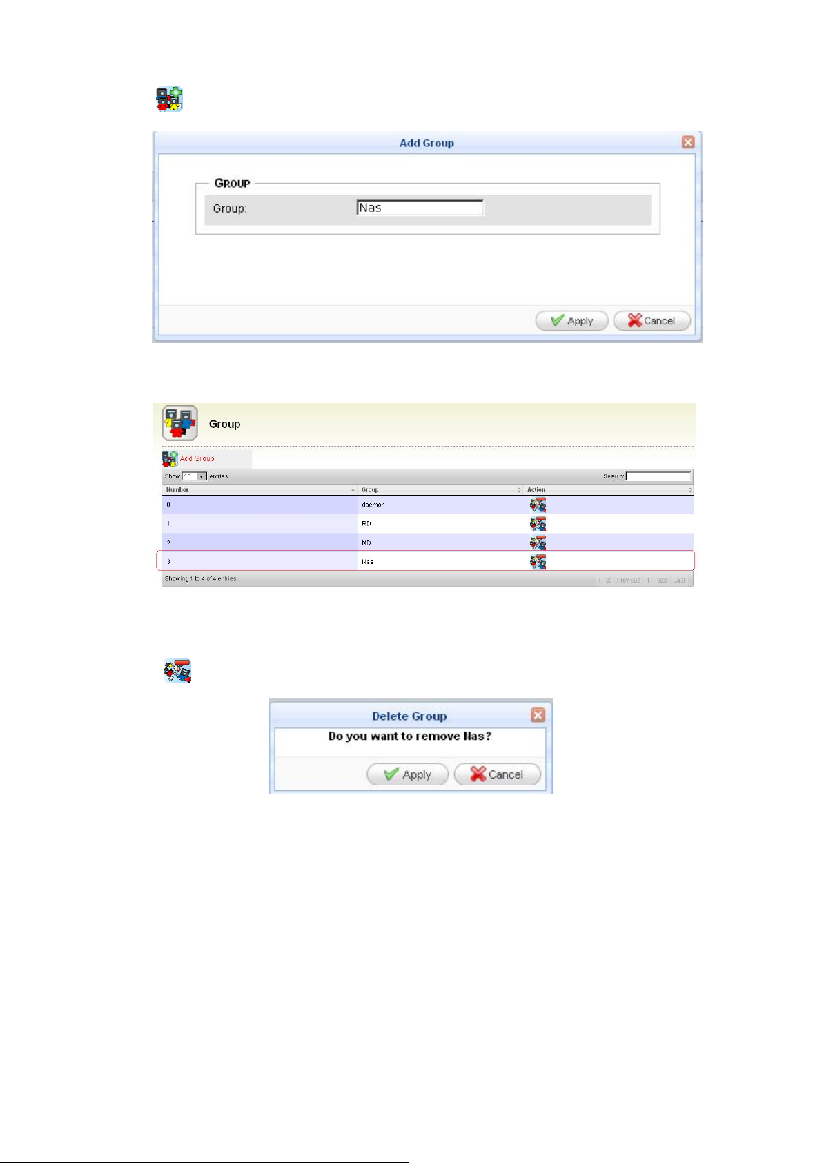
How to add a group:
1. Click Add group icon.
2. Key in the group name.
3. Click ‘Apply’ to enter the data.
How to delete a group:
1. Click Delete group at the group you want to delete.
2. For example to delete NAS group. Click the delete icon of the NAS group then the pop up
screen wants you to confirm. Click ‘Apply’ to confirm or ‘Cancel’ to skip.
42

8.2 Access Right Management -> User management
There are 3 functions in user management:
Add user: add new user.
Modify user: modify user’s setting
Delete user: delete user
43

How to add a user:
1. Click Add user to enter add user mode.
2. Select one of the name lists in the main group. For example ‘Nas’. (The list is setup at Group
management)
44

3. Select subgroup by click on the items in the list. (Multiple select can use the mouse click with
control key pressed). For example choose RD,MD as subgroup, you must press the control key
then click on RD and MD. The selected items will be highlighted.
4. Fill the user name and password.
5. Click ‘Apply’ to add a new user or click ‘Cancel’ to discard the setting.
6. If the new user is successfully added, you will have it in the user list.
45

Modify a user attribute
1. Click Modify user to enter modify user attribute mode.
2. The main group, subgroup and password are the attributes to be modified.
3. Click ‘Apply’ to confirm the modification or click ‘Cancel’ to discard modification.
How to delete a user:
1. Click Delete user to delete the user. for example we want to delete a user named ‘test’, we
must find out the column the user is listed then click the rightmost delete user icon.
2. Select ‘Delete’ to confirm or select ‘Cancel’ to discard.
46
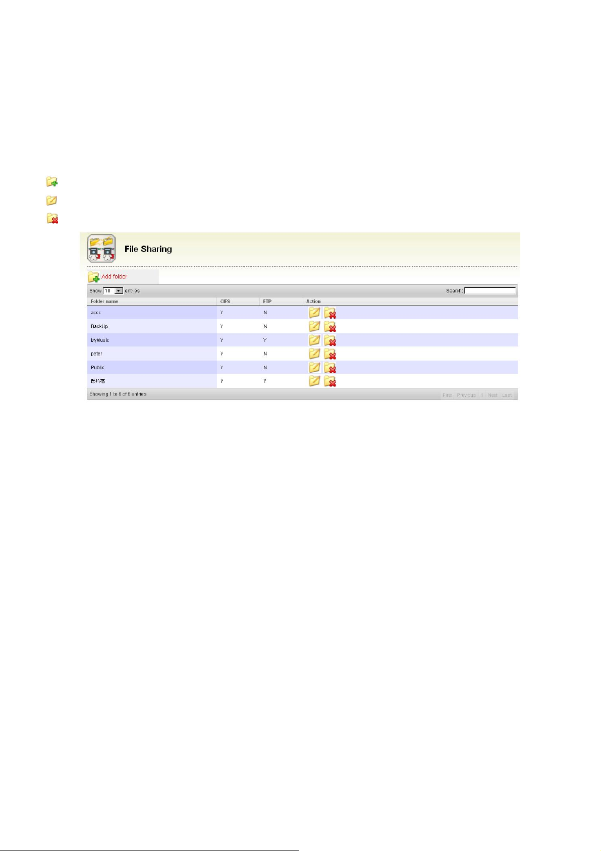
8.3 Access Right Management -> File Sharing There are 2 file types of files sharing: CIFS(Common Internet File System, used for windows
neighboring) and FTP (File Transfer Protocol, a standard network protocol used to copy a file from one
host to another over a TCP-based network). You can enable or disable the file protocol for the designate
file directory, which will decide the function you will provide.
There are 3 functions in file sharing:
Add folder: add a new folder
Modify folder: modify the folder attribute
Delete folder: delete a folder
47

How to add a folder:
1. Click Add folder to enter add folder mode.
2. In ‘Share’ column key in the folder name you want. say ‘TEST’ for example.
3. In ‘Services’ column, choose the file protocol you want to use.
4. In ‘User Name’ column, the user authentication is Full (read/write enabled), Read Only or None
(disable read/write). Choose the one you want.
5. In ‘Group’ column, the group authentication can be Full (read/write enabled), Read Only or None
(disable read/write). Choose the one you want.
Note:
If group and user authentication is conflict, the policy is enable function has higher priority.
48

6. Click ‘Apply’ to enter the data or click ‘Cancel’ to discard setting.
7. If you click “apply’ to enter data, you will be able to watch the new added folder in the file sharing
list.
49

How to modify folder:
1. Click Modify folder to modify attributes.
2. You can modify the authentication, as you need.
3. Click ‘Apply’ to confirm the modification or click ‘Cancel’ to discard modification.
How to delete folder:
1. Click Delete folder in the folder list to delete the folder.
For example, click the delete icon in the NAS column; the message will pop up as follows.
2. Click ‘Apply’ to confirm the deletion or click ‘Cancel’ to discard deletion.
50
9 System service
9.1 System Service -> FTP Service
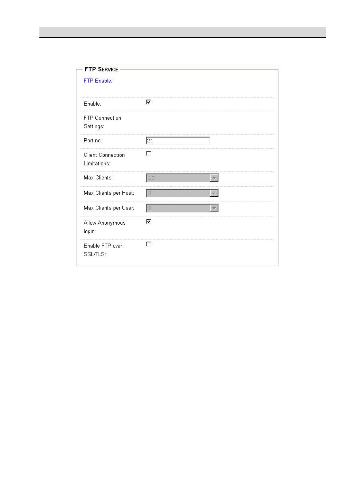
1. FTP service web page is used for FTP configuration.
FTP Enable: check it will enable the FTP service else no FTP service.
FTP Connection Setting
Port no.: FTP service port, the default is 21
Client Connection Limitations: Check to configure the following settings else no limit.
Max Clients: Maximum clients allowable.
Max Clients per Host: maximum connections per IP.
Max Clients per User: maximum connections per user.
Allow Anonymous login: check to enable anonymous log in.
Enable FTP over SSL/TLS: check to enable SSL/TLS security connection.
2. Click ‘Apply’ to confirm the configuration or click ‘Cancel’ to discard configuration.
51

9.2 System Service -> iTunes Service
1. iTunes service web page is used for iTunes server configuration.
iTunes Enable: Check to enable iTunes service else no service of iTunes.
If you configure to enable the iTunes service, the DC2010 will share the mp3 files under
\Public\Music\ (defined in ‘Share Folder’ option) in iTunes format. Any computer within the same
domain, which installed iTunes software will able to find, to browse, to play the files in DC2010.
iTunes Server Settings
Share Folder: define which folder will be shared
Music Tags Codepage: define the music tag language code page.
Rescan Interval: define how long the folder will be scanned to open files to public.
2. Click ‘Apply’ to confirm the configuration or click ‘Cancel’ to discard configuration.
How to use iTunes
1. Your computer must install iTunes software
2. Open the iTunes application program; it will automatically scan the iTunes server.
3. You will find the server on your DC2010 device name. (Say, your DC2010 is named as jsnas then the
iTunes will display ‘jsnas’ as the iTunes server name)
52

53
53
9.3 System Service -> Backup There are two types of backup available, remote backup and local USB backup.
Remote backup
For safety reason we want to backup data automatically to a different place. Using remote backup
you need 2 working DC2010’s on internet. Local DC2010 and remote DC2010. Then you can configure
to backup data from local to remote automatically.
Let us make a clear definition of remote server and local server, we define:
remote server: a server that will store the backup data from another server.
local server: a server that will send the stored data to other server for backup purpose.
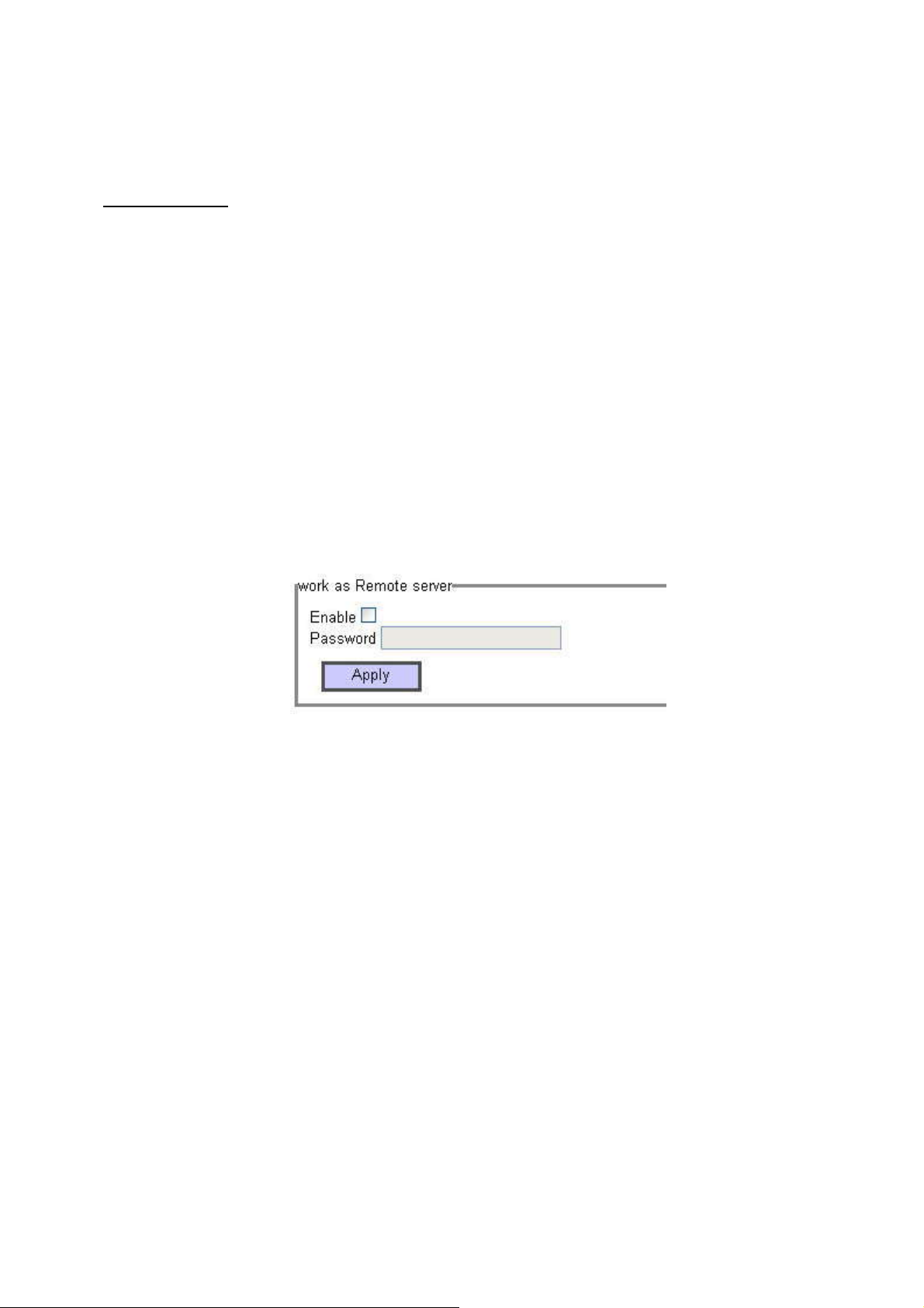
1. Remote server setup
First of all, you must log in the remote server and enable it to work as remote server and give it a
special password (may be different from the administrator password) then click apply to enable the
server.
But on the local server, if you do not want it to work as remote server, please do not enable the
function to work as remote server.
54

2. Local server setup
Available folders: the folders in the local server.
Backup folders: the folders (in the local server) to be backup.
Destination folder: the directory (in the remote server) which you want to backup to.
Destination IP: the IP of remote DC2010.
Destination Password: The password of remote DC2010 for remote backup purpose.
Backup: There are 4 backup modes.
Do not back up: setup configuration only and do not start backup function.
immediately backup: backup immediately after click ‘Apply’.
55

once backup: one time backup on schedule time.
The schedule date and time options will be displayed. Setup the data, as you need.
periodic backup: backup on periodic scheduled time.
Click ‘Apply’ to confirm the configuration.
How to recover files from remote backup
The remote backup keeps your data in a safety place, if you need to restore to the original local
DC2010, you must follow the instructions:
1. On the remote DC2010, please enter the web storage management page.
2. In the Access right management -> File Sharing, modify the attributes cifs and FTP of folder
BackUp to enable state.
56
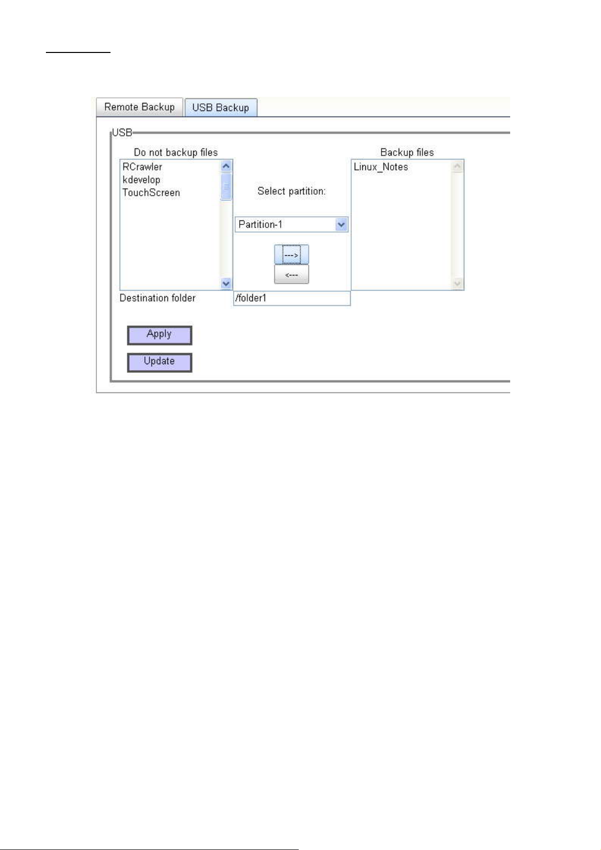
USB backup
USB backup is used for backing up data from USB to DC2010.
Do not backup files: file list of do not back up files.
Backup files: the files you want to backup.
Select partition: select the partition of the hooked USB.
Destination folder: the destination path of DC2010 that you want to put the file from USB.
(you must key in)
How to USB backup
1. If you have hookup a USB disk and you select the USB backup. The screen will be as above (the files
on the USB will display on the Do not backup files list)
2. Click on the file and using -> or <- to configure the file selection.
3. Assign the destination path of the DC2010 that you want to backup the files from USB.
4. Click ‘Apply’ to start the operation.
57
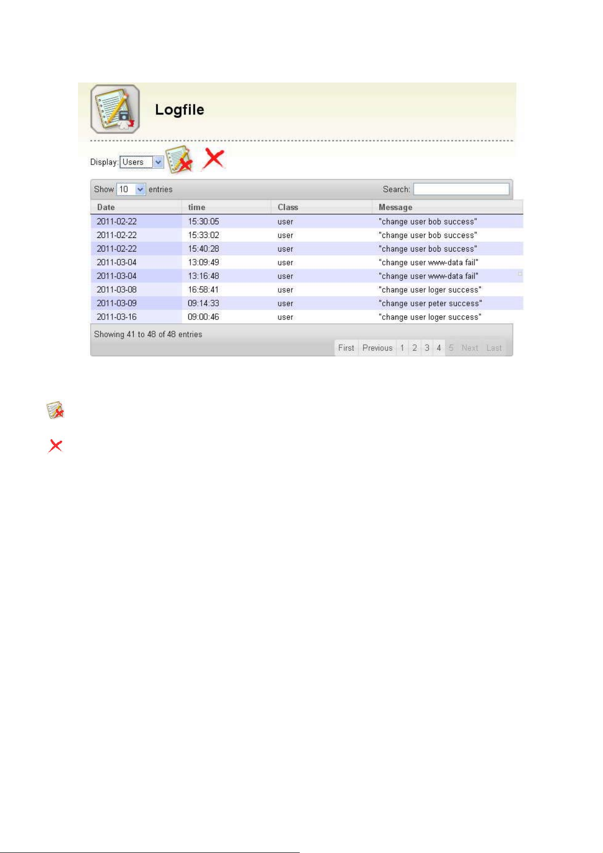
9.4 System Service -> Log file
Log file will record the date, time, login user and login IP’s and the DC2010 echo messages. It
provides information for you to debug or monitoring the operations.
Delete the log file: delete the log file, all the logging information will be cleared.
Delete log messages: delete the selected log message.
display: select the display item attribute, there are: ALL, System, Users, Group, Backup, FTP to
choose.
Show entries: select the list number per page.
58

How to delete the log file
1. Click Delete the log file, if you want to clear all the log messages.
2. Click ‘Apply’ to confirm the operation or click ‘Cancel’ to discard the operation.
How to delete a log message
1. Highlight the log message you want to delete.
2. Click
Delete log messages to delete it.
59

10 Application
Torrent files are part of a P2P (peer to peer) trading system that make transferring files from one
person to another on the Internet very easy, quick and effective.
It is important to note that torrent sharing is different from other types of P2P services, you need
a .torrent files that contain the information required for a torrent client to find, manage and download the
requested file.
10.1 BitTorrent
First of all need to prepare BitTorrent file, you can relate forums on the Internet, websites to
find the torrent to download.
BitTorrent services: to open BT BT-related functions and settings to set.
If BT function has not enabled, the first start prompt window will appear。
Click OK then the web will display the starting BitTorrent service screen.
60
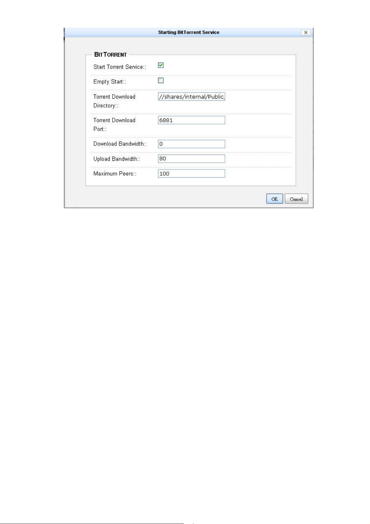
Start Torrent Service:Open BT service.
Empty Start:Stop BT service
Torrent Download Directory: directory to store TTorrent downloaded files
Download Port:Torrent download port.
Download Bandwidth:Download bandwidth (kbps) (0 means no limit)
Upload Bandwidth:Upload bandwidth (kbps) (0 means no limit)
Maximum Peers:Maximum shared users
Setup all the required information and check “Start Torrent Service” then click “OK” to start BT service.
(the following screen has already some BT .torrent stored)
61

Add a new torrent download: File extension must be .toreent
Use browse to select a torrent which is already download from other website. The name of the file
to be download will display in the name column.
62
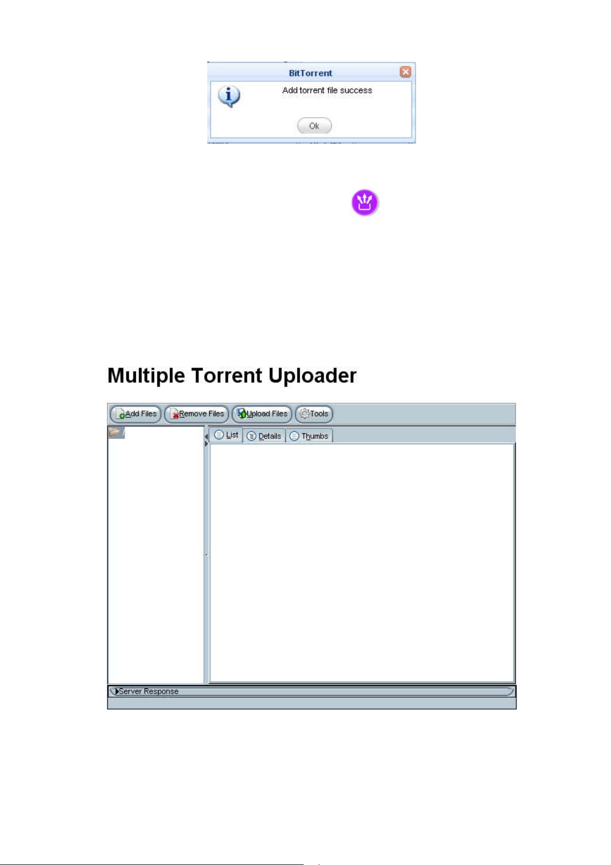
Click Apply and if add function is successful, then
Multiple Upload:
When you want to add more than a torrent, you can use the multiple upload to add multiple
tasks. (If your computer do not have JAVA package installed, the system will ask you to download and
add the package).
After finish the progress of JAVA, etc., there will be a file management interface Multiple Torrent
uploader.
Add Files to add multiple files
Remove Files to delete the unwanted files.
Upload Filesa to load the .torrent to the DC2010 BT server.
63

BT service
Now you can choose the .torrent you want to start download, say the Fedora file as the above
shown. Click to start BT service. If you want to stop, select the .torrent you want to stop then
click to stop it.
If you want to delete a .torrent, highlight to select it then click to delete.
If you want to shutdown the BT service, click to stop the service.
You can also click to view the logging file about the BT service.
64
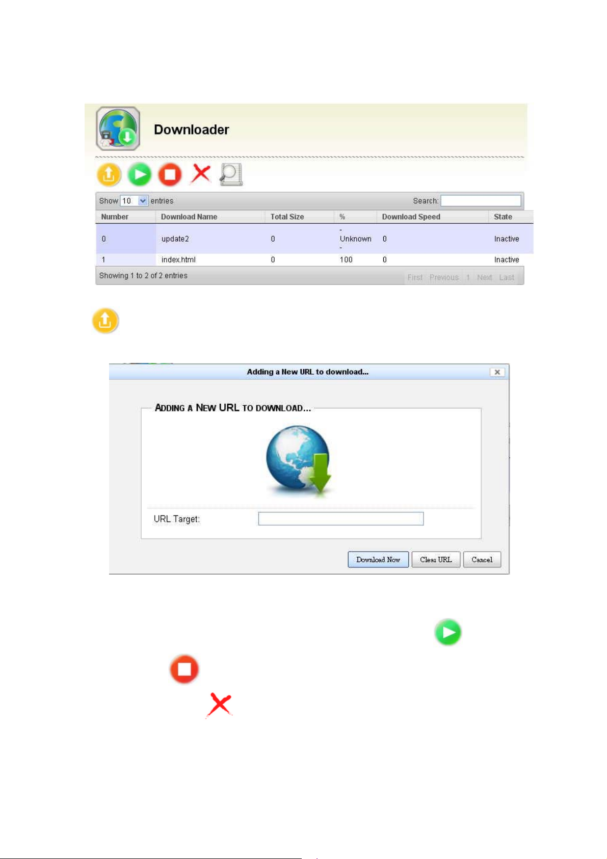
10.2 Downloader
The downloader service is used for the file download automatically from some service provider and
save the file under the directory” Public”.
Click to add a new download URL. The add new URL screen will show as follows.
Key in the URL with the file path and click Download Now to start download.
Press the "Clear URL" will clear the keyed in URL, press "Cancel" will exit to the main menu.
You can also control the download by highlighting the URL and clicking to resume the
download or clicking to pause the download. If you want to delete a preset download URL,
click to highlight it then click to delete. But please watch the state it is inactive that you can
delete.
65

The confirmation prompt ask you to confirm the deletion.
66

11 System update
Online software updates, this file will be downloaded on the official website, then software updates from
the webUI
System update:Can download the update file from the update DC-2010 system or web page。
Click Choose File to select a file there will be a picture, the file extension tar, after being
confirmed press Open.
67
 Loading...