

Page 1

2 Channel, 2 Model Memory
AM Computer Racing System
JR XR-2 7/15/99 8:35 AM Page 1
Page 2
2
Lithium Battery 9
Memory Backup Screen 9
Accessing the System Mode 10
Model Name Entry 10
Data Reset 11
Accessing the Function Mode 12
Model Select 13
Travel Adjust 14
Steering Rate 15
Sub-Trim 16
Servo Reversing 17
Accessing the Direct 18
Trim Mode
Steering Trim 19
Throttle Trim 19
Steering Dual Rate Trim 20
Adjustment (Grip Lever B)
Brake Endpoint Adjustment 21
BRG (Grip Lever A
Throttle Travel Adjust)
XR-2 Data Sheet 22
Frequency Chart 22
Warranty and 23
Service Information
Introduction to 2
the XR-2 Radio System
XR-2 Quick Start Setup 3
Systems Features 4
Transmitter Features 4
Receiver Features 4
Servo Features 4
System Specifications 4
System Components 4
Transmitter Specifications 4
Receiver Specifications 4
Servo Specifications 4
Control Identification 5
and Location
Steering Tension Adjustment 6
Charging Jack 6
R/C Safety Precautions 6
Receiver/Servo Connections 7
and Installation
Operating Your Model 8
Servo Layout 8
Key Input and Display 8
Display Screens 9
Normal Display Screen 9
Low Battery Screen 9
T able of Contents
Introduction to the XR-2
Radio System
Thank you for purchasing the XR-2 two-channel radio system. This system has been designed to provide the R/C racer
with a high quality, user friendly radio system that can be
depended upon year after year, race after race. It is important
that you carefully read this manual before attempting to
operate your XR-2 system. For your convenience, a blank
data sheet has been included in the back of this manual.
Once you have input all the necessary data for a particular
model into your transmitter, we strongly recommend that
you immediately write that information down on the data
sheet provided. This insures that, in the rare case of a memory failure, you will not lose your models’ set-up data.
For those who would like to get out to the track quickly with
just the basic radio set-up, please refer to the Quick Start
section that follows.
JR XR-2 7/15/99 8:35 AM Page 2
Page 3
3
XR-2 Quick Start Setup
In this manual you’ll find in-depth instructions detailing all
the steps and procedures you’ll need to follow in order to
program each of the XR-2’s features correctly. For those racers who want to get to the track fast, we have provided the
Quick Start section below. Quick Start covers the basic programming information necessary to get you to the track fast.
Later, when you want to learn more about the specific
features of the XR-2, refer to the appropriate page(s) in this
manual for more detailed programming information.
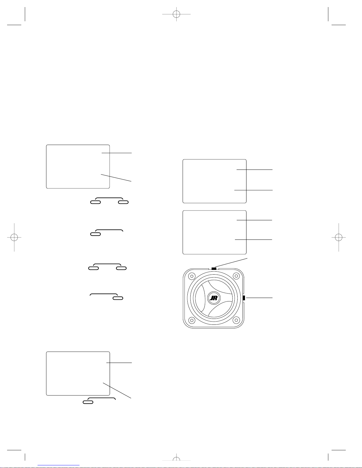
Servo Reversing
1. With the transmitter power switch on, press the MODE
key to enter the Function Mode.
2. Press the MODE key four times until ST appears on the
screen. The ST indicates the steering servo reversing
screen.
3. Press the increase or decrease key to move the cursor to
the desired servo direction (Rev.Norm).
4. Press the CHANNEL key once to access the throttle servo
reversing screen.
5. To select the direction of the throttle servo, repeat Step 3
above.
Travel Adjustment
1. From the Servo Reverse function, press the MODE key
twice to access the Travel Adjustment function (the STR
or STL screen will appear).
Steering Adjustment:
2. Rotate the steering wheel in the desired direction (left or
right) to be adjusted.
3. Press the INCREASE or DECREASE keys to select the
desired travel value.
Throttle Adjustment:
4. Press the CHANNEL key once. FWD will appear on the
screen.
5. Press the INCREASE or DECREASE keys to select the
desired travel value.
6. Press the MODE and CHANNEL keys at the same time to
exit the Function Mode.
Servo T rim Adjustment
Steering Servo T rim Adjustment:
1. With the transmitter power switch on, move the digital
steering trim lever in the desired position to be adjusted.
The steering trim value screen will appear automatically.
Throttle Servo T rim Adjustment:
2. With the transmitter power switch on, move the digital
throttle trim lever in the desired position to be adjusted.
The throttle trim value screen will appear automatically.
st
—
REV•NORM
MODE
ENTER
CHANNEL
MODE
Indicates current
channel
ST = Steering
TH = Throttle
Indicates current
servo direction
INCREASE
CLEAR
+–
DECREASE
CHANNEL
str
100
TRVADJ.
MODE
Indicates current
adjustment position
STR = Steering right
STL = Steering left
FWD = Forward trigger
BRM = Reverse
(brake) trigger
Indicates current
value
st
0
tht
0
Indicates steering
trim function
Indicates throttle
trim function
Indicates current
value
Indicates current
value
Throttle trim
Steering trim
JR XR-2 7/15/99 8:35 AM Page 3
Page 4
4
System Features
Transmitter Features
• Two Channels
• AM modulation
• Easy-to-read LCD graphics display
• Two model memory
• Three-digit model name entry
• Electronic digital trim levers for throttle and steering
• Two assignable electronic grip levers
• Direct display trim function
• Servo reversing
• Sub-trim
• Steering dual rate
• Steering endpoint adjustment
(two points — left and right)
• Brake/throttle point adjustment
• Low battery alarm
• Plug-in crystals
• Charge jack receptacle (rechargeable batteries
not included, order JRPB958)
R-122 Receiver Features
• Two Channels
• AM modulation
• 27MHz/75MHz available
• Battery eliminator circuitry (BEC)
• Patented ABC&W interference technology
Z250 Servo Features
• Zero deadband amplifier for accurate neutral centering
• Low current drain
• Indirect drive feedback potentiometer for additional
vibration protection
• Surface Mount Technology (SMT)
• Durable nylon gear train for long life
System Specifications
System Components
XR-2 Transmitter Specifications
R-122 Receiver Specifications
Z250 Servo Specifications
Torque (oz/in) 40.3 oz/in
Speed . 25sec/60
Weight (oz) 1.47 oz
Size (in) (WxLxH) 0.73x1.52x1.32
Motor 3-pole ferrite type
Model Number NER-122
Type 2-channel/AM
ABC&W circuitry
Frequency 27/75 MHz
Sensitivity 5qs minimum
(microseconds)
Selectivity 8 KHz/50dB
Weight (oz) .88 oz
Size (in) (WxLxH) 1.26′′ ×1.76′′ ×.87′′
Receiver antenna 14.75′′
Power Supply 4.8-6.0V D/C
Model number XR-2
Encoder 2-channel computer system
RF output 27/75 MHz
Modulation AM modulation
Output power 195.0 Mw
Current drain 150 mA
Power source 1.2V x 8 dry cell
(1.2V ×8 NiCad
600 mAh optional)
Output pulse 1000-2000 (1500 neutral)
System name XR-2
Transmitter NET XR-2
Receiver R-122
Servos Z250x2 (1 if equipped with ESC
speed control)
Accessories B.E.C. switch harness with bat-
tery case Servo accessories (for
two servos) Instruction manual
JR XR-2 7/15/99 8:35 AM Page 4
Page 5

5
Control Identification and Location
Antenna
Steering wheel
Electronic digital
steering trim lever
Dot Matrix multidata LCD display
3 digit name input
Digital voltage
reading
Electronic digital
grip lever A
Electronic digital
grip lever B
Power switch
Charge jack
Mode button
= Enter function
= Clear function
Channel button
Increase button
Decrease button
Electronic digital
throttle trim lever
Throttle trigger
Adjustable
steering tension
Battery cover *
(8 AA batteries required)
*To remove, press down where it says “press” and push the cover in the direction of the arrow.
Remove the battery case and install eight AA batteries in the direction shown as molded into the
battery case. If transmitter voltage fails to register, check for correct battery installation and voltage.
JR XR-2 7/15/99 8:35 AM Page 5
Page 6
6
R/C Safety Precautions
For safe and reliable performance of your R/C model, please
carefully read and follow these guidelines:
1. Radio control models are not toys. They are capable of
inflicting serious injury to people and property. Use caution at all times when operating your model.
2. You are responsible for the safe operation of your R/C
model. You must properly install, test and operate your
model with a clear sense of that responsibility. Do not
take risks that might endanger yourself or others.
3. Running an R/C car in the streets is very dangerous to
both drivers and models. Avoid running your model in
areas occupied by full size automobiles. To locate areas
where you can safely operate your model, you should
contact your local hobby shop for R/C tracks or clubs in
your area.
4. When running an R/C boat, keep it away from any swimmers, full size boats, or wildlife. Also, watch carefully for
fishing lines that can entangle the propeller.
5. Before operating your model, make sure your frequency is
clear. If someone else is operating on the same frequency,
both models will go out of control, possibly causing damage to the models as well as others.
6. If at any time while operating your R/C model you sense
abnormal model functioning, end your operation immediately. Do not operate your model again until you are certain the problem has been corrected.
CAUTION: Control of your model is impossible without sufficient voltage for the transmitter and receiver. A weak transmitter battery will decrease your range of operation and a
weak receiver battery will slow servo movement and
decrease your range of operation. Check your receiver pack
voltage often to avoid losing control of your model. When
using a model that operates both the electric motor and the
receiver from the same battery (Battery Eliminating Circuitry
or B.E.C.), you should discontinue use when the top speed
sharply decreases or you will quickly lose control of your
model.
Steering Tension
Adjustment
Steering tension is adjustable via the recessed screw located
beneath the steering wheel (see page 5 for exact location).
Turning the screw clockwise increases the steering tension.
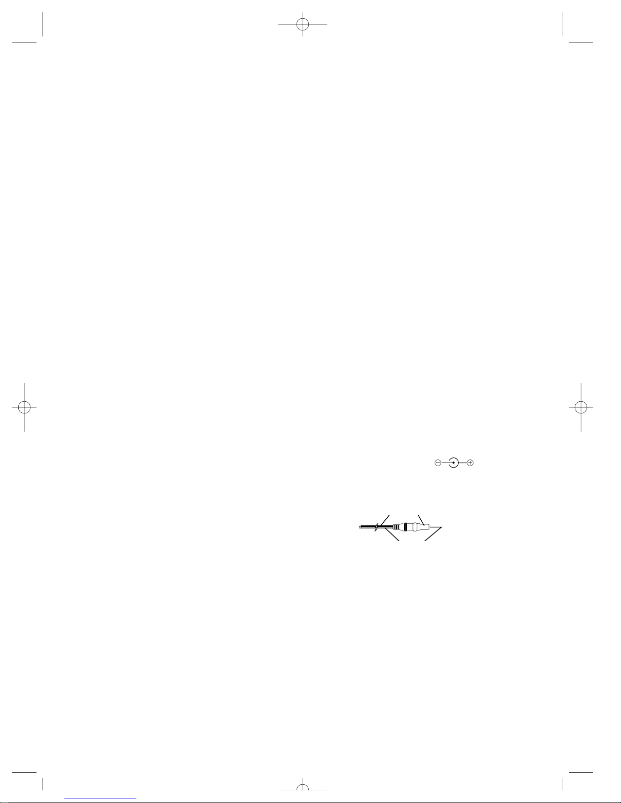
Charging Jack
Located on the right-hand side of the transmitter is the
charging jack, which accepts only JR wall chargers. Please
do not attempt to use any other brand of wall charger as it
may be reverse polarity and can cause damage to your
system. Only use the JR wall charger when the XR-2 is
equipped with Ni-Cad batteries (not included, JRPB958).
JR TRANSMITTER CHARGE JACK POLARITY:
Charger Pigtail For Transmitter
Black To Positive
Red To Negative
JR XR-2 7/15/99 8:35 AM Page 6
Page 7
7
Receiver/Servo Connections
and Installation
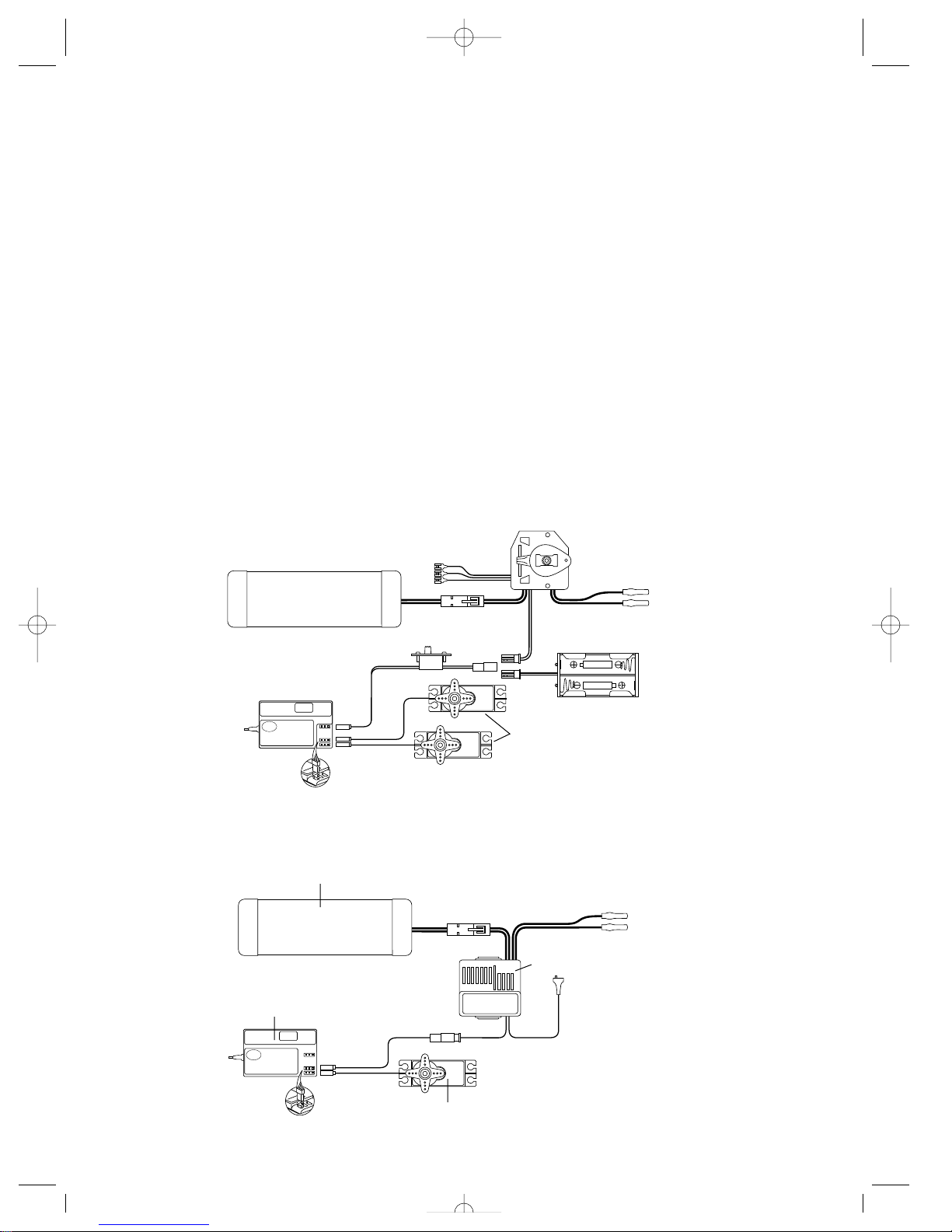
Your R-122 Receiver is equipped with Battery Eliminator
Circuitry (B.E.C.). The receiver gets its power from the
model’s Ni-Cad battery pack, thus saving the weight of an
additional receiver battery. Ni-Cad batteries from 4.8–8.4V
(4–7 cells) can be used safely. Higher voltage packs may
damage the receiver and servos.
Note: When using a separate receiver Ni-Cad as a power
source, the operating voltage range is 4.8–6.0V
(4–5 cell)
Attention: Make sure the male and female connectors have
the correct polarity (+/–) before connecting. The servo lead
and receiver case are molded so that the lead can only be
inserted correctly. Be sure to orient the servo plug correctly
for proper insertion.
You may use a separate gas to power the receiver (such as
for some electric boats or in gas-powered vehicles). A NiCad pack plugged into the BATT socket on your receiver will
operate your receiver. You may also use alkaline batteries
with the included battery box.
If you use a mechanical speed controller, please make sure
that it has the correct connector for a B.E.C. system (red connector). See Figure A below for a typical set- up.
Most electronic speed controllers are set up for B.E.C. operation and plug directly into your receiver (Function 2). See
Figure B for a typical set-up and check your speed
controller’s manual for correct installation.
BEC
BEC
Figure A – Connections to B.E.C. receiver with mechanical speed
controller. Ni-Cad battery and speed controller are not included in the
radio set.
Figure B – Connections to B.E.C. receiver with
electronic speed controller. Ni-Cad battery and
speed controller are not included in the radio set.
To Resistors
Mechanical
Speed Control
BEC Connector
Switch
R-122 Receiver
R-122
Z250 Servos
To Motor
Battery Box
(For use with optional
separate receiver battery
power)
7.2V-8.4V Battery
7.2–8.4V Battery
R122 Receiver
R122
Z250 Servo
BEC Connector
E.S.C.
To Motor
JR XR-2 7/15/99 8:35 AM Page 7
Page 8
8
Operating Y our Model
It’s important to learn the proper sequence for switching
on/off your radio system:
BEFORE OPERATION:Switch on the transmitter, then the
receiver.
AFTER OPERATION:Switch off the receiver, then the
transmitter.
This ensures that you will always have a signal to the receiver, and your R/C model will not operate out of control when
you turn off the transmitter.
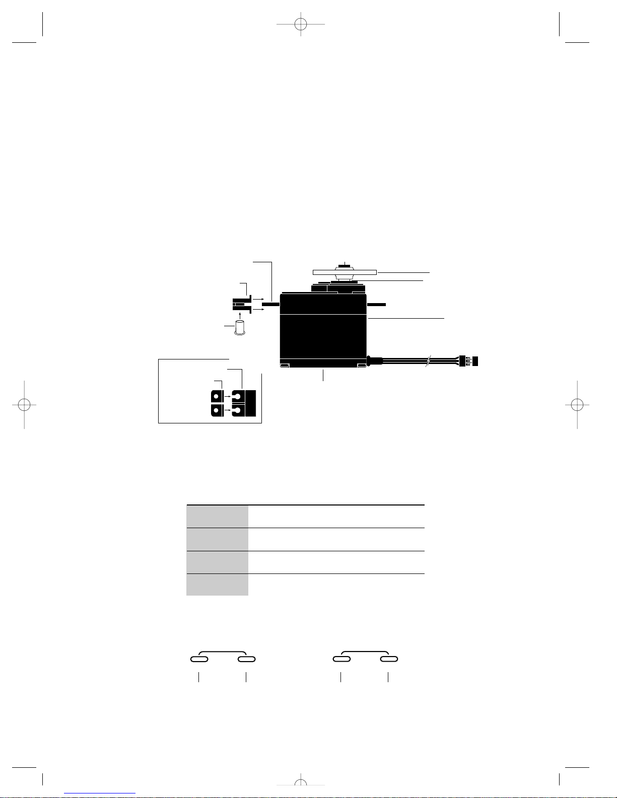
Servo Mounting Flange
Rubber Grommets
Rubber Grommets
Servo Case
Servo Lead w/Connector
Servo Output Shaft
Servo Mounting Flange
Servo Arm/Horn
Servo Arm Retaining Screw
Servo Eyelet
Z250 Servo
Top View
Key Input and Display
MODE
ENTER
CHANNEL
To enter the Function Mode press the MODE
key while the transmitter is on.
Press the INCREASE and DECREASE keys
simultaneously to clear the screen or return
to factory preset.
To enter the System Mode press the MODE
and CHANNEL keys simultaneously and
hold while turning on the transmitter.
INCREASE
CLEAR
+
–
DECREASE
Servo Layout
Note: Rubber grommets
and (sometimes)
eyelets are used in
fuel-powered
vehicles.
KEY
MODE
CHANNEL
INCREASE
DECREASE
Used to move up through the available functions
Used to select the desired channel
Used to increase the value of the selected function
Used to decrease the value of the selected function
USE
JR XR-2 7/15/99 8:35 AM Page 8
Page 9
9
Display Screens
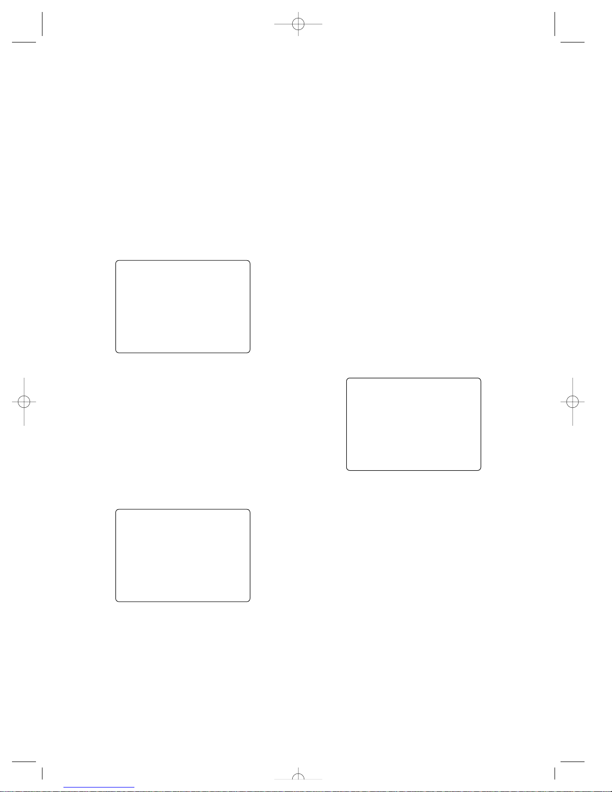
Normal Display Screen
When the power switch is turned on, the LCD screen will
read as shown here in the diagram. This screen is referred to
as the Normal Display.
Note: If any of the electronic trim buttons are moved
while in this screen, the screen will automatically
change to display the trim in use. This is called
the Direct Trim Mode. For more information on
the feature, please see page 19 of this manual.
Low Battery Screen/Lithium Battery
Backup
When the voltage of the eight AA batteries drops below 9.0
volts, the XR-2’s display screen will alternate between the
Normal (see above) and Low Battery screen (BATT) and a
continuous beeping will occur, indicating that the batteries
need to be replaced before further use. The Low Battery
screen is active during any of the three operating modes.
Lithium Battery
Your XR-2 radio system is equipped with a 5 year lithium
battery backup system. This system is designed to protect
and retain all radio programming in the event that the transmitter batteries drop below the required 9.0 volts, or the
transmitter battery case is removed during battery changes. If
after five years it becomes necessary to replace the lithium
battery, return your system to the Horizon Service Center for
repair (see address, page 23).
Memory Backup Screen
If the Memory Backup screen appears, this indicates that any
programming changes made since the last time the system
was turned on must be saved by pressing the MODE and
CHANNEL buttons at the same time. If you do not save, the
recent programming changes will be lost. If this screen
appears for a second time, it is suggested that the XR-2
transmitter be returned to the Horizon Service Center for servicing (see Warranty Information, page 23).
bat
8.9V
md !
10.2V
bak
ER
JR XR-2 7/15/99 8:35 AM Page 9
Page 10
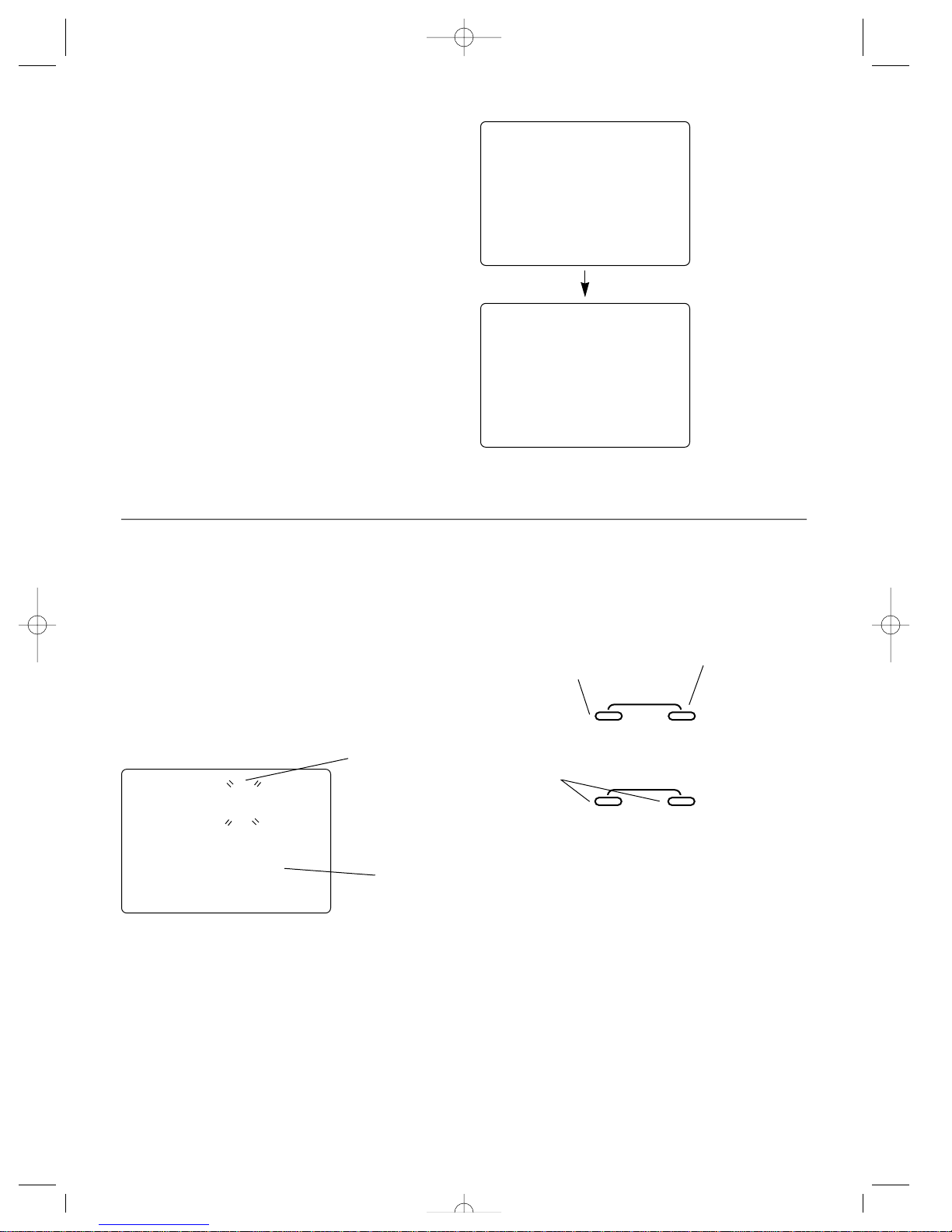
Accessing the Model Name
Entry Function
To access the Model Name Entry function, follow the steps
below:
1. Press the MODE and CHANNEL keys at the same time and
hold.
2. Turn on the transmitter power switch to enter the System
Mode.
3. MD1 should now be present on the screen.
4. Press the INCREASE or DECREASE keys to select the cor-
rect letter/number for the first character (flashing).
5. To change the remaining two characters, press the CHANNEL key until the desired character to be changed is flashing.
6. To access the Data Reset function, press the MODE key.
To exit the System Mode, either turn the transmitter power
switch off or press the MODE and CHANNEL keys at the
same time.
Model Name Entry
(System Mode)
The XR-2 allows a three-digit name to be input for each of
the two (2) models available. The current model, with name,
will then be displayed in the Normal display screen. This feature is useful to help identify different models, setups, etc.
For information on selecting models 1 or 2, please refer to
the Model Select Function (page 13).
10
Accessing the System Mode
To enter the System Mode, press both the MODE and CHANNEL keys at the same time while turning on the transmitter
power switch. By pressing the MODE key, you can now
select either the model name input or data reset functions as
shown here on the System Mode flow chart. Information for
each function is located on the page number listed next to
the function name on the flow chart.
To exit the System Mode, press the MODE and CHANNEL
keys at the same time, or simply turn off the transmitter.
md !
1
md !
1
clr
1
Model Name Entry,
page 10
Flashing character
indicates the character
to be adjusted
Current model
number
Data Reset, page 11
MODE
ENTER
CHANNEL
INCREASE
CLEAR
+–
DECREASE
Press the MODE and
CHANNEL keys at the
same time and hold to
enter the System Mode
Press the CHANNEL
key to select the
character to be
changed
Press the increase or
decrease keys to select
the correct letter/
number to be used
JR XR-2 7/15/99 8:35 AM Page 10
Page 11
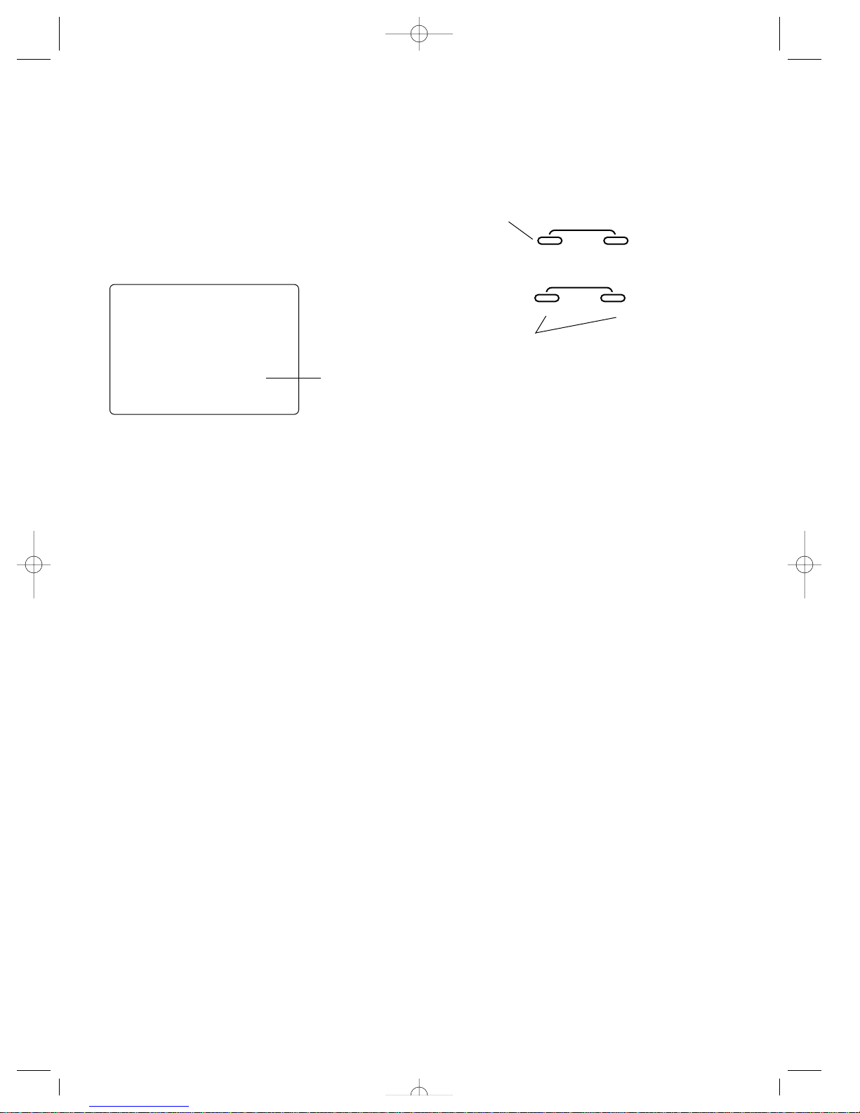
11
Data Reset (System Mode)
The Data Reset function allows you to reset all the programming in the selected model (1 or 2) to the factory default settings. Before using the Data Reset function, it’s important to
enter the Model Select function and check to make sure the
current model number indicated (1 or 2) is the model to
which you want to reset to the factory default settings. The
Model Select function is described in on page 13.
Accessing the Data Reset Function
To access the Data Reset function, follow the steps below:
1. Press the MODE and CHANNEL keys at the same time and
hold.
2. Turn on the transmitter power switch to enter the System
Mode.
3. Press the MODE key once until CLR appears on the
screen.
4. Press the INCREASE or DECREASE keys at the same time
to reset the data. To confirm that the selected model’s programming has been reset, a beep will sound and the
model number selected (1 or 2) will stop flashing.
5. To exit the System Mode, either turn the transmitter power
switch off or press the MODE and CHANNEL keys at the
same time.
MODE
ENTER
CHANNEL
INCREASE
CLEAR
+–
DECREASE
Press the MODE key to
access the Model
Name Entry function
Press the INCREASE and DECREASE keys at
the same time to reset (clear) all settings for the
selected model to the factory default settings
clr
1
Indicates model to
be reset
JR XR-2 7/15/99 8:35 AM Page 11
Page 12
12
Accessing the
Function Mode
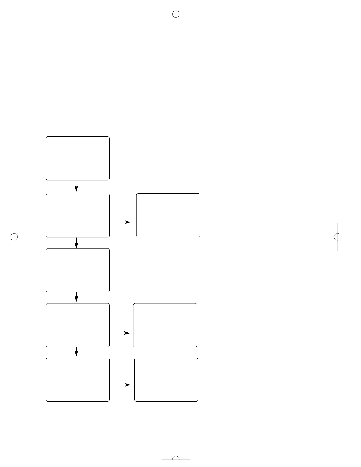
To enter the function mode, it’s necessary to first turn on the
transmitter’s power switch. Next, press the MODE key until a
beep is heard. The display will change to show the first function listed on the Function Mode flow chart as shown below.
Press the MODE key to scroll down through the functions
one by one, as shown in the flow chart. Once the desired
function has been reached, use the channel key to select the
appropriate channel (if applicable). To adjust the values of
the function, simply press the INCREASE (+) or DECREASE
(-) keys until the desired value is displayed on the screen.
md !
1
str
100
fwd
100
TRVADJ.
TRVADJ.
st
0
stm
100
∞
D/R
SB-TRM
th
0
SB-TRM
th
—
REV•NORM
st
—
REV•NORM
Mode Key Channel Key
Model Select, page 13
Travel Adjust, page 14
Steering Rate, page 15
Sub-Trim, page 16
Servo Reversing, page 17
Channel
key
Channel
key
Channel
key
JR XR-2 7/15/99 8:35 AM Page 12
Page 13
13
Model Select
(Function Mode)
The XR-2 has memory for two (2) models. This feature
allows for either two different models to be operated with the
same transmitter (a second receiver and servos must be purchased separately), or one model with two (2) different race
setups.
Accessing the Model Select Function
To access the Model Select function, follow the steps below:
1. Turn the transmitter power switch on.
2. Press the MODE key to access the Function Mode.
3. Press the MODE key until MDL appears on the screen.
4. Press the INCREASE or DECREASE keys to select the
desired model number (1 or 2).
5. Press the MODE key to access the Travel Adjust function.
6. To exit the Function Mode, either turn off the transmitter
power switch or press the MODE and CHANNEL keys at
the same time.
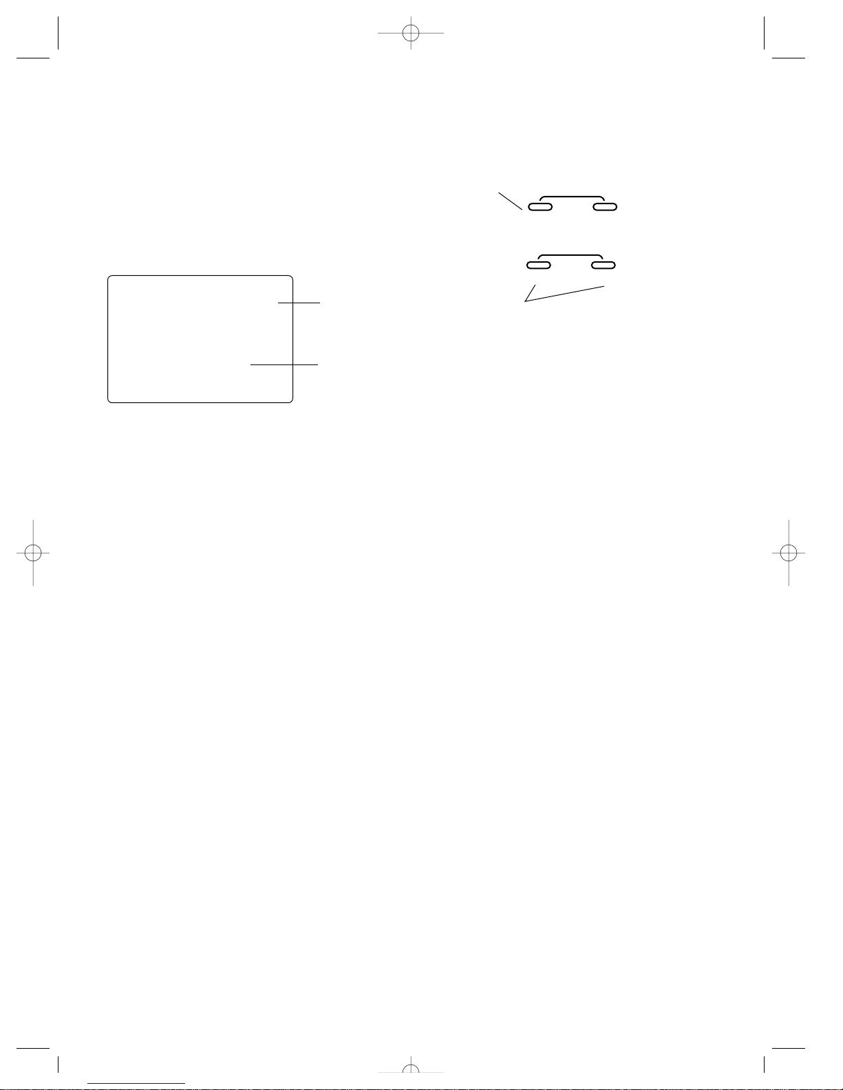
mdl
1
MODE
ENTER
CHANNEL
INCREASE
CLEAR
+–
DECREASE
Indicates Model
Select fuction
Indicates current
model number
Press the MODE key
until MDL appears on
the screen
Press the INCREASE and DECREASE keys to
select the desired model to be used (1 or 2)
JR XR-2 7/15/99 8:35 AM Page 13
Page 14
14
Travel Adjust
(Function Mode)
The Travel Adjust feature of the XR-2 allows the maximum
travel of both the steering and throttle servos to be increased
or decreased in each direction to achieve the exact servo
movement needed. The adjustment range is from 0 % to
125%. The travel adjustment is factory set to 100% for both
channels. The travel adjustment value displayed on the
screen depends on the current position of the steering wheel,
trigger, or trim lever to be adjusted. This feature is very useful either to maximize servo travel or to reduce servo overtravel to eliminate servo binding (servo moves further than
control mechanism allows), without the need for mechanical
linkage adjustment.
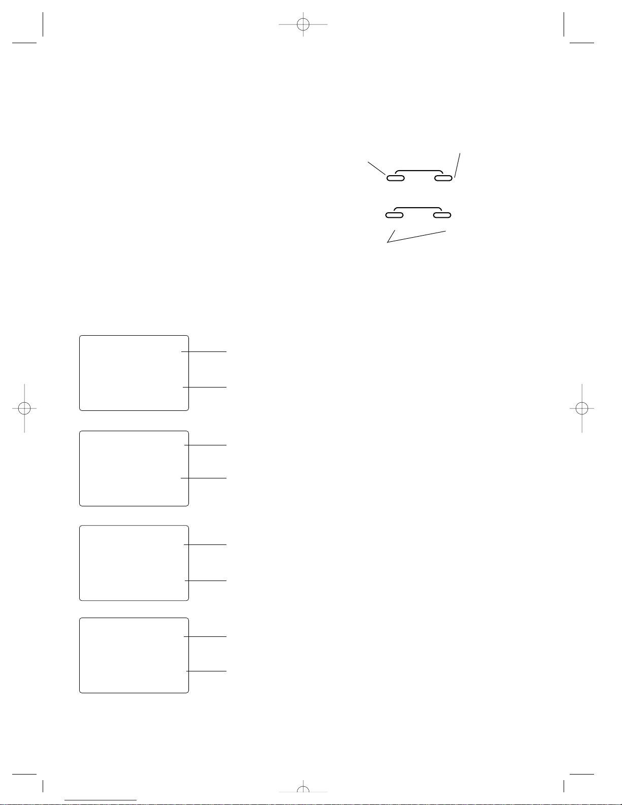
The screens below are accessed by turning the wheel to the
desired direction to be adjusted (left or right) or moving the
trigger to the forward or backward (brake) position.
Accessing The Travel Adjust
Function
To access the Travel Adjust feature, follow the step below:
1. Turn on the transmitter power switch
2 Press the MODE key to enter the Function Mode.
3. Press the MODE key until TRV ADJ appears in small let-
ters on the left side of the screen.
4. Press the CHANNEL key to select the desired channel to
be adjusted. Steering = STR (steering right) or STL (steering left); Throttle = FWD (forward) or BRM (braking or
reverse)
5. Move the steering wheel or trigger in the desired direction
for adjustment (left/right, forward/reverse or brake). Press
the INCREASE or DECREASE key to achieve the desired
amount of travel. Move the wheel/trigger in the opposite
direction to adjust the travel in the opposite direction.
6. Press the MODE key to access the Steering Dual Rate
function.
7. To exit the Function Mode, either turn off the transmitter
power switch or press the MODE and CHANNEL keys at
the same time.
Note: When setting the travel adjust values for the
steering function, it’s suggested that if possible
the maximum travel values be set to an equal
value in both directions to maintain proper steering control.
MODE
ENTER
CHANNEL
INCREASE
CLEAR
+–
DECREASE
stl
100
fwd
100
TRVADJ.
str
100
TRVADJ.
TRVADJ.
brm
100
TRVADJ.
Indicates steering left
travel adjustment
Indicates current
value
Indicates steering
right travel adjustment
Indicates forward
throttle travel
adjustment
Indicates reverse
(brake) travel
adjustment
Indicates current
value
Indicates current
value
Indicates current
value
Press the MODE key
until TRV ADJ appears
on the screen
Press the CHANNEL
key to select the
channel to be adjusted
(steering or throttle)
Move the wheel/trigger in the desired direction
and press either the INCREASE or DECREASE
keys to achieve the desired travel value
JR XR-2 7/15/99 8:35 AM Page 14
Page 15
15
Steering Rate
(Function Mode)
The Steering Rate feature of the XR-2 allows the steering
servo travel to be increased or decreased to the desired
amount required. The values of the Steering Rate function
are a percentage based from the travel adjust value set in the
Travel Adjust section.
Example: Travel adjust value 100%, Steering value 80% —
Maximum steering rate is now reduced to 80% of the maximum travel value (100%)
The Steering Rate function also works in conjunction with
the Grip Lever B Steering Rate function (page 20) and acts as
the maximum rate available through grip dial B. This feature
allows the steering rate to be increased or decreased directly
from the grip lever B while racing to maximize the steering
rate needed for the particular track conditions.
Accessing the Steering Rate
Function
To access the Steering Rate Function, follow the steps
below:
1. Turn on the transmitter power switch.
2. Press the MODE key to enter the Function Mode.
3. Press the MODE key until D/R STM appears on the
screen.
4. Press the INCREASE or DECREASE keys until the proper
steering rate is achieved.
5. Press the MODE key to access the Sub-Trim function.
6. To exit the Function Mode, either turn off the transmitter
power switch or press the MODE and CHANNEL keys at
the same time.
MODE
ENTER
CHANNEL
INCREASE
CLEAR
+–
DECREASE
stm
100
∞
D/R
Indicates Steering
Rate function
Indicates current
value
Press the INCREASE or DECREASE keys to
achieve the desired steering rate value
JR XR-2 7/15/99 8:35 AM Page 15
Page 16
16
Sub-Trim (Function Mode)
The Sub Trim function of the XR-2 is an electronic trimming
feature that allows the neutral position of the servo on either
the steering or throttle channel to be moved, while allowing
the electronic trim lever for that channel to remain in the center position. This feature is very useful as it allows the servo
arm/wheel position to be moved to help with control linkage
installation, eliminating the need to make mechanical linkage
adjustments.
Although the Sub-Trim function is a very useful feature, it is
suggested that only small amounts of sub-trim be used so
that no unwanted, non-equal servo travel is created. It’s suggested that less than 30 points of sub-trim be used during
adjustment. If more than 30 points of sub-trim are required,
it’s suggested that a mechanical linkage adjustment be performed.
Accessing the Sub-Trim Function
To access the Sub-Trim function, follow the steps below:
1. Turn on the transmitter power switch.
2. Press the MODE key to enter the Function Mode.
3. Press the MODE key until SB-TRIM appears in small
letters to the left of the screen.
4. Press the CHANNEL key to select the channel to be
adjusted (ST= Steering, TH= Throttle).
5. Press the INCREASE or DECREASE keys until the proper
servo position is achieved.
6. Press the Mode key to access the Servo Reversing
function.
7. To exit the Function Mode, either turn off the transmitter
power switch or press the MODE and CHANNEL keys at
the same time.
MODE
ENTER
CHANNEL
INCREASE
CLEAR
+–
DECREASE
st
0
SB-TRM
Indicates current
channel
ST = Steering
TH = Throttle
Indicates current
value
Press the CHANNEL
key to select the
desired channel to be
adjusted
ST = Steering
TH = Throttle
Press the INCREASE or DECREASE keys to
achieve the desired sub-trim value
JR XR-2 7/15/99 8:35 AM Page 16
Page 17
17
Accessing the Servo
Reversing Function
To access the Servo Reversing function, follow the steps
below:
1. Turn the transmitter power switch on.
2. Press the MODE key to access the Function Mode.
3. Press the MODE key until REV.NORM appears in small
letters to the right of the screen.
4. Press the CHANNEL key to select the channel to be
changed (ST = Steering, TH = Throttle).
5. Press the INCREASE or DECREASE keys to move the cursor to the desired direction.
6. To exit the Function Mode, either turn off the transmitter
power switch or press the MODE and CHANNEL keys at
the same time.
Servo Reversing
(Function Mode)
The Servo Reversing feature of the XR-2 is a very convenient
feature when setting up a new model. The purpose of the
servo reversing function is to change the direction of the
servo rotation in relation to the wheel/trigger movement. The
Servo Reversing function is available for both the steering
and throttle channels of the XR-2.
MODE
ENTER
CHANNEL
INCREASE
CLEAR
+–
DECREASE
Indicates current
channel
ST = Steering
TH = Throttle
Cursor indicates
current servo
direction
st
—
REV•NORM
Press the CHANNEL
key to select the
desired channel to be
adjusted
ST = Steering
TH = Throttle
Press the INCREASE or DECREASE keys to
move the cursor to the desired servo direction
JR XR-2 7/15/99 8:35 AM Page 17
Page 18
18
Accessing the Direct
Trim Mode
The Direct Mode function of the XR-2 is accessible through
the use of the electronic throttle or steering trim levers, as
well as the two electronic grip levers (A&B) located on the
upper portion of the grip handle. This function allows for
quick trim adjustment of these controls, without the need to
access these functions through the four keypad control keys.
To access the Direct Trim Mode function, turn on the transmitter power switch. Next, move the desired trim lever to be
adjusted. The appropriate screen for the selected trim lever
will be displayed. To adjust, simply move the trim lever in
the desired direction until the correct amount of trim is
achieved. Once the desired trim is achieved, the screen will
return to the Normal display screen after approximately five
seconds from the last trim input. If the MODE or CHANNEL
key are pressed any time during the five seconds, the system
will return to the previous screen in use.
stt
0
tht
0
brg
50
TRVADJ.
stg
70
∞
D/R
Steering Trim, page 19
Throttle Trim, page 19
Steering Dual Rate (Grip Lever B), page 20
Brake Travel Adjustment (Grip Lever A), page 21
JR XR-2 7/15/99 8:35 AM Page 18
Page 19
19
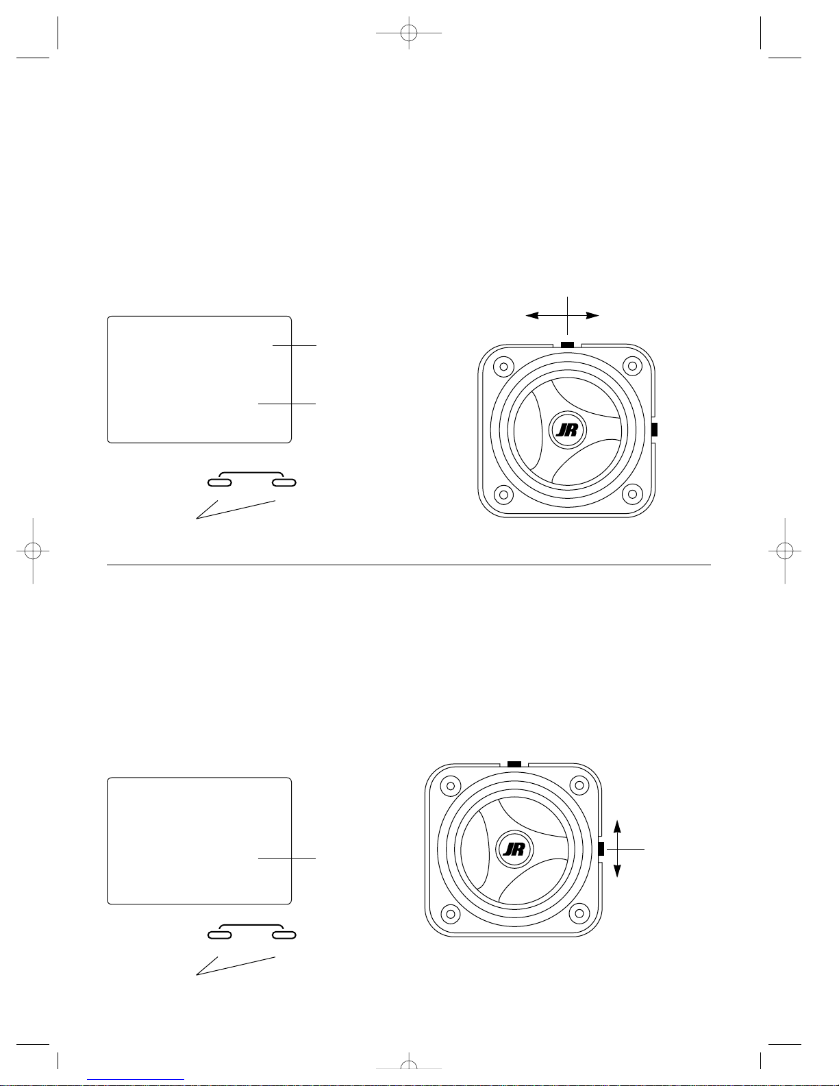
To adjust the steering trim servo position, move the
electronic steering trim lever either to the left (+) or the right
(-). As soon as the trim is moved, the STT steering trim
screen will appear, and will continue to be displayed unless
the trim lever is untouched for a period of five seconds. To
reset the trim value to 0, press the INCREASE and
DECREASE keys at the same time while the STT screen is
displayed.
Steering Trim (STT)
The XR-2 electronic steering trim lever, located just above
the steering wheel, allows the center position of the servo to
be manipulated in either direction to achieve precise centering of the steering assembly. Steering endpoint adjustment
values (page 14) remain completely independent from the
steering trim, unless the trim value exceeds the selected
endpoint values. (For example: If trim value are set at 40 and
endpoint values at 30, steering trim will override/alter the
endpoint value.)
INCREASE
CLEAR
+–
DECREASE
stt
0
Indcates steering
trim screen
Current value
Press the INCREASE and DECREASE keys at
the same time to reset the steering trim to zero
Steering Trim Location
Steering trim
Right trim (–)Left trim (+)
Press the INCREASE and DECREASE keys at the
same time to reset the throttle trim value to zero
Throttle Trim (THT)
The XR-2 electronic throttle trim lever, located to the right of
the steering wheel, allows the center position of the servo to
be manipulated in either direction to achieve precise centering of the throttle trigger neutral position. Throttle endpoint
adjustment values (page 14) remain completely independent
from the throttle trim, unless the trim value exceeds the
selected endpoint values. (For example: If the trim value is
set at 40 and the endpoint values at 30, throttle trim will
override/alter the endpoint value.)
To adjust the throttle trim servo position, move the electronic
steering trim lever either up (+) or down (-). As soon as the
trim is moved, the THT throttle trim screen will appear, and
will continue to be displayed unless the trim lever is
untouched for a period of five seconds. To reset the trim
value to zero, press the INCREASE and DECREASE keys at
the same time while the THT screen is displayed.
INCREASE
CLEAR
+–
DECREASE
Current value
Throttle Trim Location
Throttle trim
Decrease
Increase
tht
0
JR XR-2 7/15/99 8:35 AM Page 19
Page 20
20
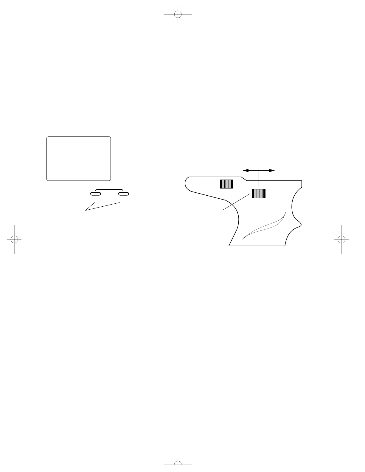
Steering Dual Rate T rim
Adjustment STG (Grip Lever B)
The steering dual rate adjustment, located at grip lever B,
allows the dual rate value (maximum servo travel) to be
increased or decreased within a range from 100% through
40% of the total dual rate value established in the Steering
Rate function (page 15). This function is very useful in race
conditions as it allows you to custom tailor the steering
radius and sensitivity for the current track conditions. Please
note that since the dual rate value shown in the STG screen
is the percentage of the value established in the Steering
Rate function, the value will not always increase or decrease,
or beep once for each time the grip lever B is moved.
To adjust the steering dual rate value, move the electronic
grip lever B either left (-) or right (+). As soon as the trim is
moved, the STG steering dual rate screen will appear, and
will continue to be displayed unless the grip lever B is
untouched for a period of five seconds. To reset the trim
value to the factory preset 70% setting, press the INCREASE
and DECREASE keys at the same time while the STG screen
is displayed.
A
B
stg
70
∞
D/R
Current value
INCREASE
CLEAR
+–
DECREASE
Decrease
Increase
Grip Lever B
Press the INCREASE and DECREASE keys at the same time
to reset the steering dual rate trim to the factory preset (70%)
JR XR-2 7/15/99 8:35 AM Page 20
Page 21
21
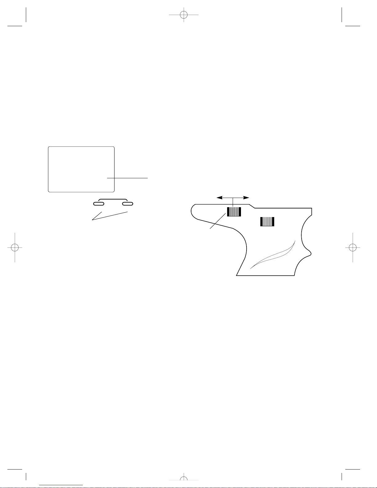
Brake Endpoint Adjustment
BRG (Grip Lever A Throttle
Travel Adjust)
The brake endpoint adjustment, located at grip lever A,
allows the maximum servo travel on the braking side of the
throttle trigger to be increased or decreased from 100% to
0% (off). This function is very useful in race conditions as it
allows the racer to custom tailor the “panic” brake value to
maximize the cars braking power for the current track conditions. Please note that since the brake endpoint value shown
in the BRG screen is a percentage of the total braking value
established in the Travel Adjust function (page 14), the value
will not always increase or decrease, or beep once for each
time the grip knob A is moved.
To adjust the brake endpoint value, move the electronic grip
lever A either left (–) or right (+). As soon as the grip lever is
moved, the BRG Travel Adjust screen will appear, and will
continue to be displayed unless the grip lever A is untouched
for a period of five seconds. To reset the brake endpoint
value to the factory preset 50% setting, press the INCREASE
and DECREASE keys at the same time while the BRG screen
is displayed.
Current value
INCREASE
CLEAR
+–
DECREASE
Decrease
Increase
Grip lever A
brg
50
TRVADJ.
Press the INCREASE and DECREASE keys at the same time to
reset the brake endpoint trim value to the factory preset (50%)
JR XR-2 7/15/99 8:35 AM Page 21
A
B
Page 22
22
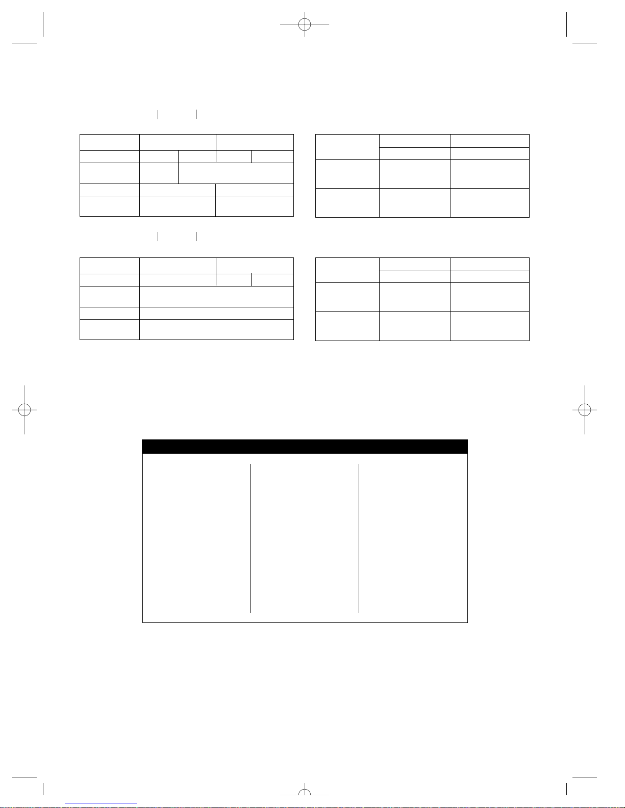
XR-2 Data Sheet
Model Name_____________________
Model Name_____________________
Frequency Chart
STEERING THROTTLE
TRAVEL ADJUST STR STL FWD REV
STEERING DUAL
RATE %
SUB-TRIM
SERVO
REVERSING
REV. NORM REV. NORM
VIII. FREQUENCY CHART
FREQUENCY(MHZ)CHANNEL FREQUENCY(MHZ)CHANNEL FREQUENCY(MHZ)CHANNEL
26.995...............................1
27.045...............................2
.095...............................3
.145...............................4
.195...............................5
.255...............................6
75.410.............................61
.430.............................62
.450.............................63
.470.............................64
.490.............................65
.510.............................66
75.530.............................67
.550.............................68
.570.............................69
.590.............................70
.610.............................71
.630.............................72
.650.............................73
.670.............................74
.690.............................75
.710.............................76
.730.............................77
.750.............................78
75.770.............................79
.790.............................80
.810.............................81
.830.............................82
.850.............................83
.870.............................84
.890.............................85
.910.............................86
.930.............................87
.950.............................88
.970.............................89
.990.............................90
Function Mode
TRIM STEERING THROTTLE
VALUES
STEERING Grip
DUAL Lever
RATE B %
BRAKE Grip
TRAVEL Lever
ADJUST A %
DirectMode
STEERING THROTTLE
TRAVEL ADJUST STR STL FWD REV
STEERING DUAL
RATE %
SUB-TRIM
SERVO
REVERSING
REV. NORM REV. NORM
Function Mode
TRIM STEERING THROTTLE
VALUES
STEERING Grip
DUAL Lever
RATE B %
BRAKE Grip
TRAVEL Lever
ADJUST A %
DirectMode
JR XR-2 7/15/99 8:35 AM Page 22
Page 23

23
er, servos, etc.). Do not return your system installed in a
model car, boat, etc.
3. Preferably, use the original carton/packaging (molded
foam container), or equivalent, to ship your system. Do not
use the system carton itself as a shipping carton—you
should package the system carton within a sturdy shipping
container using additional packing material to safeguard
against damage during transit. Include complete name and
address information inside the carton, as well as clearly writing it on the outer label/return address area.
4. Include detailed information explaining your operation of
the system and problem(s) encountered. Provide an itemized
list of equipment enclosed and identify any particular
area/function which may better assist our technicians in
addressing your concerns. Date your correspondence, and
be sure your complete name and address appear on this
enclosure.
5. Include you name, mailing address, and a phone number
where you can be reached during the business day.
6. Warranty Repairs.To receive warranty service you
must include your original dated sales receipt to verify your
proof-of-purchase date. Providing that warranty conditions
have been met, your radio will be repaired without charge.
7. Normal Non-Warranty Repairs.Should your repair
cost exceed 50% of the retail purchase cost, you will be provided with an estimate advising you of your options.
Within your letter, advise us of the payment method you prefer to use. The Horizon Service Center accepts VISA or
MasterCard, or we can return C.O.D. cash-only. If you prefer
to use a credit card, include your card number and expiration
date.
Mail your system to: Horizon Service Center
4105 Fieldstone Road
Champaign, IL 61821
Phone: (217) 355-9511
Warranty And Service
Information
Important Note: Be sure to keep your original dated sales
receipt in a safe place as you will be required to provide
proof of purchase date for the equipment to be serviced
under warranty.
Warranty Coverage
Your new JR Remote Control Radio System is warranted to
the original purchaser against manufacturer defects in material and workmanship for 365 days from the date of purchase.
During this period, Horizon Service Center will repair or
replace, at our discretion, any component that is found to be
factory defective at no cost to the purchaser. This warranty is
limited to the original purchaser of the unit and is not transferable.
This warranty does not apply to any unit which has been
improperly installed, mishandled, abused or damaged in a
crash, or to any unit which has been repaired or altered by
any unauthorized agencies. Under no circumstances will the
buyer be entitled to consequential or incidental damages.
This limited warranty gives you specific legal rights; you
also have other rights which may vary from state to state. As
with all fine electronic equipment, do not subject your radio
system to extreme temperatures, humidity or moisture. Do
not leave it in direct sunlight for long periods of time.
Repair Service Directions
In the event that your JR radio needs service, please follow
the instructions listed below.
1. Check all on/off switches to be sure they are off. This will
speed the repair process of checking battery condition.
2. Return your system components only (transmitter, receiv-
JR XR-2 7/15/99 8:35 AM Page 23
Page 24

© Copyright 1998, Horizon Hobby Distributors, Inc.
JR XR-2 7/15/99 8:35 AM Page 24
 Loading...