

Page 1
©JRI 1
USER MANUAL
SPY RF T+
06246D
Page 2

©JRI 2
TABLE OF CONTENTS
I. INTRODUCTION ............................................................................................................................................................ 3
a) Equipment ................................................................................................................................................................................. 3
b) Symbols ..................................................................................................................................................................................... 3
II. PRESENTATION ............................................................................................................................................................ 3
a) Display ....................................................................................................................................................................................... 3
b) Complementary information .................................................................................................................................................... 4
III. INSTALLATION RECOMMANDATIONS ....................................................................................................................... 4
a) Perturbations sources .............................................................................................................................................................. 4
b) Installation recommendations ................................................................................................................................................. 4
IV. USE ................................................................................................................................................................................ 5
a) Stop ............................................................................................................................................................................................ 5
b) Start ............................................................................................................................................................................................ 5
c) Waiting mode ............................................................................................................................................................................ 5
d) Configuration............................................................................................................................................................................. 5
e) Measurement start .................................................................................................................................................................... 5
f) Automatic start .......................................................................................................................................................................... 5
g) Manual start ................................................................................................................................................................................6
h) Alarm visualisation ....................................................................................................................................................................6
i) Measurement stop .................................................................................................................................................................... 7
j) Auto control or top zone .......................................................................................................................................................... 7
k) Leds and pushbutton actions functioning .............................................................................................................................. 7
V. FEATURES .................................................................................................................................................................... 8
VI. CAPACITY OF OPERATION DATA SHEET ................................................................................................................. 9
VII. WARRANTY ................................................................................................................................................................. 10
VIII. MAINTENANCE CONTRACT ...................................................................................................................................... 10
IX. ENVIRONMENT PROTECTION ................................................................................................................................... 10
Page 3
©JRI 3
I. INTRODUCTION
Congratulations, you own a SPY RF T+ ! This device is equipped with 1 internal sensor. It enables you to record the ambient
temperature and to transfer wirelessly the recorded data by radio frequency to a PC.
The SPY RF T+ complies with EN 12830.
a) Equipment
1 SPY RF T +
1 user manual
b) Symbols
II. PRESENTATION
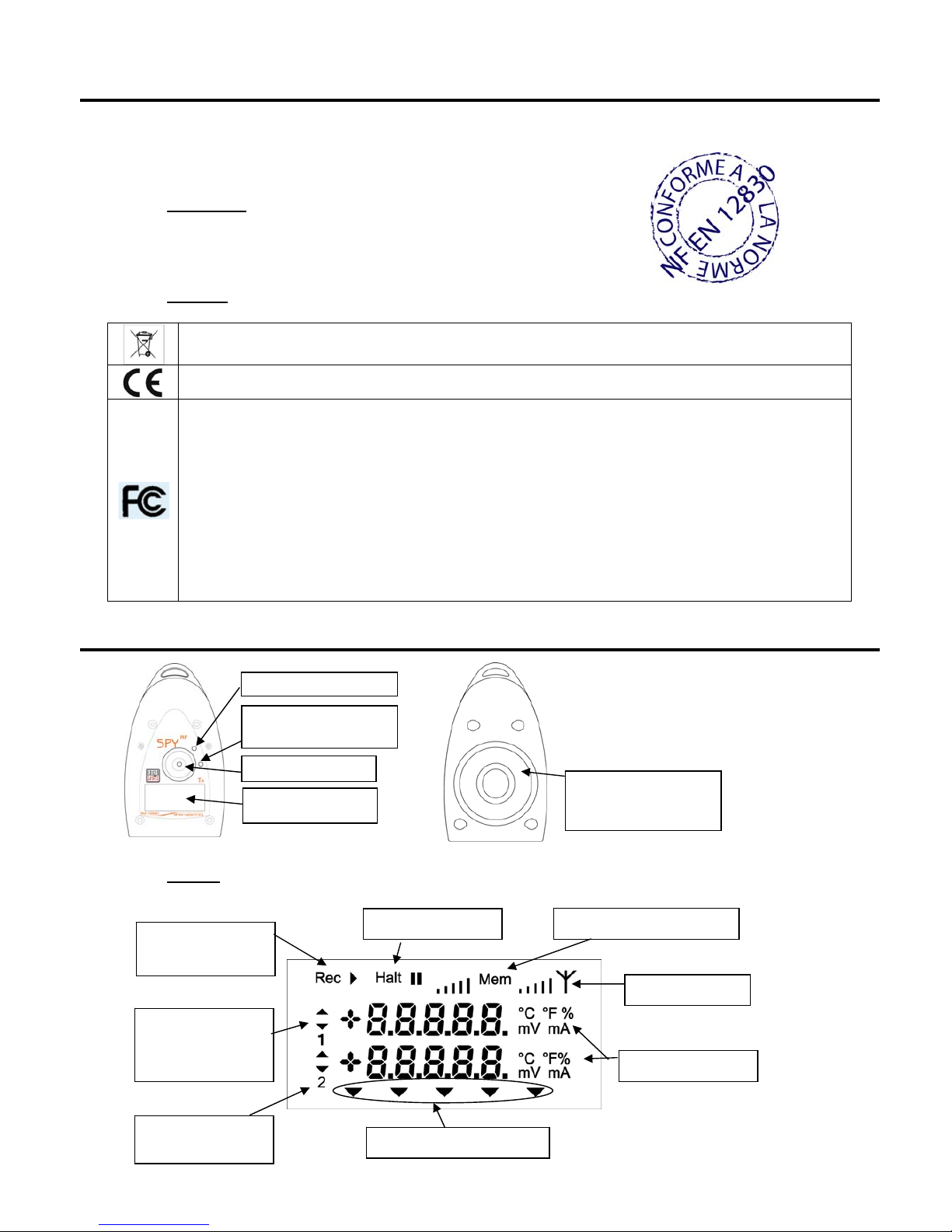
a) Display
RECYCLING : do not throw in a rubbish dump or in a domestic waste container. Comply to the regulation to throw away the
device.
CE MARKING : this equipment is certified to comply with the European regulation for the electric security, inflammability,
disturbing radiation emission and immunity to surrounding electric disturbances.
FCC ID : W45 03330
This device complies with Part 15 of the FCC Rules. Operation is subject to the following two conditions: (1) this device may
not cause harmful interference, and (2) this device must accept any interference received, including interference that may
cause undesired operation
In accordance with FCC requirements, changes or modifications not expressly approved by JRI could void the user's
authority to operate this product.
NOTE: This equipment has been tested and found to comply with the limits for a Class A digital device, pursuant to Part 15
of the FCC Rules. These limits are designed to provide reasonable protection against harmful interference when the
equipment is operated in a commercial environment. This equipment generates, uses and can radiate radio frequency
energy and, if not installed and used in accordance with the instruction manual, may cause harmful interference to radio
communications. Operation of this equipment in a residential area is likely to cause harmful interference in which case the
user will be required to correct the interference at his own expense.
Non-programme
d
Recording mode
Overpassed
thresholds
indicators
Channel N°
Waitingmode
Measurement
Memory status
Radio signal
Recording led(green)
Push button
Alarm led (red)
Dilatation cap to
absorbe variation of
p
ressure
Page 4
©JRI 4
b) Complementary information
III. INSTALLATION RECOMMANDATIONS
The Spy RF is a recorder of physical parameters able to communicate wirelessly with the operating software SIRIUS.
The wireless communication is based on radio frequency. As we are daily in contact with it (radio, TV…) it is easy to think
that it always works. This true if basic rules on the positioning of recorders are respected because wireless communication is
subject to perturbations.
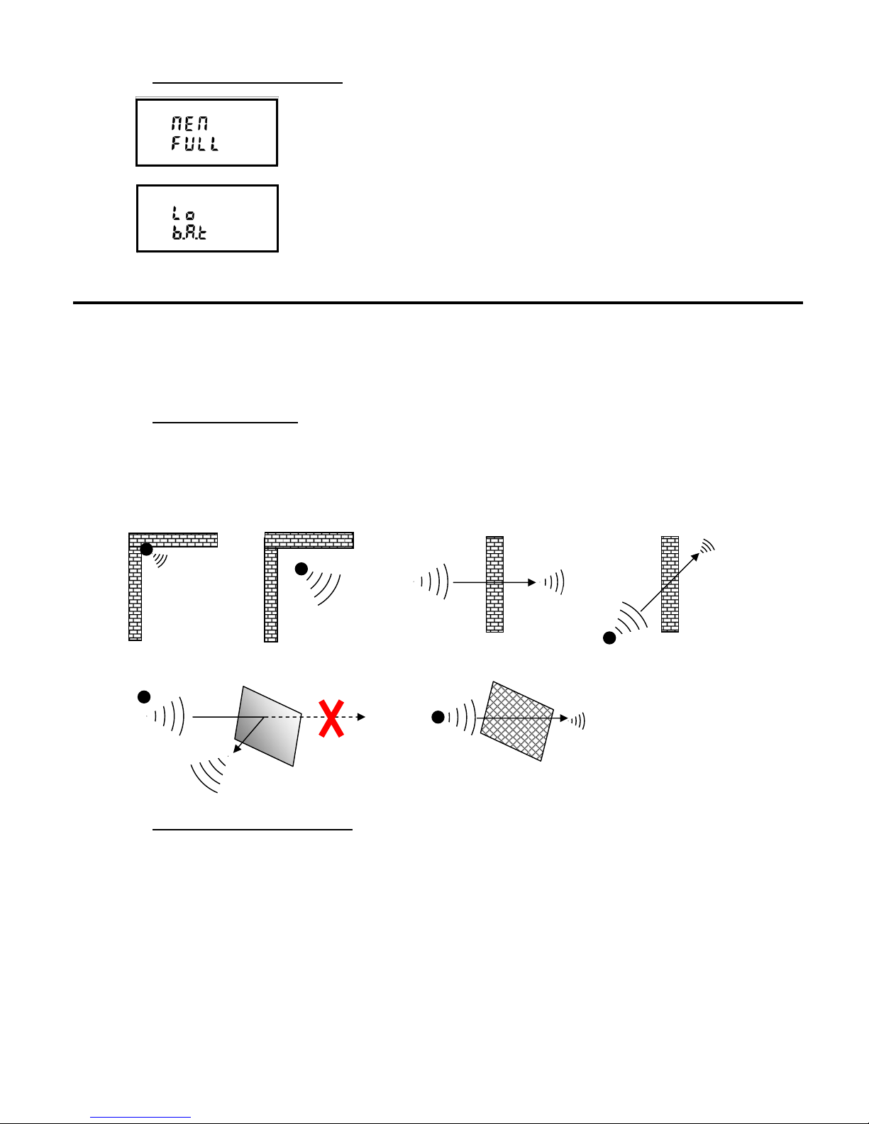
a) Perturbations sources
Presence of obstacles in the way of the waves between the Spy RF ModeM and the Spy Rf (wall, ceiling, person,
furniture…) or close to the antenna.
Obstacles thickness in the way of the waves. The absorption is more important in diagonal as perpendicularly
Waves cannot pass through full metallic walls. On the other hand, a perforated wall allows the waves passing with
attenuation
b) Installation recommendations
Place the devices at ~2m height and around 30 to 40cm from the ceiling to avoid obstacles and moving persons.
If possible, place the Spy RF in central position regarding the Spy RF recorders.
Try to place them preferably at sight of each other.
On the wall, it is preferable to them aside by using the special bracket (ref 08512) of the catalog.
Place the antenna above the top the monitored unit (fridge, incubator, oven, cold rooms…),.
Never place the Spy RF horizontally.
If some difficulties persist, it is possible to use Spy RF RelaY (repeaters) or to connect another Spy RF ModeM to the
Ethernet network (LAN).
Full memory. You must transfer the data to your PC.
Low battery. You must change the battery.
Page 5
©JRI 5
IV. USE
a) Stop
When you receive it, your SPY RF is stopped. Only the time clock is active. It can neither emit nor receive anything.
b) Start
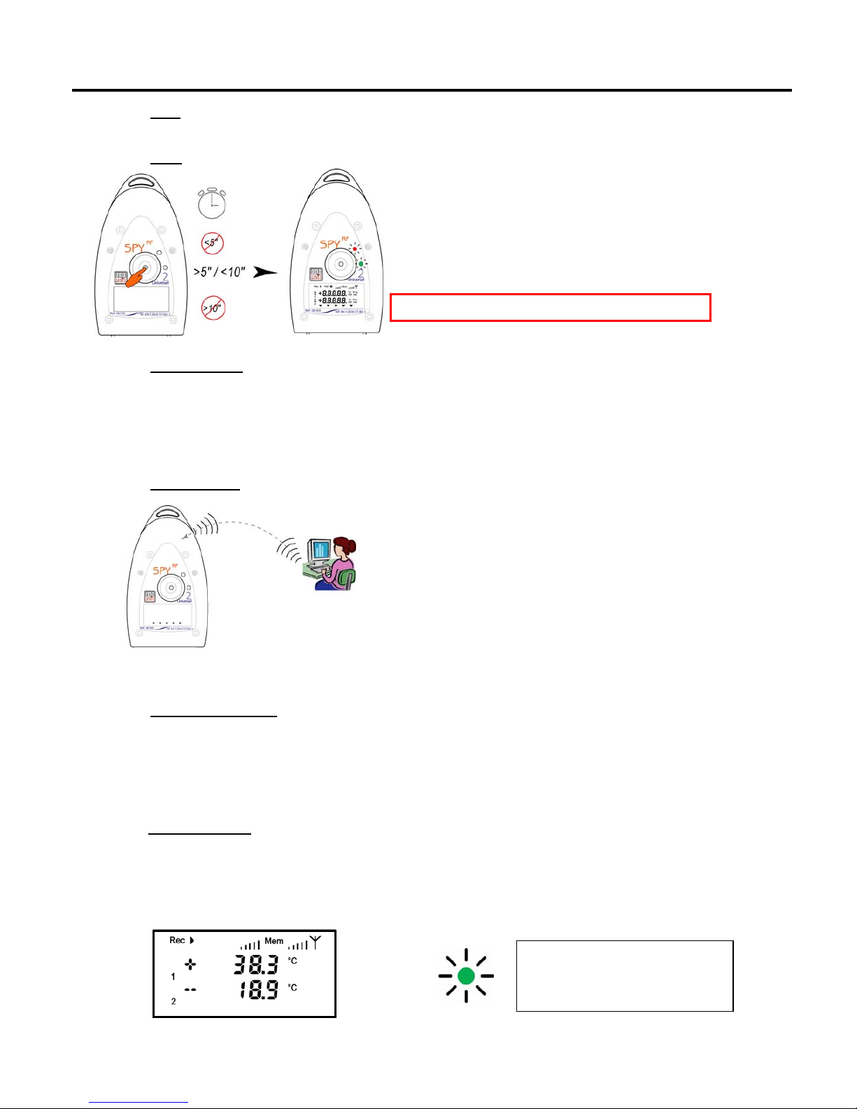
To start your SPY RF, please press between 5 and 10” on the
button:
- the 2 LEDs are on and flash at the same time
- all the display segments are also on
- SPY RF is now in waiting mode
Remark: If you press >10’’ => no effect => remains off
c) Waiting mode
The SPY RF is ready to receive a configuration or to start a new recording session.
The symbol “Halt” is on: no measures in progress.
Use the pushbutton to start.
d) Configuration
SPY RF configuration is done from the Sirius software and then
transferred into your SPY RF by radio frequency.
e) Measurement start
The SPY RF has 2 starting mode:
automatic start
manual start
f) Automatic start
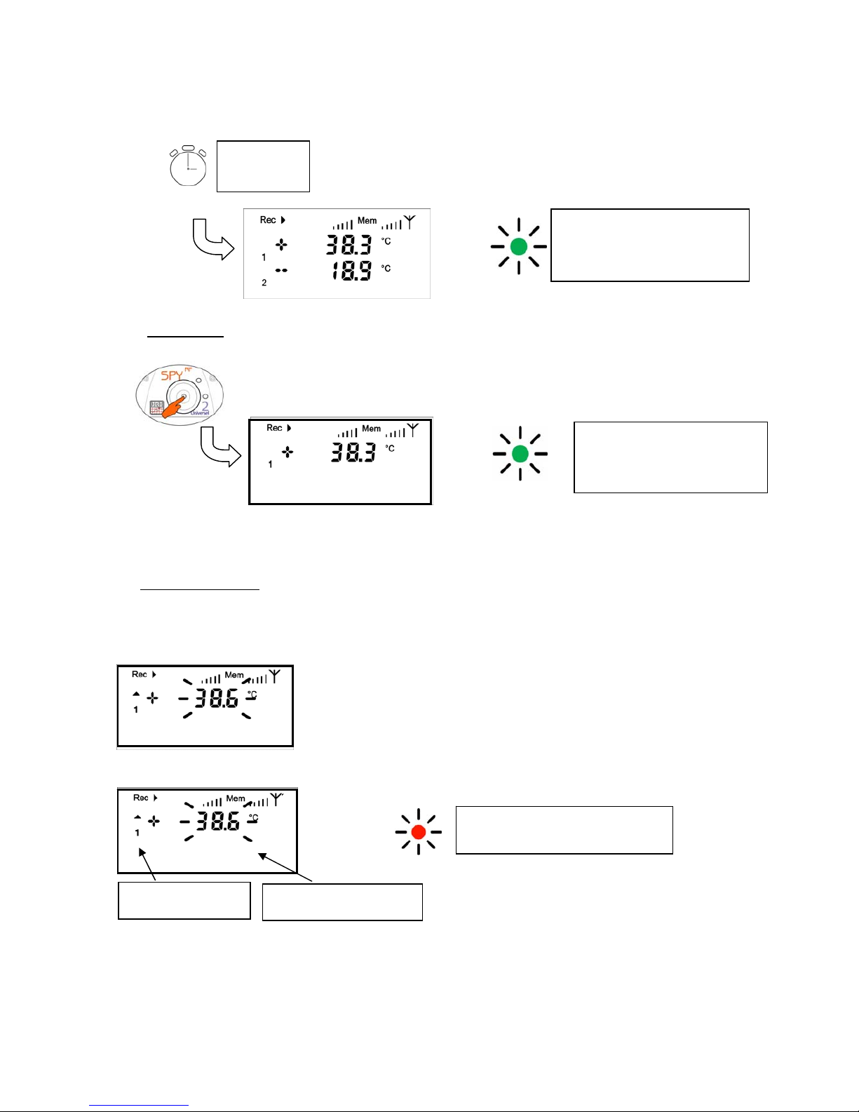
Your SPY RF starts recording:
automatically when the configuration is transferred,
It displays the temperature in °C degrees, channel number, measurement unit and memory status.
The green LED flashes every minute.
+
Working LED (green):
2’’ => starting measurements
then flashes every 1 minute
Page 6
©JRI 6
The temperature, threshold indicator, channel number and a red LED flashes every 15 sec in case the
threshold limit is overpassed.
at a programmed date and time:
g) Manual start
Press shortly on the pushbutton
It displays the temperature in °C degrees, channel number, measurement unit and memory status.
The green LED flashes every minute.
h) Alarm visualisation
The SPY RF is equipped with different alarm indicators, when a threshold limit is overpassed.
Pre alarm
Alarm
+
+
Alarm LED (red):
Flashes every 15’’.
Threshold indicator
High or low
Value measured
Flashes every 15”
dd / mm / yy
hh / mm / ss
+
Working LED (green):
2’’ => starting measurements
then flashes every 1 minute
Working LED (green):
2’’ => starting measurements
then flashes every 1 minute
Page 7
©JRI 7
+
T° OK (voyant vert)
s’allume pendant 10’’.
+
Témoin d’alarme (rouge)
s’allume pendant 10’’.
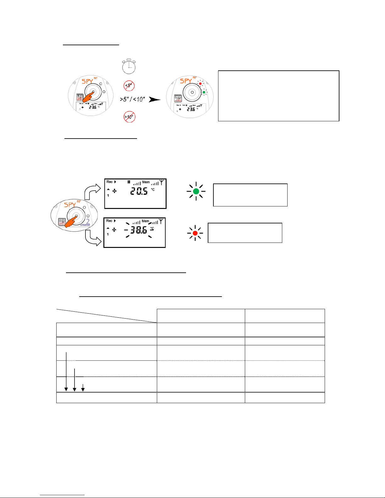
i) Measurement stop
Depending on the configuration, the SPY RF can stop recording or not. The different options are:
j) Auto control or top zone
The type of action depends on the SPY RF configuration.
TOP ZONE = Transport mode and AUTO CONTROL = Storage mode
This function enables you to customise an action of measurement check-up. You just have to press shortly on
the pushbutton.
The action is recorded and will appear on the curve when you process the data with your software Sirius.
k) Leds and pushbutton actions functioning
The green led is on 2’’ when the measurement starts and then flashes each 1’ in recording mode.
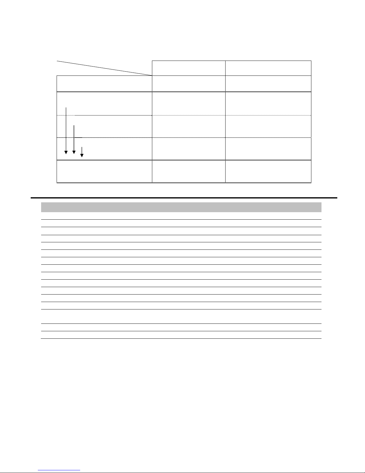
Specials functioning regarding the recorder using mode
Device set up in storage mode
Pushbutton pressing
Mode
< 5" 5’’> pressing <10’’
OFF -
The 2 leds are on and
flash at the same time.
Starting measurements
Pushbutton
Green led 2" = beginning of
measurements
-
Delayed (date & time) - -
Immediately
- -
Mesure
Green led 10" = auto control -
To stop your SPY RF, press between 5
and 10” on the button:
- The 2 LEDs are on and then flash
alternatively.
- The screen goes off, Halt goes on.
Page 8
©JRI 8
Device set up in transportation mode
V. FEATURES
FEATURES SPY RF T+
Measurement range -30 +70°C
Number of channels 1 internal
Type of input
PTC
Accuracy ±0,4°C from -20 to +30°C / ±0,5°C out side
Recording interval 30s to 90 min
Memory size 10 000 measurements
Operating conditions -30 +70°C
Temperature for storage -40 + 85°C
Radio range (in free field) 1 km
Radio band 868MHz – 902MHz
Battery lifetime 5 years
Dimensions 123x69x30mm
Protection level (1h at 1m depth) IP68
EN 12 830 compliance Yes : this devis must be regularly checked
according to EN 13 486 (1 time per year recommended)
CE ERM compliance EN 301 489 / EN 61000 / EN 61010EN 55022 / EN 300 220
FCC compliance FCC part 15
Pushbutton pressing
Mode
< 5" 5"<appui>10"
Off -
The 2 leds are on and flash at
the same time.
Starting measurements
Pushbutton
Green led 2" = beginning of
measurements
-
Delayed (date & time)
The 2 leds are on and flash at
the same time = Waiting for
starting measurements
Immediately
-
The 2 LEDs are on and then
flash alternatively = ending
measurements
Mesure
Green led 10" = Top zone
The 2 LEDs are on and then
flash alternatively = ending
measurements
Page 9
©JRI 9
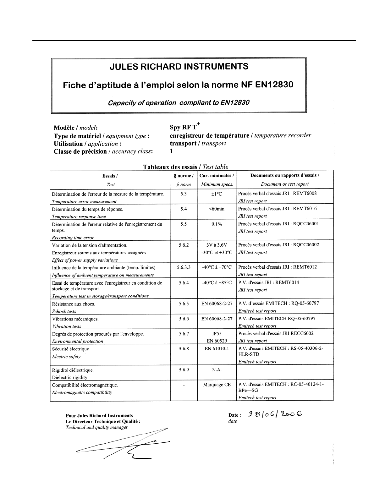
VI. CAPACITY OF OPERATION DATA SHEET
Page 10

VII. WARRANTY
JRI products carry a one year warranty a nd guarantee ag ainst defects in their compon ents or workmans hip.
During this period if any product supplied by the Company proves on inspection to be defective, the Company will at its own option
replace the same or refund to the Buyer the price of the product.
In no circumstances will JRI' liability exceed the price of the product paid by the buyer or the cost of replacement.
JRI shall not in any event be liable to the Buyer for any i ndirect or consequential loss or damage costs or expenses whatsoever which
might arise out of or in connection with the supply of the product or its consequent use.
Consequently, the products warrantee and guarantee spe cified above, does not cover dam age caused by fair wear and tear, a bnormal
storage conditions, incorrect use, accidental misuse, abuse, neglect, misapplication or modification, or use with non-JRI'
hardware/software. No warranty of fitness f or a particular pur pose is offer ed and the us er assumes the e ntire risk of usi ng the produc t.
In line with our policy of continuous development, we reserve the right to amend our product specific ation witho ut prior notice.
VIII. MAINTENANCE CONTRACT
How to optimize your radio frequency installation?
RF measuring systems communicate by radio frequency. However, there may be several factors that can modify the radio ways
already defined, such as moving from a building, adding walls, … Radio frequency requires thus a periodical follow up performed by
specialists.
That’s why JRI has created maintenance contracts. We bring yo u a global solution whi ch makes your maint enance easi er. This overall
service offer includes maintenance an d also metrolog ical services, whi ch ensure yo u that your syst em is fully perform ant.
You won’t worry about your devices maintenance anymore !
With this maintenance contract you will benefit for a m inimal period of 2 year s from the foll owing advant ages:
- material verification once or twice a year
- warranty extension
- telemaintenance
- telephone assistance
+33 (0) 892 680 933 (0,282 € HT/min)
- material replacement on site or by return in our ma nufacture
- metrological certificates: verification of meas urement accuracy
- access to new software versions and u pdates
- on-site intervention time within 3 open days after pr oblem identific ation by o ur experts
IX. ENVIRONMENT PROTECTION
JRI recommends to our customers to throw away their measurin g and recording d evices which are un serviceable and/or beyond repair
in a way that is appropriate to environm ent protecti on. Insofar as t he product ion of wast e cannot be avoided, it is best to re-use them by
proceeding with adapted recycling depending on the material us ed and co nsidering the environment pr otection.
RoHS Directive
The ROHS European Directive rules and limits the presence of hazardous substances in electrical and electronic equipments (EEE).
In the article 2, the scope of this Directive excludes "9. Monitoring and Control Instruments" and our produ cts are part of this category.
Nevertheless, our company has decided to apply the whole dispositions of this Directive for all our new electronic devices which will
comply to this 2002/95/CE Directive.
 Loading...