

Page 1
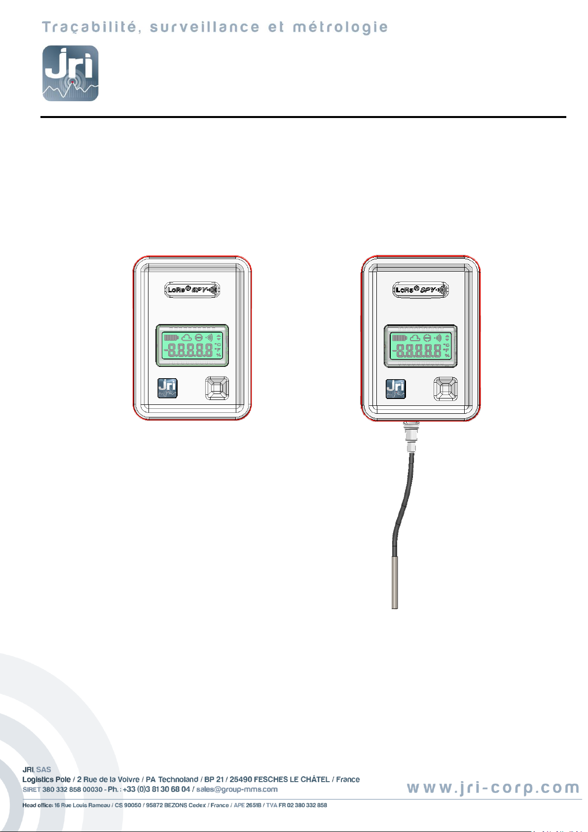
USER GUIDE
LoRa® SPY
Ref : 11819G
Page 2

TABLE OF CONTENTS
I. INTRODUCTION ........................................................................................................................................ 3
a) Product contents ....................................................................................................................................................... 3
b) Symbols ...................................................................................................................................................................... 3
II. INSTALLATION RECOMMENDATIONS ........................................................................................................ 3
a) Sources of disturbances or attenuation .................................................................................................................... 3
b) Positioning ................................................................................................................................................................. 4
III. PRESENTATION ........................................................................................................................................ 4
a) Control unit ................................................................................................................................................................ 4
b) LCD display ................................................................................................................................................................. 5
c) Mounting ................................................................................................................................................................... 5
IV. USE ..................................................................................................................................................... 5
a) OFF state .................................................................................................................................................................... 5
b) Activation ................................................................................................................................................................... 5
c) Turning Off ................................................................................................................................................................. 6
d) Actions on the touch-sensitive button ...................................................................................................................... 6
V. PROBE CONNECTIONS .......................................................................................................................... 6
VI. BATTERY REPLACEMENT .......................................................................................................................... 7
VII. CHARACTERISTICS .................................................................................................................................... 7
a) Compliance .............................................................................................................................................................. 11
VIII. MAINTENANCE ................................................................................................................................... 11
IX. SUITABILITY FOR USE ................................................................................................................................. 12
X. GUARANTEE ........................................................................................................................................... 16
XI. MAINTENANCE CONTRACT ...................................................................................................................... 16
XII. ENVIRONMENTAL PROTECTION .............................................................................................................. 16
©JRI 2
Page 3
I. INTRODUCTION
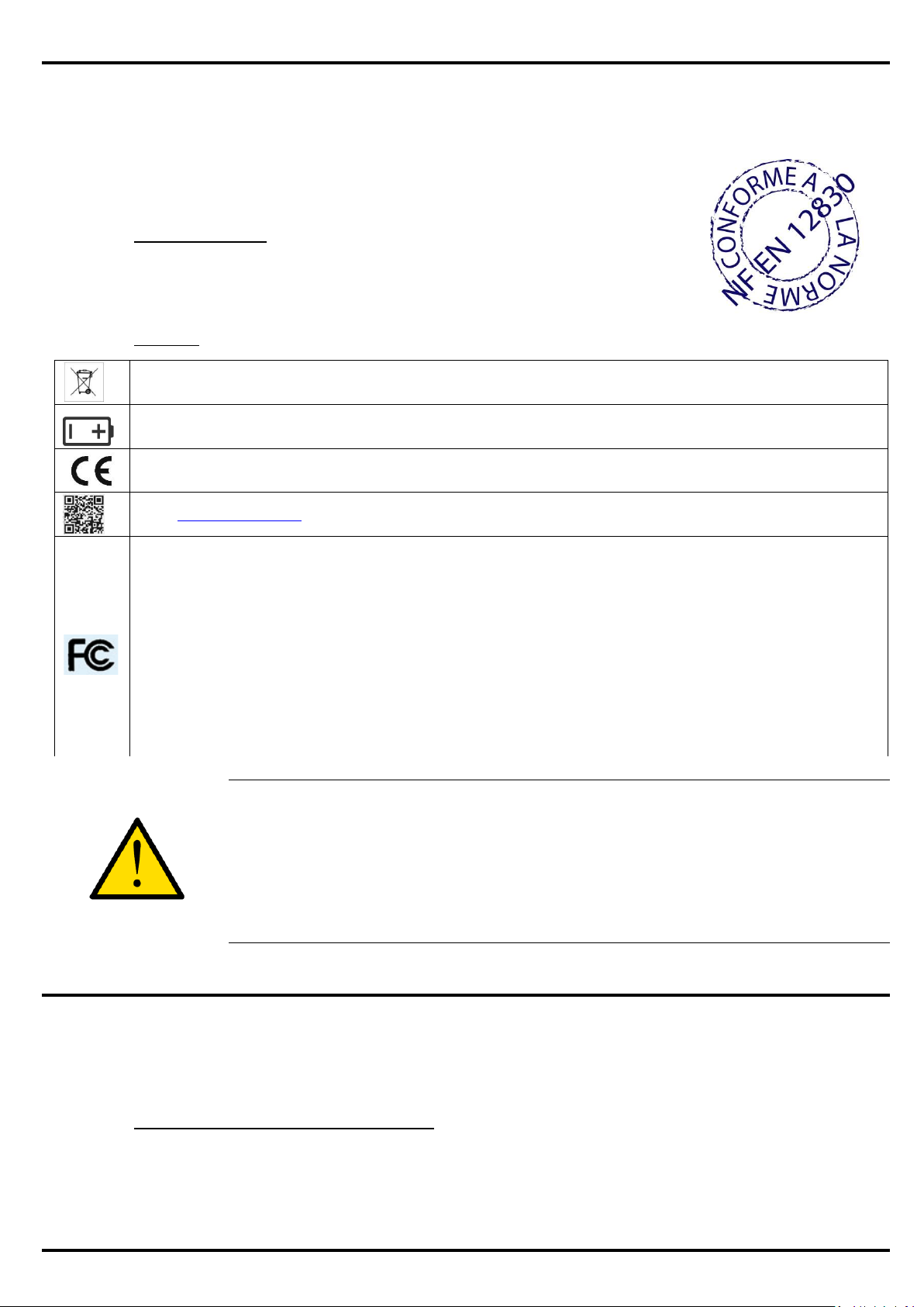
RECYCLING: do not dispose of in a refuse dump or waste disposal bin. Comply with existing legislation for disposal.
Power source: this device is powered by a 3.6VDC type AA lithium battery (§ ch. V).
CE LABELING: this device is certified to conform to European regulations for electrical safety, flammability, disruptive
electromagnetic emissions, and immunity to environmental electrical disturbances.
Opens www.jri-mysirius.com.
FCC ID : W4512267
This device complies with Part 15 of the FCC Rules. Operation is subject to the following two conditions: (1) this device may not
cause harmful interference, and (2) this device must accept any interference received, including interference that may cause
undesired operation
In accordance with FCC requirements, changes or modifications not expressly approved by JRI could void the user's
authority to operate this product.
NOTE: This equipment has been tested and found to comply with the limits for a Class A digital device, pursuant to
Part 15 of the FCC Rules. These limits are designed to provide reasonable protection against harmful interference
when the equipment is operated in a commercial environment. This equipment generates, uses and can radiate radio
frequency energy and, if not installed and used in accordance with the instruction manual, may cause harmful
interference to radio communications. Operation of this equipment in a residential area is likely to cause harmful
interference in which case the user will be required to correct the interference at his own expense.
The LoRa® SPY is a recorder capable of measuring 1 or 2 physical quantities (T / TH or other quantity depending
on the model) and transmitting by radio to monitoring software hosted on a platform. The radio transmission
uses the LoRa® long-distance network.
The LoRa® SPY (T0, T1 andT2) comply with EN 12830 and compatible with EN 13486 which
defines procedures for periodic verification.
a) Product contents
1 LoRa® SPY
1 User guide
b) Symbols
Do not use the device under conditions other than those described in the technical
characteristics
Risk of fire or explosion in the case of improper use:
- Recharging of the battery
- Short circuiting of the battery
If the device is used in a manner not specified by the manufacturer, the protection
provided by the device may be compromised.
II. INSTALLATION RECOMMENDATIONS
The LoRa® SPY is a recorder which communicates by radio with software hosted on a Web platform via the
LoRa® long-distance public network or private network using a LoRa® Gateway. To ensure optimal radio
transmission, a certain number of recommendations must be respected, as any wireless transmission is subject
to disturbances.
©JRI 3
a) Sources of disturbances or attenuation
The presence of obstacles in the wave path around the LoRa® SPY or between the LoRa® SPY and
the Gateway in case of use (wall, furniture, people…) or near the antenna.
Page 4
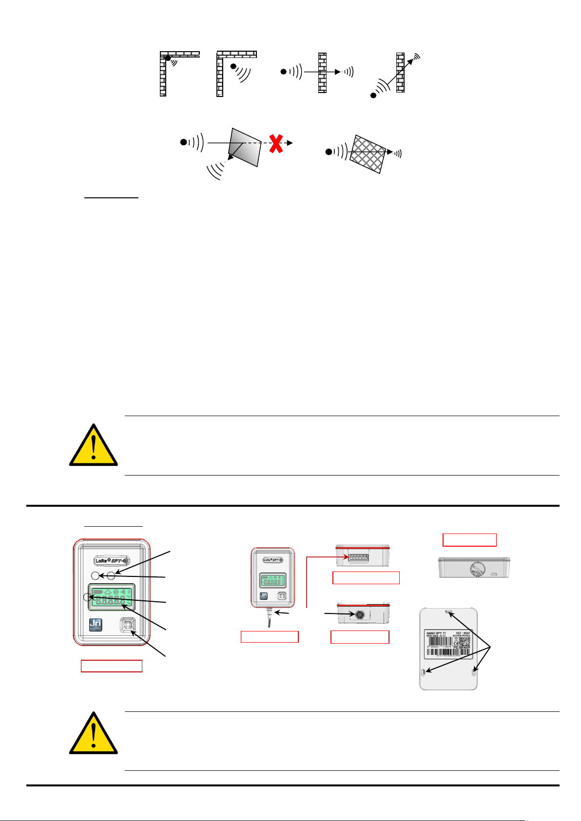
The thickness of an obstacle in the wave path. The attenuation is greater diagonally than
Touch-sensitive
button
Status LED
LCD display
Light sensor (T1 only)
Models T1/TH1
Models T2/T3
Internal sensor
Digital Model
TH3/U Models
Sensor
Battery access
All Models
Mounting
eyelets
perpendicularly
A solid metal wall will not allow transmission by radio. A perforated metal wall will allow waves
to pass while attenuating them.
b) Positioning
The LoRa® SPY units can be placed either inside or outside the enclosures.
For installations outside the enclosure, mount the units sufficiently high on the walls to avoid
interference with obstacles and foot traffic.
The LoRa® SPY uses the LoRa® public network.
Never place the LoRa® SPY unit horizontally.
If difficulties persist use the LoRa® SPY with remote probe in order to position it in a zone of radio
coverage.
Also, some specific recommendations for exposure to magnetic fields must be followed : This
equipment complies with FCC’s radiation exposure limits set forth for an uncontrolled
environment under the following conditions :”
o This equipment must be installed and operated such that a minimum separation distance of 20cm
is maintained between the radiator (antenna) and user’s/nearby person’s body at all time.
o This transmitter must not be co-located or operating in conjunction with any other antenna or
transmitter
To ensure your safety during installation or an intervention on a device placed in a high
position, use proper equipment which is in good condition and provides adequate
stability, wear appropriate, non-slip shoes and install warning signs around the work
area if the intervention takes place in an area of foot traffic.
III. PRESENTATION
a) Control unit
Le LoRa®SPY T1 is equipped with a detector of presence or absence of light.
When the LoRa®SPY unit is enclosed (in the dark) the measurements are no longer
displayed (wheaeas the battery level, the RSSI and the network indicators still are) and
its status LED continues to flash.
©JRI 4
Page 5
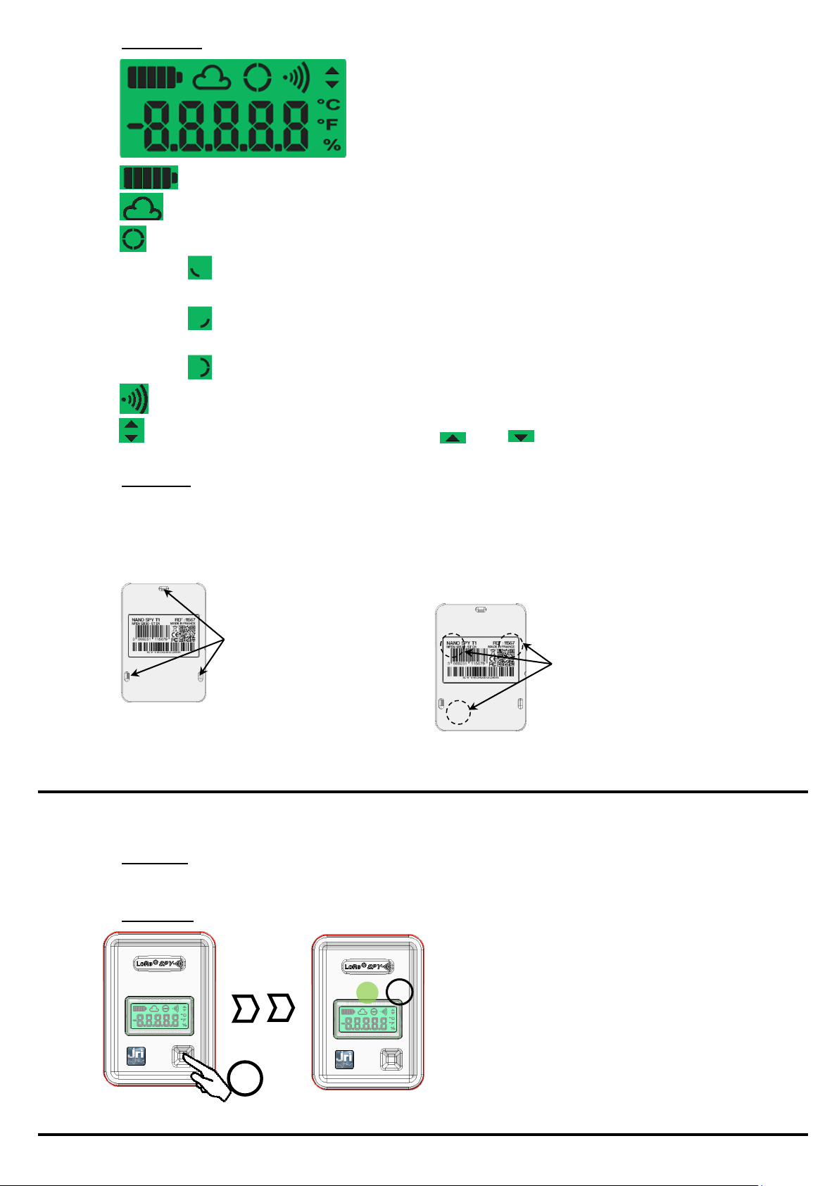
b) LCD display
Using a tie wrap to attach it to the
monitored product
Magnetically
The LoRa® SPY has 3 internal magnets for mounting
on magnetic metal walls.
Mounting
eyelets
Magnets
3’’
3’’
Battery level indicator
MySirius connection indicator
LoRa® networkconnection indicator
RSSI radio reception level indicator
Threshold overrun indicator ( High, Low)
c) Mounting
Searching factory network
blinking : Searching for LoRa® network
Fixed : LoRa® network found
Empty: LoRa® Network not found
Connected to MySirius
The LoRa® SPY can be mounted in 2 different ways
IV. USE
The LoRa® SPY can only be used with the My Sirius software hosted on a Web platform.
a) OFF state
As delivered, the LoRa® SPY is turned off. It can neither emit nor receive signals.
b) Activation
©JRI 5
Page 6
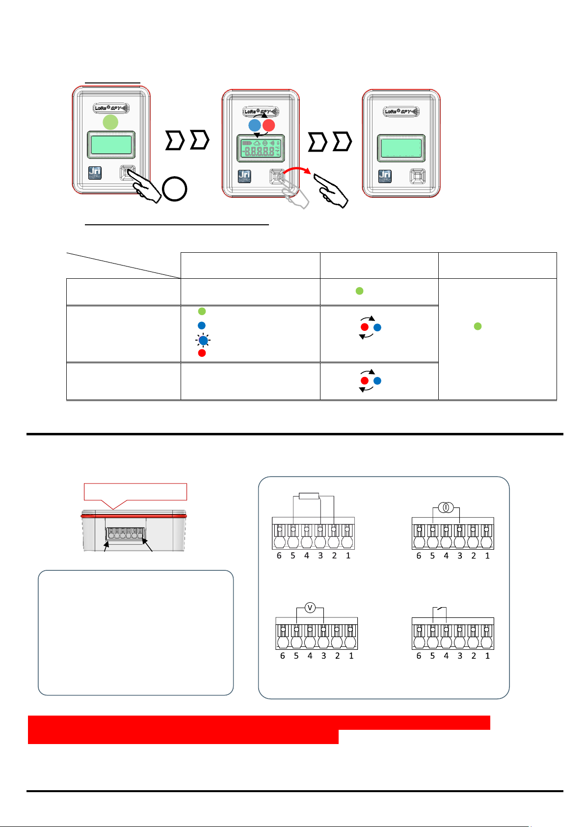
Once activated, the LoRa® SPY measures and transmits its measurements to My Sirius, at the frequency defined
Touch duration
Mode
< 3s
> 3s
>8s
Activation - during 3s
during 3s
The LoRa SPY remains
activated
Measurement
1s = OK
1s = Technical alarm
3x1s = OK but paused
1s = In alarm state
Off
Off
-
Off
Front face / Display
4-20mA input
Resistive sensor
input
0-1V input
Logic, count input
3’’
in MySirius, then flashes regularly as a function of its status.
c) Turning Off
d) Actions on the touch-sensitive button
V. PROBE CONNECTIONS
The Universal LoRa® SPY has a quick connector facilitating the installation of different types of sensors. The
sensors can be disconnected from the recorder for their replacement or for changing the recorder itself
NC
Resistive sensor power
Analog input (Resistance
Current Voltage)
Logic, count or frequency input
GND (0V)
NV
/!\ Connect only sensors which are compatible with the technical characteristics of the devices
Sensor default detection is not possible in 0-20mA and 0-1V.
©JRI 6
Page 7
VI. BATTERY REPLACEMENT
LoRa® SPY T0 - Temperature (internal probe)
HIM
: 1 LED RGB + 1 touch-sensitive button
Communication
: LoRa® 868MHz or 915MHz*
Memory
: 10 000 time-stamped measurements
Sensor
: PT100 sensitive element inside unit
Operating range
: -35+85°C
Measurement range
: -35+85°C
Accuracy, standard version
: ±0.5°C from -20°C to +30°C / ± 0.8°C outside this range
Resolution
: 0.01
IP rating
: IP 68
Frequency of recording and
transmission
: adjustable from 1min to 24h
Frequency of measurement
: 1 or 5 min
Response time
: ~ 15 min. to 90% of the variation
Power source
: 3,6V Lithium battery– 2 to 4 years autonomy depending
on use
Case
: Polycarbonate – Food safe – Without magnets
Dimensions
: 87 mm x 64 mm x 25 mm
Weight
: ~ 100g
LoRa® SPY T1 - Temperature (internal probe)
HIM
: 1 LED RGB + 1 touch-sensitive button + 1 LED Display
Communication
: LoRa® 868MHz or 915MHz*
Memory
: 10 000 time-stamped measurements
Sensors
: PT100 sensitive element inside unit
Light presence sensor
Operating range
: -30+70°C
Measurement range
: -30+70°C
Accuracy, standard version
: ±0.4°C from -20°C to +40°C / ± 0.5°C outside this range
Resolution
: 0.01
IP rating
: IP 68
Frequency of recording and
transmission
: adjustable from 1min to 24h (15 min in standard use)
Frequency of measurement
: 1 or 5 min
Response time
: ~ 15 min. to 90% of the variation
Power source
: 3,6V Lithium battery– 2 to 4 years autonomy depending
on use
Case
: Polycarbonate – Food safe
Dimensions
: 87 mm x 64 mm x 25 mm
Weight
: ~ 100g
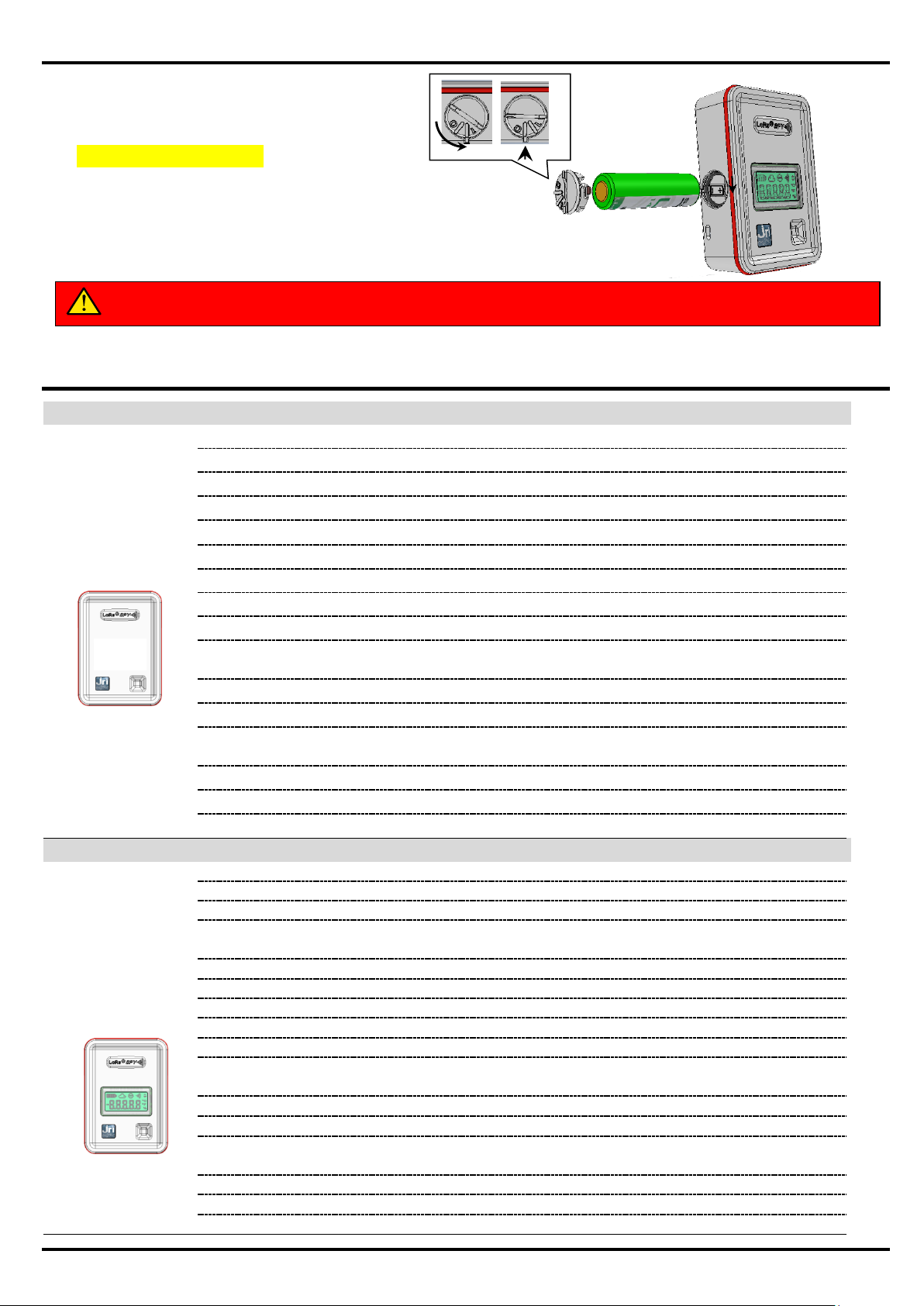
KEEP THE BATTERY AWAY FROM FIRE; DO NOT ATTEMPT TO RECHARGE OR SHORT-CIRCUIT IT
ONLY USE BATTERIES* SUPPLIED BY JRI (REF : 11596)
Removing the battery
Open the battery cover with a suitable
object (2cts coin) to align the marks
(/!\0 = Open ; 1= Closed)
Remove the battery from its lodging
Replacing the battery
Put the new battery in place respecting
the polarity
*Recommended battery: Saft LS14500 type AA 3.6V 2250mAh
VII. CHARACTERISTICS
©JRI 7
Page 8
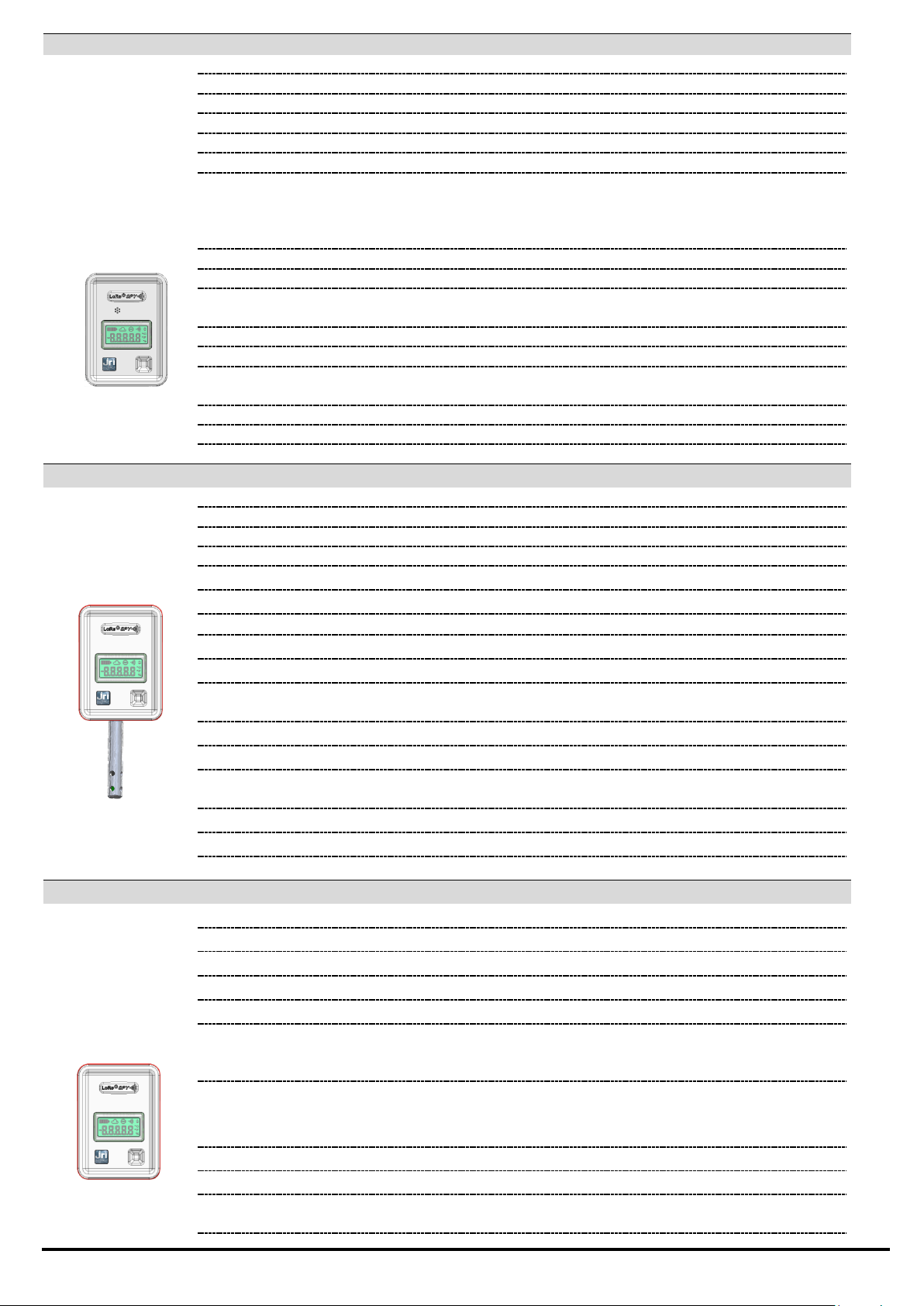
LoRa® SPY TH1 - Thermo-Hygro Internal
HIM
: 1 RGB LED + 1 touch-sensitive button + 1 LCD display
Communication
: LoRa® 868MHz or 915MHz*
Memory
: 10 000 time-stamped measurements
Sensor
: Inside control unit
Operating range
: -30+70°C
Measurement range
: -30+70°C and 0 – 100% RH
Accuracy, standard version
Temperature
Humidity at T° between 15 and 25°C
: ± 0.4°C from -20 C° to +40°C / ± 0.5°C outside this range
±2% HR from 20% to 80%
±4% HR from 0 to 20% and 80% to 100%
Resolution
: 0.01
IP rating
: IP 40
Frequency of recording and
transmission
: adjustable from 1 min to 24h (15 min in standard use)
Frequency of measurement
: 1 or 5 min
Response time
: ~ 5 min. to 90% of the variation
Power source
: 3,6V Lithium battery– 2 to 4 years autonomy depending
on use
Case
: Polycarbonate – Food safe
Dimensions
: 87 mm x 64 mm x 25 mm
Weight
: ~ 100g
LoRa® SPY N Digital
HIM
: 1 RGB LED + 1 touch-sensitive button + 1 LCD display
Communication
: LoRa® 868MHz or 915MHz*
Memory
: 10 000 time-stamped measurements
Sensor
: External to control unit
Operating range
: -30+70°C
Measurement range
: according to the type of JRI digital probe
Accuracy, standard version
: Accuracy of the JRI digital probes
Resolution
: 0.01
IP rating
: IP 40
Frequency of recording and
transmission
: adjustable from 1min to 24h (5min in standard use)
Frequency of measurement
: 1 or 5 min
Response time
: Depending of the digital probe used
Power source
: 3,6V Lithium battery– 2 to 4 years autonomy depending
on use
Case
: Polycarbonate – Food safe
Dimensions
: 87 mm x 64 mm x 25 mm
Weight
: ~ 100g
LoRa® SPY TH3 – Precision Thermo-Hygro
HIM
: 1 RGB LED + 1 touch-sensitive button + 1 LCD display
Communication
: LoRa® 868MHz or 915MHz*
Memory
: 10 000 time-stamped measurements
Sensor
: External to control unit
Operating range
: -30 +70°C
Probe measuring range
Standard
Industrial
: -40 +60°C and 0-100%HR
: -100 +200°C configurable and 0-100%HR
Probe accuracy at 23°±0,5°C
Standard
Industrial
Temperature : ± 0,1°C / Humidity : 0,8%RH
Temperature : ± 0,2°C / Humidity : 0,8%RH
Resolution
: 0.01
IP rating
: IP 40
Frequency of recording and
transmission
: adjustable from 1min to 24h (5min in standard use)
©JRI 8
Page 9
Frequency of measurement
: 1 or 5min
Response time
: ~ 2 min. to 90% of the variation
Power source
: 3,6V Lithium battery– 2 to 4 years autonomy depending
on use
Case
: Polycarbonate – Food safe
Dimensions
: 87 mm x 64 mm x 25 mm
Weight
: ~ 100g
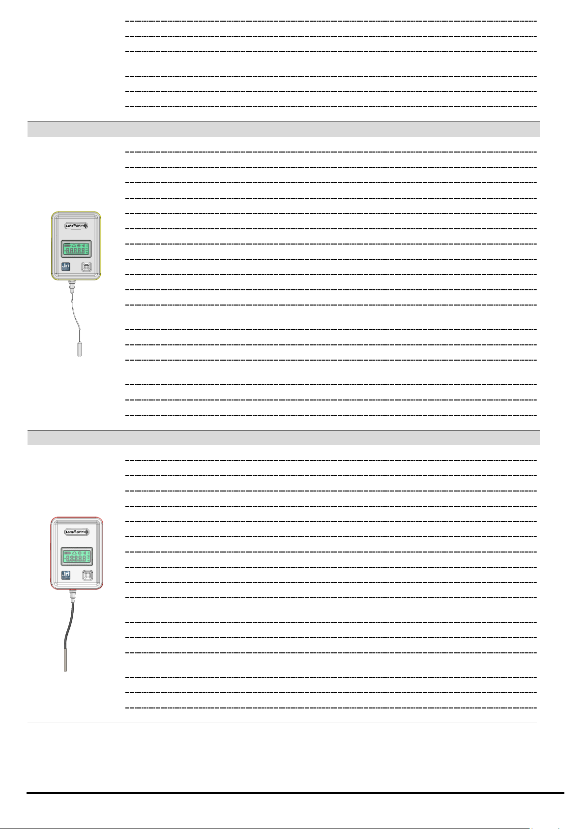
LoRa® SPY T2 – Standard remote temperature
HIM
: 1 RGB LED + 1 touch-sensitive button + 1 LCD display
Communication
: LoRa® 868MHz or 915MHz*
Memory
: 10 000 time-stamped measurements
Sensor
: PT100 external probe, non disconnectable, flat cable
Operating range
: from -30 to +70°C and 10 to 90%HR
Measurement range
: - 50 +105°C
Accuracy, standard version
: ±0.3°C from -20 to 30°C / ± 0.5°C outside this range
Accuracy, incubator version
: ±0.2°C de +30 à +50°C/± 0.5°C outside this range
IP rating
: IP 67
Cable length
: 30 cm, 3 m
PT100 probe resolution
: 0.01
Frequency of recording and
transmission
: adjustable from 1’ to 24h
Frequency of measurement
: 1 or 5min
Response time
: ~ 2 min. to 90% of the variation
Power source
: 3,6V Lithium battery– 2 to 4 years autonomy depending
on use
Case
: Polycarbonate – Food safe
Dimensions
: 87 mm x 64 mm x 25 mm
Weight
: ~ 100g (without probe)
LoRa® SPY T3 - Basse Température
HIM
: 1 RGB LED + 1 touch-sensitive button + 1 LCD display
Communication
: LoRa® 868MHz or 915MHz
Memory
: 10 000 time-stamped measurements
Sensor
: External PT100 non disconnectable Ø2,9mm
Operating range
: -20 to 50°C
Measurement range
: -200 to +0°C
Accuracy, standard version
: ±0.2°C from 0°C to -20°C and ±0.5°C outside this range
Accuracy, incubator version
: 0.01
IP rating
: IP 65
Cable length
: 50 cm and 3 m
Frequency of recording and
transmission
: adjustable from 5’ to 24h
Frequency of measurement
: 1 or 5min
Response time
: ~ 2 min. to 90% of the variation
Power source
: 3,6V Lithium battery– 2 to 4 years autonomy depending
on use
Case
: Polycarbonate – Food safe
Dimensions
: 87 mm x 64 mm x 25 mm
Weight
: ~ 100g (without probe)
©JRI 9
Page 10
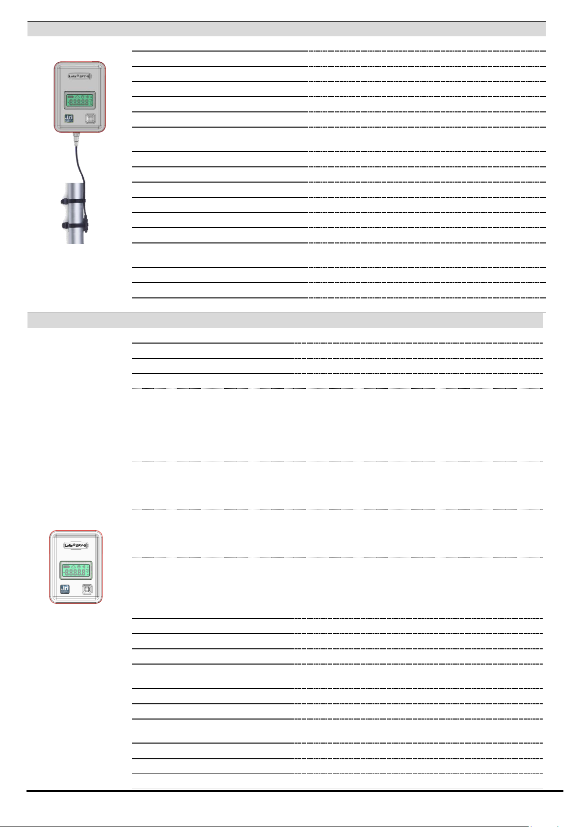
LoRa® SPY T4 Hygitherm (Calibrated for Hot Water Network)
A reflector to isolate the
sensor from ambient
conditions is available as
an option
HIM
: 1 RGB LED + 1 touch-sensitive button + 1 LCD display
Communication
: LoRa® 868MHz or 915MHz
Memory
: 10 000 time-stamped measurements
Sensor (with overmoulded support)
: PT100 non disconnectable
Operating range
: -30 to +70°C
Measurement range
: -40 to +85°C
Accuracy @55°C
: ±0.3°C on copper tube network
±0.5°C on HTA tube network
Resolution
: 0.01
IP rating
: IP 65
Cable length
: 2m
Frequency of recording and transmission
: from 1 min to 24h
Frequency of measurement
: 1 ou 5 min
Response time
: <2min. à 90% de la variation
Power source
: Lithium battery 3,6v – 2 to 4 years life duration
depending on use
Case
: Polycarbonate – food
Dimensions
: 87 mm x 63 mm x 25 mm
Weight
: ~ 100g (excluding probe and wire)
LoRa® SPY U - Universel
HIM
: 1 RGB LED + 1 touch-sensitive button + 1 LCD display
Communication
: LoRa® 868MHz or 915MHz*
Memory
: 10 000 time-stamped measurements
Input type :
PT100 input
measurement range:
resolution:
accuracy (not including
probe) :
-200°C to +300°C (*)
0,01°C
± 0,2°C from -20°C to +50°C
±0,3°C from -80°C to -20°C and from +50°C to +140°C
± 0,5°C beyond these ranges
Current input
measurement range:
resolution:
accuracy (control unit only):
0 to 20 mA or 4-20mA
0,001 mA
± 0,01 mA
Voltage input
measurement range:
resolution:
accuracy (control unit only)
0 à 1V
0,1 mV
±0.5 mV
On/Off or Count input
Type of input
measurement range:
resolution:
accuracy
Dry contact or 0-3,3V max
0 à 65535 – signal from 0 to 200Hz
1
±1
Operating range
: 0 to 50°C
Resolution
: 0.01
IP rating
: IP 34
Frequency of recording and
transmission
: adjustable from 1min to 24h
Frequency of measurement
: 1 or 5min in standard using MySirius)
Response time
: Depending of the probe used
Power source
: 3,6V Lithium battery– 2 to 4 years autonomy depending on
use
Case
: Polycarbonate – Food safe
Dimensions
: 87 mm x 64 mm x 25 mm
Weight
: ~ 100g (without probe)
©JRI 10
Page 11

*2018 4th trimestrial.
EN 12830
Yes for T0, T1 and T2 models: these devices must be verified
regularly according to EN 13486 (recommendation is once
per year)
CE ERM
EN 301 489 / EN 61000 / EN 61010 / EN 55022 / EN 300 220
a) Compliance
All our products are in compliance with the following standards:
VIII. MAINTENANCE
Clean the device with a soft cloth, either dry or slightly moistened with water. To remove stubborn dust,
use a cloth soaked in a diluted, non-abrasive detergent. Then wipe carefully with a soft dry cloth.
Never use benzene, thinner, alcohol or any type of solvent, which can cause discoloration or deformation
of the surfaces.
©JRI 11
Page 12
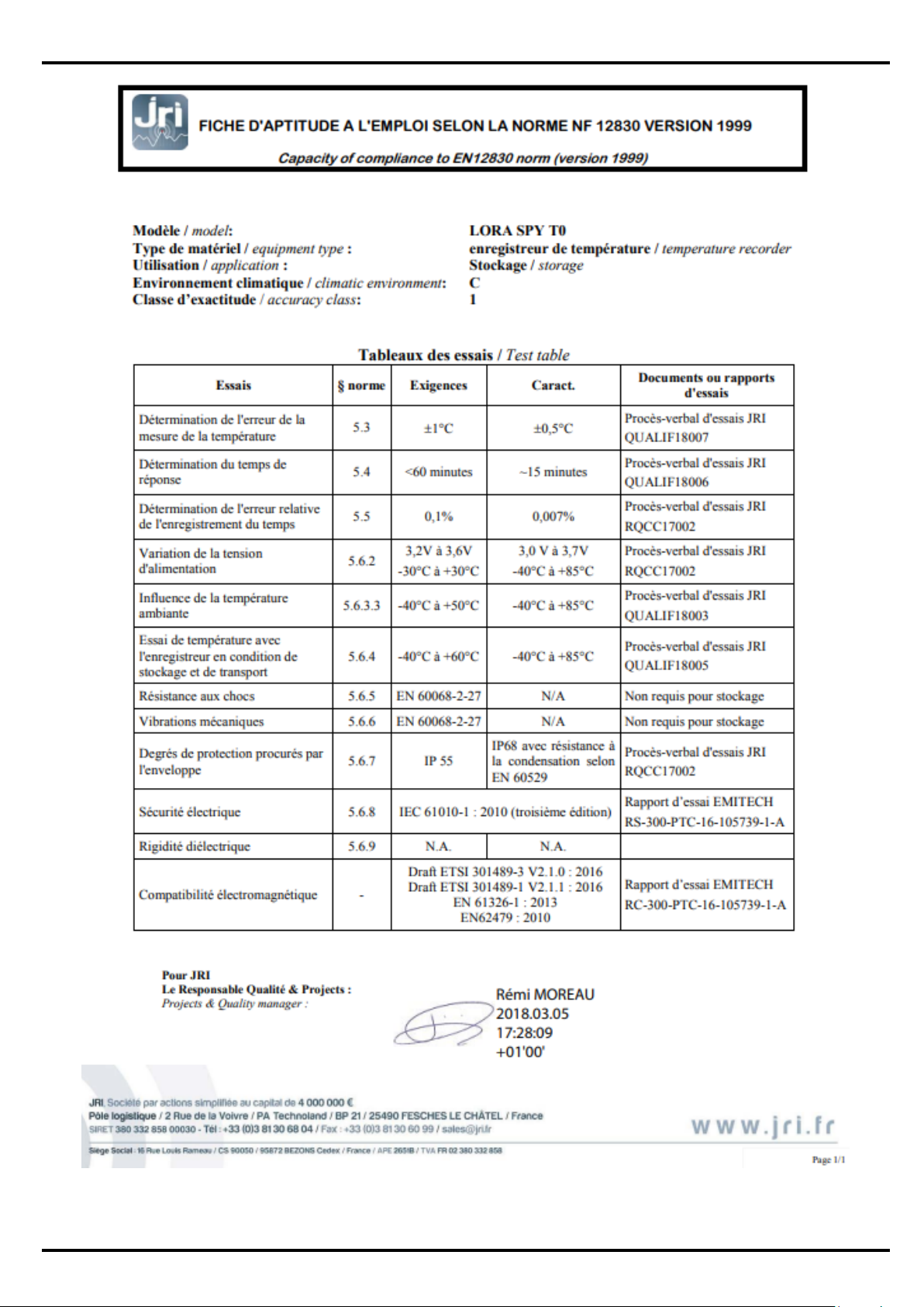
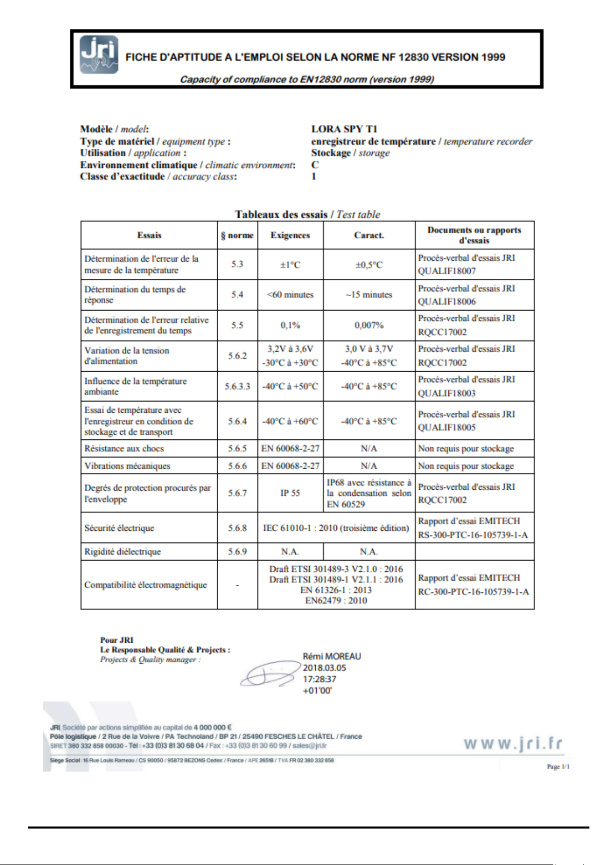
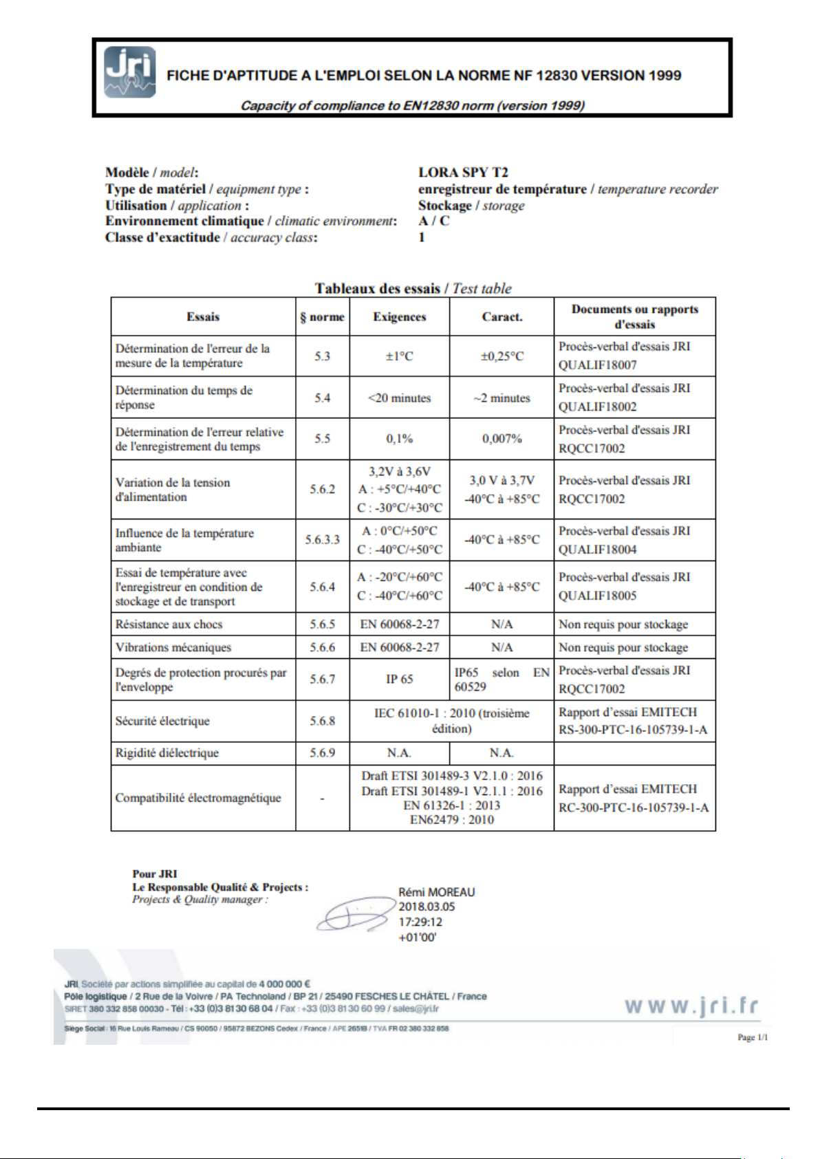
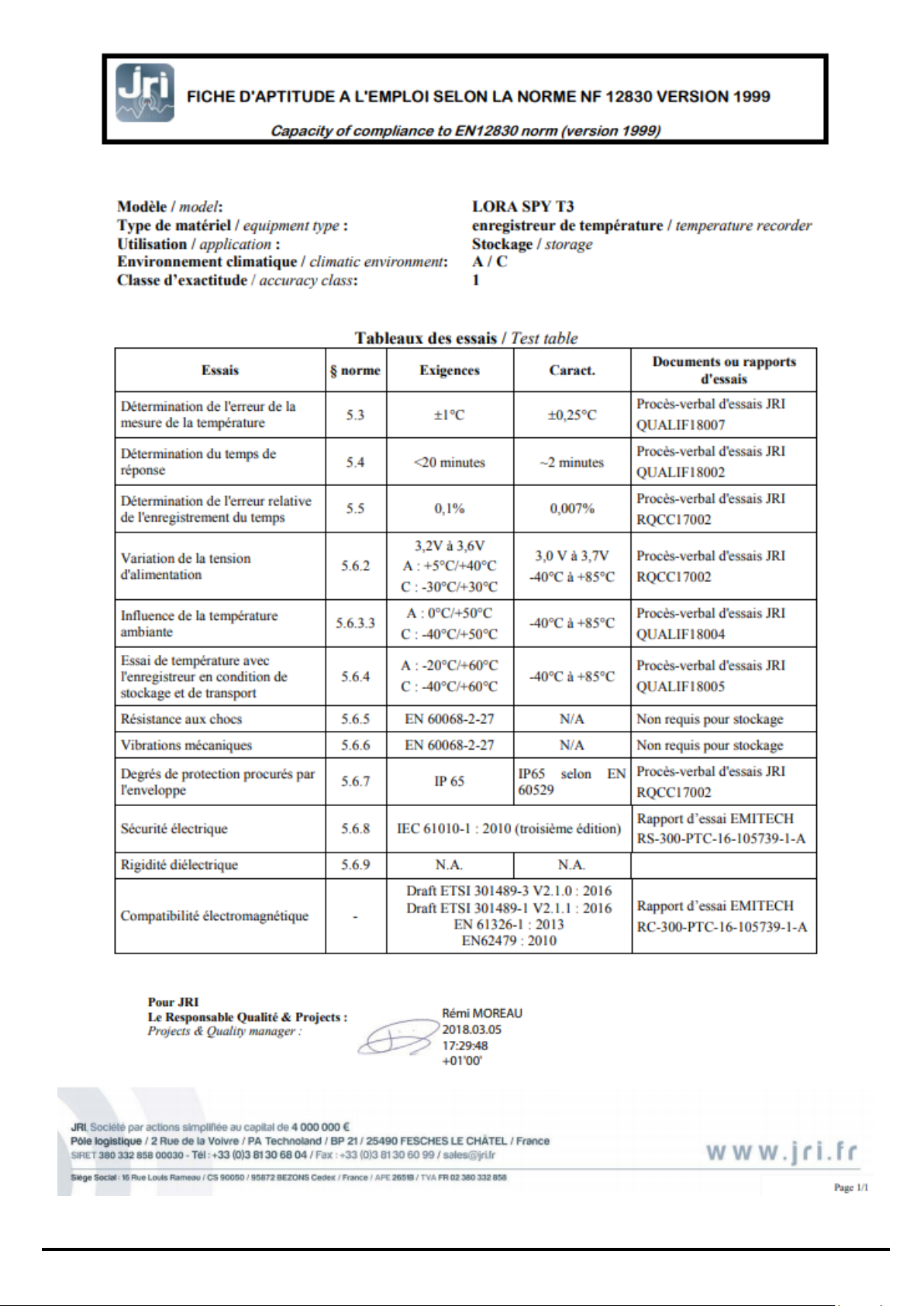
IX. SUITABILITIES FOR USE (LORA® SPY T0-T1-T2-T3)
©JRI 12
Page 13
©JRI 13
Page 14
©JRI 14
Page 15
©JRI 15
Page 16

X. GUARANTEE
Our material is guaranteed for one year, parts and labor, against any manufacturing defect, functional
failure or abnormal wear. This guarantee covers only the replacement of parts recognized to be defective
as well as the repair of the material in question returned shipping paid to our workshops, and excludes all
damages and interest or incidental expenses.
The starting point of the guarantee is the date of invoice of the concerned product. The invoice must be
provided for any request for application of the guarantee. Repairs under guarantee in no way extend the
guarantee period accorded to the product at the time of sale. Deterioration due to any abnormal usage or
to storage under adverse environmental conditions is excluded from our guarantee.
XI. MAINTENANCE CONTRACT
How best to optimize your radiofrequency installation?
Radiofrequency measurement systems communicate through Hertzian waves. Many factors (change in
installation, moving, supplemental wall, interference with another radio system…) can nonetheless modify
the radio pathway previously defined. The use of radiofrequency thus requires periodic monitoring by
recognized specialists.
It is for this reason that JRI has developed for you the maintenance contract. We simplify your procedures
by offering you a fully-integrated solution. This global service offer includes both maintenance and a
metrological service, ensuring the optimum functioning of your devices or of your installation.
You'll no longer have to worry about the maintenance of your devices!
This maintenance contract allows you to benefit, for a minimum period of 2 years, from a variety of
services such as:
- annual or biannual verification of the material
- an extension of the guarantee
- telemaintenance
- telephone assistance +33 (0) 892 680 933 (0,282 € HT/min)
- replacement of the material onsite or by a return to the factory
- verification of measurement accuracy (metrological certificate)
- battery replacement
- access to new software versions
- intervention within 48 working hours following identification of the fault by our experts
XII. ENVIRONMENTAL PROTECTION
JRI recommends to its customers the disposal of their unusable and/or irreparable measurement and
recording materials in a manner compatible with the protection of the environment. As the production of
waste materials cannot be avoided, these should be reused through the recycling process best adapted to
the considered materials and to the protection of the environment.
RoHS Directive
The RoHS European directive regulates and limits the presence of dangerous substances in
electronic and electric equipment (EEE).
All new electronic equipment designed, developed and manufactured by JRI are in compliance
with the aforementioned Directive 2002/95/CE.
©JRI 16
 Loading...