


MODEL 470 OPERATOR’S MANUAL
20195 South Diamond Lake Road, STE 100
Rogers, MN 55374
800.966.8442
www.jrcoinc.com
1
Operator’s Manual 7283-1.JRC | Rev.C.1
WARNING
READ AND UNDERSTAND THE OWNER’S MANUAL COMPLETELY BEFORE USING
THIS ATTACHMENT. ASSEMBLE, TEST AND USE ONLY IN ACCORDANCE WITH THE
OWNER’S MANUAL INSTRUCTIONS.

MODEL 470 OPERATOR’S MANUAL
20195 South Diamond Lake Road, STE 100
Rogers, MN 55374
800.966.8442
www.jrcoinc.com
2
Table of Contents
1 Introduction ................................................................................................................................................................ 3
1.1 ... Application ............................................................................................................................................................................3
1.2 ... Navigating This Manual ..................................................................................................................................................3
1.3 ... Operation References/Terminology ..........................................................................................................................4
1.4 ... Owner Assistance ................................................................................................................................................................4
1.5 ... Model Identification ..........................................................................................................................................................4
1.6 ... Further Assistance .............................................................................................................................................................5
2 Assembly and Set-up ............................................................................................................................................... 5
2.1 ... Packing List ...........................................................................................................................................................................5
2.2 ... Parts Breakdown ................................................................................................................................................................6
2.3 ... Tools Required .....................................................................................................................................................................7
2.4 ... Power Unit Requirements ...............................................................................................................................................7
2.5 ... Unpacking Your Attachment .........................................................................................................................................8
2.6 ... Torque Requirements .......................................................................................................................................................8
3 Assembly ...................................................................................................................................................................... 8
3.1 General Assembly ...................................................................................................................................................................8
3.2 ... Wheels to Yokes Assembly ..............................................................................................................................................8
3.3 ... Support Arm Attachment Assembly ...........................................................................................................................9
4 Mount Installation .................................................................................................................................................................. 10
4.1 Typical Floating Deck Mower ........................................................................................................................................ 10
4.2 Typical Fixed Deck Mower.............................................................................................................................................. 11
5 Install U-brackets and Attach to Mount ...................................................................................................................... 11
5.1 Assemble U-brackets and clamp plates as shown ................................................................................................. 11
5.2 Attach Dethatcher to Mount Bar................................................................................................................................. 12
6 Adjustments ............................................................................................................................................................................... 13
7 Operation Instructions ........................................................................................................................................ 13
7.1 Before Operation .................................................................................................................................................................. 13
7.2 Operator Safety .................................................................................................................................................................... 14
7.3 Operation ................................................................................................................................................................................. 14
8 Transporting ............................................................................................................................................................ 16
8.1 ... Raising Tine Rake Dethatcher ................................................................................................................................... 16

MODEL 470 OPERATOR’S MANUAL
20195 South Diamond Lake Road, STE 100
Rogers, MN 55374
800.966.8442
www.jrcoinc.com
3
9 Storage Instructions ......................................................................................................................................................... 17
9.1 Storing Your Tine Rake Dethatcher ............................................................................................................................ 17
10 Removing Rake ....................................................................................................................................................... 17
10.1 Removing Your Tine Rake Dethatcher .................................................................................................................... 17
10.2 Attaching Tine Rake Dethatcher ............................................................................................................................... 17
11 Field Use Set-up and Instructions ............................................................................................................................ 17
11.1 Field Preparation Tine Rake Dethatcher ............................................................................................................... 18
12 Specifications .................................................................................................................................................................... 18
13 Maintenance Instructions .................................................................................................................................. 18
13.1 General ................................................................................................................................................................................... 18
13.2 Replacing Tines .................................................................................................................................................................. 18
1 Introduction
JRCO takes pride in its attachments and have designed and engineered quality, commercial built attachments
designed to help you efficiently and effectively be more productive at tasks.
1.1 Application
JRCO front-mount dethatchers are available in 36, 46 or 60” widths for commercial walk-behind, zero turn
stand up mowers or riding mowers.
The Tine Rake Dethatcher is the ultimate spring clean-up tool. Use the rake for the first mowing of the spring to
remove thatch, embedded leaves and debris. The patented tines lift thatch without damaging healthy turfgrass
and at the same time comb matted grass giving the lawn a clean, hand-raked appearance.
After a hot summer, use Tine Rake Dethatcher to surface aerate the soil. This promotes root development and
makes room for thicker turfgrass. Use the dethatcher during seeding operations to rake in seed and accelerate
germination. Finally, use Tine Rake Dethatcher for the last mowing of the fall leaving a picture-perfect, clean
lawn.
Whether you mulch or bag, the Tine Rake Dethatcher can be used throughout the growing season as a tool to
control thatch accumulation and reduce the chance of turf disease.
The Tine Rake Dethatcher quickly attaches to the JRCO mount bar with clevis pins.
See the JRCO Mount Fit List or call JRCO or your JRCO dealer for the mount bar model that fits your mower!
1.2 Navigating This Manual
1. Use this manual to help familiarize yourself with safety, assembly, operation, adjustments,
troubleshooting, maintenance, specifications and warranty information. It is very important that you
read this manual and follow the instructions to ensure safe operation of the attachment.
2. Please visit www.jrcoinc.com for updated information.

MODEL 470 OPERATOR’S MANUAL
20195 South Diamond Lake Road, STE 100
Rogers, MN 55374
800.966.8442
www.jrcoinc.com
4
1.3 Operation References/Terminology
References throughout this manual referred to as “Right” or “Left” are determined by being seated face-
forward on Mower and facing the direction the unit will operate while in use.
1.4 Owner Assistance
Please complete the Warranty/Product Registration at the time of purchase. You will need to fill out and mail
warranty card or you may visit our website www.jrcoinc.com and complete our online registration form. We
require this information so we can keep you up to date with any important information about your attachment
and provide you with the best customer service possible.
The parts and components used on your JRCO Attachment have been specifically engineered for JRCO
Attachments and should only be replaced with JRCO parts. Contact your local JRCO Dealer for replacement
parts or contact our customer service department for assistance in parts, locating your local servicing dealer
and more. Your local dealer is equipped and trained to handle service and repair for your attachment.
1.5 Model Identification
Please fill in your model and serial number below for future reference. This will help assist in prompt service
when ordering parts and service for your local JRCO Dealer.
Model No.__________________________________ Serial No. ________________________________________
Refer to the image below for location of your serial number plate:

MODEL 470 OPERATOR’S MANUAL
20195 South Diamond Lake Road, STE 100
Rogers, MN 55374
800.966.8442
www.jrcoinc.com
5
1.6 Further Assistance
Your dealer and all of us at JRCO want you to be pleased with your attachment. Should you require further
assistance or have questions regarding your attachment, please contact your local dealer where you purchased
your attachment. If you are unable to satisfy your needs by your local dealer, please contact us at:
JRCO
20195 South Diamond Lake Road, STE 100
Rogers, MN 55374
800-966-8442
info@jrcoinc.com
www.jrcoinc.com
2 Assembly and Set-up
2.1 Packing List
1. Deck assembly 27 tines for 36”, 35 for 46”
and 47 for 60”
2. Support arm channel
3. Yoke/Wheel brace (left)
4. Yoke/Wheel brace (right)
5. Mount bar – varies by model
6. Wheel
7. Lower Lift Handle
8. Hardware bag – Rake Assembly
9. U-bracket bag
10. Hardware bag – Mounting Hardware -
Varies by model
11. Handle Topper – Varies by model
12. Latch Hoop – Varies by model
13. Latch Lift assembly

MODEL 470 OPERATOR’S MANUAL
20195 South Diamond Lake Road, STE 100
Rogers, MN 55374
800.966.8442
www.jrcoinc.com
6
2.2 Parts Breakdown

MODEL 470 OPERATOR’S MANUAL
20195 South Diamond Lake Road, STE 100
Rogers, MN 55374
800.966.8442
www.jrcoinc.com
7
Ref
Part No.
Description
Qty
Ref
Part No.
Description
Qty
1
4679.JRC
Wheel 1.75 x 8
2 19
4624DD.JRC
Tine Double-double loop 36”
27 4690.JRC
Wheel 3.0 x 8 Optional HD
2 Tine Double-double loop 46”
35 2 4683-2.JRC
5/8” Oilite flange bushing
4 Tine Double-double loop 60”
47 3 4661S.JRC
Shaft collar w/set screw
2 20
4674-7.JRC
24.5” Support arm channel,
2 4 4673.JRC
Yoke
2 21
4110.JRC
Circle Cotter
6 4673-1.JRC
Yoke – Optional HD wheel
2
22
4684.JRC
3/8-16 x 2 ¾” Clevis pin
4 6 7282.JRC
½-13 x 3” Hex bolt
2 25
4680.JRC
Grip
1 7411.JRC
1/2-13 x 4 ½” Hex bolt – HD
2 28
7250.JRC
3/8-16 Serrated flange nut
4 7 4233.JRC
1/3-13 Two-way locknut
2 29
4668.JRC
U-bracket
2 8 7247.JRC
5/16-18 Serrated flange nut
16 30
4631-2.JRC
Clamp plate
2 9 (7389L).JRC
Left wheel brace assembly
1 31
7277.JRC
3/8-16 x 1 Carriage bolt
4
10
(7389R).JRC
Right wheel brace assembly
1 33
4670-9.JRC
Mount bar 39”
1
11
4617.JRC
46” Deck – 35 Tine
1
4670-10.JRC
Mount bar 44”
1
4617-1.JRC
60” deck – 47 Tine
1
4670-11.JRC
Mount bar 54”
1 4617-2.JRC
36” Deck -27 Tine
1 34
4671-1.JRC
Clamp bar 3.0”
1
13
7232.JRC
5/16-18 x ¾” Serrated flange
16
4671-2.JRC
Clamp bar 4.4”
1
14
7251.JRC
1/8 x 1 ½” Cotter pin
4
4671-3.JRC
Clamp bar 3.3”
1
15
4638-1.JRC
7/8” Machine bushing
4
4671-4.JRC
Clamp bar 3.8”
1
16
4623.JRC
46” Tine rod
2
4671-5.JRC
Clamp bar 5.1
1 4623-1.JRC
60” Tine rod
2 47
8317-1.JRC
Latch Hoop, Wide Spacing
1 4623-2.JRC
36” Tine rod
2
8317-2.JRC
Latch Hoop, Narrow Spacing
1
17
4622.JRC
46” Tine tube
2 50
8329.JRC
Handle, Lower
1
4622-1.JRC
60” Tine tube
2 51A
(8353).JRC
Handle Topper Assembly w/grip 1
1 4622-2.JRC
36” Tine tube
2 51B
(8355).JRC
Handle Topper Assembly w/grip 2
1
18
4621.JRC
46” Stabilizer tube
2 51C
(8357).JRC
Handle Topper Assembly w/grip 2
1 4621-1.JRC
60” Stabilizer tube
2 54
8337.JRC
Latch Lift Assembly
1 4621-2.JRC
36” Stabilizer tube
2 55
8339.JRC
Clevis Pin, 3/8 x 3”
2 56
8341.JRC
Hitch Pin, ¼ x 1”
1 60
8338.JRC
Carriage bolt, 5/16-18 x ¾”
2
2.3 Tools Required
Socket Wrench: ½”, 9/16” & ¾”
Open or Box End Wrench: ½”, 9/16” & ¾”
Allen Wrench: 5/32”
Drill: with 7/16” bit (for typical mount install)
2.4 Power Unit Requirements
The Tine Rake Dethatcher is designed to be attached to a JRCO Mount Bar for mounting on walk-behind
mowers, stand-up mowers, zero turn mowers, and lawn tractors.

MODEL 470 OPERATOR’S MANUAL
20195 South Diamond Lake Road, STE 100
Rogers, MN 55374
800.966.8442
www.jrcoinc.com
8
Figure 1-1
2.5 Unpacking Your Attachment
CAUTION
SHARP EDGES.
Sharp tines, eye poke hazard
Wear safety Glasses
Your Tine Rake Dethatcher will ship in 1 box. Carefully set the box on a flat working area. Carefully unbox the
attachment and verify that all fasteners and components are included. (see packaging list on page 5)
2.6 Torque Requirements
Please reference the Torque Chart below for correct values when assembling your attachment.
5/16”
Serrated Flange Nut/Bolt
20 ft lb
3/8”
HH Capscrew 3/8-16 x 3”
30 ft lb
3 Assembly
3.1 General Assembly
This attachment is shipped partially assembled. If purchased from a JRCO Dealer, the dealership may assist in
assembly of attachment. Review all safety and assembly instructions in this manual before assembly.
3.2 Wheels to Yokes Assembly
Refer to Figure 1-1
1. Position the rake as shown. The front of
the rake is identified by a three-hole
pattern in the center.
2. Fasten the left and right wheel braces to
the rakes, using four 5/16 x ¾ serrated
flange bolts and nuts per side, as shown.
3. Attach the wheels to the yokes.
4. Place the wheel in the yoke, and secure
with a ½ x 3” (1/2 x 4 ½” for heavyduty wheels) hex head bolt and 2-way locknut.
IMPORTANT: Do not over tighten. Leave enough space for wheels to spin in yokes.

MODEL 470 OPERATOR’S MANUAL
20195 South Diamond Lake Road, STE 100
Rogers, MN 55374
800.966.8442
www.jrcoinc.com
9
3.3 Support Arm Attachment Assembly
Refer to Figure 1-2
1. Install the support arm channels onto the deck in the
appropriate holes.
2. The inner set of holes is used for mount bars with 10-
inch vertical channel spacing (all current mount bars)
and the outer set of holes is used for bars with 15-inch
vertical channel spacing (some older mount bars).
3. Secure with eight 5/16” x ¾” serrated flange bolts and
serrated nuts.
4. The latch lift assembly may be attached to either the
left or right support arm. Orient the latch lift assembly
as shown in Figure 1-2.
5. Secure latch lift assembly to support arm channel using
two 5/16 x ¾” carriage bolts and serrated nuts.
Figure 1-2

MODEL 470 OPERATOR’S MANUAL
20195 South Diamond Lake Road, STE 100
Rogers, MN 55374
800.966.8442
www.jrcoinc.com
10
4 Mount Installation
Many models have specific hardware and mount instructions. These mount instructions are packaged in the
mount hardware bag. If there are no specific mount instructions, one of these universal methods should apply.
4.1 Typical Floating Deck Mower
Mount bar will be installed UNDER the caster arm of most mid-mount ZTRs. The top of the mount bar should
be 14 – 16 inches off the ground. If it will be lower than 13 inches, install bar on the top of the caster arms.
Temporarily clamp the mount bar in position as shown. Swivel front wheels fully to ensure clearance with the
vertical channels of the mount bar. It may be necessary to slightly off-set the bar to ensure clearance at the left
wheel. Mark the position of the caster arms onto the mount bar with a felt tip pen.
Remove the mount bar and position a clamp bar over the marks. Mark the location of the and drill 7/16” holes
through the bar.
Install the bar using four hex head bolts, clamp bars and locknuts. Install the bolts with the heads at the bottom
to clear the caster yokes.

MODEL 470 OPERATOR’S MANUAL
20195 South Diamond Lake Road, STE 100
Rogers, MN 55374
800.966.8442
www.jrcoinc.com
11
4.2 Typical Fixed Deck Mower
Loosely bolt the left and right mounting plates to each caster support arm using four 3/8 x 2 1/2" hex bolts,
eight flat washers, and four nylon locknuts. Lay the mount bar across the top of the mounting plates, and
loosely attach the bar with two 3.0" clamp bars, and four 3/8 x 2 1/2" hex bolts and nylon locknuts. Install the
bolts with the heads down and nuts on top.
Slide the u-brackets onto the mount bar. Position the mount plates so there is clearance for the wheels to fully
caster and the bar is level. Be sure the wheels will not contact the attachment or the vertical channels on the
mount bar. Tighten all fasteners.
5 Install U-brackets and Attach to Mount
5.1 Assemble U-brackets and clamp plates as shown
NOTE hole orientation
1. Assemble u-bracket and clamp plate with 3/8-16 x 1 carriage bolts
and serrated flange nuts.
2. Slide u-bracket assemblies onto mount bar and set initial height
about 9 ½” from ground.

MODEL 470 OPERATOR’S MANUAL
20195 South Diamond Lake Road, STE 100
Rogers, MN 55374
800.966.8442
www.jrcoinc.com
12
5.2 Attach Dethatcher to Mount Bar
1. Attach the rake to the u-brackets (Position A) using two 3/8 x 2 3/4“ clevis pins inserted through
the bottom u-bracket hole and the support arm channel. Secure with circle cotters.
2. Place the latch hoop over the u-brackets (Position B) and secure with two 3/8 x 3” clevis pins and
circle cotters.
3. Install the lower lift handle at position C & D using two 3/8 x 2 ¾” clevis pins and circle cotters.
4. Place the handle topper over the lower lift handle and secure with a ¼ x 1” hitch pin.
Figure 1-7
Figure 1-7
Figure 1-8

MODEL 470 OPERATOR’S MANUAL
20195 South Diamond Lake Road, STE 100
Rogers, MN 55374
800.966.8442
www.jrcoinc.com
13
6 Adjustments
Refer to Figure 1-9
1. Adjust the height of the dethatcher with the rake
on level, paved ground. Adjust the u-brackets
until the bottom of the support arm channels are
9 ½” above the ground. It may be necessary to
remove the lift handle to gain access to the
adjustment.
2. Level the dethatcher by adjusting the shaft collars
on each caster assembly. The top of the rake decks
should be 9 ½” from the ground.
3. When adjusted properly, the tips of the tines should
be approximately ¾” from a hard surfaced ground.
When the dethatcher is on turf, the tines will
engage the grass and work back and forth lifting
and flicking dead grass and thatch.
Figure 1-9
7 Operation Instructions
7.1 Before Operation
Safety, hazard and accident prevention is essential. You must use awareness, concern, and proper training
when operating and utilizing this attachment. You must NOT use this attachment without reading and
understanding the Operator’s Manual. Make sure the operator has completed and understands the contents of
this manual before operation. Refer to the chart on the next page for key areas and ensure they are
understood:
• Hills
• Obstacles
• Children

MODEL 470 OPERATOR’S MANUAL
20195 South Diamond Lake Road, STE 100
Rogers, MN 55374
800.966.8442
www.jrcoinc.com
14
7.2 Operator Safety
7.3 Operation
1. Lift the rake to the latch position by pulling back (riding
mowers) or pushing down (walk-behind mowers) on the
lift handle to raise the rake until the latch hoop engages
the hooks. The rake will latch with the front wheels
approximately 12” off the ground. Refer to Figure 1-10.
Figure 1-10
CAUTION
• Know the dethatcher’s controls and how to stop quickly. READ THE
OWNER’S MANUAL.
• Shut off the engine before attaching, adjusting or disconnecting the Tine
Rake Dethatcher.
• Reduce speed on uneven ground.
• DO NOT allow dethatcher to strike hard surfaces: curbs, fences,
driveways, sidewalks, etc.
• DO NOT ride or stand on rake.
• Keep all bolts and nuts tightened.
• DO NOT allow others, including children and pets, in the area while
operating the Tine Rake Dethatcher
• STOP the mower when releasing the latch to lower the dethatcher for
raking or when raising the dethatcher for transporting.
• For added Tine Rake Dethatcher stability and to prevent loss of control
when using Tine Rake Dethatcher: Rake up and down the face of slopes
– never across the face of any slope. Do drive at reduced speeds on
uneven ground and when turning corners.

MODEL 470 OPERATOR’S MANUAL
20195 South Diamond Lake Road, STE 100
Rogers, MN 55374
800.966.8442
www.jrcoinc.com
15
2. To lower the dethatcher, pull or push down the lift handle,
slightly lifting the dethatcher, until the latch lift pawl clicks into
the un-latch position. Slowly lower the rake to the ground. Refer
to Figure 1-11 and 1-12
3. Do no leave the rake in the latched position when trailering the
mower and dethatcher. Raise the dethatcher to the “trailering
position or lower the weight to the trailer floor. Failure to do so
may put excessive stress on the latch components. Refer to Figure
1-15 in the next section.
2
CAUTION
• Use the Tine Rake Dethatcher for its intended purposes only. Never use
it to carry, push, pull or drag any object other than its intended purpose.
• Misuse can lead to damage of the attachment.
• Do not exceed speeds of 8 mph.
• Mark all sprinkler heads and other obstacles in lawn.
• A Crush Hazard exists when mounting attachment to mount bar. Do Not
allow anyone to stand between tractor and attachment while mounting.
• Always make sure the clevis pins are secure before operation.
• Always make sure the parking brake is engaged on mower/UTV, engine
is turned OFF and key is removed before mounting the attachment.
Figure 1-11
Figure 1-12
MODEL 470 OPERATOR’S MANUAL
20195 South Diamond Lake Road, STE 100
Rogers, MN 55374
800.966.8442
www.jrcoinc.com
16
8 Transporting
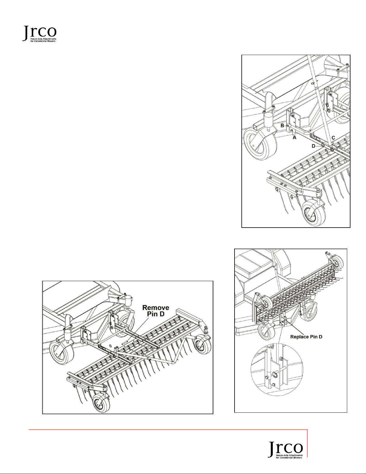
8.1 Raising Tine Rake Dethatcher
Refer to Figures 1-13, 1-14, and 1-15
1. Remove clevis pin in the lift handle (Position D)
2. Fold the lift handle forward. Lift the rake by hand to the
verticle position.
3. Lift the rake to the trailer position
4. Replace the clevis pin through the u-bracket and in
front of the support arm channel. Secure with circle
cotter.
CAUTION: Wear eye protection and use care especially when the
dethatcher is in the vertical position. Sharp tines can cause injury.
5. Secure rake to trailer, using ratchet straps, when transporting.
Trailer Tine Rake Dethatcher only in the Full Up or Full Down
Position
Figure 1-13
Figure 1-14 Figure 1-15

MODEL 470 OPERATOR’S MANUAL
20195 South Diamond Lake Road, STE 100
Rogers, MN 55374
800.966.8442
www.jrcoinc.com
17
9 Storage Instructions
9.1 Storing Your Tine Rake Dethatcher
Clean, inspect, service and repair any parts that are necessary. This will ensure the attachment is ready for use
the next time it’s in the field and ensure repairs are not accidentally forgotten or overlooked.
1. Repaint parts where paint is worn or chipped to prevent rust from forming.
2. Replaced all damaged or missing decals.
3. Store Tine Rake Dethatcher indoors if possible. Inside storage will reduce maintenance and extend life
of attachment. Store upright or upside down
4. Inspect for loose or worn parts and adjust or replace as needed.
5. Check for missing bolts and/or nuts and replace if necessary. Inspect for any loose bolts and tighten as
needed.
6. Do not store with weight on tines.
10 Removing Rake
10.1 Removing Your Tine Rake Dethatcher
1. Remove clevis pins from support arm channel.
2. Carefully remove dethatcher from mount bar.
3. Remove latch hoop and store with dethatcher,
10.2 Attaching Tine Rake Dethatcher
1. Park mower close to clevis area.
2. Attach Tine Rake Dethatcher securely with clevis pins.
11 Field Use Set-up and Instructions
• The following procedures should be carried out by the operator. Other persons should be cleared of
the area.
CAUTION
• A pinch point exists when mounting attachment to mount bar. Do Not
allow anyone to stand between tractor and attachment while mounting.
• Always make sure the parking brake is engaged on mower. Turn engine
OFF and key is removed before mounting the attachment.

MODEL 470 OPERATOR’S MANUAL
20195 South Diamond Lake Road, STE 100
Rogers, MN 55374
800.966.8442
www.jrcoinc.com
18
11.1 Field Preparation Tine Rake Dethatcher
1. Ensure your Tine Rake Dethatcher is approximately 9 ½” inches above solid ground.
2. Tine should not be touching or scraping the hard surface.
3. Tines will engage grass when on turf surface
12 Specifications
36in
46in
60in
Shipping Weight
78lbs
86lbs
100lbs
Width
36.5”
46.5”
61.5”
Length
36”
36”
36”
Height
14”
14”
14”
Amount of Tines
27
35
47
13 Maintenance Instructions
13.1 General
Proper servicing and adjustment is key to extending the life of your attachment. Carefully inspect and
routinely maintain to avoid costly downtime and repairs.
Check all bolts and nuts after using for several hours to ensure they are secure. Replace any worn, damaged or
missing safety labels.
The parts on your JRCO Tine Rake Dethatcher have been designed specifically for your attachment and should
be replaced with genuine parts from your local
JRCO Dealer. Do not alter the equipment in any
way.
13.2 Replacing Tines
1. Disconnect the rake from the mower, and
place upside down. Remove either wheel
brace assembly.
2. Remove the cotter pin and machine bushing
from the opposite end of the rake that the
wheel brace was removed. Slide the
stabilizer tube (7/8” diameter) out of the
bottom loops of the tines.
3. Lift up slightly and slide out the tine rod and
tine tube from the top tine loop.
Figure 1-16

MODEL 470 OPERATOR’S MANUAL
20195 South Diamond Lake Road, STE 100
Rogers, MN 55374
800.966.8442
www.jrcoinc.com
19
4. Remove and replace tines as necessary.
Slide the tine forward in the deck, until the
loop disengages the slot, lift upward and
pull it back, out of the hole.
5. Replace tines by inserting the end into the
round hole, slide forward until the loop
can go past the deck flange. Push it down
and back into the slot.
6. Insert the tine rod in the back of the top
loop. Insert the tine tube in the front of the
top loop. Be sure they pass through each
tine.
7. Replace the stabilizer tube in the bottom
tine loop and secure with machine
bushing and a new cotter pin. Figure 1-17
8. Replace wheel brace.

For products purchased on or after January 1, 2018
20195 South Diamond Lake Road, Suite 100 • Rogers, MN 55374
Toll-Free: 800-966-8442 • Website: jrcoinc.com • Email: info@jrcoinc.com
Dear Valued Customer:
The Jrco Attachment you just purchased is built with the finest material and craftsmanship. Use this attachment properly and enjoy
the benefits from its high performance. By purchasing a Jrco Attachment, you show a desire for quality and durability. Like all
mechanical equipment this unit requires a due amount of care. Treat this unit like the high-quality piece of machinery it is. Neglect
and improper handling may impair its performance and is not covered by this limited warranty.
Thoroughly read the instructions and understand the operation before using your product. Always contact Jrco Product Support at 1800-966-8442 prior to having any service or warranty work performed, as some services performed by parties other than Jrco
approved service centers may void this warranty. This limited parts warranty is in lieu of any other warranty expressed or implied,
written or oral and Jrco assumes no other responsibility or liability outside that expressed within this limited warranty.
Limited Parts Warranty for Jrco Attachment:
Consumer Parts Warranty Period
Commercial Parts Warranty Period
Weldments
1 year from date of purchase by user
1 year from date of purchase by user
Electric Motor, Pump & Speed Controller
90 days from date of purchase by user
90 days from date of purchase by user
Wear Parts
Jrco shall not warrant normal wear items. High impact wear related components such as, but not limited to standard retention
hardware for wear items, tines and tine assemblies, seals, seal shields, grease fitting, bearings, bushings tires and wheel
assemblies. Routine maintenance items such as lubricants, adjustments, tune ups, and damage from operation with loose
hardware are not covered under limited warranty.
Engines
The engine warranty is covered under the terms and conditions as outlined by the engine manufactures warranty contained
herein and is the sole responsibility of the engine manufacturer. Normal engine maintenance such as spark plugs, oil changes, air
filters, adjustments, fuel system cleaning and obstruction due to build up is not covered by this Jrco limited warranty.
“Consumer use” means personal residential household use by a consumer. “Commercial use” means all other uses, including, but
not limited to, use for commercial, income producing or rental purposes or when purchased by a business.
This limited parts warranty applies to the original purchaser of the equipment (verification of purchase, in the form of a receipt, is the
responsibility of the buyer), is non-transferable, and covers parts. Parts will be replaced at no charge, except when the equipment has
failed due to lack of proper maintenance. If a part is no longer available, the part may be replaced with a similar part of equal function.
Any misuse, abuse, alteration or improper installation or operations will void warranty. Determining whether a part is to be replaced
or repaired is the sole decision of Jrco. Jrco will not provide for replacement of complete products due to defective parts. Any labor
costs incurred due to replacement or repair of items is the responsibility of the buyer and not covered under warranty. Transportation
costs to and from service center and/or service calls are the responsibility of the customer.
This limited warranty specifically excludes the following; failure of parts due to damage caused by accident, fire, flood, windstorm,
acts of God, applications not approved by Jrco in writing, corrosion caused by chemicals, use of replacement parts which do not
conform to manufacturer’s specifications, damage related to rodent and/or insect infestation and damage caused by vandalism.
Additional exclusions: loss of running time, inconvenience, loss of income, or loss of use, including any implied warranty of
merchantability of fitness for a specific use. Also, outdoor power equipment needs periodic parts and service to perform well, and this
limited warranty does not cover instances when normal use has exhausted the life of a component or the engine.
This limited warranty does not cover any personal injury or damage to surrounding property caused by failure of any part, misuse or
inability to use the product. Alteration of the product, including safety features, shall void this limited warranty

For products purchased on or after January 1, 2018
20195 South Diamond Lake Road, Suite 100 • Rogers, MN 55374
Toll-Free: 800-966-8442 • Website: jrcoinc.com • Email: info@jrcoinc.com

For products purchased on or after January 1, 2018
20195 South Diamond Lake Road, Suite 100 • Rogers, MN 55374
Toll-Free: 800-966-8442 • Website: jrcoinc.com • Email: info@jrcoinc.com
20195 S. Diamond Lake Road
Suite 100
Rogers, MN 55374
800-966-8442
 Loading...