

JRC NJU9214FG1 Datasheet
4•3/4 DIGIT SINGLE CHIP DIGITAL MULTIMETER LSI
!!
!GENERAL DESCRIPTION
!!
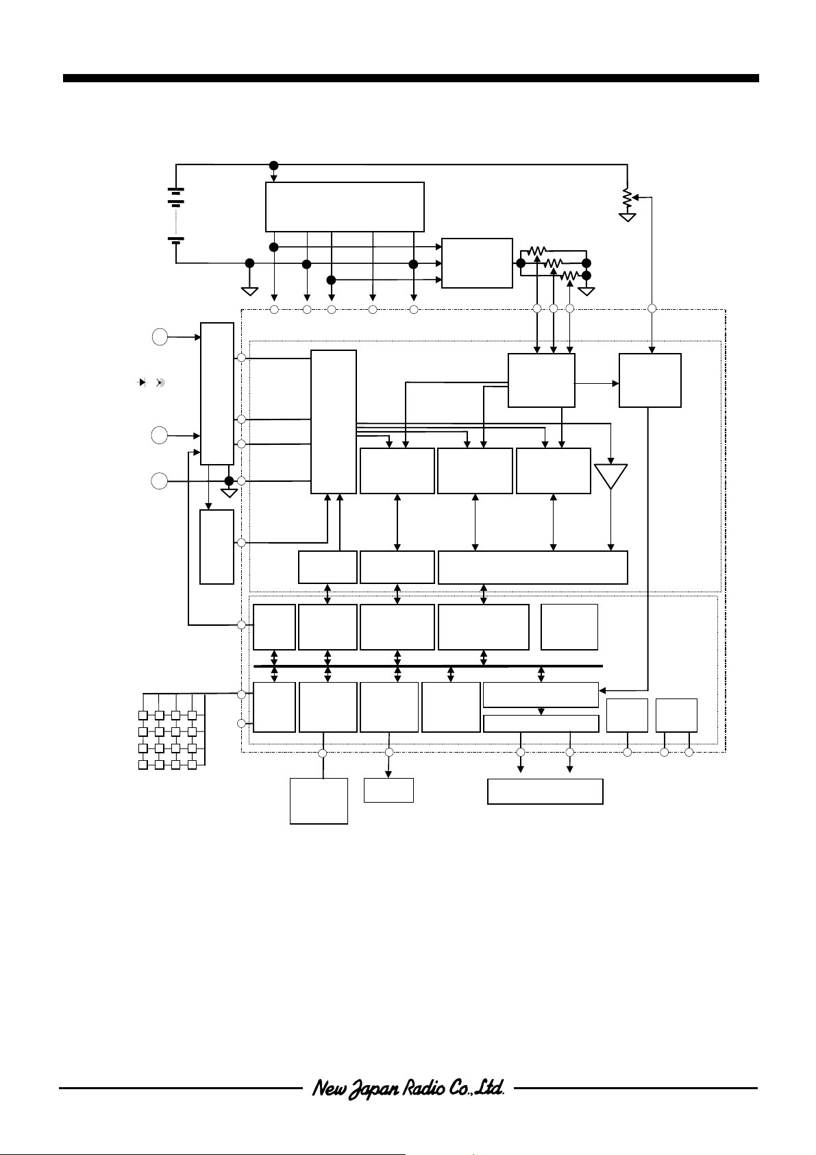
The NJU9214 is a 4•3/4 digits single chip digital multimeter LSI with
42 segments bargraph display .
The NJU9214 realizes high precision of ±40,000 counts measurement by the NJRC original dual-slope A to D converter and realizes
also quick response bargragh display and auto-ranging by another high
speed dual-slope A to D converter.
The input attenuator part is simplified because the resistor for resistance measurement is applied for voltage bleeder resistor.
Furthermore, the NJU9214 realizes root-mean-square measurement
for AC voltage and current by connecting a External RMS-DC Converter, and Data output by the on chip RS-232C interface circuit.
The NJU9214 is suitable for high precision and high performance
multimeter.
NJU9214
PRELIMINARY
PACKAGE OUTLINE
NJU9214FG1
!!
!FEATURES
!!
• 4•3/4 Digit Display (Available for UP to ±39,999 Display)
• 42 Segments Quick Response Bargraph Display
• NJRC Original Dual-Slope A to D Converter (±40,000Counts)
• High Speed Dual-Slope A to D Converter (±400Counts)
• Quick Response Auto-Ranging (20times/sec)
• Frequency/Capacitance/T achometer/Adapter Measurement
• Root-Mean-Square Measurement by connecting a External RMS-DC Converter
• External Relay Driving
• Data Memory/Data Hold/Relative Display/MAX, MIN Display
• Power-on Initializing
• Auto Power-off
• Buttery Life Detector
• Rotary/Push SW Mode Selection
• 1/4 Duty LCD Display Driver
• Piezo Buzzer Direct Driving
• RS-232C Interface
• External Reference Input required
• Low Operating Current
• C-MOS Technology
• Package Outline TQFP100
!!
AAAA
!BLOCK DIAGRAM
!!
DCV
DCV,
, ACV
ACV,,,,
DCVDCV
, ,
ACVACV
ΩΩΩΩ, , ,
, , ,CAP
CAP,,,,
, , ,, , ,
, ACmA
ACmA,,,,
, ,
ACmAACmA
, rpm
rpm
, ,
rpmrpm
COM
COM
COMCOM
CAPCAP
EXTERNAL
EXTERNALEXTERNAL
EXTERNAL
DCmA
DCmA,
DCmADCmA
FRQ
FRQ,
FRQFR Q
REGURATOR
REGURATOR
REGURATORREGURATOR
VDDA
VDDA AGND
AGND VSSA
VDDAVDDA
AGND AGND
+5.0V 0V
+5.0V 0V -5.0V 5.0V
+5.0V 0V +5.0V 0V
IVSL
IVSL,
, IVSH
IVSH
IVSLIVSL
, ,
VI,,,,
VIVI
VR2 to
to 7777,,,,
VR2VR2
to to
OVH,,,,
OVHOVH
OVX
OVXOVX
ADP
ADP
ADPADP
SGND
SGND
SGNDSGND
IVSHIVSH
VI
VR2
OVH
OVX
RESISTORS and S WITCHS
RESISTORS and S WITCHS RESISTORS and S WITCHS
RESISTORS and S WITCHS
VSSA
VDDD
VDDD VSSD
VSSAVSSA
SWITCH
SWITCHSWITCH
SWITCH
NETWORK
NETWORKNETWORK
NETWORK
VDDD VDDD
HIGH
HIGH
HIGHHIGH
SPEED
SPEED
SPEEDSPEED
A/D SECTION
A/D SECTION
A/D SECTIONA/D SECTION
-5.0V 5.0V
-5.0V 5.0V-5.0V 5.0V
VSSD
VSSDVSSD
0V
0V
0V 0V
REFERENCE
REFERENCE
REFERENCEREFERENCE
HIGH
HIGH
HIGHHIGH
RESOLUTION
RESOLUTION
RESOLUTIONRESOLUTION
A/D SECTION
A/D SECTION
A/D SECTIONA/D SECTION
VREF1
VREF2
VREF1VREF1
VREF1
VREF2VREF2
VREF2
REFERENCE
REFERENCE
REFERENCEREFERENCE
BUFFER
BUFFER
BUFFERBUFFER
CAPACITOR
CAPACITOR
CAPACITORCAPACITOR
A/D SECTION
A/D SECTION
A/D SECTIONA/D SECTION
VREF3
VREF3VREF3
VREF3
NJU9214
BATT
BATT
BATTBATT
LOW
LOW
LOWLOW
DETECTOR
DETECTOR
DETECTORDETECTOR
ANALOG
SECTION
FRQ
FRQ
FRQFRQ
BUFFER
BUFFER
BUFFERBUFFER
FC1
FC1 to
FC1FC1
KI1
KI1 to
KI1KI1
KEY MATRIX
KEY MATRIX
KEY MATRIXKEY MATRIX
RMS-DC
RMS-DCRMS-DC
RMS-DC
RD1
RD1 to
to 4444
RD1RD1
to to
to 4444,,,,
to to
to 5555
to to
TRX
TRX
TRXTRX
TXS
TXS
TXSTXS
RST
RST
RSTRST
PON
PON
PONPON
RMSIN
RMSIN
RMSINRMSIN
HIGH SPEED
I/F
I/F
I/F I/F
HIGH SPEED
HIGH SPEED
HIGH SPEEDHIGH SPEED
A/D CONTROLER
A/D CONTROLER
A/D CONTROLERA/D CONTROLER
HIGH SPEED
HIGH SPEEDHIGH SPEED
A/D I/F
A/D I/F
A/D I/FA/D I/F
BUZZER
BUZZER
BUZZERBUZZER
R
CONTROLE
CONTROLE
CONTROLECONTROLE
BZ
BZ
BUZZER
BUZZER
BUZZERBUZZER
HIGH RESOLUTION A/D I/F
HIGH RESOLUTION A/D I/F
HIGH RESOLUTION A/D I/FHIGH RESOLUTION A/D I/F
HIGH RESOLUTION
HIGH RESOLUTION
HIGH RESOLUTIONHIGH RESOLUTION
A/D CONTROLER
A/D CONTROLER
A/D CONTROLERA/D CONTROLER
CONTROLER
CONTROLER
4bit CPU
4bit CPU
4bit CPU4bit CPU
CONTROLERCONTROLER
LCD DRIVER and
LCD DRIVER and
LCD DRIVER andLCD DRIVER and
COM1
COM1 to 4
to 4 SEG1
COM1COM1
to 4 to 4
LCD
LCD
LCDLCD
SEG1 to
to 28
SEG1SEG1
to to
LCD
LCD
LCDLCD
POWER ON
POWER ON
POWER ONPO WER ON
INITIALIZE
INITIALIZE
INITIALIZEINITIALIZE
4bitBUS
4bitBUS
4bitBUS4bitBUS
POWER
POWER
POWER POWER
28
2828
TEST
TEST
TESTTEST
T1
T1 to
to T3
T1T1
to to
T3
T3T3
DIGITA L
SECTION
OSC
OSC
OSCOSC
XT1 XT2
XT1 XT2
XT1 XT2XT1 XT2
SWITCH
SWITCH
SWITCHSWITCH
NETWORK
NETWORK
RELAY
RELAY
RELAYRELAY
CONT-
CONT-
CONT-CONTROLER
ROLER
ROLERROLER
KEY
KEY
KEYKEY
NETWORKNETWORK
SWITCH
SWITCH
SWITCHSWITCH
NETWORK
NETWORK
NETWORKNETWORK
CONTROLER
CONTROLER
CONTROLERCONTROLER
RS232C
RS232C
RS232CRS232C
CONTROLER
CONTROLER
CONTROLERCONTROLER
TXD
DTR
TXDTXD
TXD
DTRDTR
DTR
RS232C
RS232C
RS232CRS232C
DRIVER
DRIVER
DRIVERDRIVER
DSR
DSRDSR
DSR
CONVERTER
CONVERTERCONVERTE R
CONVERTER
CONTROLE
CONTROLE
CONTROLECONTROLE
!!
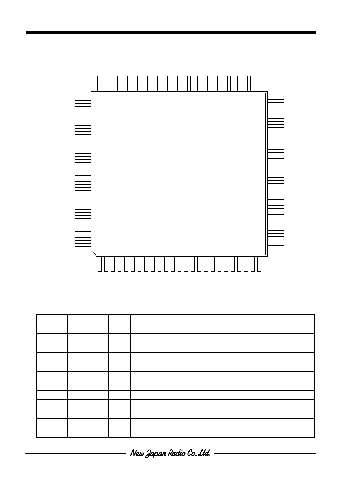
!PIN CONFIGURATION
!!
NJU9214
BUF
CL2
CH2
VREF3
VREF2
VREF1
CH1
CL1
INT1
INT2
SGND2
SGND1
AGND
IVSH
IVSL
ADP
OVX
OVH
VR7
VR6
VR5
VR4
VR3
VR2
V1
80
85
90
95
100
SEG25
SEG24
SEG23
SEG22
SEG21
CIF2
CIF1
BLD
SLEEP
VSSA
VDSP
VSSD
XT1
XT2BZTXD
DTR
SEG28
DSR
SEG26
SEG27
60657075
SEG20
55
NJU9214FG1
1
510152025
SEG19
SEG18
SEG17
50
45
40
35
30
SEG16
SEG15
SEG14
SEG13
SEG12
SEG11
SEG10
SEG9
SEG8
SEG7
SEG6
SEG5
SEG4
SEG3
SEG2
SEG1
COM4
COM3
CMO2
COM1
T3
T2
T1
RST
PON
RMSIN
ACOUT
VDDA
!!
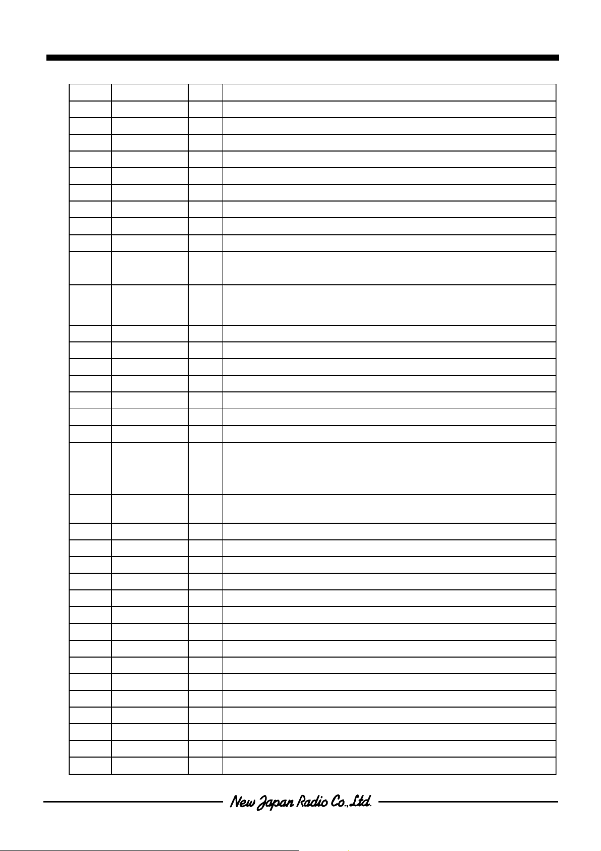
!TERMINAL DESCRIPTION
!!
.oNLOBMYSO/INOITCNUF
1TUOCAtuO)mpr,QRF,AmCA,ACAtadesu(lanimrettuptuorotaunettA
2ADDV- )V52.0±0.5=ADDV(DDVgolanA
3NISMRnIlanimreTtupnIegatloV-SMR
4DDDV- )V52.0±0.5=DDDV(DDVlatigiD
8ot54DRot1DRtuOlanimreTgnivirDyaleR
9SXTnIspb0042;Hspb0069;LlanimreTtceleSetaR-tuptuOC232SR
01XRTnIlanimreTtceleSnoitcnuFC232SR
11SMKnIlanimreTtceleSedoMyeK
21SMRnIlanimreTtceleSedoMlortnoCegnaR
02ot313CRot0CRnIk003(ecnatsiseRpu-lluPtupnIhtiwlanimreTtceleSegnaR Ω)
02ot714CFot1CFO/Ik003(ecnatsiseRpu-lluPtupnIhtiwlanimreTtceleSnoitcnuF Ω)
52ot125IKot1IKnI k003(ecnatsiseRpu-lluPtupnIhtiwlanimreTlortnoCnoitcnuFlanoitpO Ω)
FC1
FC2
FC3
FC4
KI1
RC1
RD3
RD4
TXS
RD2
RD1
VDDD
TRX
RC0
RMS
KMS
RC3
RC2
KI2
KI5
KI3
KI4
NJU9214
.oNLOBMYSO/INOITCNUF
62NOPnI 003(ecnatsiseRpu-lluPtupnIhtiwlanimreTesaeleRedoMffo-rewoPotuA Ω )k
72TSRnIk01(ecnatsiseRpu-lluPtupnIhtiwlanimreTteseRmetsyS Ω)
03ot823Tot1TnIk003(ecnatsiseRpu-lluPtupnIhtiwlanimreTtseT Ω)
43ot134MOCot1MOCtuOlanimreTnommoCDCL
26ot5382GESot1GEStuOlanimreTtnemgeSDCL
36RSDnIlanimreTydaeRteSataDC232SR
46RTDtuOlanimreTlanimreT-ataDC232SR
56DXTtuOlanimreTtuptuOataDC232SR
66ZBtuOlanimreTgnivirDrezzuBozeiP
762TXtuO)tuptuO(retrevnInoitallicsolatsyrC
861TXnI)tupnI(retrevnInoitallicsolatsyrC
lanimreTO/IegatlovgnivirdDCL
96PSDV0/I
07DSSV- V0=DSSVSSVlatigiD
17PEELStuO)leveL"H":ffo-rewoP(lanimreTlangisffo-rewoPotuA
27ASSV- V0.5-=ASSVSSVgolanA
37DLBnIV0.4<DLB:noitceteD,lanimreTrotceteDefiLyrettuB
57,471FIC,2FIC0/IlanimreTgnitcennocroticapacnoitargetnideeps-hgiH
67FUBtuOlanimreTtuptuoreffubrotargetnideeps-hgiH
87,772HC,2LC0/IlanimreTgnitcennocroticapacecnereferrotargetnideeps-hgiH
3FERV
18ot97
38,281LC,1HC0/I
58,482TNI,1TNI0/IlanimreTgnitcennocroticapacrotargetnietarucca-hgiH
78,681DNGS,2DNGSnIlanimreTgnisnesgolanA
88DNGA- lanimreTDNGgolanA
98HSVInIlanimreTgnisnes)A(tnemerusaemtnerruC
09LSVInIlanimreTgnisnes)Am(tnemerusaemtnerruC
19PDAnIlanimreTtupniretpadA
29XVOnI)ecnaticapaC,ytiunitnoC,ecnatsiseR(lanimreTgnisneS
39HVOtuO)ecnaticapaC,edoiD,ytiunitnoC,ecnatsiseR(lanimreTylppusegatloV
497RV0/IegnarV04,V4roflanimreTecnatsiseRredeelB
596RV0/I004roflanimreTecnatsiseRredeelB Ω egner
695RV0/Ik4,V0004roflanimreTecnatsiseRredeelB Ω egner
794RV0/Ik04,V004roflanimreTecnatsiseRredeelB Ω egner
893RV0/Ik004,V04roflanimreTecnatsiseRredeelB Ω egner
992RV0/Ik0004,V4roflanimreTecnatsiseRredeelB Ω egner
001IVnIegnarVm004roflanimreTtupniegatloV
ot
1FERV
nI
lanimreTtupni
"+";1HC,"-";1LC
5/3X)DSSV-DDDV(=PSDV:denepO
)DSSV-DDDV(=PSDV:DSSVotdetcennoC
lanimreTtupniegatlovecnereferrotargetnietarucca-hgiH:1FERV
lanimreTtupniegatlovecnereferrotargetnideeps-hgiH:2FERV
egatlovecnereferrotargetnitnemerusaemecnaticapaC:3FERV
lanimreTgnitcennocroticapacecnerefeRrotargetnietarucca-hgiH
!!
!FUNCTION DESCRIPTION
!!
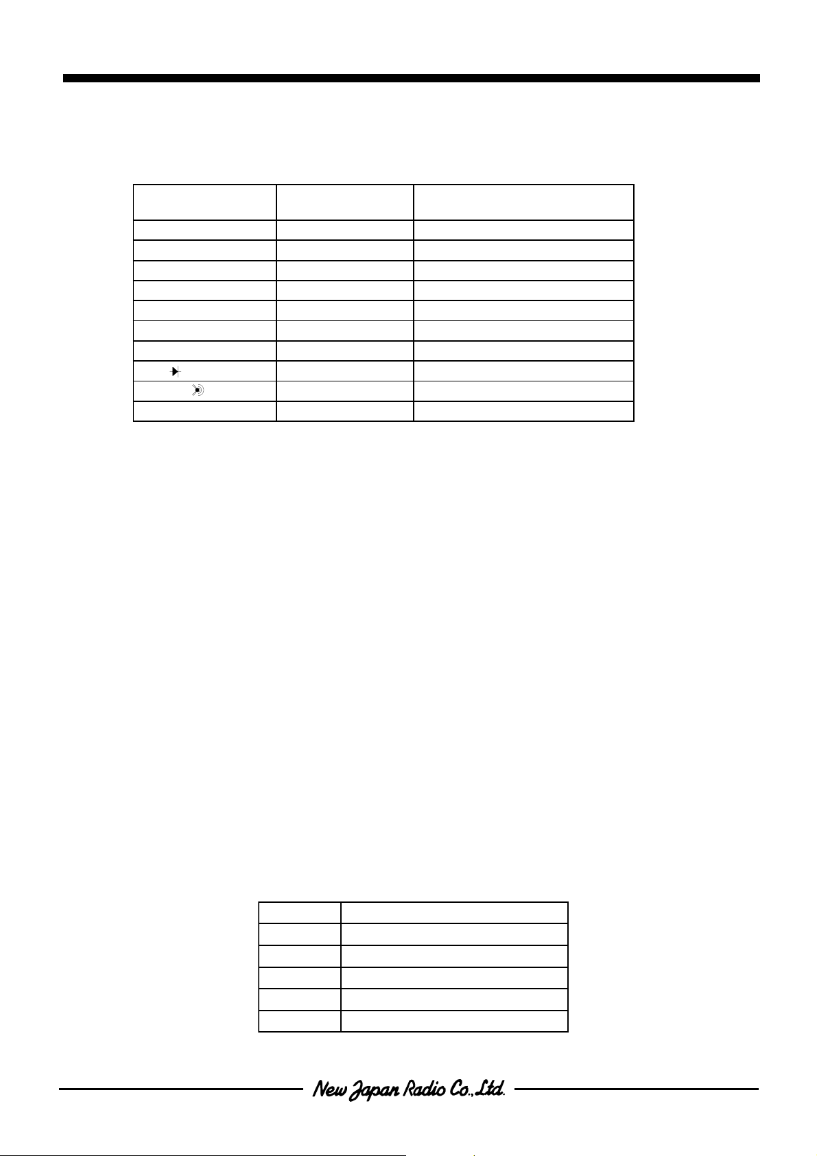
( 1 )Measurement function
Each measurement functions shown below is available with the NJU9214.
NJU9214
TNEMERUSAEM
NOITCNUF
egatloVCA/CDV0004otVm004egnar-5:launaM/egnar-4:otuA1*
tnerruCCA/CDAm0004otAm4egnar4-launaM/egnar2-launaM·otuA2*
tnerruCCA/CDA04dexiF
(ecnatsiseR Ω)004 Ω M04ot Ω egnar-6:launaM/egnar-6:otuA
)f(ycneuqerFzHk0001otzH001egnar-5:otuA
)C(ecnaticapaC004otFn4 µFegnar-6:launaM/egnar-6:otuA
)mpr(ohcaTmprK006otmpr0006egnar-3:otuA
)(edoiDdexiF
)(ytiunitnoCdexiF
PDAdexiF3*
*1 400mV range (AC/DC) is selected in only manual range.
*2 4mA-4000mA range has Auto/Manual-2range and Manual-4range mode, each mode
needs its own application circuit.
*3 ADP is applied for ºC, hfe and other measurement.
( 1 - 1 ) Voltage (DCV, ACV) measurements
The divided voltages which are output from each resistance R1 to R5 shown in following table are supplied to A/
D converter.
In the AC measurement, after the dividing voltage, these output voltages are converted to DC Voltages with the
external RMS/DC converter. This DC voltage is supplied into A/D converter.
10MΩ resistor for input terminal may be easy to be affected by noises.
Therefore 10MΩ and peripheral circuits require some protection like shields and so on for stable display .
The resistors for attenuating should be selected with a flat temperature characteristic. Especially , the resistors
(10MΩ, 10kΩ, 1kΩ) for 400V , 4000V ranges should be selected carefully. For example, when 4,000V is input,
0.4mA (4,000V÷10MΩ) flow through 10MΩ, and the resistor consumes power of 1.6W (4,000V×0.4mA) and the
temperature of the reference resistor.
After measuring at 400V, 4,000V ranges, sometimes the uncorrect value is shown on the display at 4V , 40V
ranges because the value of resister as the attenuator is changed by the temperature.
EGNARlaunaM/otuA
EGNARETARNOISIVID
)Vm004(1R1
)V4(2RM1 Ω M01/ Ω
)V04(3Rk001 Ω M01/ Ω
)V004(4RK01 Ω M01/ Ω
)V0004(5Rk1 Ω M01/ Ω
NJU9214
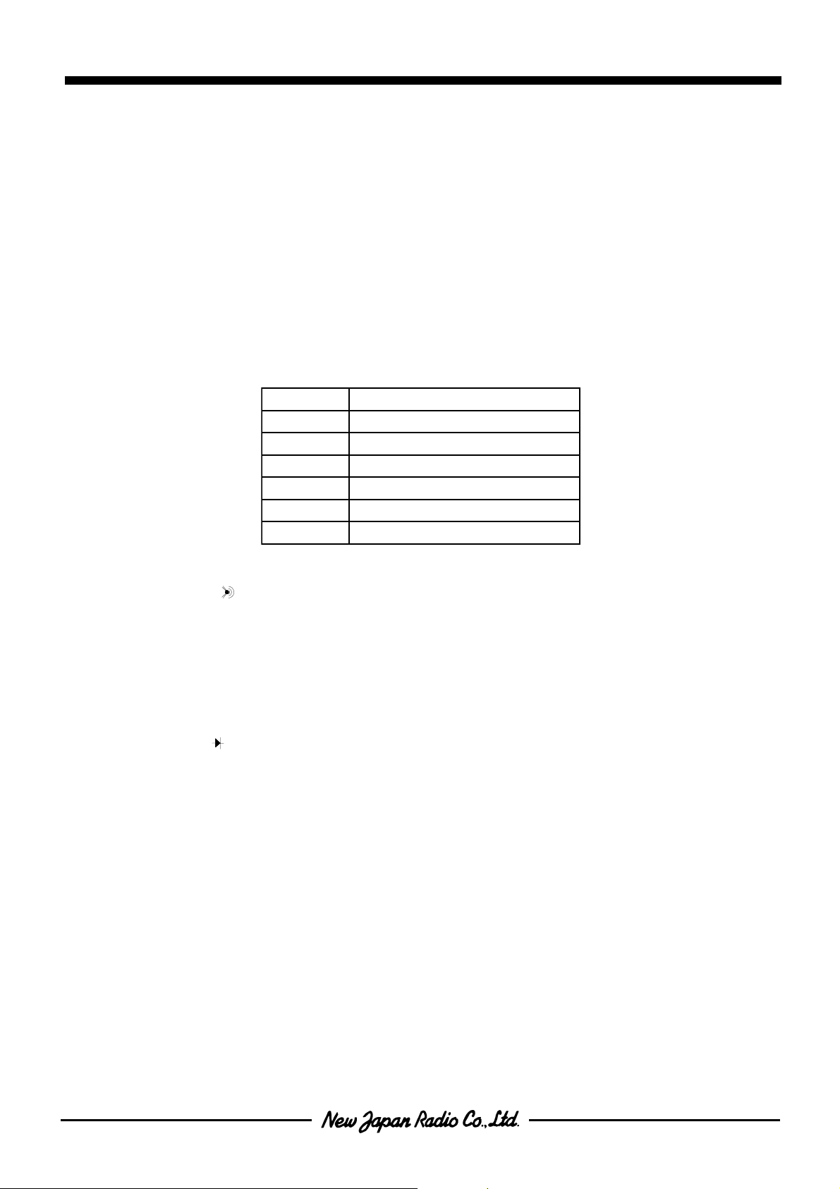
( 1 - 2 ) Resistance measurement(Ω)
As shown below, six type resistors ( 10MΩ,1MΩ,100kΩ,10kΩ,1kΩ,100Ω ) connecting VR2 to VR7 are used for
reference resistors of each range.
The output voltage on the measurement terminal is almost same as the voltage inputted Vref3.
As shown in Application circuits (1) to (3), an input protective diode must be connected with the OVH terminal.
In resistance measurement, continuity test, diode check and capacitance mode, if the NJU9214 is supplied high
voltage on the OVH terminal from the external, the NJU9214 may be broken completely .
In the R1 (400Ω) range, sometimes the resistor value shows wrong display because of the influence by test
leads and wiring resistances of a circuit board. In this case, it needs to adjust on the relative function using the 0
Ω resistance.
In the R6 (40MΩ) range, it may take a time to get the correct measurement value by the influence of parasitic
capacitance and may not show the stable value by the noise effects.
EGNAReulaVecnatsiseR.refeR
004(1R Ω)001 Ω
K4(2R Ω)k1 Ω
K04(3R Ω)k01 Ω
K004(4R Ω)k001 Ω
K0004(5R Ω)M1 Ω
K04(6R Ω)M01 Ω
( 1 - 3 ) Continuity test( )
The input attenuator is fixed to 400Ω range of the resistance measurement mode. When the value is less than
40Ω, the buzzer sounds. The output voltage on the measurement terminal is about 0.4V .
If the display doesn't show 0Ω by resistances of lead wire when the terminals are shorted,
this case requires adjustment at 0Ω using the relative function.
( 1 - 4 ) Diode check( )
The input attenuator is fixed to DC4V range. The output voltage on the OVH terminal is about 5V (VDDA), and it
is supplied to the measurement terminal through the SW1 (external switch or relay).
( 1 - 5 ) Current ( DCmA, ACmA ) measurement
Current measurement provides the Auto-Manual 2-range mode(RMS=H) and the Manual 4-range mode (RMS=L).
These are changed by status of the RMS terminal. Each mode needs its own application circuit.
In the Auto-manual 2-range mode, the sense terminal is IVSL terminal at the 40mA range and IVSH terminal at
the 400mA range.
In the Manual 4-range mode, the sense terminal is IVSL. In this mode, switching range is performed by changing
the reference resistors. The SW for the reference resistor change must be operated together with the SWs
connecting to ' RC1 to RC3 '. ( Refer to ( 2 - 1 - 3 ) )
( 1 - 6 ) Current ( DCA, ACA ) measurement
It is fixed to the 40A range. The sense terminal is the IVSH terminal.
NJU9214
( 1 - 7 ) Frequency ( f ) measurement
The input voltage is divided by the attenuator, and then the attenuator output is supplied to counter through the
buffer .
The divided voltage is converted to DC voltage by the external RMS/DC converter, and the dividing voltage ratio of
the input attenuator is changed by this DC voltage, Noises or distorted waveforms sometimes show different
display against actual frequency .
The frequency range is always fixed to the Auto-range mode. It is able to switch from 100Hz to 1,000kHz and
the measurement cycle is 1 time a second.
( 1 - 8 ) RPM measurement
It is possible to measure numbers of revolution like as the revolutions of engine. The measurement is same way
as the frequency measurement. The revolutions are calculated by the value of 60 times the frequency .
The revolution range is always selected one of 6,000 to 600krpm automatically .
The minimum input voltage ( wave amplitude ) is about 300mV and the measurement cycle is 1 time a second.
( 1 - 9 ) Capacitance ( C ) measurement
The constant-current charges the measured capacitor, and the charging time, while the voltage of capacitance
reaches to the reference voltage, is measured and converted to the capacitance value.
If the measured capacitor has any electric charges, accurate measurement is not available. Therefore the
measured capacitor must be discharged before measurement.
The sense terminal is the OVX terminal.
( 1 - 10 ) Adapter ( ADP ) measurement
The voltage between the ADP terminal and the SGND is supplied to the A/D converter directly . Both of ADP
terminal ( + ) and SGND terminal ( - ) are High-impedance in DC400mV range.
Therefore, it is also used as differential input.
( 2 ) Switch input Mode
The lock or push type input switch is applied for function selection. The switch type is selected in both of auto
and manual ranges by the RMS terminal setting.
When the push type switch is selected, auto ranging is always selected.
When the lock type switch is selected and the RMS terminal is GND ( L ) level, all ranges are selected by
switches. But if the RMS terminal is VDD level ( H ), auto range, manual range selection and the range set are
performed by a push type switch.
lanimreTSMKlanimreTSMRHCTIWSEGNAR
HH
HL launaM
L* epythsuPotuAlluF
epytkcoL
otuAlluF
eraCt'noD:*
Both of lock and push type application have the chattering protective function which reject the chattering less
than 20ms.
NJU9214
( 2 - 1 ) Lock type switch
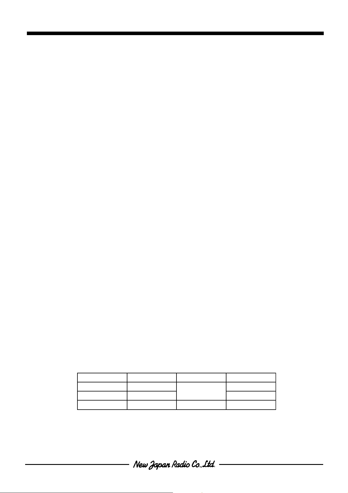
( 2 - 1 -1 ) Measurement function selection ( KMS = " H " )
The measurement function is set by FC1 to FC4 terminal. Excepting the following settings, all others select the
DCV measurement mode.
edomtnemerusaeM1CF2CF3CF4CF
VCD HHHH
VCA LHHH
AmCDHLHH
AmCALLHH
(ecnatsiseR Ω )H H L H
)(ytiunitnoCLHLH
)(edoiDHLLH
)C(ecnaticapaC LLLH
ACD HHHL
ACALHHL
)f(ycneuqerFHLHL
mprLLHL
PDAHHLL
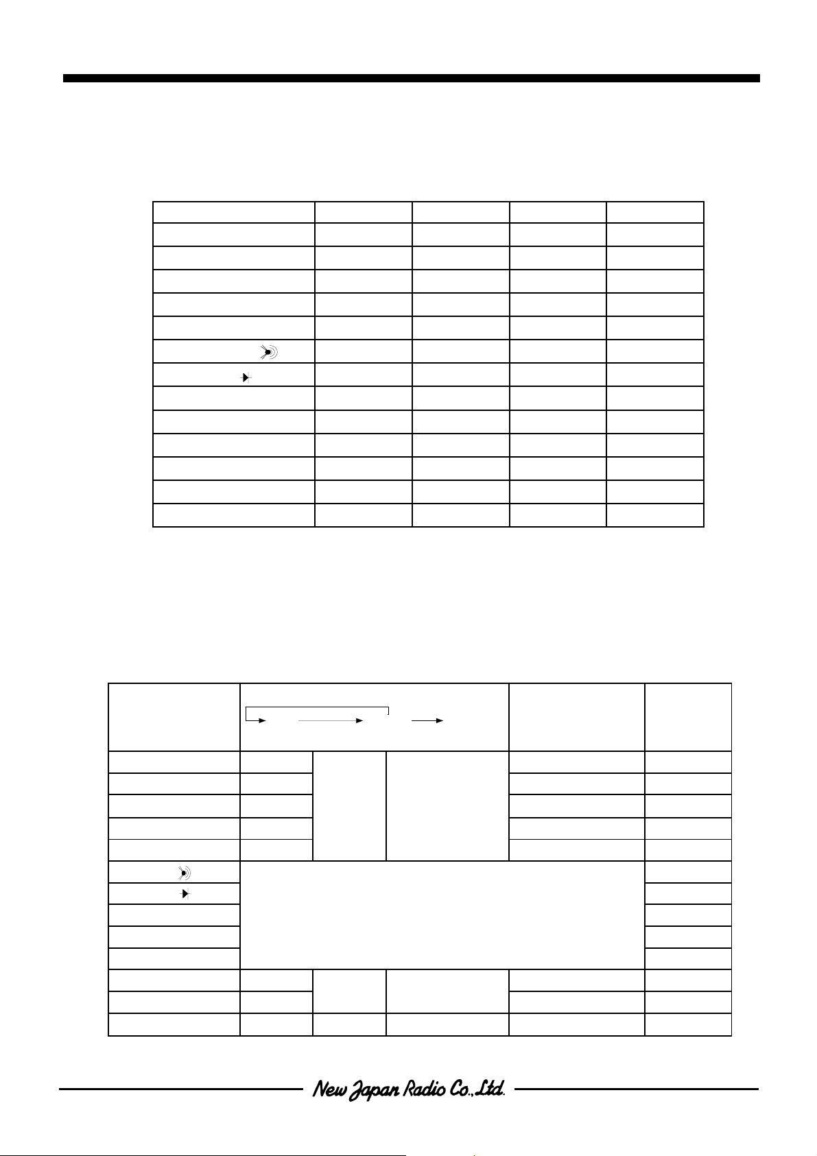
( 2 - 1 - 2 ) Range setting ( Lock type & Auto-Ranging : KMS = RMS = " H " )
The range shown in below table is controlled by a switch of the RC0 terminal which must go to "L" level ( GND )
when it is pressed. When the switch is pressed once, the range is changed from Auto-range to manual-range,
and its range is held. Then, the range is changed in every time by the switch operation. The range always returns
to Auto-range from any kinds of range when the switch is pressed over than 1 second.
1push(>1sec)
edoMtnemerusaeM lortnocgnignaR
VCDR
VCAR
AmCDR
AmCAR
(ecnatsiseR Ω )R
Auto
1push(<1sec)
Rot
2
5
Rot
2
5
Rot
2
3
Rot
2
3
Rot
1
6
→ DLOH
Manual
1push(<1sec)
Range up
R(5→R2)V0004otV4V4
R(5→R2)V0004otV4V4
iR → R(1+iR
R(3→R2)Am004otAm04Am04
R(6→R1)004 Ω M04ot Ω 004 Ω
)(ytiunitnoC
)Am004otAm04Am04
3→R2
tluafeD
egnaR
004 Ω
)(edoiD V4
PDA Vm004
DEXIF
ACD A04
ACA A04
)f(ycneuqerFR
)mpr(ohcaTR
)C(ecnaticapaCR
Rot
1
5
Rot
1
3
Rot
1
→ DLOH
6
iR → R(1+iR
egnar-otuA
)Fu004otFn4Fn4
6→R1
zHk9.999otzH001zH001
mprk006otmpr0006mpr0006
NJU9214
( Note ) Frequency measurement and revolution measurement are always set to the Auto-Range.
Ranges of continuity test ( ), diode check ( ), ADP, DCA and ACA measurement are always fixed to the
default ranges. Just after the power-on operation or mode changing, the range is set to the default range.
In the ADP measurement, three units are displayed by setting of RC1 to RC3 terminals.
The R1 to R6 of above range control table are set as a range corresponding to below table.
EGNARVCDVCAAmCDAmCA
R
1
R
2
R
3
R
4
R
5
R
6
Vm004Am004
V4*V4*Am04*Am04*k4 Ω zH000100006Fn04
V04V04Am004Am004k04 Ω zHk01k006Fn004
V004V004
V0004V0004
Ω
004* Ω zH001*0006*Fn4*
k004 Ω zHk001
k0004 Ω zHk0001
M04 Ω
fmprC
Fu4
Fu04
Fu004
(NOTE) The " * " mark means the default range.
Changing to DC400mA range or AC400mA is available by only manual operation. Auto-range operation cannot
change to these ranges.
( 2 - 1 - 3 ) Range setting ( Lock type switch & Manual-range : KMS = " H ", RMS = " L " )
The range setting shown in below table is available with RC1 to RC3 terminal.
1CR2CR3CRVCA,VCDAmCA,AmCD
Ω
HHH Am004Am4004 Ω Fn4
LHH V4Am04k4 Ω Fn04
HLH V04Am004k04 Ω Fn004
LLH V004Am0004k004 Ω Fu4
HHL V0004Am4k0004 Ω Fu04
LHL Vm004Am4M04 Ω Fu004
HLL Vm004Am4004 Ω Fn4
LLL Vm004Am4004 Ω Fn4
C
( NOTE ) Frequency and revolution measurements are always set to the Auto-range.
Ranges of continuity test ( ), diode check ( ), ADP, DCA and ACA measurement are always fixed to the
default ranges.
 Loading...