

JRC NJM3717D2, NJM3717FM2, NJM3717E2 Datasheet
STEPPER MOTOR DRIVER
■ GENERAL DESCRIPTION ■ PACKAGE OUTLINE
NJM3717 is a stepper motor diver, which consists of a LS-TTL
compatible logic input stage, a current sensor, a monostable
multivibrator and a high power H-bridge output stage with built-in
protection diodes.
The output current is up to 1200mA. Two NJM3717 and a small
number of external components form a complete control and drive
unit for stepper motor systems.
NJM3717D2
NJM3717
NJM3717E2
■ FEATURES
• Half-step and full-step modes
• Switched mode bipolar constant current drive
• Wide range of current control 5 - 1200 mA
• Wide voltage range 10 - 50 V
• Thermal overload protection
• Packages DIP16 / PLCC28 / EMP20
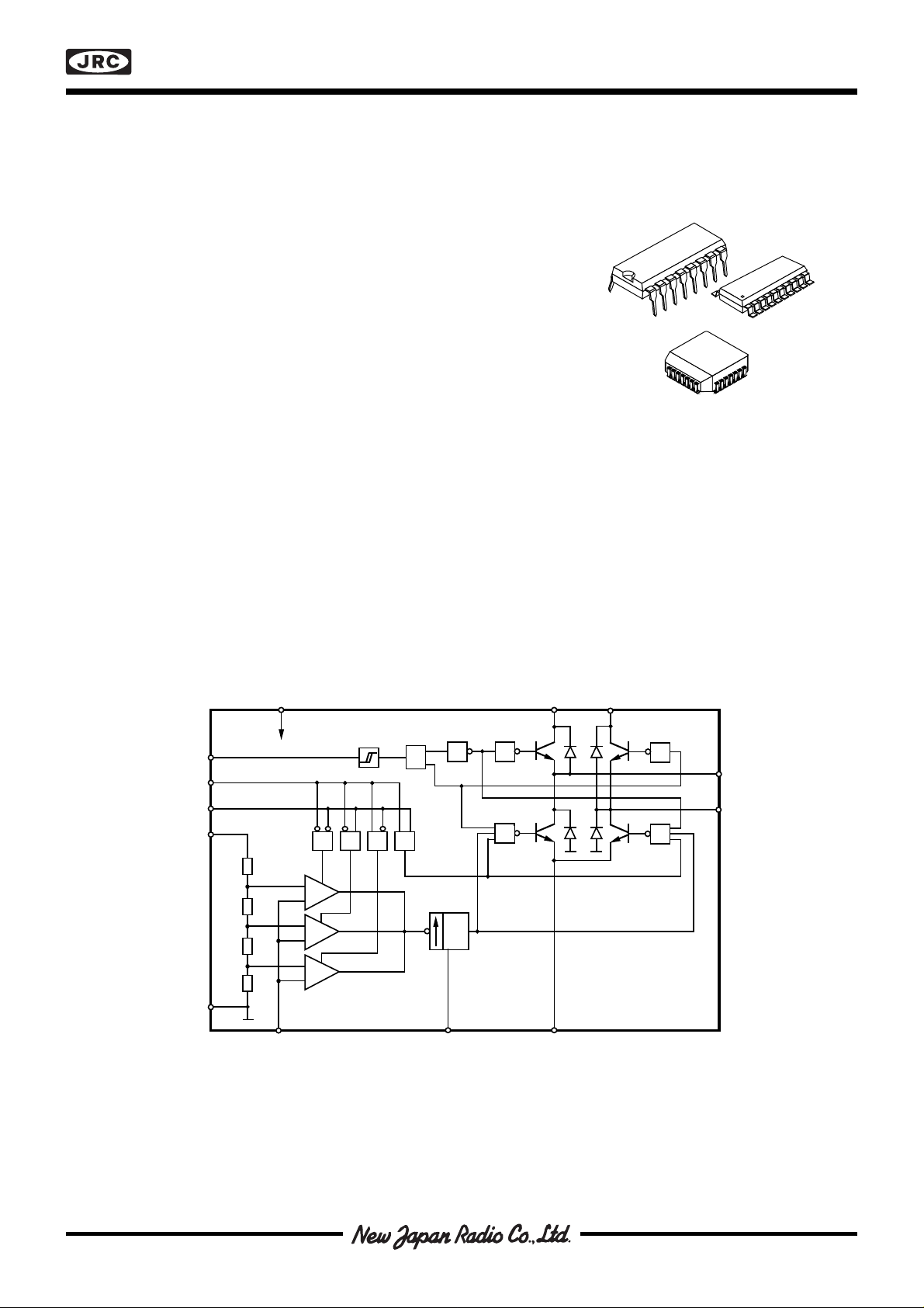
■ BLOCK DIAGRAM
V
CC
Schmitt
Phase
I
1
I
0
V
R
Trigger
& &&&
Time
Delay
1 1
≥ 1
NJM3717FM2
V
MM
V
MM
1
M
A
M
B
≥ 1
GND
Figure 1. Block diagram
+
–
+
–
+
–
Current Sensor
Monostable
t = 0.69 • R • C
off
T
Output Stage
T T
NJM3717
E
N/C
A
N/C
E
GND
B
T
N/C
V
C
N/C
I
Phase
I
V
GND
GND
GND
GND
N/C
N/C
MM
GND
GND
GND
GND
GND
CC
5
6
7
8
9
10
11
25
24
23
22
21
20
19
432
1
282726
12131415161718
MM
R
0
1
V
V
M
M
NJM3717FM2
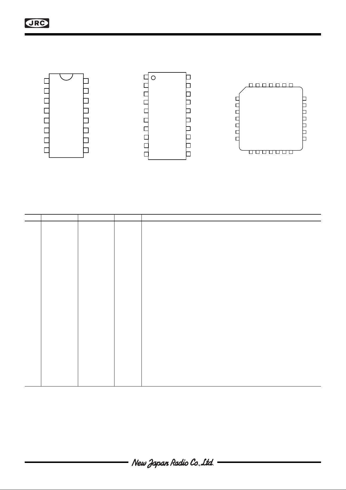
■ PIN CONFIGURATIONS
M
V
MM
GND
GND
V
CC
Phase
B
T
I
1
1
2
3
NJM
4
3717D2
5
6
7
8
E
16
M
15
V
14
GND
13
GND
12
V
11
C
10
I
9
Figure 2. Pin configurations
0
A
MM
R
M
V
MM
GND
GND
GND
GND
V
CC
Phase
NJM3717
1
B
T
2
3
4
5
NJM
3717E2
6
7
8
I
1
9
10
20
E
19
M
A
18
V
MM
17
GND
16
GND
15
GND
14
GND
13
V
R
12
C
11
I
0
■ PIN DESCRIPTION
DIP EMP PLCC Symbol Description
11 10M
2 2 11 T Clock oscillator. Timing pin connect a 56 kΩ resistor and a 820 pF in
3,14 3,18 12,4 V
4,5, 4,5,6,7,14 1,2,3,9,13, PCB.
12,13 15,16,17 14,15,16,17 GND Ground and negative supply. Note these pins are used for heatsinking.
28 Make sure that all ground pins are soldered onto a suitable large copper
68 18V
79 19I
8 10 20 Phase Controls the direction of the motor current of M
911 21 I
10 12 23 C Comparator input. This input senses the instantaneous voltage across the
11 13 24 V
15 19 6 M
16 20 8 E Common emitter. Connect the sense resistor between this pin and ground.
Motor output B, Motor current flows from MA to MB when Phase is high.
B
parallel between T and Ground.
Motor supply voltage, 10 to 45 V. V
MM
pins should be wired together on
MM
ground plane for efficient heat sinking.
Logic voltage supply normally +5 V.
CC
Logic input, it controls, together with the I0 input, the current level in the
1
output stage. The controllable levels are fixed to 100, 60, 20, 0%.
and MB outputs. Motor
current flows from MA to MB when the phase input is high.
Logic input, it controls, together with the I1 input, the current level in the
0
output stage. The controlable levels are fixed to 100, 60, 20, 0%.
A
sensing resistor, filtered through a RC Network.
Reference voltage. Controls the threshold voltage of the comparator and
R
hence the output current. Input resistance: typically 6.8kΩ ± 20%.
Motor output A, Motor current flows from MA to MB when Phase is high.
A
| V – V |
MA MB
NJM3717
t
off
t
t
d
t
t
D =
on
+
t
t
on
off
50 %
V
CH
V
E
f =
s
t
ontoff
t
on
1
+
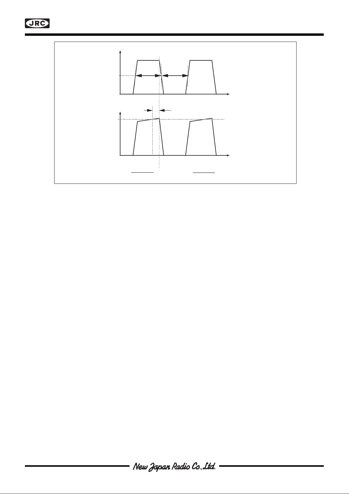
Figure 3. Definition of terms
■ FUNCTIONAL DESCRIPTION
The NJM3717 is intended to drive a bipolar constant current through one motor winding of a 2-phase stepper
motor.
Current control is achieved through switched-mode regulation, see figure 4 and 5.
Three different current levels and zero current can be selected by the input logic.
The circuit contains the following functional blocks:
• Input logic
• Current sense
• Single-pulse generator
• Output stage
Input logic
Phase input. The phase input determines the direction of the current in the motor winding. High input forces the
current from terminal MA to MB and low input from terminal MB to MA. A Schmitt trigger pro vides noise immunity and
a delay circuit eliminates the risk of cross conduction in the output stage during a phase shift.
Half- and full-step operation is possible.
Current level selection. The status of I0 and I1 inputs determines the current level in the motor winding. Three fixed
current levels can be selected according to the table below.
Motor current I
I
0
1
High level 100% L L
Medium level 60% H L
Low level 20% L H
Zero current 0% H H
The specific values of the different current levels are determined by the reference voltage VR together with the value
of the sensing resistor RS.
The peak motor current can be calculated as follows:
im = (VR • 0.083) / RS [A], at 100% level
im = (VR • 0.050) / RS [A], at 60% level
im = (VR • 0.016) / RS [A], at 20% level
The motor current can also be continuously varied by modulating the voltage reference input.
 Loading...