

JRC NJM2199V, NJM2199M, NJM2199D Datasheet
SRS 3D SURROUND AUDIO PROCESSOR
■■■■
GENERAL DESCRIPTION
The
NJM2199
regenerating the 3D surround sound with two speakers.
It regenerates 3D surround sound from stereo input
only.
The features of wide operating voltage range, wide
dynamic range, low output noise are suitable for any
audio applications.
■■■■
FEATURES
● Operating Voltage (4.7 to 13V)
● Low Supply Current (5.7mA typ. at 3D Stereo mode)
● Low Output Noise (32µVrms typ. at 3D Stereo mode)
● BYPASS Gain (0dB typ.)
● BYPASS FUNCTION (Through)
● WIDTH control
● Internal Mode Control Switch (2bit)
● Bipolar Technology
● Package Outline DIP14, DMP14, SSOP14
is a SRS 3D surround audio processor
PRELIMINARY
■■■■
PACKAGE OUTLINE
NJM2199M
NJM2199
NJM2199D
NJM2199V
The SRS technology right incorporated in the NJM2199 are owned by SRS Labs, a U.S. Corporation and licensed to New Japan
Radio Co., Ltd. SRS is protected under U.S. and foreign patents issued and/or pending. SRS and the , are trademarks of SRS
Labs, Inc. in the United States and selected foreign countries. Neither the purchase of the NJM2199, nor the corresponding sale of
audio enhancement equipment conveys the right to sell commercialized recordings made with any SRS technology.
SRS Labs requires that all users of the NJM2199 must enter into a license agreement directly with SRS Labs if the royalty is not
included in the purchase price. SRS Labs also requires any users to comply with all rules and regulations as outlined in the SRS
Trademark Usage Manual.
For further informati on, please contact:
SRS Labs, Inc.
2909 Daimler Street. Santa Ana, CA 92705 USA
Tel:714-442-1070 Fax:714-852-1099 http://www.srslabs.com
- 1 -
NJM2199
■■■■
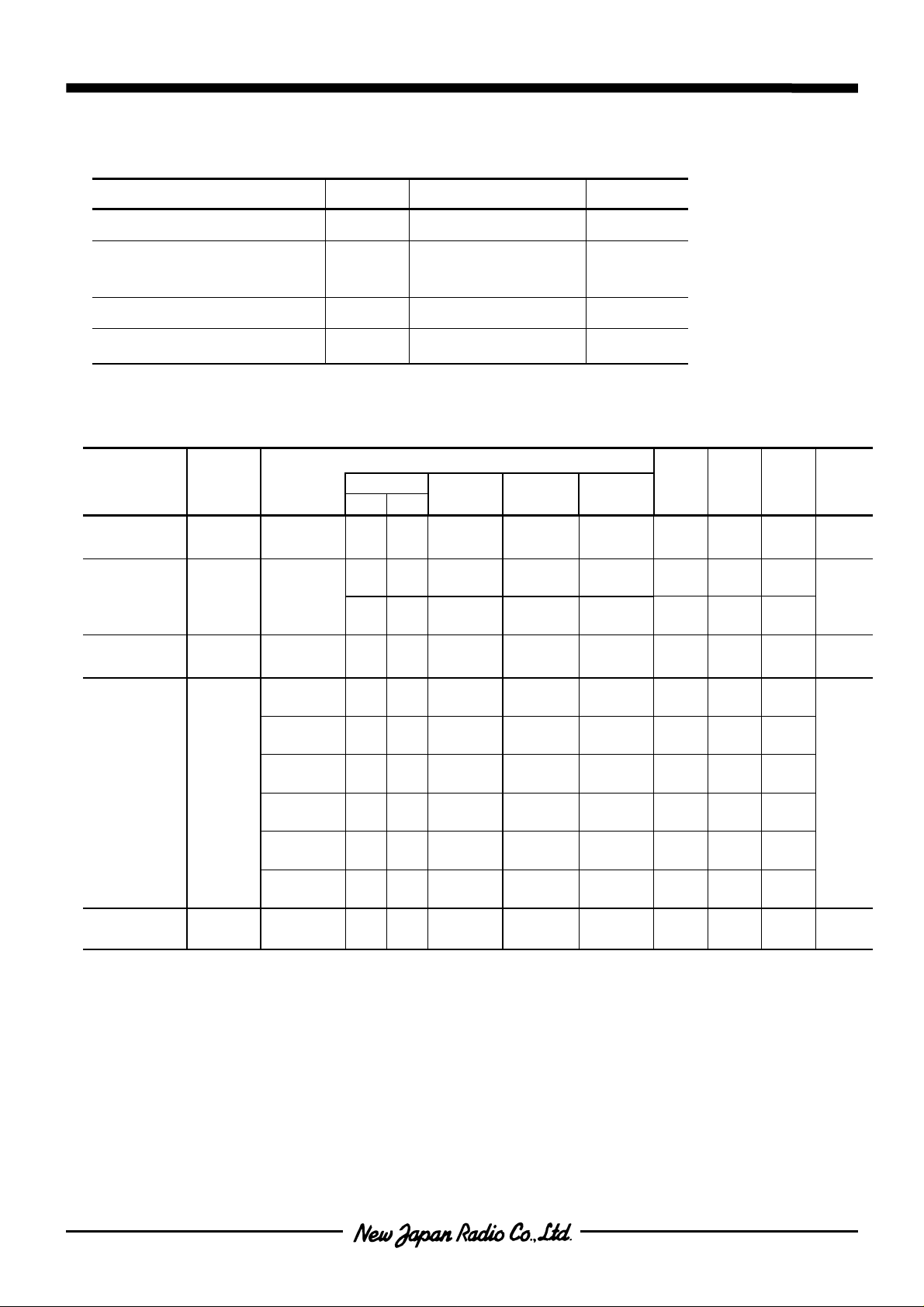
AB SOLUTE MAXIMUM RATING
PARAMETER
Supply Voltage
Power Dissipation
Operating Temperature Range
Storage Temperature Range
■■■■
ELECTRICAL CHARACTERISTICS
PARAMETER SYMBOL
Operating
Voltage
Operating
Current
Reference
Voltage
Maximum
Input Voltage
Channel
Valance
V+ - - - - - 4.7 12.0 13.0 V
V
V
CH
I
cc
REF
INMAX
No Signal
V+/2 - - - - - 5.8 6.0 6.2 V
f=1kHz
T.H.D.=3%
f=125Hz
T.H.D.=3%
f=125Hz
T.H.D.=3%
f=125Hz
T.H.D.=3%-V
f=125Hz
T.H.D.=3%
f=125Hz
T.H.D.=3%
f=1kHz
BAL
L-R Output-V
(Ta=25°C)
SYMBOL
V+
(DIP14) 500
P
D
T
opr
T
stg
(DMP14) 350
(SSOP14) 300
(V+=12V,Ta=25°C, V
TEST CONDITION
INPUT
LR
- - - BYPASS - 2.9 5.7 8.6
-- -
V
--V
V
--V
V
--V
V
-
V
V
V
V
VV-V
-V
V
-
RATINGS
15
-40 to +85
-40 to +125
=-10dBV(316mVrms) unless otherwise noted)
IN
OUTPUT MODE
3D
Stereo
L
R
L
R
L
R
L
R
L
R
L
R
L
R
BYPASS -
3D
Stereo
3D
Stereo
3D
Stereo
3D
Stereo
3D
Stereo
3D
Stereo
UNIT
V
mW
°C
°C
WIDTH
VOLUME
MAX 2.9 5.7 8.6
MAX
MIN -
MAX -
MAX -
MAX
MAX -1.0 0.0 1.0 dB
MIN. TYP. MAX. UNIT
10.0
(2.51)
-1.5
(0.84)
-7.50
(0.42)
12.0
(3.98)
0.50
(1.08)
11.5
(3.76)
0.45
(1.05)
11.9
(3.94)
-5.50
(0.53)
mA
-
-
dBV
(Vrms)
-
-
-
- 2 -
NJM2199
■■■■
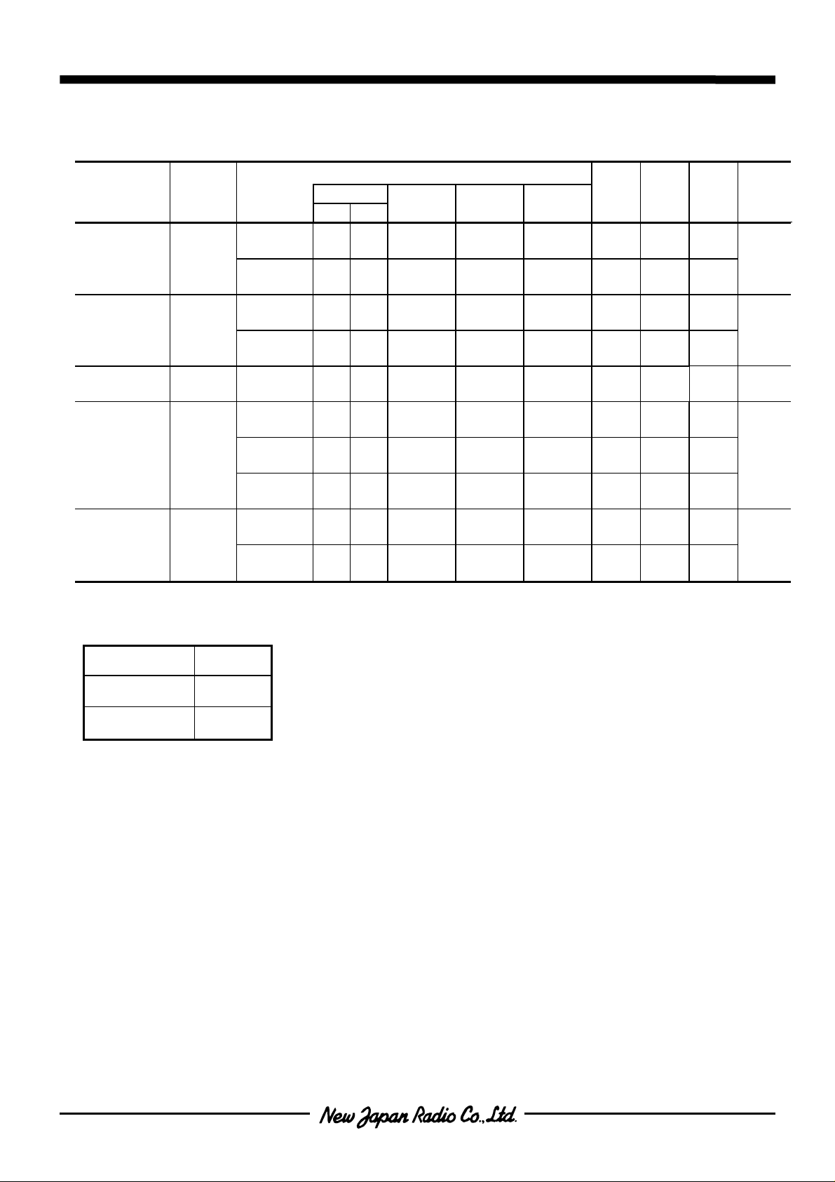
ELECTRICAL CHARACTERISTICS
PARAMETER SYMBOL
Rg=0
Ω
Output Noise V
Total
Harmonic
Distortion
Bypass Gain G
SRS Gain G
Mode Select
Control
Voltage
NOISE
T.H.D
Bypass
SRS
V
MODE
A-Weighte
Rg=0
Ω
A-Weighte
f=1kHz
f=1kHz
f=1kHz
f=125Hz
f=125Hz
f=125Hz
VIN =
High Level
VIN =
Low Level
■■■■
MODE SWITCH
(V+=12V,Ta=25,°C unless otherwise noted)
TEST CONDITION
INPUT
LR
00
00
V
--V
V
--V
V
--V
V
--V
V
--V
-
V
-- - - - 2.0 - V+
- - - - - 0.0 - 0.7
OUTPUT MODE
L
R
L
R
L
R
L
R
L
R
L
R
L
R
V
-
L
R
BYPASS - -
3D
Stereo
BYPASS - - 0.005 0.01
3D
Stereo
BYPASS - -1.0 0.0 1.0 dB
3D
Stereo
3D
Stereo
3D
Stereo
WIDTH
VOLUME
MAX -
MAX - 0.1 1.0
MAX 9.4 11.4 13.4
MIN -1.5 0.5 2.5
MAX 6.8 8.8 10.8
MIN. TYP. MAX. UNIT
-110
(3.16)
-90
(31.6)
-95
(17.8)
-85
(56.2)
dB
µVrms
(
%
dB
V
)
MODE MODE
BYPASS L
3D Stereo H
- 3 -
 Loading...