

Page 1
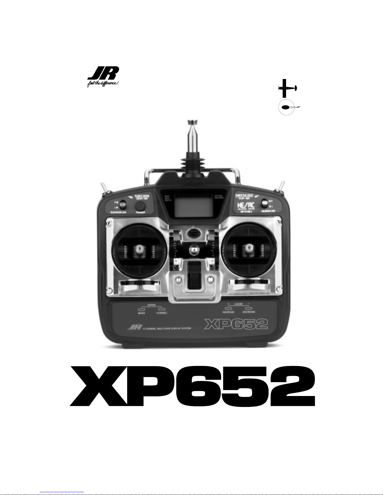
6-CHANNEL COMPUTER RADIO
INSTRUCTION MANUAL
FOR AIRPLANE AND
HELICOPTER
Page 2

Page 3

3
XP652 MANUAL Decal Sheet
Included with the XP652 radio system is a switch/function
decal sheet. These decals have been provided as a guide
to specific switch positions, functions, and abbreviations
used when operating the XP652.
The four small decals help identify switch positions and
use for helicopter and aircraft modes.
The large decal at the bottom of the sheet gives
abbreviations and definitions for all of the aircraft and
helicopter functions. The functions decal will prove to be
a helpful guide for making program changes to your
XP652 both in the shop and at the flying field.
We strongly encourage all prospective and current R/C
aircraft pilots join the Academy of Model Aeronautics. The
AMA is a non-profit organization which provides services
to model aircraft pilots. As an AMA member you will
receive a monthly magazine entitled MODEL AVIATION, as
well as a liability insurance plan to cover against possible
accident or injury. All AMA charter aircraft clubs require
individuals to hold a current AMA sporting license prior to
operation of their models. For further information you can
contact the AMA at:
Academy of Model Aeronautics
5151 East Memorial Drive
Muncie, IN 47302
(317) 287-1256
Thank you for purchasing the JR XP652 6-Channel Radio
System. This unit has been designed to provide the
modeler with a high quality, user friendly radio system
that can be depended upon for years to come.
It is important that you carefully read this manual before
attempting to operate your XP652 System. Please pay
particular attention to Page 13, Chapter 4 Charging Your
XP652 Radio System Prior to Installing.
XP652 SWITCH FUNCTION DECAL SHEET
AMA INFORMA TION
FLAP
UP
DOWN
OFF
ON
MIX
OR
GEAR
DOWN
UP
OFF
ON
MIX
OR
THROTTLE HOLD
NORMAL
HOLD
FLIGHT MODE
NORMAL
STUNT
DECAL SHEET
HELICOPTER
DECAL POSITION
Top View (Mode II)
AIRPLANE
DECAL POSITION
Top View (Mode II)
REAR DECAL POSITION
Airplane and Helicopter
INTRODUCTION TO THE XP652 RADIO SYSTEM
XP652 FUNCTION GUIDE
Tx BACK
HELI
TOP
LEFT
NORMAL
STUNT
FLIGHT MODE
NORMAL
STUNT
THROTTLE HOLD
AIR
TOP
LEFT
HELI
TOP
RIGHT
AIR
TOP
RIGHT
MIX OR FLAP
DOWN OFF
UP ON
OFF DOWN
ON UP
GEAR OR MIX
Airplane
REV Servo Reversing
D/R Dual Rates
EXP Exponential
SB-TRIM Sub-Trim
TRV ADJ Travel Adjustment
MIX A-R Aileron/Rudder Mix
MIX E-F Elevator/Flap Mixing
MIX DIF Differential
OFFSET Flap/Elevator Offset
MIX A Programmable Mix A
MIX B Programmable Mix B
MIX C Programmable Mix C
OFFSET Trim Offset Memory
Helicopter
REV Servo Reversing
D/R Dual Rates
EXP Exponential
SB-TRIM Sub-Trim
TRV ADJ Travel Adjustment
HLD Throttle Hold
PLN Pitch Low Normal
P2N Pitch Med. Normal
PHN Pitch High Normal
PLS Pitch Low Stunt
P2S Pitch Med. Stunt
PHS Pitch High Stunt
PLH Pitch Low Hold
P2H Pitch Med. Hold
PHH Pitch High Hold
TLN Throttle Low Norm.
T2N Throttle Med. Norm.
THN Throttle High Norm.
TLS Throttle Low Stunt
T2S Throttle Med. Stunt
MIX Revo Mixing
RVU Revo Mixing Up
RVD Revo Mixing Down
MIX A Programmable Mix A
STT Stunt Trim
CCP CCPM Swashplate Mix
Offset Trim Offset Memory
XP652 FUNCTION GUIDE
TxBACK
HELI
TOP
LEFT
NORMAL
STUNT
FLIGHT MODE
NORMAL
STUNT
THROTTLEHOLD
AIR
TOP
LEFT
HELI
TOP
RIGHT
AIR
TOP
RIGHT
MIX OR FLAP
DOWN OFF
UP ON
OFF DOWN
ON UP
GEAR OR MIX
Airplane
REV Servo Reversing
D/R Dual Rates
EXP Exponential
SB-TRIMSub-Trim
TRV ADJTravel Adjustment
MIX A-RAileron/Rudder Mix
MIX E-F Elevator/Flap Mixing
MIX DIF Differential
OFFSET Flap/Elevator Offset
MIX A Programmable Mix A
MIX B Programmable Mix B
MIX C Programmable Mix C
OFFSET Trim Offset Memory
Helicopter
REV Servo Reversing
D/R Dual Rates
EXP Exponential
SB-TRIMSub-Trim
TRV ADJTravel Adjustment
HLD Throttle Hold
PLN Pitch Low Normal
P2N Pitch Med. Normal
PHN Pitch High Normal
PLS Pitch Low Stunt
P2S Pitch Med. Stunt
PHS Pitch High Stunt
PLH Pitch Low Hold
P2H Pitch Med. Hold
PHH Pitch High Hold
TLN Throttle Low Norm.
T2N Throttle Med. Norm.
THN Throttle High Norm.
TLS Throttle Low Stunt
T2S Throttle Med. Stunt
MIX Revo Mixing
RVU Revo Mixing Up
RVD Revo Mixing Down
MIX A Programmable Mix A
STT Stunt Trim
CCP CCPM Swashplate Mix
Offset Trim Offset Memory
FM TX
72MHz
PLN
AIRPLANE
P2N
REV – Servo Reversing
PHN
D/R – Dual Rates
PLS
SB-TRIM – Sub-Trim
P2S
PHS
TRV ADJ – Travel Adjustment
PLH
MIX A-R – Ailer./Rudder Mixing
P2H
MIX E-F – Elevator/Flap Mixing
PHH
OFFSET – Landing Elev. Offset
TLN
T2N
THN
HELICOPTER
TLS
REV – Servo Reversing
T2S
D/R – Dual Rates
MIX
SB-TRIM – Sub-Trim
TRV ADJ – Travel Adjustment
HLD – Throttle Hold
RVU
RVD
OFFSET – Rudder Offset
– Pitch Low Normal
– Pitch Med. Normal
– Pitch High Normal
– Pitch Low Stunt
– Pitch Med. Stunt
– Pitch High Stunt
– Pitch Low Hold
– Pitch Med. Hold
– Pitch High Hold
– Throttle Low Norm.
– Throttle Med. Norm.
– Throttle High Norm.
– Throttle Low Stunt
– Throttle Med. Stunt
– Revo Mixing
– Revo Mixing Up
– Revo Mixing Down
Page 4
4
XP652 MANUAL Quick Start
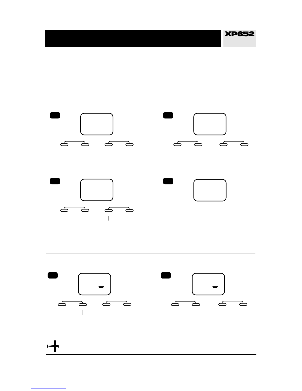
QUICK START
AIRPLANE
Model T ype Selection
Servo Reversing
THR
REV◆NORM
INCREASE
CLEAR
+–
DECREASE
INCREASE
CLEAR
+–
DECREASE
MODE
ENTER
CHANNEL
Press the MODE and CHANNEL
buttons simultaneously until a
beep is heard.
5
THR
MODE
ENTER
CHANNEL
Press the MODE button
until REV◆NORM
appears on the screen.
6
REV◆NORM
Turn the transmitter off and then on again.
MODE
ENTER
CHANNEL
Press the MODE and CHANNEL
buttons simultaneously and hold
while turning on the transmitter.
INCREASE
CLEAR
+–
DECREASE
INCREASE
CLEAR
+–
DECREASE
INCREASE
CLEAR
+–
DECREASE
1
AC
TYP
MODE
ENTER
CHANNEL
Press the MODE button
until TYP appears on the
screen.
2
AC
TYP
MODE
ENTER
CHANNEL
If AC appears on the screen
procede directly to Step 4. If HE appears
press the INCREASE or DECREASE
button until AC appears.
3
AC
TYP
4
9.7V
ACI
In this manual you will find in-depth instructions that
detail all the steps and procedures you should follow in
order to program each of the XF652's features. For
modelers who want to get into the air fast, we have
provided Quick Start. Quick Start covers the basic
programming information necessary to get you airborne.
Later, when you want to learn more about specific
features of the XP652, turn to the appropriate page(s) in
this manual for more detailed programming information.
If AC appears on the screen procede directly to
Step 4. If HE appears press the INCREASE or
DECREASE button until AC appears, then
press the MODE and CHANNEL buttons
simultaneously to store the model type change.
Page 5
5
XP652 MANUAL Quick Start
QUICK START
AIRPLANE
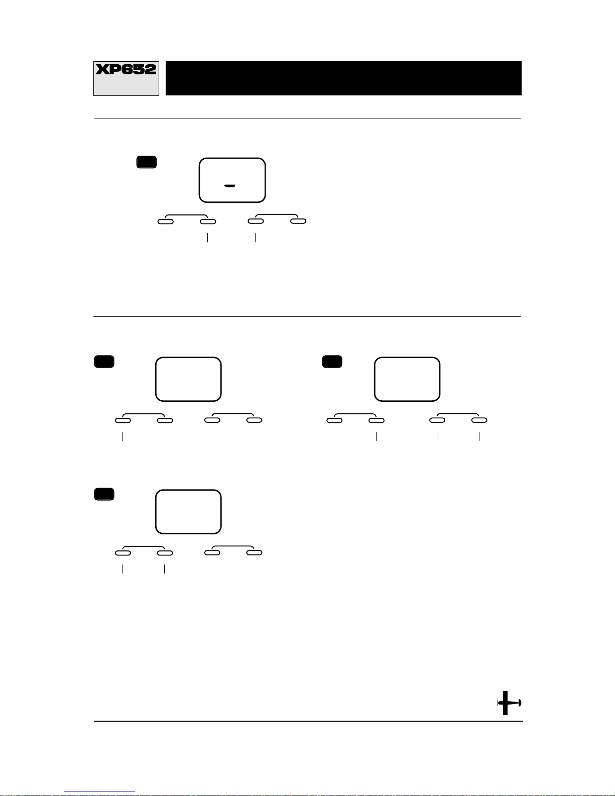
Servo Reversing continued
T ravel Adjustment
MODE
ENTER
CHANNEL
Press the MODE button
until TRV ADJ. appears
on the screen.
8
–I00
%
AIL
MODE
ENTER
CHANNEL
Press the
CHANNEL
button to select
the channel you
want the travel
adjusted on.
To decrease the
travel, move the stick
(i.e. aileron) to the
right then press the
DECREASE button
to adjust the right
travel. Release the
DECREASE button
and move the same
stick to the left. Press
the DECREASE
button to adjust the
left travel.
To increase the
travel, move the stick
(i.e. aileron) to the
right then press the
INCREASE button to
adjust the right
travel. Release the
INCREASE button
and move the same
stick to the left. Press
the INCREASE
button to adjust the
left travel.
9
MODE
ENTER
CHANNEL
Press the MODE and
CHANNEL buttons
simultaneously to return to
the model type display.
Before flying check the
direction of all control
surfaces and that the travel
is adjusted properly.
10
I0.4V
ACI
TRV ADJ.
–I02
%
AIL
TRV ADJ.
INCREASE
CLEAR
+–
DECREASE
INCREASE
CLEAR
+–
DECREASE
INCREASE
CLEAR
+–
DECREASE
THR
REV◆NORM
MODE
ENTER
CHANNEL
Press the
CHANNEL button
to select the
channel you want
to reverse.
Press the
INCREASE button
to reverse the
direction of the
channel you
selected.
7
INCREASE
CLEAR
+–
DECREASE
Press the
CHANNEL button
to select the
channel on which
you want the
travel adjusted.
Page 6
6
XP652 MANUAL Quick Start
QUICK START
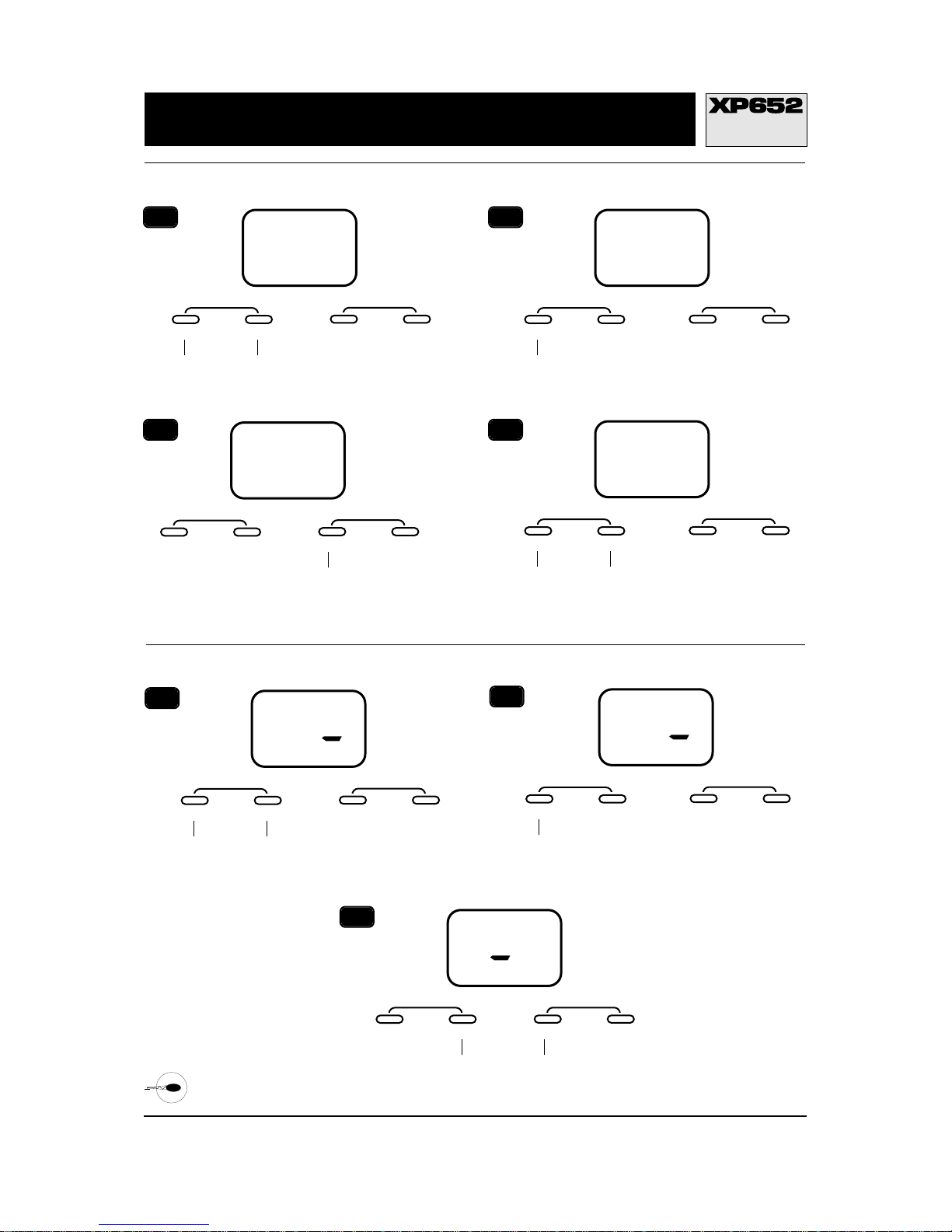
HELICOPTER
Model T ype Selection
Servo Reversing
THR
REV◆NORM
THR
REV◆NORM
MODE
ENTER
CHANNEL
Press the CHANNEL
button to select the
channel you want
to reverse.
Press the INCREASE
button to reverse the
direction of the channel
you selected.
7
MODE
ENTER
CHANNEL
Press the MODE and CHANNEL
buttons simultaneously until a
beep is heard. REV◆NORM
should appear on the screen.
5
THR
MODE
ENTER
CHANNEL
Press the MODE button
until REV
◆
NORM appears
on the screen.
6
REV◆NORM
INCREASE
CLEAR
+–
DECREASE
INCREASE
CLEAR
+–
DECREASE
INCREASE
CLEAR
+–
DECREASE
MODE
ENTER
CHANNEL
Press the MODE and CHANNEL
buttons simultaneously and hold
while turning on the transmitter.
1
AC
TYP
MODE
ENTER
CHANNEL
Press the MODE button until
TYP appears on the screen.
2
AC
TYP
MODE
ENTER
CHANNEL
If HE appears on the screen
procede directly to Step 4. If AC
appears press the INCREASE
button until HE appears.
3
HE
TYP
4
INCREASE
CLEAR
+–
DECREASE
INCREASE
CLEAR
+–
DECREASE
MODE
ENTER
CHANNEL
Press the MODE and CHANNEL
buttons simultaneously until a
beep is heard.
9.7V
HEI
INCREASE
CLEAR
+–
DECREASE
INCREASE
CLEAR
+–
DECREASE
Page 7
7
XP652 MANUAL Quick Start
QUICK START
HELICOPTER
T ravel Adjustment
Pitch Curve
Revolution Mixing
MODE
ENTER
CHANNEL
Press the MODE button until
TRV ADJ. appears on the screen.
8
–I00
%
AIL
TRV ADJ.
INCREASE
CLEAR
+–
DECREASE
MODE
ENTER
CHANNEL
Press the
CHANNEL
button to select
the channel you
want the travel
adjusted on.
To decrease the
travel, move the stick
(i.e. aileron) to the
right then press the
DECREASE button
to adjust the right
travel. Release the
DECREASE button
and move the same
stick to the left. Press
the DECREASE
button to adjust the
left travel.
To increase the
travel, move the stick
(i.e. aileron) to the
right then press the
INCREASE button to
adjust the right
travel. Release the
INCREASE button
and move the same
stick to the left. Press
the INCREASE
button to adjust the
left travel.
9
–I02
%
AIL
TRV ADJ.
INCREASE
CLEAR
+–
DECREASE
MODE
ENTER
CHANNEL
Press the MODE button
until PLN appears on
the screen.
10
0
%
MODE
ENTER
CHANNEL
Press the CHANNEL
button to select stick
position (point location).
Press the INCREASE or DECREASE
button to adjust the point value at the
selected stick position.
11
MODE
ENTER
CHANNEL
Press the MODE
button until Mix
RVU appears on
the screen.
Revolution mixing value
can be set for up or down.
Press the CHANNEL
button until U or D
appears on the screen.
Press the INCREASE button
to set the desired value of
the up and down positions.
A good place to start is
35% up and 35% down.
To change the direction of the
mixing value press the
INCREASE and DECREASE
buttons simultaneously.
12
–0
%
R V U
MIX
0
%
STICK POSITION
(POINT LOCATION)
L = Low
2 = Center
H = High
PRE-SET VALUES
L= 0%
2 = 50%
H = 100%
RECOMMENDED INITIAL PITCH
SETTINGS
(Please refer to your helicopter kit
instruction for pitch settings if available)
L =0° Pitch
2 = 5° Pitch
H = 9° Pitch
INCREASE
CLEAR
+–
DECREASE
INCREASE
CLEAR
+–
DECREASE
INCREASE
CLEAR
+–
DECREASE
Press the
CHANNEL button
to select the
channel on which
you want the
travel adjusted.
Page 8

8
XP652 MANUAL Table of Contents
T ABLE OF CONTENTS
I. INTRODUCTION
1. Using This Manual 9
2. Features 9
2.1 Transmitter 9
2.2 Receiver 9
2.3 Servos 10
3. Specifications 11
3.1 System Specifications 11
3.2 Transmitter Specifications 11
3.3 Servo Specifications 11
3.4 Receiver Specifications 12
3.5 Charger Specifications 12
3.6 Airborne Battery Pack 12
4. Battery Charging 14
4.1 Transmitter/Receiver 14
4.2 Charger 14
5. Trainer System 14
II. AIRPLANE SECTION
1. Transmitter Controls 15
1.1 Control Identification and Location 15
1.2
Receiver Channel Assignment/Transmitter Throttle ATL
15
1.3 Transmitter Rear 16
1.4 Control Stick Length Adjustment 17
1.5 Direct Servo Control (DSC) 17
1.6 Neck Strap Attachment 17
2. Connections 18
2.1 Installation Requirements 18
2.2 Connections 18
3. Key Input and Display 19
4. Battery Alarm and Display 19
5. Input Mode and Function 20
5.1 Normal Display 20
5.2 System Mode 20
5.3 Function Mode 21
6. Functions (System Mode) 22
6.1 Model Type Selection 22
6.2 Data Reset 23
6.3 Dual Rate Switch Selection 24
6.4 Wing Type Selection 25
6.5 Model Selection 27
6.6 Model Name Entry 28
6.7 Modulation Select 29
6.8 Fail-Safe/Hold 30
6.9 Fail-Safe (Z-PCM) 30
6.10 Fail-Safe (S-PCM) 32
7. Functions (Function Mode) 34
7.1 Servo Reversing 34
7.2 Dual Rate 35
7.3 Exponential 36
7.4 Sub-Trim 37
7.5 Travel Adjustment 38
7.6 Aileron to Rudder Mixing 39
7.7 Elevator to Flap Mixing 41
7.8 Differential 43
7.9 Flap to Elevator Offset Trim 44
7.10 Programmable Mixing (A, B, C) 45
7.11 Trim Offset 48
8. Data Sheets 51
III. HELICOPTER SECTION
1. Transmitter Controls 52
1.1 Control Identification and Location 52
1.2
Receiver Channel Assignment/Transmitter Throttle ATL 52
1.3 Transmitter Rear 53
1.4 Control Stick Length Adjustment 54
1.5 Direct Servo Control (DSC) 54
1.6 Neck Strap Attachment 54
2. Connections 55
2.1 Installation Requirements 55
2.2 Connections 55
3. Key Input and Display 56
4. Battery Alarm and Display 56
5. Input Mode and Function 57
5.1 Normal Display 57
5.2 System Mode 57
5.3 Function Mode 58
6. Functions (System Mode) 59
6.1 Model Type Selection 59
6.2 Data Reset 60
6.3 Dual Rate Switch Selection 61
6.4 Gear/Gyro Switch Selection 62
6.5 Model Selection 63
6.6 Model Name Entry 64
6.7 Modulation Select 65
6.8 Fail-Safe/Hold 66
6.9 Fail-Safe (Z-PCM) 66
6.10 Fail-Safe (S-PCM) 68
7. Functions (Function Mode) 70
7.1 Servo Reversing 70
7.2 Dual Rate 71
7.3 Exponential 72
7.4 Sub-Trim 73
7.5 Travel Adjustment 74
7.6 Throttle Hold 75
7.7 Pitch Curve 76
7.8 Throttle Curve 77
7.9 Revolution Mixing 78
7.10 Rudder Offset 79
7.11 Programmable Mixing (A) 80
7.12 Stunt Trim 83
7.13 CCPM Swashplate mixing 84
7.14 Trim Offset Memory 86
8. Data Sheets 89
8.1 Ergo .32/.46 Initial Setup 89
8.2 Ergo .46 Initial Setup w/3D Pitch Curve 90
8.3 Ergo .60 Initial Setup 91
8.4 Blank Data Sheet 92
IV. IMPORTANT INFORMATION
1. General Notes 93
2. Daily Flight Checks 93
3. Warranty Coverage 94
4. Repair Service Instructions 94
5. Frequency Chart 95
Page 9

The XP652 is a full feature introductory computer
radio that can be used for airplanes and/or
helicopters. This manual is divided into two main
sections — the first for airplanes and the second for
helicopters. You need only refer to the section that
pertains to the type of model you are programming —
e.g., if you are programming your XF652 for helicopters,
follow the instructions in the helicopter section.
Blank data sheets are included at the end of both
sections. Once you have input all the necessary data
into your transmitter for a particular model, we
strongly recommend that you immediately write that
information down on a copy of the data sheet provided.
This is to insure that, in the rare case of a memory
failure, you will not lose your data.
Airplane and Helicopter Mode
•
Easy-to-read LCD screen
•
Five model name entry
•
Five model memory
•
Dual rates on aileron and elevator
•
Dual rates can be combined on one switch
•
Exponential rate on aileron and elevator
•
Trainer system compatible with most other JR
radios
•
Flush mounted programming buttons
•
Computer designed ergonomically styled case
•
Adjustable stick length
•
Throttle trim only affects idle position
•
Two speed scrolling—Press and hold the
appropriate button to scroll quickly or press and
release to scroll in steps.
•
FM/PCM selectable
•
Fail-safe/fail-safe memory (PCM only)
•
Trim offset memory
Airplane Mode
•
Aileron to rudder mixing
•
Elevator to flap mixing
•
Flap to elevator mixing
•
Flaperons mixing
•
Delta wing mixing
•
Aileron differential
•
V-tail mixing
•
Three programmable mixes
•
Mixing differential
Helicopter Mode
•
Two 3-point throttle curves
•
Two 3-point pitch curves (three when throttle
hold is activated)
•
Flight mode switch can combine throttle curve,
pitch curve, dual rates, and gyro sensitivity
•
Throttle hold with rudder offset
•
Revolution mixing up and down
•
Programmable mixing
•
Stunt Trim
•
Optional CCPM Swashplate mixing
R600 Receiver
•
The R600’s extremely compact size allows it to fit
easily in limited-space airplanes and helicopters.
It’s ultra-low weight keeps overall model weight
down.
•
An independent laboratory ranked the R600
receiver with JR’s patented ABC&W circuitry as
one of the best receivers ever tested in terms of
3IM, 2IM, adjacent channel rejection, signal-tonoise ratio, and on-channel capture point.
•
A special “unwanted interference limiter” ignores
signals outside of the R600’s band width when
the receiver is on and the transmitter is off. The
limiter also prevents servos from random
glitching when other transmitters are operating
in close proximity.
•
The electrical circuitry in the R600 is state-of-theart surface mount technology (SMT). These SMT
components draw less current, thus increasing
flying time. Flush mounting of these components
also reduces the risk of vibration wear and
damage.
•
The R600 is compatible with all JR FMtransmitting radios.
9
XP652 MANUAL Introduction
CHAPTER 1:USING THIS MANUAL • Introduction
USING THIS MANUAL
1
CHAPTER 2:FEATURES • Introduction
TRANSMITTER FEA TURES
2.1
RECEIVER FEA TURES
2.2
Page 10
10
CHAPTER 2:FEATURES • Introduction continued
XP652 MANUAL Introduction
517 Servo
•
A .03ms deadband amplifier insures accurate
neutral centering.
•
Low current drain.
•
Ball bearing supported ouput shaft
•
An indirect drive feedback potentiometer gives
additional protection from vibration.
•
Redesigned features include SMT circuitry.
•
3-pole ferrite cored motor.
SERVO FEA TURES2.3
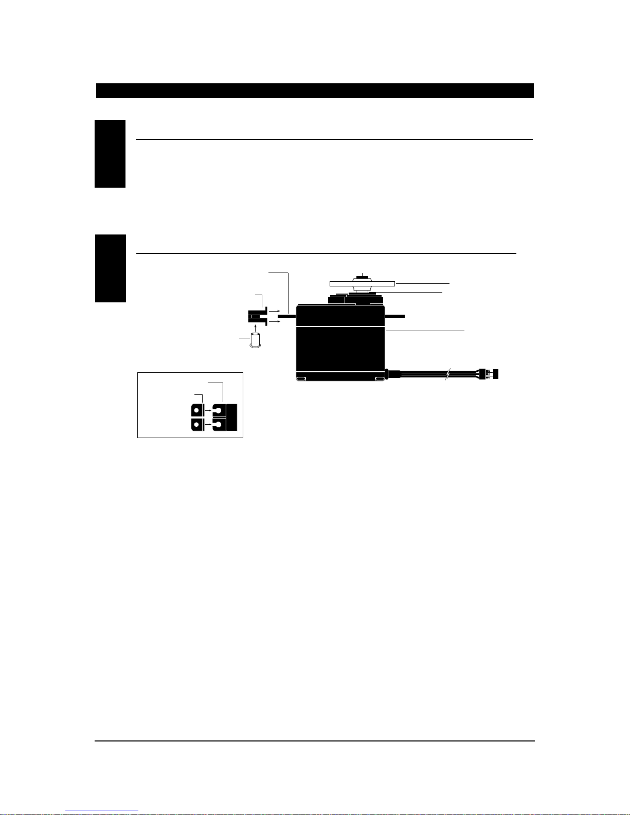
SERVO LAYOUT
2.4
Servo Mounting Flange
Rubber Grommets
Rubber Grommets
Servo Case
Servo Lead w/Connector
Servo Output Shaft
Servo Mounting Flange
Servo Arm/Horn
Servo Arm Retaining Screw
Servo Eyelet
Top View
Page 11
CHAPTER 3:SPECIFICATIONS • Introduction
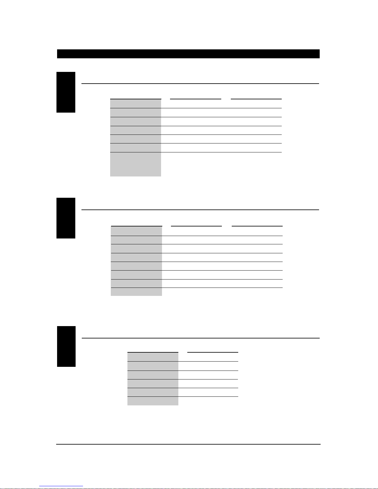
SYSTEM SPECIFICA TIONS
TRANSMITTER SPECIFICA TIONS
3.1
3.2
SYSTEM NAME XP652A XP652H
TRANSMITTER BODY NET-E136U NET-E136U
RECEIVER R600 R600
CHARGER NEC-221 NEC-222
AIRBORNE BATTERY 4N-600 4N-1000
SERVOS NES-517BBX4 NES-517BBX5
ACCESSORIES Mini Switch Mini Switch
12" Aileron Extension 12" Aileron Extension
Servo Accessories Servo Accessories
Instruction Manual Instruction Manual
TYPE AIRPLANE HELI COPTER
MODEL NUMBER NET-E136U NET-E136U
ENCODER 6 Channel Computer System 6 Channel Computer System
RF 50/53/72 MHz 50/53/72MHz
MODULATION PPM (FM), PCM (S,Z) PPM (FM), PCM (S,Z)
OUTPUT POWER Approximately 1 Watt Approximately 1 Watt
CURRENT DRAIN 200mA 200mA
POWER SOURCE 1.2Vx8 Nicad (9.6V) 600mah 1.2Vx8 Nicad (9.6V) 600mah
OUTPUT PULSE 1000-2000 (1500 Neutral) 1000-2000 (1500 Neutral)
TYPE AIRPLANE HELI COPTER
11
XP652 MANUAL Introduction
SERVO SPECIFICA TIONS3.3
TORQUE (oz./in.) 40.3
SPEED .25
WEIGHT 1.47
SIZE (in.) (W x L x H) 0.73 x 1.52 x 1.32
BB YES
MOTOR 3-Pole Ferite
TYPE 517BB
Page 12

RECEIVER SPECIFICA TIONS
3.4
CHARGER SPECIFICA TIONS
AIRBORNE BA TTERY P ACK
3.5
3.6
MODEL NUMBER NER-600
TYPE 6-Channel/FM-ABC & W/Circuitry
FREQUENCY 50/53/72MHz
SENSITIVITY (Microseconds) 5µs Minimum
SELECTIVITY 8KHz/50dB
WEIGHT (oz.) 1 oz.
SIZE (in.) (W x L x H) 1.43 x 2.06 x .55
RECEIVER ANTENNA 39" For All Aircraft Frequencies
TYPE R600 FM
MODEL NUMBER
INPUT VOLTAGE
OUTPUT CURRENT
CHARGING TIME
NEC-211
AC 100-120V
50mAh Tx/50mAh Rx
15 Hours
NEC-222
AC 100-120V
50mAh Tx/150mAhRx
15 Hours
TYPE AIRPLANE HELICOPTER
MODEL NUMBER
VOLTAGE
SIZE (in.) (W x L xH)
WEIGHT (oz.)
4N-600
4.8V
2.24 x 0.59 x 2.05
3.3
4N-1000
4.8V
2.60 x 0.63 x 1.70
4.9
TYPE AIRPLANE HELICOPTER
CHAPTER 3:SPECIFICATIONS • Introduction continued
12
XP652 MANUAL Introduction
Page 13
CHAPTER 4:BATTER Y CHARGING • Introduction
The pilot lamps should always be on during the
charging operation. If they are not, check to make
sure you have turned off both the transmitter and
receiver.
Do not use the charger for equipment other than JR.
The charging plug polarity may not be the same and
equipment damage may result.
Do not use other manufacturers’ after-market
accessories that plug into the transmitter’s charging
jack. If you do, any damage that results will not be
covered by warranty. If you are unsure of
compatibilities with your radio, seek expert advice
before doing anything to avoid possible damage.
During the charging operation, the charger’s
temperature is slightly elevated. This is normal.
CHARGER4.2
It is imperative that you fully charge both the
transmitter and the receiver battery packs prior to
each day of flying. For the initial charge, leave the
charger and batteries hooked up for 20-24 hours in
order to fully charge both battery packs to peak
capacity. For subsequent charges, leave the charger and
batteries hooked up overnight (approximately 16
hours).
The charger supplied with this system is designed to
recharge your transmitter battery at a rate of 50mA. The
receiver battery pack will charge at 50mA for the
600mAh airplane battery pack and at 150mA for the
1000mAh helicopter battery pack.
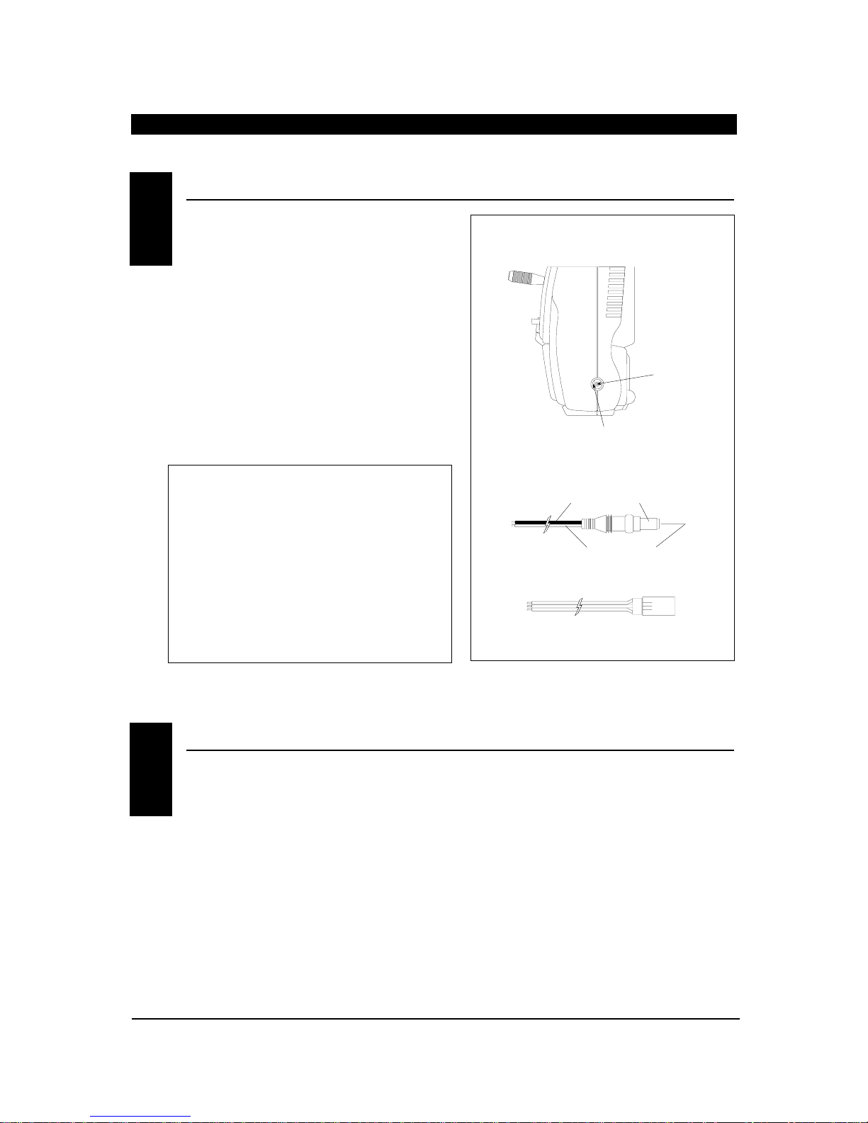
Transmitter Only
The center pin on all JR remote control systems is
negative. Therefore, the center pin on all JR
chargers is negative, not positive. This is different
from any other manufacturers’ chargers and radio
systems. Beware of improper connections based on
“color code” wire leads as they DO NOT APPLY in
this instance. You must make certain that the
center pin of your JR transmitter is always
connected to the negative voltage for correct
polarity hookup.
TRANSMITTER/RECEIVER4.1
13
XP652 MANUAL Introduction
RIGHT SIDE OF TRANSMITTER
CENTER
PIN IS
NEGATIVE
OUTSIDE IS POSITIVE
CHARGER PIGTAIL FOR TRANSMITTER
BLACK TO POSITIVE
RED TO NEGATIVE
CHARGER PIGTAIL FOR RECEIVER
RED–POSITIVE / BROWN–NEGATIVE / ORANGE–SIGNAL
Page 14
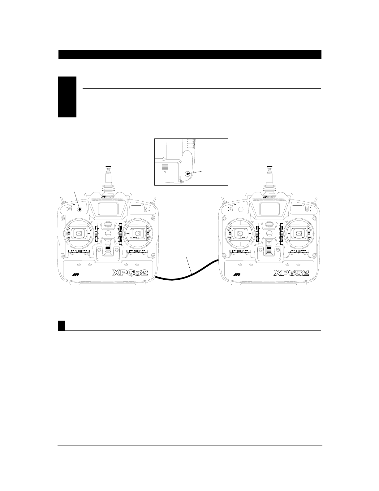
The XP652 features a built-in trainer system. The
transmitter can be used as either a master (trainer)
or as a slave (trainee). The XP652 is compatible
with all other current JR radios that have built-in
trainer systems. An optional trainer cord is needed
(JRPA130).
1. Match the servo reversing and trims of both radios.
2. Plug the optional trainer cord into both
transmitters.
3. Turn on the master transmitter. (Note: The slave
radio must be left off.)
4. Test all the control functions on your aircraft with
the master radio.
5. Push the trainer button on the master transmitter
and check all the control functions with the slave
radio.
CHAPTER 5:TRAINER SYSTEM • Introduction
TRAINER SYSTEM5
D.S.C.
TRAINER
CORD INPUT
Operating the T rainer System
14
XP652 MANUAL Introduction
TRAINER
BUTTON
MULTI
FLIGHT MODE
DATA
GEAR / MIX
0
1
FUNCTION 3-4 1-4 FUNCTION 1-2 2-3
DISPLAY
TRAINERELEVATOR D/R
ENTER CLEAR
MODE CHANNEL INCREASE DECREASE
6 CHANNEL MULTI-DATA DISPLAY SYSTEM
MASTER TX
POWER SWITCH ON
ON
XF622
VOLTAGE
INDICATOR
THROTTLE HOLD
FLAP / MIX
NET-E126
0
1
AILERON D/R
-
HE/AC
HELICOPTER AIRPLANE
+
OPTIONAL
TRAINER CORD
(JRPA130)
MULTI
FLIGHT MODE
DATA
GEAR / MIX
0
1
FUNCTION 3-4 1-4 FUNCTION 1-2 2-3
DISPLAY
TRAINERELEVATOR D/R
ENTER CLEAR
MODE CHANNEL INCREASE DECREASE
6 CHANNEL MULTI-DATA DISPLAY SYSTEM
SLAVE TX
POWER SWITCH OFF
ON
XF622
VOLTAGE
INDICATOR
+
THROTTLE HOLD
FLAP / MIX
HE/AC
HELICOPTER AIRPLANE
NET-E126
-
AILERON D/R
0
1
Page 15
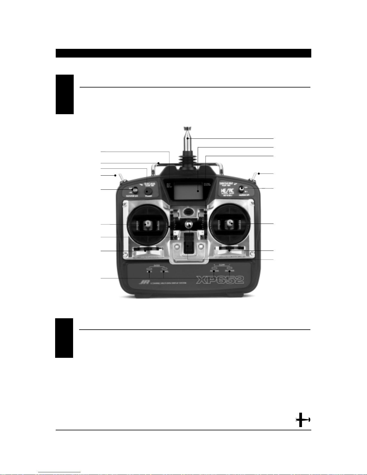
1. THRO Throttle Channel
2. AILE Aileron Channel
3. ELEV Elevator Channel
4. RUDD Rudder Channel
5. GEAR Gear Channel
6. AUX 1 Auxiliary 1 Channel (Flap)
Transmitter Throttle ALT
The throttle ALT function makes the throttle stick trim
active only when the throttle stick is less than half
throttle. This gives easy, accurate idle adjustments
without affecting the high throttle position.
RECEIVER CHANNEL ASSIGNMENT/TRANSMITTER THROTTLE AL T1.2
AUX 1/FLAP MIXING
AILERON DUAL RATE
ANTENNA
LCD SCREEN
GEAR SWITCH
ELEVATOR DUAL RATE
TRAINER BUTTON
AILERON/ELEVATOR STICK
THROTTLE/RUDDER STICK
POWER SWITCH
AILERON TRIM
ELEVATOR TRIM
THROTTLE TRIM
RUDDER TRIM
NECK STRAP EYELET
INPUT KEYS
CARRYING HANDLE
CONTROL IDENTIFICA TION AND LOCA TION• Mode II
CHAPTER 1:TRANSMITTER CONTROLS • Airplane
1.1
15
XP652 MANUAL Airplane
Page 16
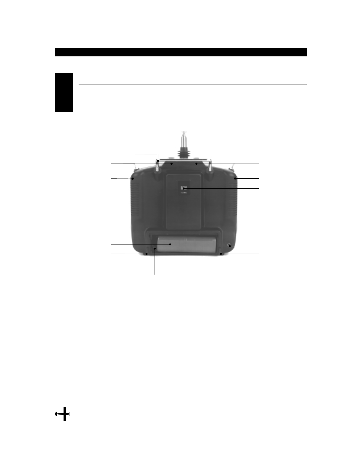
TRANSMITTER REAR1.3
16
XP652 MANUAL Airplane
Note: Your transmitter has a 5-year lithium battery
to protect your pre-programmed data against main
transmitter battery failure. If your system reads 0.0
volts, or has an unfamiliar display (service mode) or
your data resets to the factory defaults, return your
transmitter to Horizon Service Center (see page 91)
for lithium battery replacement.
BATTERYCONNECTOR
Use caution when disconnecting/removing the
transmitter battery pack as if the connector is not
properly disconnected, damage to the connector
and/or the radio system can result.
CARRYING HANDLE
TRANSMITTER
CASE SCREW
TRANSMITTER
CASE SCREW
BATTERY
TRANSMITTER
CASE SCREW
TRANSMITTER
CASE SCREW
TRANSMITTER
CASE SCREW
CRYSTAL
TRAINER JACK
TRANSMITTER
CASE SCREW
Page 17
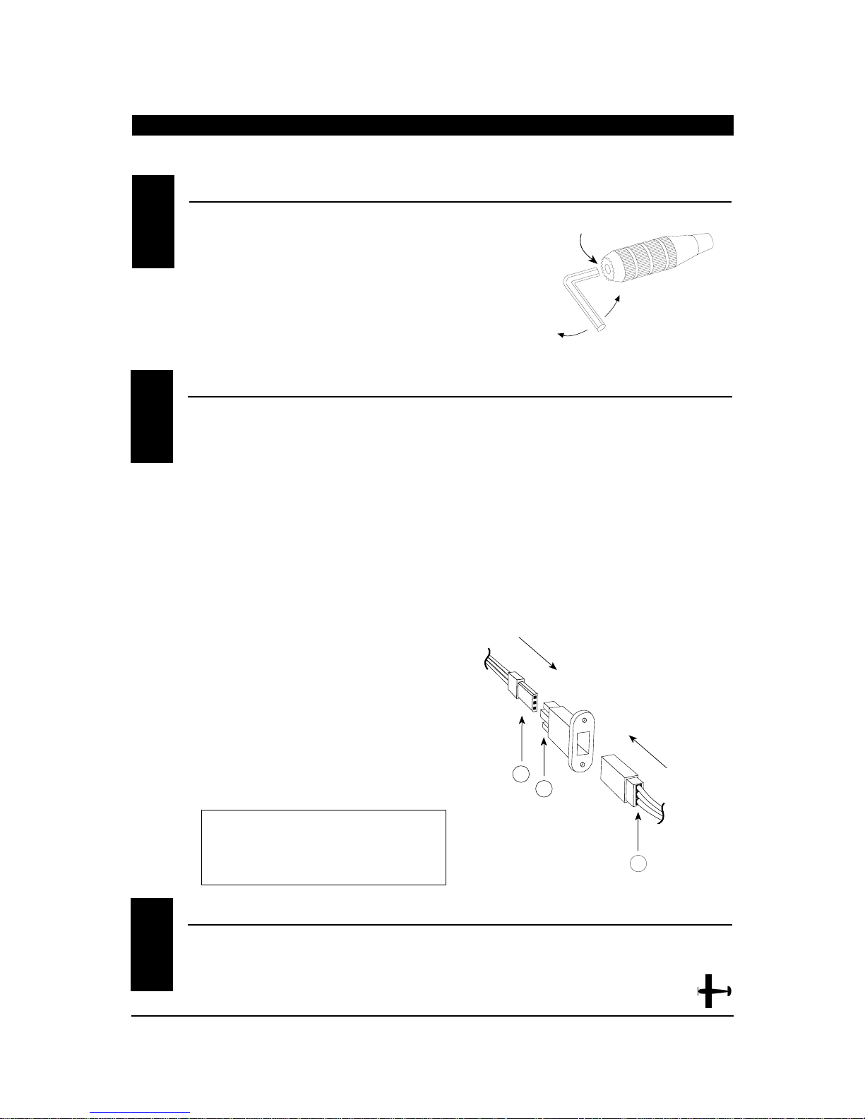
CHAPTER 1:TRANSMITTER CONTROLS • Airplane continued
To adjust the control stick length, use a 2mm Allen
wrench to unlock the set screw located inside the end
of the control stick. Turn the set screw counterclockwise
to loosen it, then turn the knurled portion of the stick
to adjust the length. Counterclockwise will lengthen the
stick and clockwise will shorten it. After the control stick(s)
has been adjusted to suit your flying style, tighten the set
screw.
For proper DSC hook-up and operation:
1. Leave the transmitter power switch off. The
transmitter will not transmit any radio
frequency (RF) in this position.
2. Plug the optional DSC cord (JRPA132) into the
DSC port in the rear of the transmitter.
3. The encoder section of the transmitter will now
be operational and the LCD display will be lit.
4. Plug the other end of the DSC cord into the
receiver charge receptacle. Turn on the switch
harness.
Note: When installing the optional charging
jack (JRPA024) be sure to hook the charging jack
receptacle securely into the switch harness
charge cord.
Why you should use the DSC function:
1. The DSC enables you to check the control
surfaces of your airplane without drawing the
fully operational 200mAh from your transmitter
battery pack. Instead, you will only draw 70mAh
when using the DSC function.
Note: You will need to purchase (separately)
both the DSC cord (JRPA132) and the JR Deluxe
Switch Harness (JRPA001) to make use of the
XP652 DSC function.
2. The DSC function allows you to make final
adjustments to your airplane or helicopter
without transmitting any radio signals.
Therefore, if another pilot is flying on your
frequency, you can still adjust your aircraft and
not interfere with the other aircraft.
Note: Under no circumstances should you
attempt to fly your aircraft with the DSC cord
plugged in! This feature is for bench checking
your aircraft only.
There is an eye hook on the front of the transmitter
for attaching an optional neck strap (JRPA023). The
eye hook is precisely positioned (see Section 1.1)
so that the transmitter will be perfectly balanced when
a neck strap is used.
CONTROL STICK LENGTH ADJUSTMENT1.4
DIRECT SERVO CONTROL (DSC)1.5
A
B
C
A - Charge Cord/DSC Receptacle
B - Switch Harness Lead
C - Charger/DCS Cord
NECK STRAP A TT ACHMENT1.6
17
XP652 MANUAL Airplane
SET SCREW
LOOSEN
TIGHTEN
Page 18
18
XP652 MANUAL Airplane
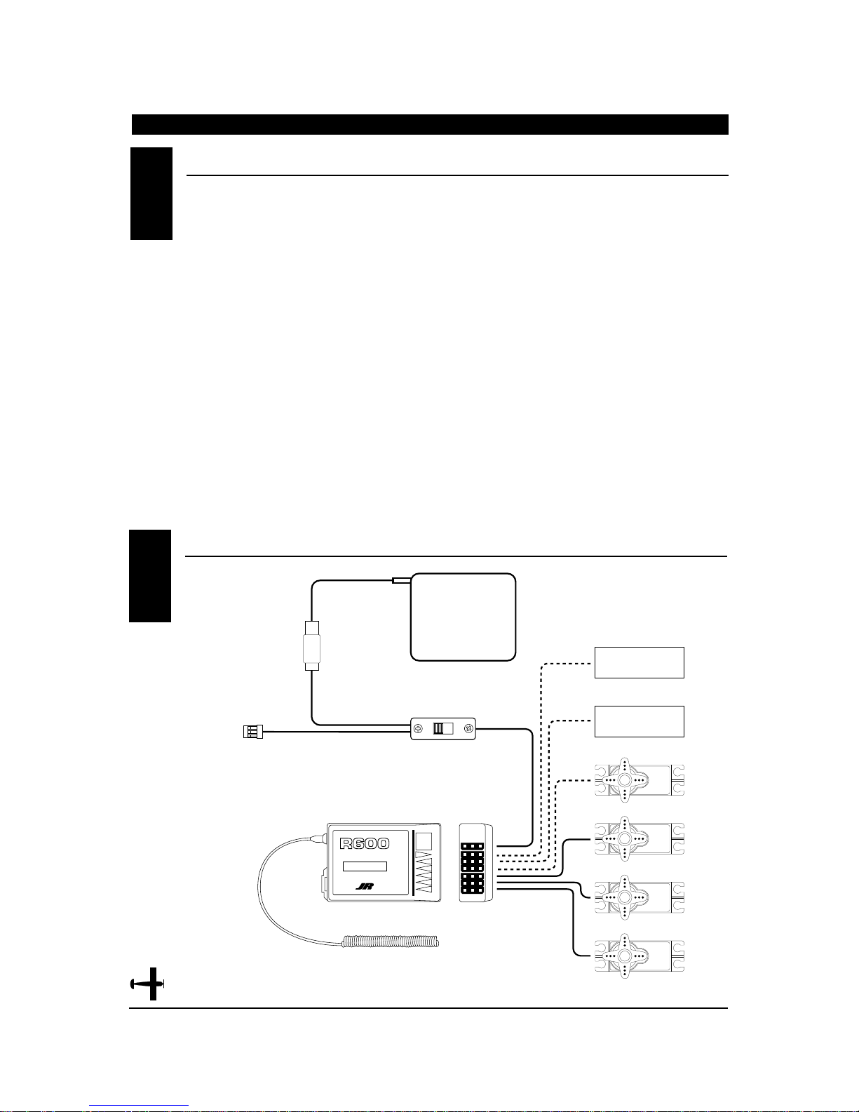
It is important to correctly install the radio system
in your model. Please read and carefully follow the
suggestions listed below.
1. For added protection, wrap the Rx and the Rx
Nicad in foam rubber that is at least 1/4” thick.
2. Run the Rx antenna through the fuselage and make
sure it is fully extended. Never cut or bundle your
Rx antenna — this will decrease range and
performance.
3. Rubber servo grommets are included with your
radio system and should be installed in the servo
flanges. The servos should then be mounted on
either hardwood rails or a plywood tray with the
mounting screws provided. Do not overtighten the
mounting screws. The flange of the brass eyelets
should face down (toward the wood).
4. All servos must be able to move freely over the full
range of their travel. Make sure the linkages do not
impede servo travel. A stalled servo will drain the
battery pack within a few minutes.
5. Before installing servo output arms, make sure the
servo is in its neutral position.
6. In the case of gas-powered model aircraft, mount
the receiver power switch on the side of the
fuselage opposite the muffler to protect the switch
from exhaust residue. With other types of models,
mount the switch in the most convenient place.
Make sure that the switch operates freely and is
capable of traveling its full distance.
7. With your model sitting on the ground and the
transmitter antenna collapsed, check that your
system works at a distance of 75 to 100 feet.
If your system stops functioning at a distance that
is shorter than listed above, please contact the
Horizon Service Center for further information prior
to flying your model.
INST ALLA TION REQUIREMENTS
CHAPTER 2:CONNECTIONS • Airplane
CONNECTIONS2.2
2.1
BATT
AUX 1
GEAR
RUDD
ELEV
AILE
THRO
6 CH 72MHz FM RECEIVER
ABC&W INTERFERENCE
PROTECTION SYSTEM
R600 RECEIVER
RECEIVER BATTERY
4N-600
AUXILIARY 1 (FLAP)
OFF
ON
ON/OFF SWITCH HARNESS
(JRPA003)
NEW ABC & W SYSTEM
6 CHANNEL RECEIVER
NER-226X
JAPAN REMOTE CONTROL CO., LTD
BATT
AUX 1
GEAR
72MHz
RUDD
ELEV
AILE
THRO
MADE IN JAPAN
226X RECEIVER
ANTENNA
GEAR
RUDDER
ELEVATOR
AILERON
THROTTLE
Page 19
CHAPTER 4:BATTER Y ALARM AND DISPLA Y • Airplane
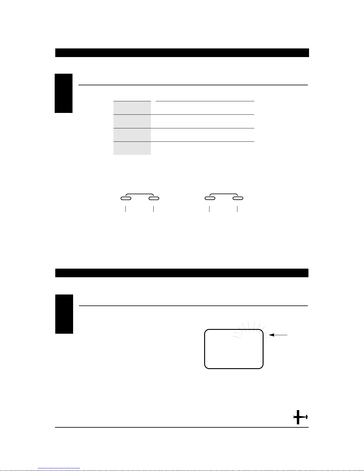
BUTTON USE
MODE Used to move up through the available functions
CHANNEL Used to select the desired channel
INCREASE Used to increase the value of the selected function
DECREASE Used to decrease the value of the selected function
CHAPTER 3:KEY INPUT AND DISPLAY • Airplane
KEY INPUT AND DISPLA Y3
When the transmitter battery drops below 9.0 volts,
the display will start to flash BAT and an audible alarm
will sound for 8 beeps. These warnings mean you
should land your aircraft immediately.
Note: During the period that the battery alarm is
flashing, the input buttons will not function. If you are
currently in the function mode, the transmitter will exit
automatically and return to the normal display
(see Section 5.1).
BA TTERY ALARM AND DISPLAY4
BAT
8.9V
FLASHING
MODE
ENTER
CHANNEL
To enter the function mode press the
MODE and CHANNEL buttons
simultaneously while the transmitter is on.
Press the INCREASE and DECREASE
buttons simultaneously to clear the
screen or return to factory preset.
To enter the system mode press the
MODE and CHANNEL buttons
simulataneously and hold while
turning on the transmitter.
INCREASE
CLEAR
+–
DECREASE
19
XP652 MANUAL Airplane
V
Page 20
20
XP652 MANUAL Airplane
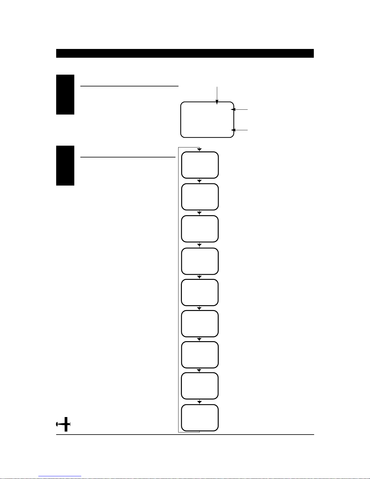
When the power switch is turned on the screen
will read as shown here in the diagram. This
screen is referred to as the normal display.
To enter the system mode, press the MODE
and CHANNEL buttons simultaneously while
you turn on the transmitter. You can now
select any of 7 system mode functions shown
here in the flow chart. To exit the system mode,
press the MODE and CHANNEL buttons
simultaneously or turn off the transmitter. Press
the mode button to move through the system
mode functions. Information for each function is
located on the page number listed next to the
function name.
SYSTEM MODE
CHAPTER 5:INPUT MODE AND FUNCTION • Airplane
5.2
I0.4V
AC I
MODEL NUMBER
AC = FIXED WING AIRCRAFT
HE = HELICOPTER
BATTERY VOLTAGE
NORMAL DISPLA Y5.1
I
MD
L
I
-
I
PP
M
C
L
FSM
AC
TYP
AC
RST
E.A
SW
D/R
OF
WNG
MIX
MODEL TYPE SELECTION Page 22
DATARESET Page 23
DUAL RATE
SWITCH SELECTION Page 24
Page 25
WING TYPE
SELECTION
FPR FLAPERON
MODEL SELECTION Page 27
MODEL NAME ENTRY Page 28
MODULATION SELECTION Page 29
FAIL-SAFE
(Z-PCM MODE ONLY) Page 30
FAILSAFE MEMORY
(S-PCM MODE ONLY) Page 32
V
OF
FSI
Page 21
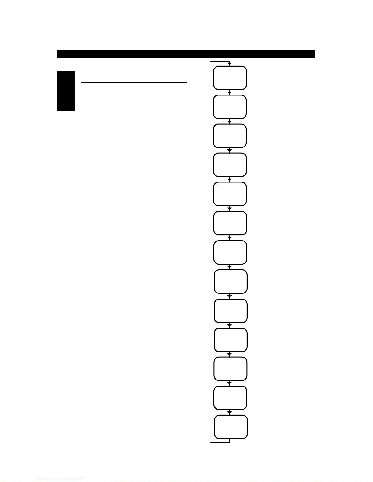
To enter the function mode, turn on the
transmitter. Press the MODE and CHANNEL
buttons simultaneously until a beep is heard. The
display will change accordingly and show the last
active function. Press the MODE button to scroll down
through the functions one by one as shown in the
flowchart below. Once the appropriate function is
selected, use the CHANNEL button to select the
appropriate channel. Use the INCREASE and
DECREASE buttons to adjust the values displayed on
the screen.
CHAPTER 5:INPUT MODE AND FUNCTION • Airplane continued
FUNCTION MODE5.3
THR
-
REV•NORM
SERVO REVERSING Page 34
DUAL RATE Page 35
EXPONENTIAL Page 36
SUB-TRIM Page 37
TRAVELADJUSTMENT Page 38
AILERON TO
RUDDER MIXING Page 39
ELEVATOR TO FLAPMIXING
Page 41
DIFFERENTIAL Page 43
(will only appear if flaperons or
Delta wing types have been
activated)
FLAP TO ELEVATOR
OFFSET TRIM Page 44
PROGRAMMABLE MIXING A
Page 45
PROGRAMMABLE MIXING B
Page 45
PROGRAMMABLE MIXING C
Page 45
TRIM OFFSET MEMORY
Page 48
I00
%
AIO
D/R
0
%
AIO
EXP
+I00
%
TRV ADJ
A--R
MIX
0
0
%
E--F
MIX
0
%
DIF
MIX
0
%
F-E
OFFSET
0
AII
MIX
0
%
BII
MIX
0
%
CII
MIX
0
%
TRM
OFFSET
0
%
SB-TRIM
21
XP652 MANUAL Airplane
Page 22
22
XP652 MANUAL Airplane
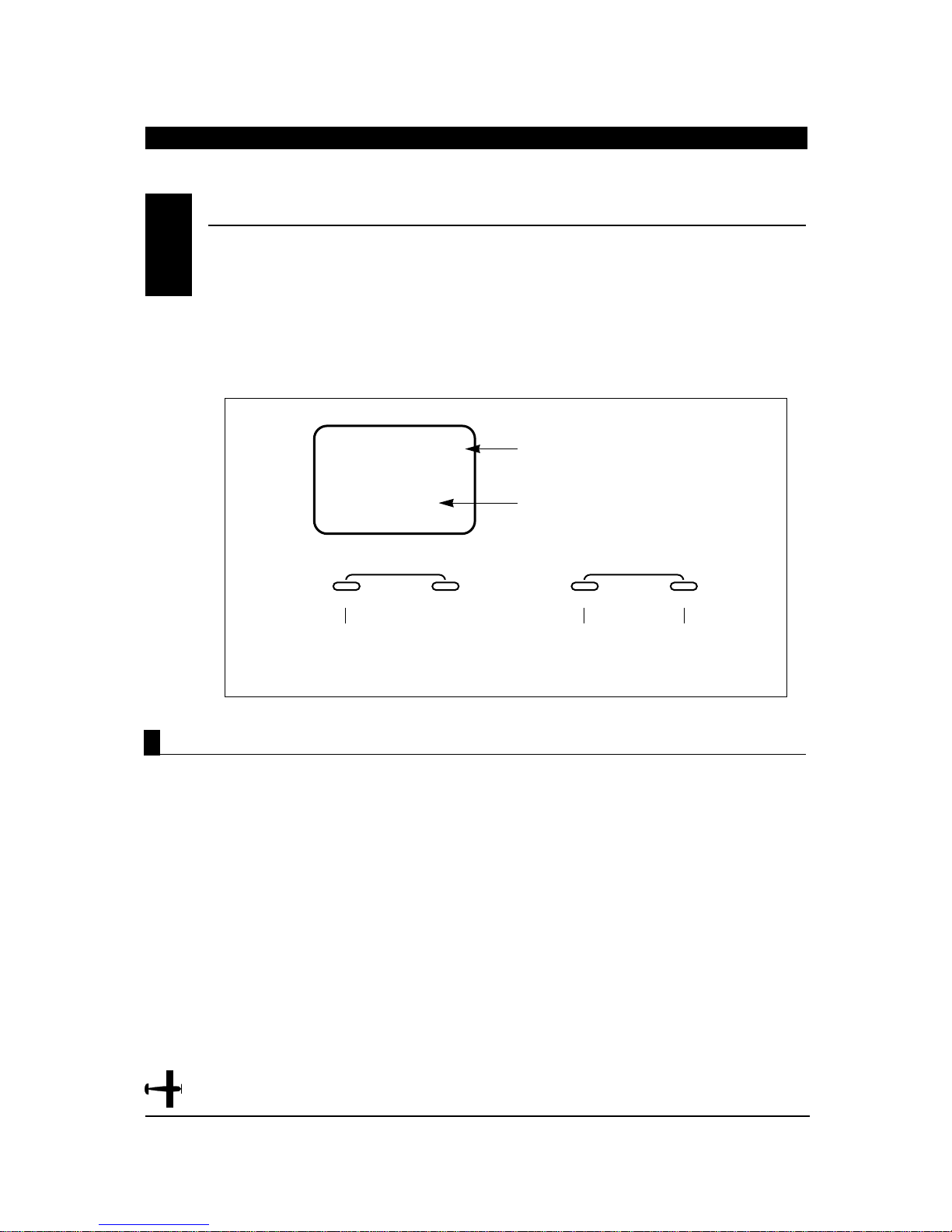
Two types of aircraft programming are available
with the XP652, airplane (AC) and helicopter (HE).
When you enter the model type selection function,
the current model type will appear on the screen.
(The current model type being the factory preset or the
last model used.) When you press the increase or
decrease button to change the model type, the new
model type indicated on the screen will flash. For
example, if the current model type is AC and you
change to HE, HE will flash on the screen. The flashing
alerts you to the change of model type and will stop
once you move to the next function or exit the system
mode.
1. Press the MODE and CHANNEL buttons
simultaneously and hold.
2. Turn on the transmitter to enter the system mode.
3. Press the MODE button until TYP appears on the
screen.
4. Press the INCREASE or DECREASE button until
the desired model type appears on the screen
(AC = airplane HE = helicopter).
5. Press the MODE button to access the data reset
function.
6. To exit, press the MODE and CHANNEL buttons
simultaneously.
Accessing the Model T ype Selection Function
MODEL TYPE SELECTION• System Mode
CHAPTER 6:FUNCTIONS • Airplane (System Mode)
6.1
(AC or HE)
TYP
AC
ENTER
MODE
Press the MODE button
until TYP appears on
the screen.
CHANNEL INCREASE
INDICATES MODEL TYPE
SELECTION FUNCTION
MODEL TYPE
AC = AIRPLANE
HE = HELICOPTER
CLEAR
+
Press the INCREASE or DECREASE
button until the desired model type
appears on the screen.
–
DECREASE
Page 23
–
+
MODE
ENTER
CHANNEL INCREASE
CLEAR
DECREASE
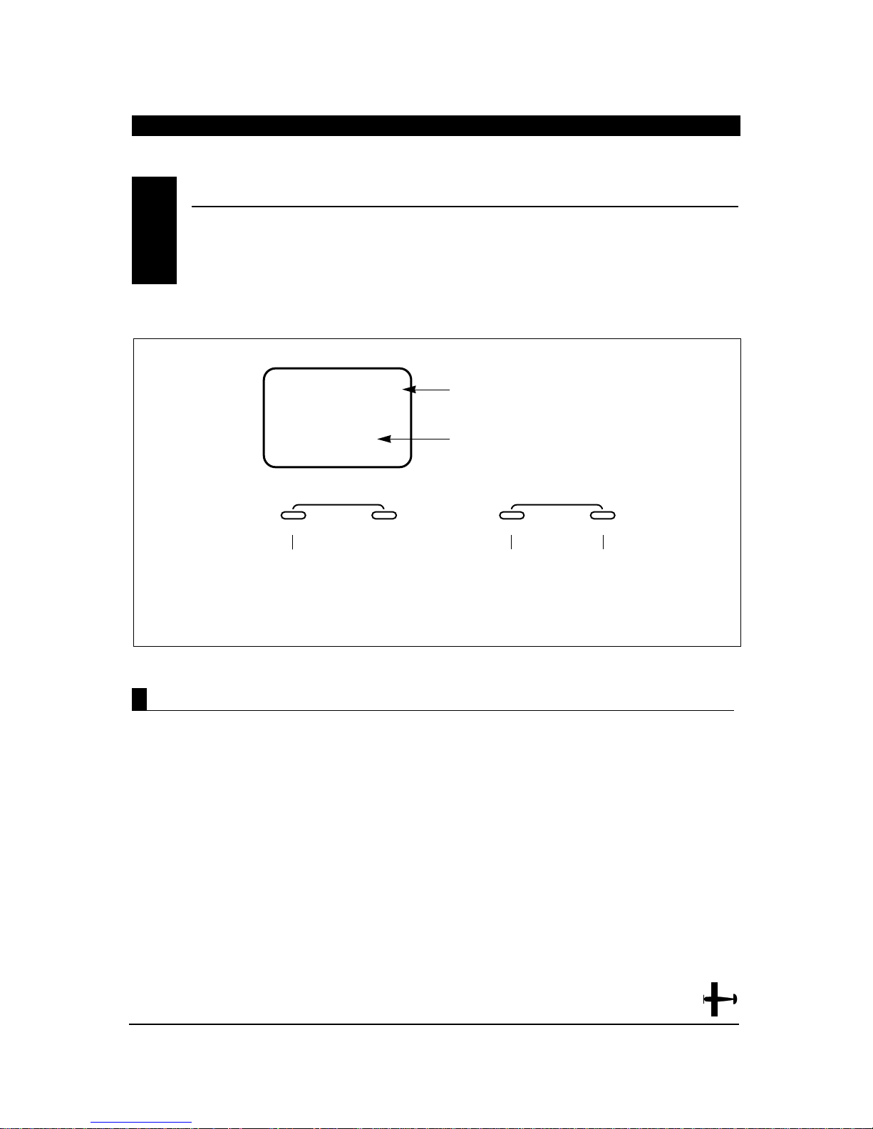
Press the INCREASE and
DECREASE buttons simultaneously
to reset the data (a beep will sound).
Press the MODE button
until RST appears on
the screen.
AC
RST
INDICATES DATA RESET FUNCTION
MODEL TYPE TO RESET
Accessing the Data Reset Function
CHAPTER 6:FUNCTIONS • Airplane continued
The data reset function allows you to reset all the
programming in the selected model (1-5) to the
factory settings. Before using the data reset
function it is important to enter the model
selection function and check that the current model
number (1-5) indicated is the model that you want to
reprogram to the factory settings. The model selection
function is described in Section 6.5.
1. Press the MODE and CHANNEL buttons
simultaneously and hold.
2. Turn on the transmitter to enter the
system mode.
3. Press the MODE button until RST appears on the
screen.
4. Press the INCREASE and DECREASE buttons
simultaneously to reset the data. (To confirm that
the selected model's programming has been reset,
a beep will sound and the AC or HE will
momentarily disappear from the screen.)
5. Press the MODE button to access the dual rate
switch selection function.
6. To exit, press the MODE and CHANNEL buttons
simultaneously.
DA T A RESET• System Mode
6.2
23
XP652 MANUAL Airplane
Page 24
24
XP652 MANUAL Airplane
CHAPTER 6:FUNCTIONS • Airplane continued
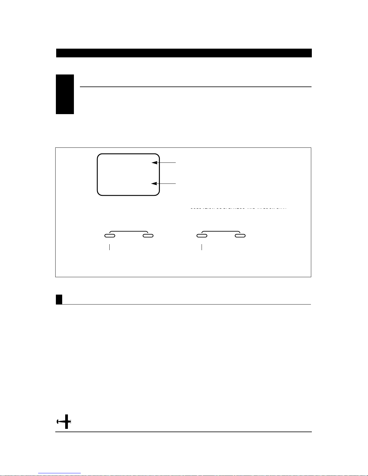
The dual rate switch position is selectable and the
elevator and aileron dual rates can be combined on
one switch. This allows a single switch to be used
when moving from high rates for wild maneuvers to
low rates for mild maneuvers. Exponential Rate
(EXP) is also available for both aileron and elevator
and works in conjunction with the dual rate function to
provide mild control movements around neutral while
allowing maximum servo travel. This reduces
sensitivity in the middle portion of the stick control
and still allows full travel at the end of the stick
control. Refer to section 7.3 for exponential rate
adjustment.
1. Press the MODE and CHANNEL buttons
simultaneously and hold.
2. Turn on the transmitter to enter the system mode.
3. Press the MODE button until D/R SW appears on
the screen.
4. Press the INCREASE button until the desired
switch position appears on the screen.
5. Press the MODE button to access the wing type
selection function.
6. To exit, press the MODE and CHANNEL buttons
simultaneously.
Accessing the Dual Rate Switch Selection Function
DUAL RA TE SWITCH SELECTION• System Mode
6.3
COMBINED FUNCTION OPERATION OF ELEVATOR
AND AILERON DUALRATE ON GEAR/MIX SWITCH
D/R
SW
E.A
ENTER
MODE
Press the MODE button
until D/R SW appears
on the screen.
CHANNEL INCREASE
INDICATES DUAL RATE SWITCH FUNCTION
INDICATES SWITCH POSITION
E.A = ELEVATOR AND AILERON OPERATE INDIVIDUALLY
A. = OPERATION OF ELEVATOR AND AILERON DUAL
RATE ON AILERON DUAL RATE SWITCH
E. = OPERATION OF ELEVATOR AND AILERON DUAL
RATE ON ELEVATOR DUAL RATE SWITCH
CF = OPERATION OF ELEVATOR AND AILERON DUAL
RATE ON FLIGHT MODE SWITCH
CLEAR
Press the INCREASE button
until the desired switch position
appears on the screen.
+
–
DECREASE
Page 25
Accessing the Wing T ype Selection Function
Flaperon, V-tail and Delta mixing are available for
specialty aircraft that require those functions. The
flaperon feature mixes flaps with ailerons so the
ailerons can be drooped for takeoffs and landings
while still functioning fully as ailerons. V-tail mixing
combines rudder and elevator for V-tail operations. The
Delta wing function allows the aileron to also act as the
elevator, while retaining independent use of both
functions. The Delta wing function allows the ailerons
to also act as the elevator, while retaining independent
use of both functions.
Flaperon Setup
When using flaperon mixing, two servos (one for each
aileron) must be used. Connect the left aileron servo to
channel #6 (Aux 1) and the right aileron servo to
channel #2 (Aile) in the receiver. Individual functions
(e.g., servo reversing, sub-trims, etc.) are still available
for each of the channels. Use sub-trims for individual
neutral adjustment. Adjust the aileron travel values by
increasing or decreasing the aileron dual rate. Flap
adjustments are made with flap left/right travel
adjustment described in Section 7.5. Also see aileron
differential in Section 6.18.
V-Tail
V-Tail mixing requires two servos. Connect the left tail
servo to channel #3 (Elev) and the right tail servo to
channel #4 (Rudd) in the receiver. Individual functions
(e.g., servo reversing, sub-trims, etc.) are available for
each servo. Use sub-trims for individual neutral
adjustments described in Section 7.4. V-Tail elevator
travel is adjusted by elevator dual rates described in
Section 7.2.
Delta Wing Mixing
Delta, or Elevon mixing as it is commonly known, is the
final wing mixing selection in your XP652. This style of
aircraft also employs two wing servos. However, in
essence, there is not an elevator present. Instead, at an
elevator stick input, the two wing servos function in
conjunction with one another in the same direction to
create an up/down movement of the aircraft. Also,
when an aileron control is given, the two wing servos
move in opposite directions to function as ailerons as
well.
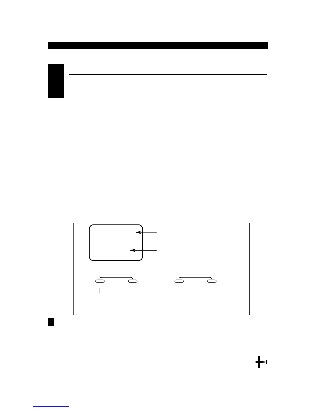
1. Press the MODE and CHANNEL buttons
simultaneously and hold.
2. Turn on the transmitter to enter the system mode.
3. Press the MODE button until the MIX WNG appears
on the screen.
4. Press the channel button to select either the wing
type (WNG) or v-tail (VTL) mode.
5. Press the MODE button to access the Model
Selection Function.
6. To exit, press the MODE and CHANNEL buttons
simultaneously.
WING TYPE SELECTION• System Mode
6.4
DLT= DELTA
WNG = WING TYPE SELECTION
WNG
Wing Type (WNG)
, Delta (DLT), or
V-tail
V-tail
25
XP652 MANUAL Airplane
MIX
FPR
INDICATES WING TYPE FUNCTION
FPR = FLAPERON
VTL = V-TAIL
OF
ENTER
MODE
Press the MODE
button until MIX
FPR appears on
the screen.
CHANNEL INCREASE
Press the CHANNEL
button to select
flaperon (FPR) or
v-tail (VTL) mixing.
OF = OFF
ON = ON
CLEAR
+
Press the INCREASE or DECREASE
button to turn the flaperon (FPR) or
v-tail (VTL) mixing on or off.
–
DECREASE
Page 26
26
XP652 MANUAL Airplane
CHAPTER 6:FUNCTIONS • Airplane continued
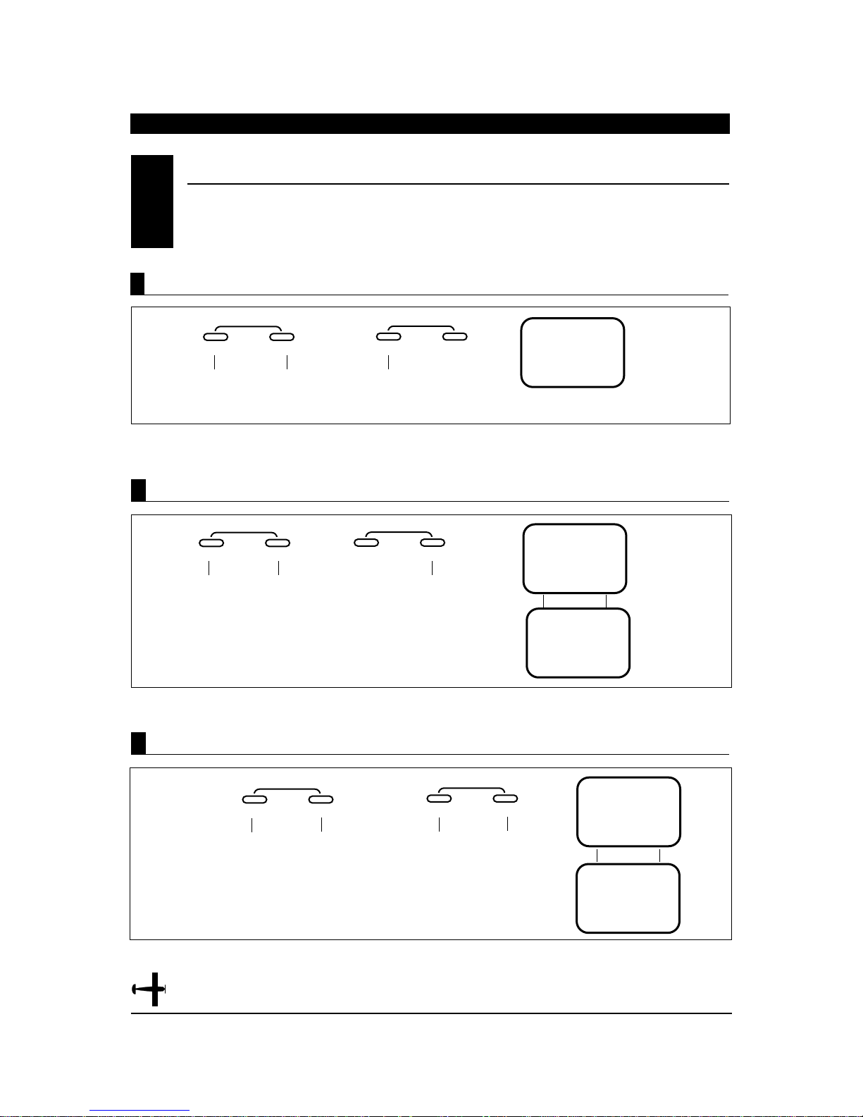
T o Activate Flaperon (FPR) Mixing (Wing Type Mode)
T o Activate Delta Wing (DLT) Mixing (Wing Type Mode)
MODE
ENTER
CHANNEL
Press the MODE and CHANNEL
buttons simultaneously to activate
and exit the system mode.
Press the
INCREASE
button to activate
Flaperon mixing.
OF
MIX
INCREASE
CLEAR
+–
DECREASE
OF = MIX OF
ON = MIX ON
MODE
ENTER
CHANNEL
Press the MODE and CHANNEL
buttons simultaneously to activate
and exit the system mode.
Press the
DECREÅSE button
to activate Delta
wing mixing.
OF
O
N
MIX
MIX
INCREASE
CLEAR
+–
DECREASE
MODE
ENTER
CHANNEL
Press the CHANNEL
button once to access
the V-tail mixing screen.
Next press either the
+ or - buttons once to
activate V-tail mixing.
DELTAWING
MIX ON
OF
OF
MIX
MIX
Press the MODEL and
CHANNEL buttons
simultaneously to activate
and exit the system mode.
INCREASE
CLEAR
+–
DECREASE
T o Activate V -Tail (VTL) Mixing
Note: It is also possible to activate both the flaperon (FPR)
and V-tail functions (VTL) to work simultaneously.
WING TYPE SELECTION• System Mode (continued)
6.4
Page 27
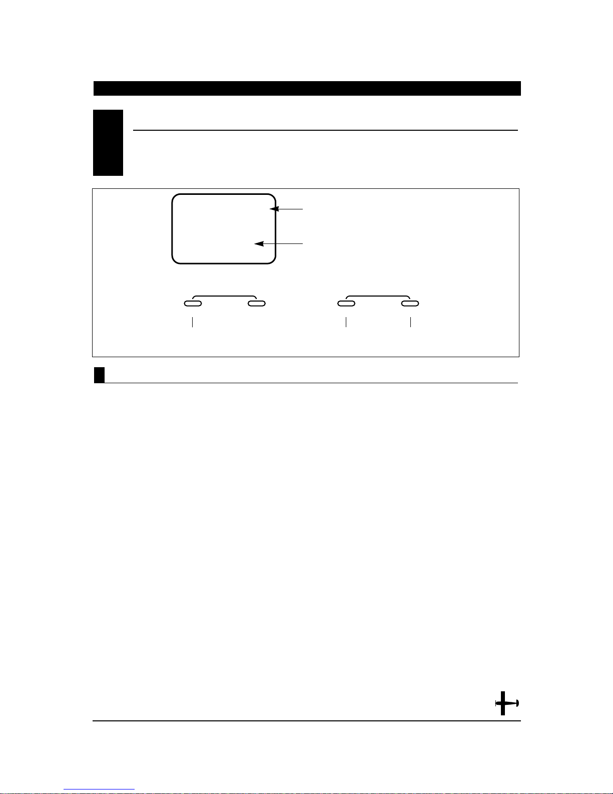
The XP652 has memory for five models. It can store
the settings for five airplanes, five helicopters or
three airplanes and two helicopters, ect.
1. Press the MODE and CHANNEL buttons
simultaneously and hold.
2. Turn on the transmitter to enter the
system mode.
3. Press the MODE button until MDL
appears on the screen.
4. Press the INCREASE or DECREASE button to
select model number 1 through 5.
5. Press the MODE button to access the model name
entry function.
6. To exit, press the MODE and CHANNEL buttons
simultaneously.
Accessing the Model Selection Function
MODEL SELECTION• System Mode
6.5
1 THOUGH 5
1 THROUGH 5
27
XP652 MANUAL Airplane
MDL
INDICATES MODEL SELECTION FUNCTION
I
ENTER
MODE
Press the MODE button
until MDL appears on
the screen.
CHANNEL INCREASE
MODEL NUMBER 1 OR 2
CLEAR
+
Press the INCREASE or DECREASE
button to select model number 1 or 2.
–
DECREASE
Page 28
28
XP652 MANUAL Airplane
CHAPTER 6:FUNCTIONS • Airplane continued
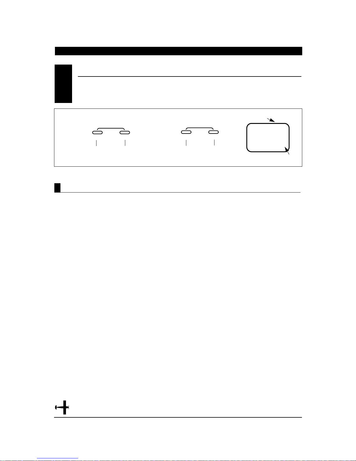
1. Press the MODE and CHANNEL buttons
simultaneously and hold.
2. Turn on the transmitter to enter the System Mode.
3. Press the MODE button until AC1 appears on the
screen.
4. Press the INCREASE or DECREASE buttons to
select the correct letter/number for the first
character (flashing).
5. To adjust the remaining 2 characters, press the
CHANNEL button until the desired character to be
adjusted is flashing.
6. Press the MODE button to access the modulation
select function.
7. To exit, press the MODEand CHANNEL buttons
simultaneously.
Accessing the Model Name Entry Function
MODE
ENTER
CHANNEL
Press the CHANNEL button
to select the character to be
changed (flashing).
Press the INCREASE or DECREASE
buttons to select the desired
character (A-Z, 1-9, etc.)
Flashing Character includes
character to be adjusted
CURRENT MODEL
NUMBER
I
ACI
Press the MODE button
until AC1 appears on the
screen.
INCREASE
CLEAR
+–
DECREASE
The XP652 allows a 3 digit name to be input for
each of the five (5) models available. The
current model will be displayed in the normal
display. This feature is useful to help identify
different aircraft types, or model setups.
MODEL NAME ENTRY• System Mode
6.6
Page 29
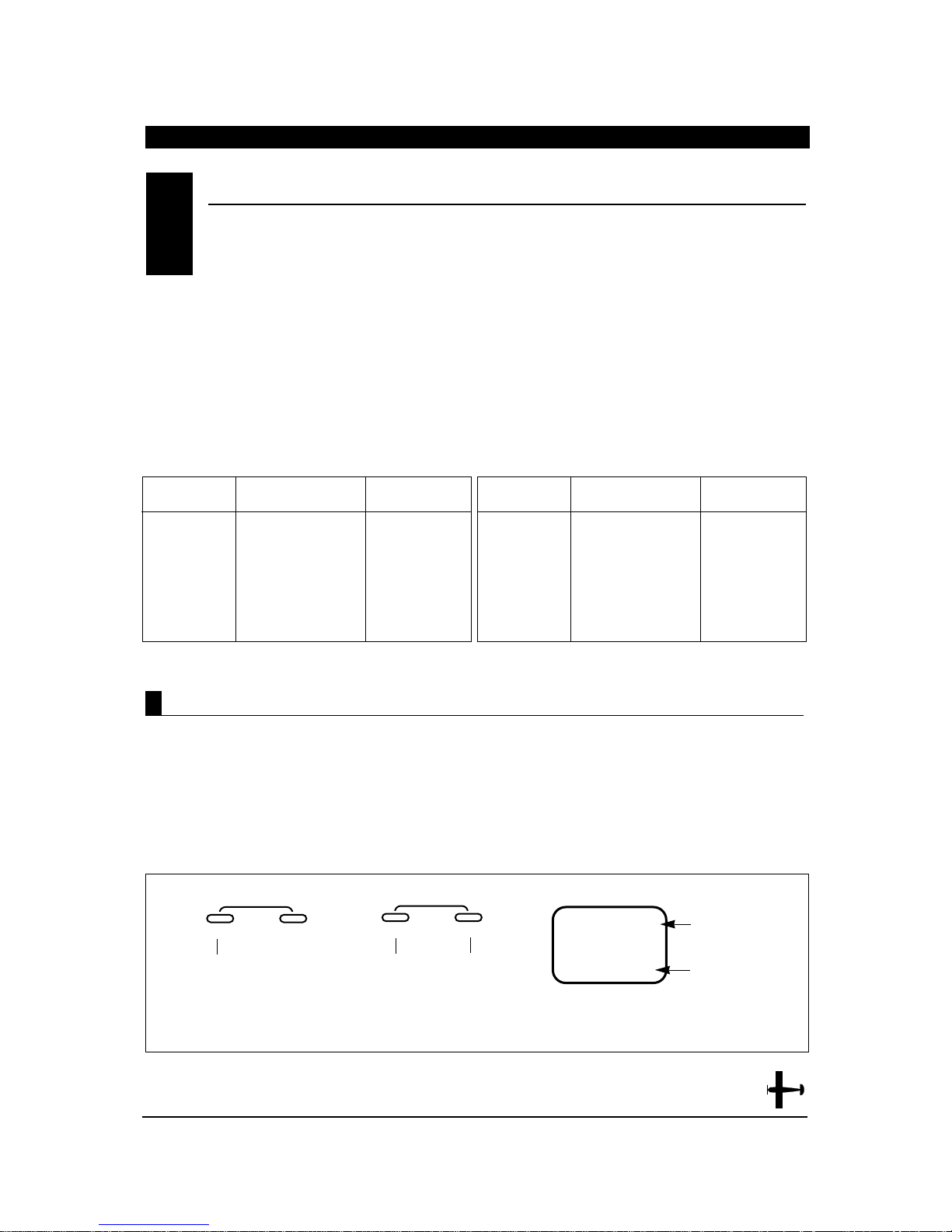
1. Press the MODE and CHANNEL buttons
simultaneously and hold.
2. Turn on the transmitter to enter the System Mode.
3. Press the MODE button until PPM appears on the
screen.
4. Press either the INCREASE or DECREASE buttons
to change the modulation to the desired setting
FM (PPM), Z-PCM (ZPC) or S-PCM (SPC).
5. Press the MODE button to access the Model Type
Function.
6. To exit, press the MODE and CHANNEL buttons
simultaneously.
Accessing the Modulation Select Function
MODE
ENTER
CHANNEL
Press the INCREASE or
DECREASE buttons to select
the desired modulation.
Note: The modulation for the current model in use can be viewed at a
glance by pressing the mode button with the system in the normal
screen position.
CURRENT
MODULATION TYPE
I
Press the MODE button
until PPM appears.
INCREASE
CLEAR
+–
DECREASE
CURRENT MODEL
NUMBER
MODULATION TYPES
PPM (FM)
SPC–SPCM
ZPC–ZPCM
The modulation select function enables your XP652
to transmit to a variety of JR receivers that are
already, or may soon be, in existence. You can
select from either PPM (FM), Z-PCM or S-PCM,
depending on the central processing unit within your
receiver to utilize existing receivers, or to upgrade your
XP652 flight pack for future models. Your system
comes factory preset in the FM or PPM (Pulse Position
Modulation) position so that it is compatible with the
included R600 FM receiver.
Please refer to the receiver compatibility chart below
when selecting the modulation type for various JR
receivers.
Note: Once the proper modulation has been selected
for a specific model number, the modulation type will
remain the same for that model number, even during
model number/type changes. In other words, if you
have one model on FM/PPM and one model on PCM,
the system will automatically change modulation types
once the correct modulation has been selected for that
model.
MODULA TION SELECT• System Mode
6.7
Tx Modulation Compatible Receivers # of Channels &
Brief Description
PPM (FM) NER-226 6 (micro)
PPM (FM) NER-228 8
PPM (FM) NER-327x 7
PPM (FM) NER-527x 7 (micro)
PPM (FM) NER-529x 9 (micro)
PPM (FM) NER-549 9
PPM (FM) NER-600 6 (micro)
Tx Modulation Compatible Receivers # of Channels &
Brief Description
Z-PCM NER-236 6 (micro)
Z-PCM NER-627XZ or
627
“G” series
7
Z-PCM NER-J329P 9
Z-PCM NER-910XZ 10
S-PCM NER-D940S 10
S-PCM NER-649S 9
S-PCM NER-950S 10
29
XP652 MANUAL Airplane
* Note: If either S-PCM or Z-PCM modulation is selected, pressing
the MODE button will access the fail-safe/hold function.
Page 30

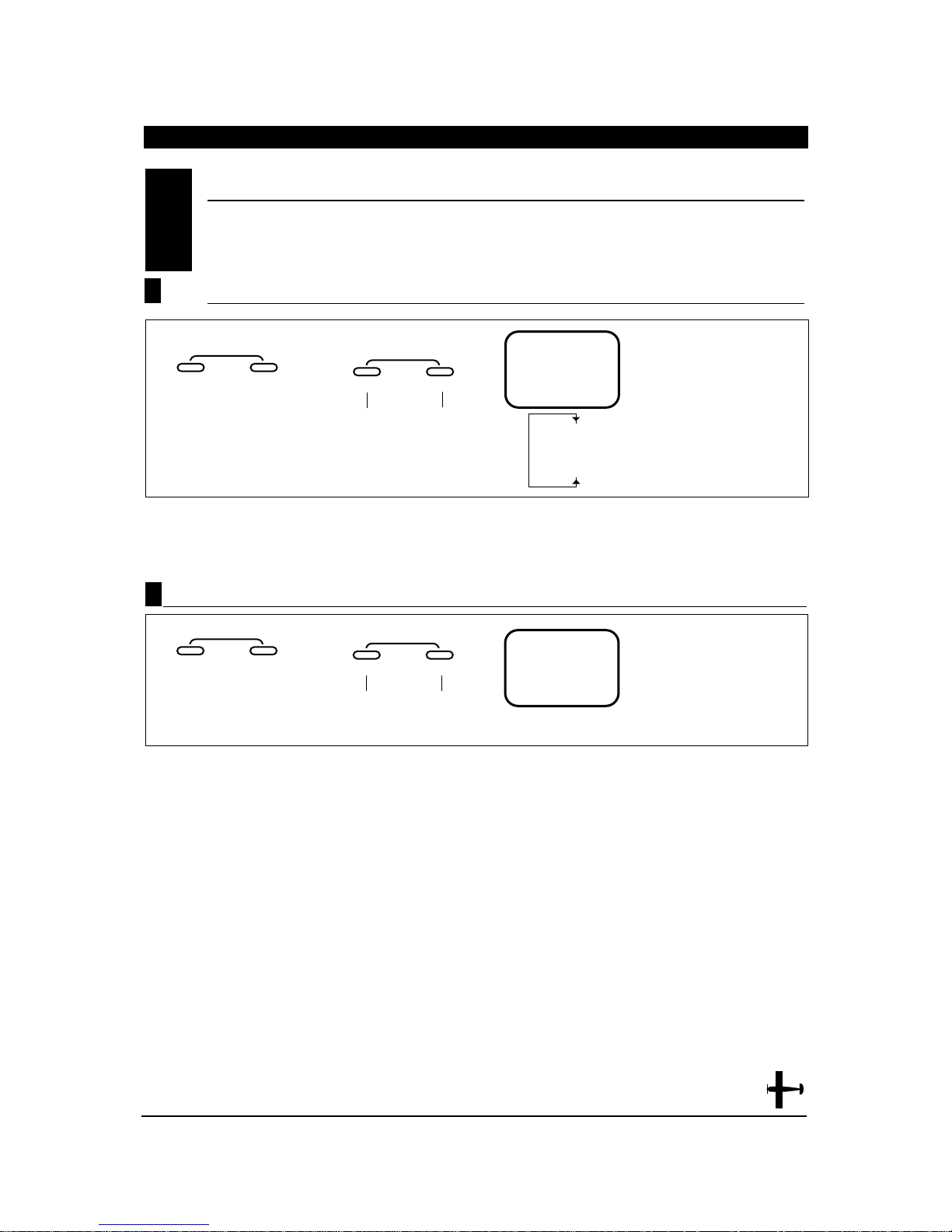
FAIL-SAFE/HOLD FUNCTION IN Z-PCM MODULATION(System Mode)
6.9
The Hold Function is automatically activated when
the radio is turned ON and is in the Z-PCM
modulation.
This function stops (or holds) the servos in the
positions they were in just prior to the interference.
Therefore, your airplane maintains the position held
immediately before the interference was experienced.
When a clear signal is restored, the Hold Function
releases, and control of the airplane returns to you.
If you would prefer your control surfaces to move to a
chosen position during a loss of signal, please refer to
the time delay/memory section below.
Hold (Z-PCM)
Accessing Fail-Safe/Hold (Z-PCM)
When the Fail-Safe Function is activated (i.e., when
the signal is interrupted), the transmitter
automatically moves each servo to a preset position.
The position that each servo assumes is determined
by you, as is the time length of interference that must
occur before servo movement.
After the interference has ceased, control of the
airplane returns immediately to you.
There are three time delays to choose from: 1/3 (0.3)
second, 1/2 (0.5) second and 1.0 second. These time
delays are the amount of time it takes, starting the
moment the interference occurs, until the servos
assume their preset positions.
1. Press the MODE and CHANNEL button
simultaneously and hold.
2. Turn on the transmitter to enter the System
Mode.
3. Press the MODE button until FST appears on the
screen.
Note: If Fail-Safe does not appear on your LCD, it is
because you are transmitting in PPM. Fail-Safe is not
applicable in the PPM mode. Refer to the Modulation
Mode Selection Section for more information.
The Fail-Safe/Hold Function is available only when
you use the XP652 transmitter in either of the
PCM modulations – S-PCM or Z-PCM. This function
is designed to help minimize damage to your
airplane during a loss of signal to the receiver. The
servos either assume the fail-safe presets or hold the
last good signal position.
Note: In the PCM modulations, the Fail-Safe/Hold
Function cannot be totally disabled so that the servos
will react to interference in the same way as they do in
a PPM system. This is only possible with the use of a
PPM receiver and the transmitter in the PPM
modulation.
Note: Since the actual screen appearance varies,
depending on the modulation of your radio, refer
to the appropriate modulation section which follows
(Z-PCM, S-PCM).
As noted earlier, if you are in the PPM modulation, the
Fail-Safe/Hold Function is not applicable. Therefore,
the Fail-Safe/Hold Function will not appear on your
LCD in the PPM mode.
Refer to the Modulation Selection Section for more
information pertaining to the broadcast signal of your
XP652 transmitter.
FAIL-SAFE/HOLD (System Mode)
6.8
CHAPTER 6:FUNCTIONS • Airplane continued
30
XP652 MANUAL Airplane
Page 31
31
XP652 MANUAL Airplane
MODE
ENTER
CHANNEL
HO = ALLSERVOS HOLD
0.3 = 1/3 SECOND TIME DELAY
0.5 = 1/2 SECOND TIME DELAY
1.0 = 1 SECOND TIME DELAY
HO
FST
Setting Fail-Safe/Hold Time Delay/Memory In Z-PCM Modulation
Press either the + or - buttons
to select the desired time delay.
INCREASE
CLEAR
+–
DECREASE
HOLD
0.3 SECONDS
0.5 SECONDS
1.0 SECONDS
1. After accessing the Fail-Safe Function, it is now
time to adjust the Fail-Safe Time Presets.
2. Select among the three time delays (0.3, 0.5, or 1.0
seconds) by pressing either the + or - buttons
until the desired setting appears on the screen.
Note: If Hold position is selected (HO) this
function/screen will not be present.
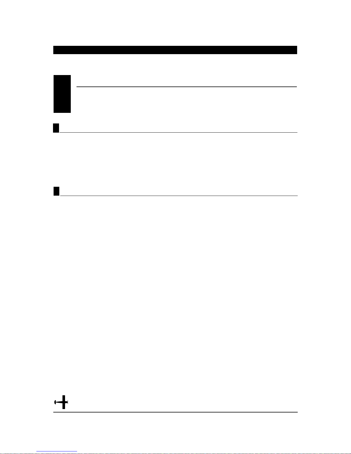
1. Press the MODE button until FSM appears on the
screen.
2. Set all controls to the desired fail-safe position,
then press the + and - buttons simultaneously. A
high pitch beep sound will confirm that the preset
positions have been entered.
3. Hold the transmitter sticks in the position that
you want the servos to assume during signal loss
conditions. You can determine fail-safe preset
positions for the other channels by placing the
control knobs and switches in the positions that
you want them to assume during interference.
4. With the sticks, switches and control knobs in
the fail-safe positions, press the + and - keys
simultaneously. This will enter these locations as
the fail-safe memory settings. A high pitched
beep will indicate that this setting has been
stored.
5. To confirm that the input of data was successful,
switch the transmitter OFF. The controls will move
to the input locations. If not, repeat step 4 again.
6. To exit the Fail-Safe Function, press the MODE
and CHANNEL buttons simultaneously.
Note: These preset positions remain stored in the
transmitter’s memory until both the transmitter
battery pack and the lithium back-up battery have
been removed (or until data reset has been
performed). Therefore, you do not have to reset the
fail-safe each time you fly. Should you want to readjust the fail-safe presets, access the Fail-Safe
Function and adjust the presets as you have
just done. The transmitter automatically recalls the
settings for the last fail-safe adjustment.
MODE
ENTER
CHANNEL
CL WILL FLASH WHEN FAIL-SAFE
SERVO POSITIONS ARE
ENTERED.
C
L
FS
M
Press the + or - buttons
simultaneously to store the fail-
safe servo presets.
INCREASE
CLEAR
+–
DECREASE
FAIL-SAFE/HOLD FUNCTION IN Z-PCM MODULA TION
6.9
Setting Servo Position Presets
Page 32
CHAPTER 6:FUNCTIONS • Airplane (System Mode) continued
32
XP652 MANUAL Airplane
The Hold Function is automatically activated when
the radio is turned ON and in the S-PCM modulation.
This function stops (or holds) the servos in the
positions they were in just prior to the interference.
Therefore, your aircraft maintains the position held
immediately before the interference was experienced.
When a clear signal is restored, the Hold Function
releases, and control of the airplane returns to you.
The XP652 allows you to combine the hold and fail-safe
presets for all six (6) channels on the receiver you can
select fail-safe or hold independently for all channels
on your aircraft. In other words, some channels will
hold their last clear signal position, while others
assume the preset position. Once the fail-safe has
been activated by signal interruption (interference), the
transmitter automatically moves the servos to a preset
position. The predetermined servo positions are set by
you. In the S-PCM fail-safe, the time delay (the amount
of time it takes, starting the moment the interference
occurs, until the servos assume the preset positions) is
fixed at .3, or 1/3, second.
After the interference has ceased, normal operation of
the airplane returns to you immediately.
Hold Function (S-PCM)
FAIL-SAFE/HOLD FUNCTION IN S-PCM MODULA TION(System Mode)
6.10
Fail Safe/Hold Combination in S-PCM Modulation
Page 33
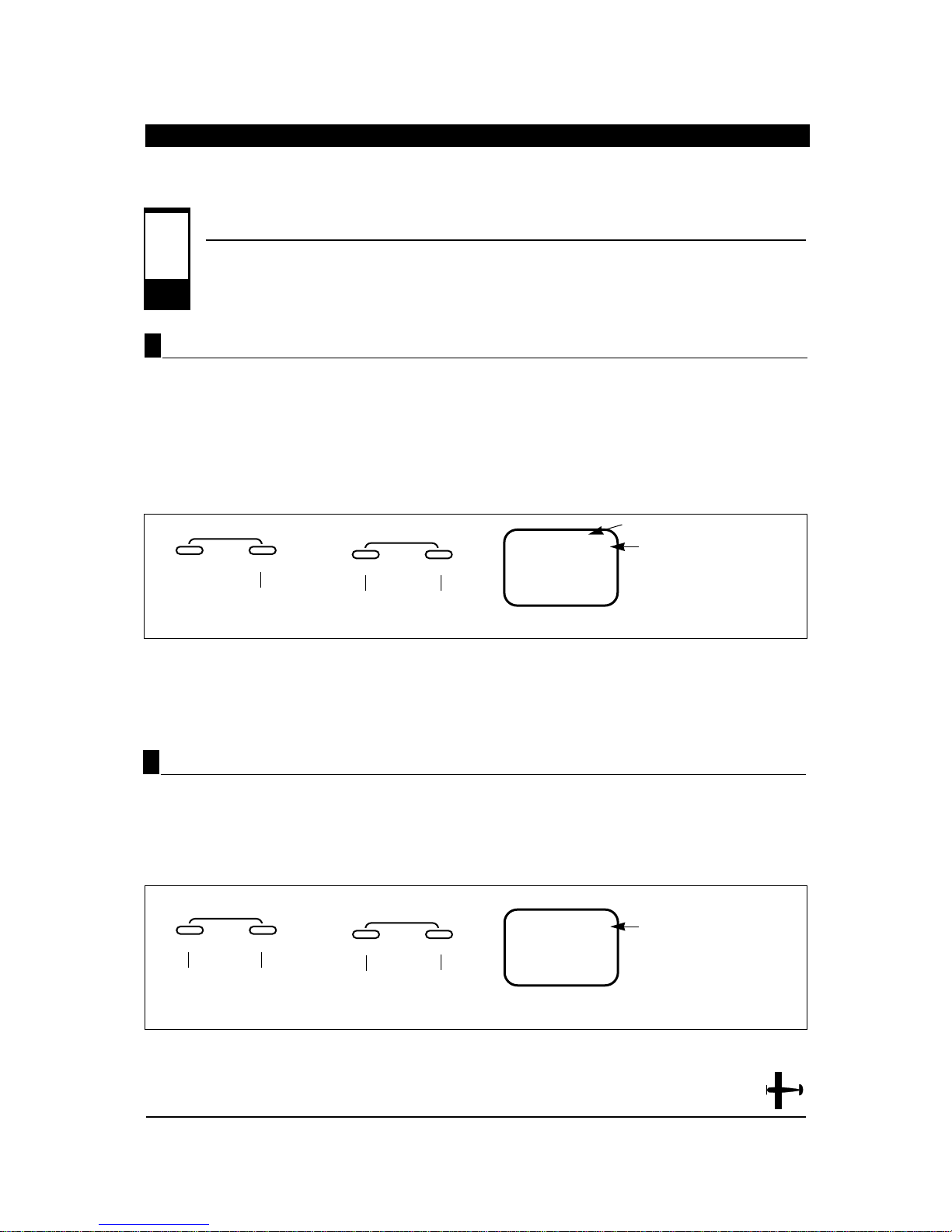
1. Press the MODE button until FSM appears on the
screen.
2. Set all controls to the desired Fail-Safe positions.
Next press the + or - button simultaneously. A high
pitch beep sound will confirm that the preset
positions have been entered and accepted.
MODE
ENTER
CHANNEL
SERVO PRESET MEMORY
CL WILL FLASH WHEN FAILSAFE SERVO POSITIONS
ARE ENTERED.
C
L
FS
M
Press the + and - buttons
simultaneously to store the
desired fail-safe presets/positions
Press the MODE and CHANNEL
buttons simultaneously to exit the
function mode
INCREASE
CLEAR
+–
DECREASE
FAIL-SAFE• Hold Memory in S-PCM Modulation (continued)
6.10
Setting Servo Fail-Safe Presets in S-PCM Modulation
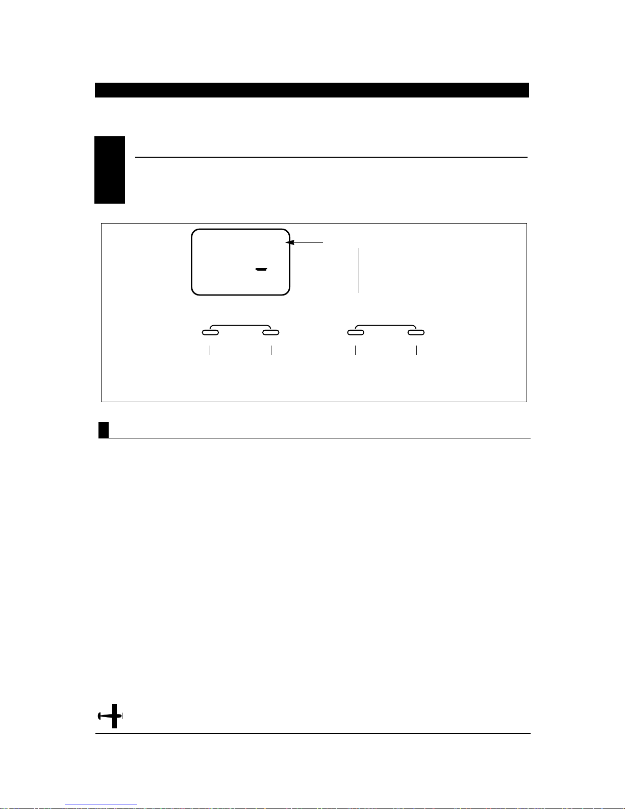
MODE
ENTER
CHANNEL
FAILSAFE
CURRENT CHANNEL
OF = HOLD
ON= PRESET SERVO
POSITION
OF
FS2
Press the + or - buttons to activate
the preset position function
Press the channel
button to access
channels 1-6
INCREASE
CLEAR
+–
DECREASE
1. Press the MODE and CHANNEL buttons
simultaneously and hold.
2. Turn on the transmitter to enter the system mode.
3. Press the MODE button until FS1 appears on the
screen. The #1 on the screen refers to the specific
channel (1-6) to be adjusted.
4. Press the + or - button to activate (turn on) the
preset position function for that channel.
5. Press the CHANNEL button to move to the next
channel(s) to be adjusted (2-6). Repeat Step 4 for
each channel to be activated.
Note: If Hold Position (HO) is selected for all
6 channels, this Function/Screen will not be
present.
Activating Servo Fail-Safe Pre-Sets by Channel (S-PCM)
33
XP652 MANUAL Airplane
Page 34
34
XP652 MANUAL Airplane
CHAPTER 7:FUNCTIONS • Airplane continued
Servo reversing is a very convenient function used
in the setup of a new aircraft. It is used to change
the direction of servo rotation in relation to the
corresponding stick movement. Servo reversing is
available for all 6 channels.
1. Turn on the transmitter.
2. Press the MODE and CHANNEL buttons
simultaneously to enter the function mode.
3. Press the MODE button until REV NORM appears
on the screen.
4. Press the CHANNEL button until the desired
channel appears on the screen.
5. Press the INCREASE or DECREASE button to
change the servo direction.
6. Press the MODE button to access the Dual Rate
function.
7. To exit, press the MODE and CHANNEL buttons
simultaneously.
Accessing the Servo Reversing Function
SERVO REVERSING• Function Mode
7.1
ENTER
MODE
Press the MODE
button until
◆
NORM
REV
appears on the
screen.
THR
REV◆NORM
CHANNEL INCREASE
Press the
CHANNEL button
until the desired
channel appears
on the screen.
CHANNEL
THR : THROTTLE
1
AIL : AILERON
2
ELE : ELEVATOR
3
RUD: RUDDER
4
GER: LANDING GEAR
5
FLP : FLAP (AC ONLY)
6
CLEAR
+
Press the INCREASE or DECREASE
button to change the servo direction.
–
DECREASE
Page 35
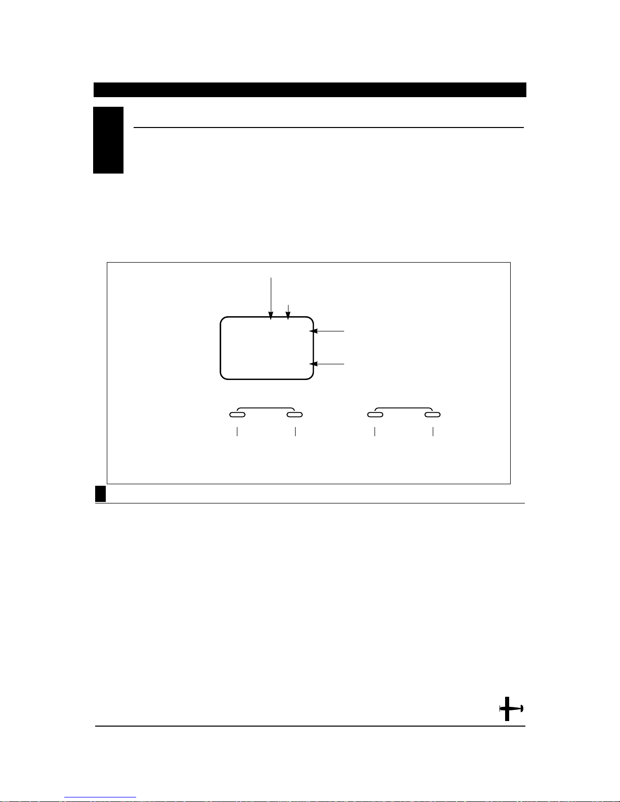
Dual rate is available for the aileron and elevator
channels. The purpose of this function is to allow
for in-flight selection of two preset servo travels for
each of these channels. The amount of travel is
adjustable from 0-125%. The factory settings for both
switch positions (0 and 1) is 100%. Either position may
be selected as the low or high rate by placing the
switches in the desired position and adjusting the
value for that position. Operation of these switches is
described in Section 6.3.
Different types of maneuvers require varying amounts
of control movements. Snap rolls require large control
movements, while smooth maneuvers like long slow
rolls are best performed with smaller control
movements. Dual rates allow you to change the control
movements in flight at the flip of a switch. This allows
you to execute maneuvers requiring both radical
control movements and small control movements
during a single flight.
1. Turn on the transmitter.
2. Press the MODE and CHANNEL buttons
simultaneously to enter the function mode.
3. Press the MODE button until D/R appears on the
screen.
4. Press the CHANNEL button until the desired
channel appears on the screen (AI = aileron or
EL = elevator).
5. The number that appears directly to the right of the
selected channel is the switch position. There are
two switch positions, 0 and 1, for each of the
channels. A 0 will appear when the selected dual
rate switch is in the uppermost position and a 1
when the selected switch is in the lower position.
6. To change the switch selection you must enter the
dual rate switch selection function in the system
mode (see Section 6.3).
7. The number in the center of the screen indicates
the current dual rate value for the selected switch
position and channel. Press the INCREASE or
DECREASE button to adjust the dual rate value
(0 –125%).
8. After adjusting the value for the 0 switch position,
change to the 1 switch position and adjust the
rates.
9. Press the CHANNEL button to select the other
channel and adjust the dual rate value for both
switch positions.
10. Press the MODE button to access the Exponential
Rate feature.
11. To exit, press the MODE and CHANNEL buttons
simultaneously.
DUAL RA TE• Function Mode
7.2
SWITCH POSITION (0 OR 1)
DUAL RATE VALUE (0-125%)
–
+
MODE
ENTER
CHANNEL INCREASE
CLEAR
DECREASE
Press the INCREASE or DECREASE
button to adjust the dual rate value.
Press the MODE
button until D/R
appears on the
screen.
Press the
CHANNEL button
until AI or EL
appears on the
screen.
D/R
AIO
I00
%
INDICATES THE DUAL RATE FUNCTION
CHANNEL
AI : AILERON
EL: ELEVATOR
Accessing the Dual Rate Function
35
XP652 MANUAL Airplane
Page 36
36
XP652 MANUAL Airplane
CHAPTER 6:FUNCTIONS • Airplane continued
Programmable exponential adjustments are offered
on the aileron and elevator channels of your XP652
system. Exponential is a function that allows you to
tailor the response rate of the controls as compared
to the stick inputs. The purpose of exponential is to
reduce the sensitivity in the middle portion of stick
movement, while still allowing full travel at the end of
the stick movement. In other words, the end result
(travel) remains the same, although exponential
changes the rate at which it achieves this travel.
The adjustable range of the Exponential Function is
from 0–100%. Zero percent (0%) is linear stick control
which means that the response rate is equal
throughout the stick control. One hundred percent
(100%) is full exponential. The larger the exponential
value, the less servo action, or sensitivity, you will
notice around the neutral setting.
Note: The Exponential Function operates in
conjunction with the Dual Rate Function. It is
imperative to understand the Dual Rate Function prior
to adjusting the exponential values.
Exponential may be selected independently for either
the high or low rate (position 0 or 1), or both.
EXPONENTIAL• Function Mode
7.3
Accessing the Exponential Function
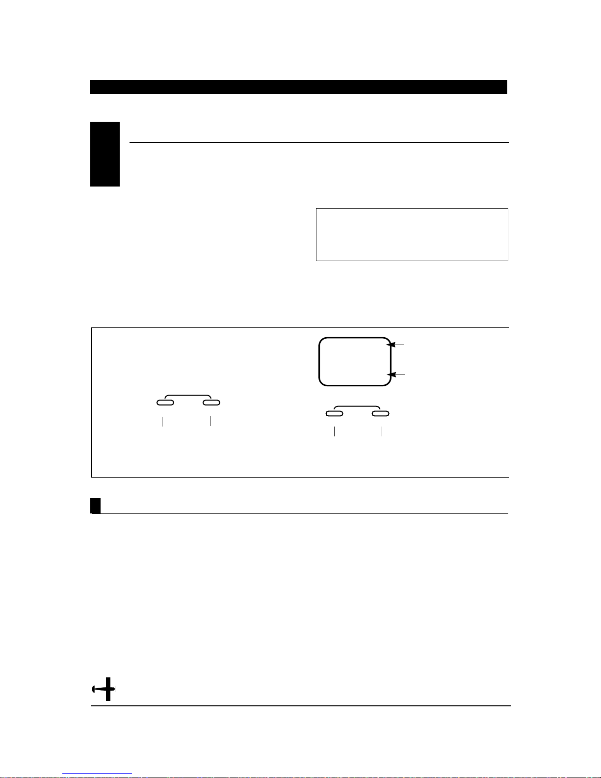
1. Turn on the transmitter.
2. Press the MODE and CHANNEL buttons
simultaneously to enter the Function Mode.
3. Press the MODE button until EXP appears at the
left side of the screen.
4. Press the CHANNEL button until the desired
channel appears on the screen (AI or EL).
5. Using the appropriate dual rate switch, select the
correct position to be adjusted (0 or 1).
6. Press the + or - buttons to increase/decrease the
exponential value.
7. Press the MODE button to access the sub-trim
Function.
8. To exit, press the MODEand CHANNEL buttons
simultaneously.
MODE
ENTER
CHANNEL
SWITCH POSITION
AI = AILERON
EL = ELEVATOR
EXPONENTIAL VALUE
0
%
AIO
Press the + and - buttons to
increase/decrease the
exponential valve (0 - 100%)
Press the MODE
button until EXP
appears on the left
side of the screen
Note: The dual rate switch position is
changed/accessed by setting the appropriate
dual rate switch to the 0 or 1 positions.
Press the CHANNEL
button to select either
aileron or elevator
exponential
INCREASE
CLEAR
EXP
+–
DECREASE
A GOOD STARTING
POINT FOR
EXPONENTIAL VALUE
IS APPROXIMATELY
20% – 30%.
Page 37
Accessing the Sub-T rim Function
Sub-trim is an electronic trim that is available for
each of the 6 channels. Sub-trim is particularly
useful as it allows the mechanical trim levers to be
returned to their neutral positions by adjusting
/changing the servo’s neutral position electronically,
without the need to mechanically adjust the specific
control linkage. This allows the same mechanical trim
lever settings between the four models you can control
with this radio system. Sub-trim can also allow
additional trim travel when mechanical trims do not
provide enough movement.
Note: It is recommended to use as little subtrim as
possible for adjustment. If more that 20-30 points are
required, is it suggested that a mechanical linkage
adjustment be performed.
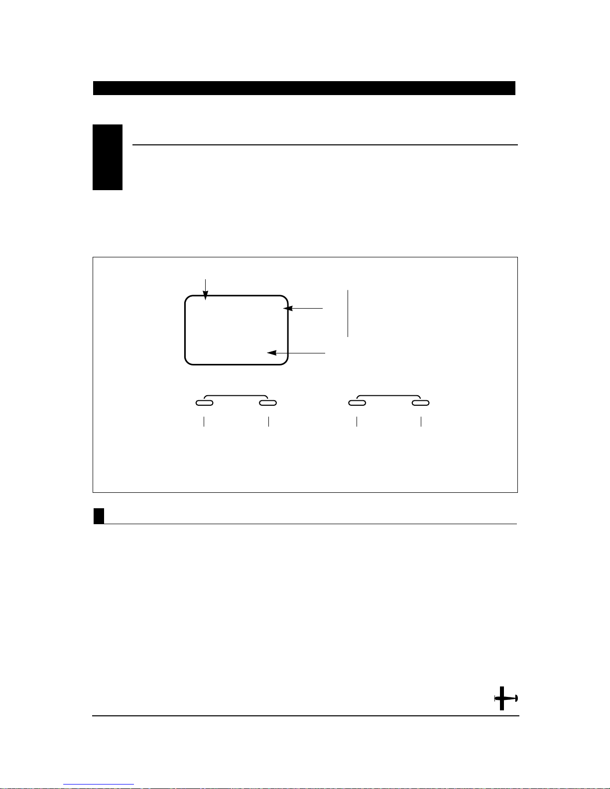
1. Turn on the transmitter.
2. Press the MODE and CHANNEL buttons
simultaneously to enter the function mode.
3. Press the MODE button until SB-Trim appears on
the screen.
4. Press the CHANNEL button until the desired
channel appears on the screen.
5. Press the INCREASE or DECREASE button to
establish the desired amount of sub-trim.
6. Press the MODEbutton to access the travel
adjustment function.
7. To exit, press the MODE and CHANNEL buttons
simultaneously.
SUB-TRIM• Function Mode
7.4
37
XP652 MANUAL Airplane
subtrim
INDICATES THE
SUB-TRIM FUNCTION
SB-TRIM
CHANNEL
THR
0
ENTER
MODE
Press the
MODE button
until SB-TRIM
appears on
the screen.
CHANNEL INCREASE
Press the
CHANNEL button
until the desired
channel appears
on the screen.
THR : THROTTLE
1
AIL : AILERON
2
ELE : ELEVATOR
3
RUD: RUDDER
4
GER: LANDING GEAR
5
FLP : FLAP (AC ONLY)
6
SUB-TRIM VALUE (±125)
CLEAR
+
Press the INCREASE or DECREASE
button to adjust the sub-trim value.
–
DECREASE
Page 38
38
XP652 MANUAL Airplane
CHAPTER 7:FUNCTIONS • Airplane continued
The amount of servo travel is adjustable for each
direction for each of the 6 channels individually.
The adjustment range is from 0% to 150%. Travel
adjustment is factory set at 100% for all channels.
The travel adjustment value displayed on the screen
depends on the position of the stick or switch (e.g.,
flap switch, gear switch). This function is useful either
to maximize control surface travel, or to reduce travel
to eliminate servo binding without the need for
mechanical adjustment.
1. Turn on the transmitter.
2. Press the MODE and CHANNEL buttons
simultaneously to enter the function mode.
3. Press the MODE button until TRV ADJ. appears on
the screen.
4. Press the CHANNEL button until the desired
channel appears on the screen.
5. Move the selected channel stick or switch in the
direction that you want to adjust the travel. Press
the INCREASE or DECREASE button to achieve the
desired travel. Move the stick in the opposite
direction to adjust the travel in the opposite
direction.
6. The same may be done for all channels.
7. Press the MODE button to access the aileron to
rudder mixing function.
8. To exit, press the MODE and CHANNEL buttons
simultaneously.
TRV ADJ.
THR
+I00
%
THR : THROTTLE
AIL : AILERON
ELE : ELEVATOR
RUD: RUDDER
GER: LANDING GEAR
FLP : FLAP (AC ONLY)
CHANNEL
1
2
3
4
5
6
INDICATES THE TRAVEL
ADJUSTMENT FUNCTION
TRAVEL ADJUSTMENT VALUE
SERVO OPERATING DIRECTION
–
+
MODE
ENTER
CHANNEL INCREASE
CLEAR
DECREASE
Press the INCREASE or DECREASE
button to adjust the travel adjustment value.
Press the
MODE button
until TRV ADJ.
appears on
the screen.
Press the
CHANNEL button
until the desired
channel appears
on the screen.
Accessing the T ravel Adjustment Function
TRAVEL ADJUSTMENT• Function Mode
7.5
Page 39
On some types of aircraft, it is desirable to mix
aileron and rudder to make coordinated turns. The
XP652 allows the mixing of ailerons to rudder and
allows you to adjust the amount and direction of
mixing. The aileron to rudder mixing can be left on all
the time, or it can be turned off with the selection of
one of three switches.
1. Turn on the transmitter.
2. Press the MODE and CHANNEL buttons
simultaneously to enter the function mode.
3. Press the MODE button until MIX A-R appears on
the screen.
4. Press the INCREASE or DECREASE button to set
the desired amount and direction of aileron to
rudder mixing.
Note: If OF appears on the screen it is because the
aileron to rudder mixing switch is in the off
position.
Accessing the Aileron to Rudder Mixing Function
AILERON TO RUDDER MIXING• Function Mode
7.6
39
XP652 MANUAL Airplane
MIX
A-R
%
+0
MIXING DIRECTION
ENTER
MODE
Press the MODE button
until MIX A-R appears on the
screen.
CHANNEL INCREASE
INDICATES THE AILERON TO
RUDDER MIXING FUNCTION
MIXING VALUE (0-125%)
Press the INCREASE and DECREASE
buttons simultaneously to set the
aileron to rudder mixing direction.
CLEAR
+
Press the INCREASE or DECREASE button
to set the aileron to rudder mixing value.
–
DECREASE
Page 40
40
XP652 MANUAL Airplane
CHAPTER 7:FUNCTIONS • Airplane continued
1. Follow Steps 1 through 4 as above.
2. Press the CHANNEL button until MIX ARS appears
on the screen.
3. Press the INCREASE or DECREASE button until
the desired switch selection appears on the screen.
4. Press the MODE button to access the elevator to
flap mixing function.
5. To exit, press the MODE and CHANNEL buttons
simultaneously.
Accessing the Aileron to Rudder Mixing Switch Function
AILERON TO RUDDER MIXING (continued)7.6
AILERON TO RUDDER MIXING SWITCH SELECTION
ARS
MIX
ON
INDICATES THE AILERON TO
RUDDER MIXING SWITCH FUNCTION
MIXING SWITCH
ON = MIXING IS ALWAYS ACTIVATED
S = GEAR SWITCH
A = AILERON DUAL RATE SWITCH
F1 = FLAP SWITCH
MODE
ENTER
CHANNEL INCREASE
Press the CHANNEL
button unti MIX ARS
appears on the screen.
+
Press the INCREASE or DECREASE
button until the desired switch selection
appears on the screen.
CLEAR
–
DECREASE
Page 41

Elevator to flap mixing is commonly used to
quicken the pitching rate of an aircraft. This is very
popular in fun fly airplanes because it allows
tighter loops. Normally, with up elevator the flaps go
down, while down elevator makes the flaps go up.
1. Turn on the transmitter.
2. Press the MODE and CHANNEL buttons
simultaneously to enter the function mode.
3. Press the MODE button until MIX E-F appears on
the screen.
4. Press the INCREASE or DECREASE button to set
the elevator to flap mixing value.
5. Press the INCREASE and DECREASE buttons
simultaneously to set the elevator to flap mixing
direction.
Accessing the Elevator to Flap Mixing Function
ELEVATOR TO FLAP MIXING •FUNCTION MODE7.7
41
XP652 MANUAL Airplane
MIX
E-F
%
+0
MIXING DIRECTION
ENTER
MODE
Press the MODE button
until MIX E-F appears
on the screen.
CHANNEL INCREASE
INDICATES THE ELEVATOR TO
FLAP MIXING FUNCTION
MIXING VALUE (0-125%)
Press the INCREASE and DECREASE
buttons simultaneously to set the
elevator to flap mixing direction.
CLEAR
+
Press the INCREASE or DECREASE button
to set the elevator to flap mixing value.
–
DECREASE
Page 42
42
XP652 MANUAL Airplane
CHAPTER 7:FUNCTIONS • Airplane continued
1. Follows Steps 1 through 4 as above.
2. Press the CHANNEL button until MIX EFS appears
on the screen.
3. Press the INCREASE or DECREASE button until
the desired switch designation appears on the
screen.
4. Press the MODE button to access the differential
function if flaperons or delta wing types are
activated in the system mode. If flaperons are not
activated, pressing the
MODE
button will access
the flap to elevator offset function.
5. To exit, press the MODE and CHANNEL buttons
simultaneously.
Accessing the Elevator to Flap Mixing Switch Function
ELEVATOR TO FLAP MIXING(continued)7.7
ELEVATOR TO FLAP MIXING SWITCH SELECTION
EFS
MIX
ON
INDICATES THE ELEVATOR TO FLAP
MIXING SWITCH FUNCTION
MIXING SWITCH
ON = MIXING IS ALWAYS ON
S = LANDING GEAR SWITCH
E = ELEVATOR DUAL RATE
F0 = FLAP SWITCH
ENTER
MODE
CHANNEL INCREASE
Press the CHANNEL
button until EFS appears
on the screen.
Press the INCREASE or DECREASE
button until the desired switch
designation appears on the screen.
CLEAR
+
–
DECREASE
Page 43
Accessing the Differential Function• Flaperon/Delta Mode Only
Aileron differential is used to correct roll to yaw
coupling and adverse yaw characteristics. In order to
activate differential, the flaperon wing type must
have been selected in the system mode (see Section
6.4). Also, each aileron control surface must have its
own servo with the right aileron servo plugged into the
aileron channel (#2) on the receiver and the left aileron
servo plugged into the Flap Aux 1 channel (#6) on the
receiver.
1. Turn on the transmitter.
2. Flaperon wing type must be selected (see Section
6.4).
3. Press the MODE and CHANNEL buttons
simultaneously to enter the function mode.
4. Press the MODE button until MIX DIF appears on
the screen.
5. Press the INCREASE or DECREASE button to
adjust the differential mixing value.
6. Press the MODE button to access theflap to
elevator offset trim function.
7. To exit, press the MODE and CHANNEL buttons
simultaneously.
DIFFERENTIAL• Function Mode
7.8
43
XP652 MANUAL Airplane
DIF
MIX
%
0
ENTER
MODE
Press the MODE button
until MIX DIF appears
on the screen.
CHANNEL INCREASE
INDICATES THE
DIFFERENTIAL FUNCTION
DIFFERENTIAL VALUE (0 TO 100%)
CLEAR
+
Press the INCREASE or DECREASE
button to adjust the differential value.
–
DECREASE
Page 44
CHAPTER 7:FUNCTIONS • Airplane continued
44
XP652 MANUAL Airplane
When the flaps are deployed, most airplanes exhibit
pitching tendencies (most pitch nose up). Elevator
offset trim is designed to prevent this pitching. Flap
to elevator offset trim automatically retrims the
elevator to a preset value when the flap switch is
activated.
Note: Flap to elevator offset trim is also useful as a
dual elevator trim even for airplanes without flaps.
This is especially helpful for sailplanes that require
one trim setting for launch and another trim setting for
flight.
1. Turn on the transmitter.
2. Press the MODE and CHANNEL buttons
simultaneously to enter the function mode.
3. Press the MODE button until OFFSET F-E appears
on the screen.
4. Press the INCREASE or DECREASE button to set
the desired amount and direction of the elevator
offset.
Note: It is helpful to have the flap switch on when
making this adjustment.
5. Press the MODEbutton to access the
programmable mix function.
6. To exit, press the MODE and CHANNEL buttons
simultaneously.
Accessing the Flap to Elevator Offset T rim Function
FLAP TO ELEVATOR OFFSET TRIM• Function Mode
7.9
OFFSET
ENTER
MODE
Press the MODE button
until OFFSET F-E appears
on the screen.
F-E
INDICATES FLAP TO ELEVATOR
OFFSET TRIM FUNCTION
ELEVATOR OFFSET VALUE (±125)
0
+
CHANNEL INCREASE
Press the INCREASE or DECREASE
button to adjust the flap elevator
CLEAR
offset value.
–
DECREASE
Page 45
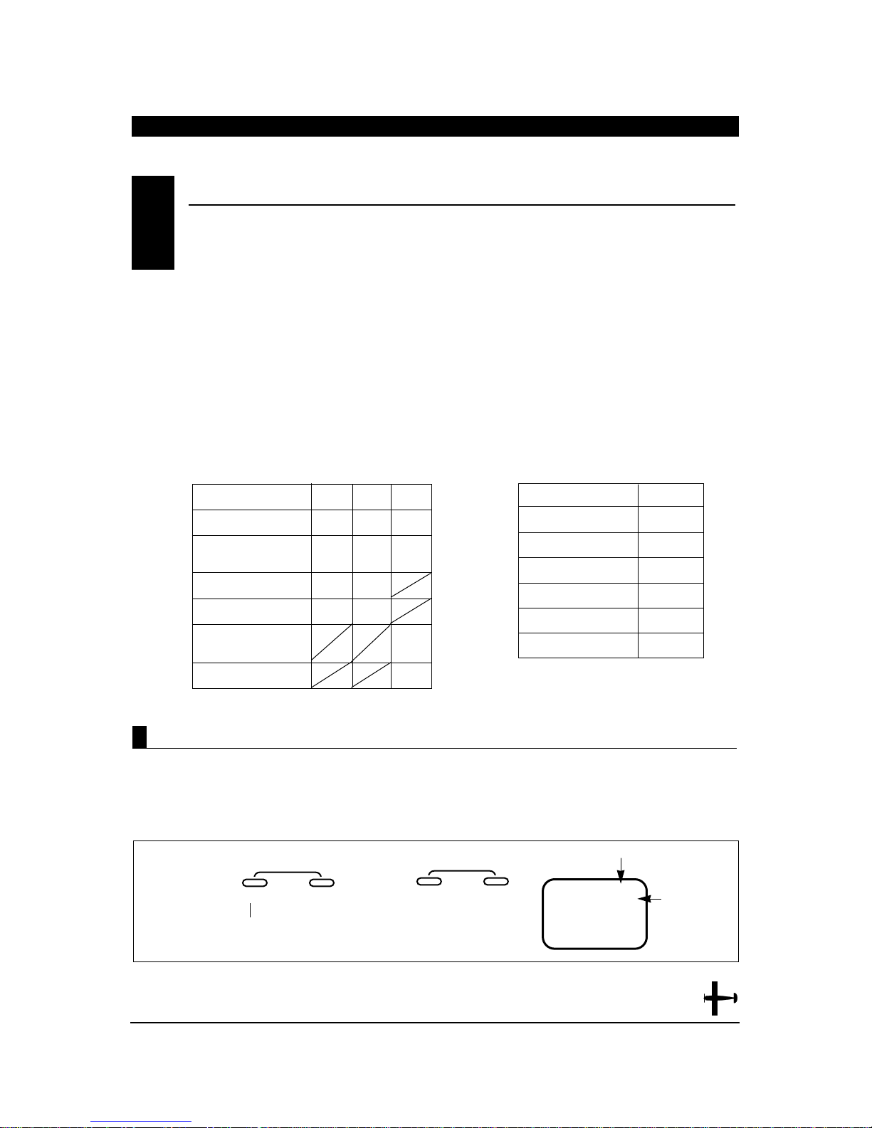
The XP652 in aircraft mode offers three (3)
programmable mixes to be used for a number of
different purposes. The functions allow mixing any
one channel to any other channel.
The mix can remain ON at all times, or be switched
OFF in flight using a number of different
switches. (Refer to Chart A). Each channel is identified
by channel numbers 1-6 (i.e., 2 = aileron, 4 = rudder,
etc. — See Chart B) The channel appearing first is
known as the “master channel,” or the channel to
which you want to mix. The second channel is known
as the “slave channel,” or the channel that is being
mixed into the master channel. For example, AILERUDD would indicate aileron to rudder mixing. Each
time the aileron stick is moved, the aileron will deflect,
and the rudder will automatically move in the
direction and to the value input. Mixing is
proportional, so small inputs of the master channel
will produce small outputs of the slave
channel. Each programmable mix has a mixing “offset.”
The purpose of the mixing offset is to redefine the
neutral position of the slave channel.
PROGRAMMABLE MIXING (A,B,C)• Function Mode
7.10
Accessing the Programmable Mixing Function
1. Turn on the transmitter
2. Press theMODE and CHANNEL buttons
simultaneously to enter the Function Mode
3. Press the MODE button until MIX A11 appears at
the top right corner of the screen. This is Program
Mix A. Pressing the MODE button again will select
mixes B and C.
A B C
ON ON ON
F1 F1 F1
A A
E E
FO
5
MIX
Chart A Switch Selection
SWITCH
Always ON
Flap/Mix Switch
Position 1 ON
Aileron DIR Switch
Elevator DIR Switch
Flap/Mix Switch
Position O ON
Gear/Mix Switch
FUNCTION
Throttle
Aileron
Elevator
Rudder
Gear
Flap
Chart B Channel Numbers
CHANNEL NUMBER
1
2
3
4
5
6
MODE
ENTER
CHANNEL
0
%
AII
Press the MODE button until
MIX A11 appears
CURRENT MIX
CURRENT
MIX
CHANNELS
INCREASE
CLEAR
MIX
+–
DECREASE
45
XP652 MANUAL Airplane
Page 46
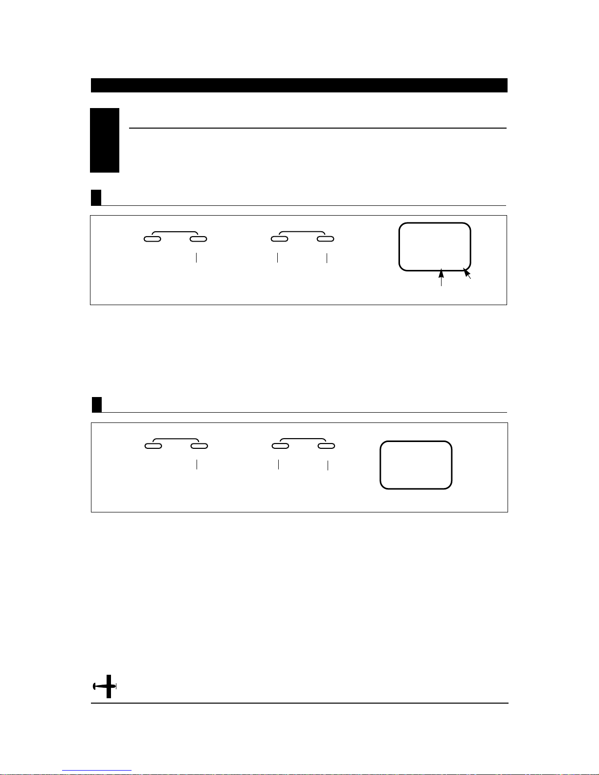
46
XP652 MANUAL Airplane
CHAPTER 7:FUNCTIONS • Airplane continued
1. Press the CHANNEL button once until MIX ASW
appears.
2. Press the + or - button to select the desired switch
to be used to activate the mixing, or leave as ON if
a constant mix is desired.
(Refer to Chart A on the preceding page for possible
mix/switch selections.)
1. Press the channel button twice until MIXA CH
appears on the screen.
2. Press the + button to select the desired
“
Master
Channel” (1-6).
3. Press the - button to select the desired “slave
channel” (1-6). Refer to Chart B on the preceding page
for channel number clarification.
PROGRAMMABLE MIXING (A,B,C)• Function Mode (continued)
7.10
MODE
ENTER
CHANNEL
24
ACH
Press the CHANNEL button
until MIX Ach appears.
Press to select
“Master”
channel desired.
Press to select
“Slave”
channel desired.
MASTER
CHANNEL
SLAVE
CHANNEL
INCREASE
CLEAR
MIX
+–
DECREASE
Assigning Channels
MODE
ENTER
CHANNEL
ON
A5W
Press the CHANNEL button
until MIX ASW appears.
Press the + or - buttons to select the
desired switch to be activated (refer
to Chart Aon preceding page).
SWITCH
CHOICES
ON
F1
A
E
FO
5
INCREASE
CLEAR
MIX
+–
DECREASE
Switch Selection
Page 47
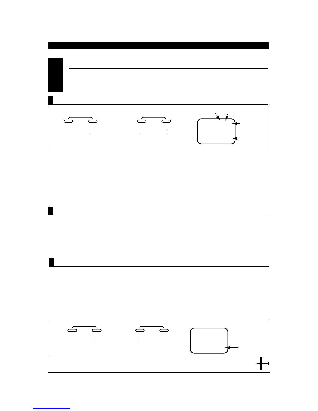
1. Press the CHANNEL button once until MIX A
appears, with the mixing value located at the
bottom of the screen.
2. To set the slave channels mixing value, move and
hold the master channel control stick to the
direction to be adjusted (up/down — left/right),
then press the + key to add + mixing value, or the
– key to add – mixing value (+/–125%). When the
master channels stick is moved, the display will
automatically show the mixing valve for the
current stick direction.
Note: If a mix switch position other than ON is
selected, it will be necessary to move the selected
switch to the ON, or active, position to adjust the
mixing value. OF will appear on the screen if the
selected mixing switch is in the off position.
The purpose of the mixing offset feature is to redefine
the neutral position of the slave channel to be mixed.
Any desired position may be selected for the offset
reference point. To set the offset position, place the
master channel’s stick to the desired position and
press either the + or - keys.
This position is now stored in the memory and its
offset value from the neutral position of the master
channel is indicated numerically on the LCD display.
Then, the mixing value at the determined offset
position is now set at 0.
PROGRAMMABLE MIXING (A,B,C)• Function Mode (continued)
7.10
MODE
ENTER
CHANNEL
0
%
A24
Press the CHANNEL
button once until MIX A
and MIX value % appears
Press either the + or - buttons to
increase/decrease mixing valve.
CURRENT MIX MASTER CHANNEL
SLAVE
CHANNEL
CURRENT
MIXING
VALUE
INCREASE
CLEAR
MIX
+–
DECREASE
MODE
ENTER
CHANNEL
0
A24
Press the CHANNEL
button until OFFSET
appears on the screen.
Press either the + or - buttons to
slave the offset position.
OFFSET
MIXING
VALUE
INCREASE
CLEAR
MIX
OFFSET
+–
DECREASE
Mixing Value Adjustment
Mixing Offset Adjustment
Accessing the Offset Function
47
XP652 MANUAL Airplane
1. Press the CHANNEL button once until offset
appears in the center of the screen.
2. Place the master channel stick to the desired
position of slave channel offset, then press either
the + or - button to store.
3. Press the MODE button once to access Program
Mix B, press twice to access program MIX C, and a
third time to access the trim offset memory
function.
4. To exit the Function Mode, press the Mode and
CHANNEL buttons simultaneously.
Note: If a mix switch position other than ON has been
selected, it will be necessary to move the selected
switch to the ON, or active, position to set the offset
value. OF will appear on the screen if the selected
mixing switch is in the OFF position.
Page 48
48
XP652 MANUAL Airplane
The Trim Offset Memory Function of your XP652
allows you to test fly your aircraft and correct for
any built-in trim requirements. After you adjust the
aileron, elevator and/or rudder trim levers during
the test flights, the trim levers are no longer in their
center, or neutral, positions. The use of trim offset
allows you to return the trims to their center, or
neutral, positions without readjusting the control
surface linkages mechanically.
This function is very useful when switching from model
to model. It allows your trims to remain in their
neutral positions while retaining their corrections.
Using this feature, you can easily switch among the
five (5) model memories without the need to readjust
for each aircraft’s individual trim requirements.
1. First, test fly your aircraft and adjust the aileron,
elevator and/or rudder trim levers. After all
adjustments have been made, land your airplane.
DO NOT adjust/reposition any of the trim levers at
this time.
CAUTION: Do not attempt to adjust the Trim Offset
Memory Function while your model’s engine is
running. Please stop your aircraft’s engine before
entering the Function Mode.
2. Turn on the transmitter.
3. Press the MODE and CHANNEL buttons
simultaneously to enter the Function Mode.
4. Press the MODE button until TRM offset appears
on the screen.
TRIM OFFSET MEMORY
7.11
Accessing the T rim Offset Memory Function
MODE
ENTER
CHANNEL
TR
M
Press the MODE button
until TRM OFFSET
appears on the screen.
TRM-TRIM
OFFSET
INCREASE
CLEAR
OFFSET
+–
DECREASE
A.
MODE
ENTER
CHANNEL
+C
L
M
OV
Press the + or - buttons; MOV
+CL should appear on the screen
MOVE TRIM LEVERS
TO THEIR CENTER/
NEUTRAL POSITIONS
PRESS THE + AND BUTTONS
SIMULTANEOUSLY
TO STORE
INCREASE
CLEAR
OFFSET
+–
DECREASE
B.
5. Press the + or - keys. MOV + CL should appear on
the screen.
Accessing the T rim Offset Memory Function
CHAPTER 7:FUNCTIONS • Airplane (Function Mode)
Page 49
TRIM OFFSET MEMORY (continued)
7.11
6. Move all trim levers to their center positions, then
press the + and - buttons simultaneously to store
the trim offsets. The screen should appear as shown:
7. Press the MODE and CHANNEL buttons
simultaneously to exit the function mode.
Accessing the T rim Offset Memory Function(continued)
If OVR appears on the screen when the trim levers are
moved to their center positions, this indicates that the
amount of offset trim for one or more channels is in
excess of the acceptable limits. If this situation occurs,
a mechanical adjustment of the control linkage will be
necessary.
Over T rim
MODE
ENTER
CHANNEL
TR
M
Press the + or - buttons
simultaneously to store the
trim offset.
OFFSET FUNCTION
MEMORIZED/
COMPLETE
INCREASE
CLEAR
OFFSET
+–
DECREASE
C.
--
OVR
TRIM VALUE EXCEEDS
ACCEPTABLE LIMITS(over)
LINKAGE ADJUSTMENT
NECCESSARY
OFFSET
This feature is useful if you wish to clear all trim offset
stored within the XP652’s memory without affecting
the data stored for other functions. The most common
use for this feature is if you have disassembled/
repaired your model and would like to return all
servos/trims to their “true neutral” positions before
linkage installation/initial test flights.
Clearing T rim Offset Memory
49
XP652 MANUAL Airplane
Page 50
50
XP652 MANUAL Airplane
TRIM OFFSET MEMORY(continued)
7.11
MODE
ENTER
CHANNEL
TR
M
Press the MODE button until
TRM OFFSET appears on
the screen.
INCREASE
CLEAR
OFFSET
+–
DECREASE
A.
MODE
ENTER
CHANNEL
C
L
TR
M
Press the channel button
once until CL appears on
the screen.
CL = Clear
Trim Offset
INCREASE
CLEAR
OFFSET
+–
DECREASE
B.
MODE
ENTER
CHANNEL
0
TR
M
Press the MODE and CHANNEL buttons
simultaneously to exit the function mode.
INDICATES
THATALL
TRIM OFFSET
MEMORY
VALUES ARE
SET TO 0%
(NEUTRAL)
INCREASE
CLEAR
OFFSET
+–
DECREASE
Press the + and - buttons simultaneously to
reset the offset trim valves to 0% (neutral).
C.
1. Turn on the transmitter
2. Press the MODE and CHANNEL buttons
simultaneously to enter the Function Mode.
3. Press the MODE button until TRM OFFSET appears
on the screen.
4. Press the CHANNEL button once; CL should
appear at the bottom of the screen:
5. Press the + and - buttons simultaneously .0 should
appear on the screen indicating that the offset trim
memory has been reset to 0, or neutral trim.
6. Press the MODE and CHANNEL buttons
simultaneously to exit the function mode.
Accessing the Offset T rim Clear Function
CHAPTER 7:TRIM OFFSET MEMORY • Airplane
Page 51
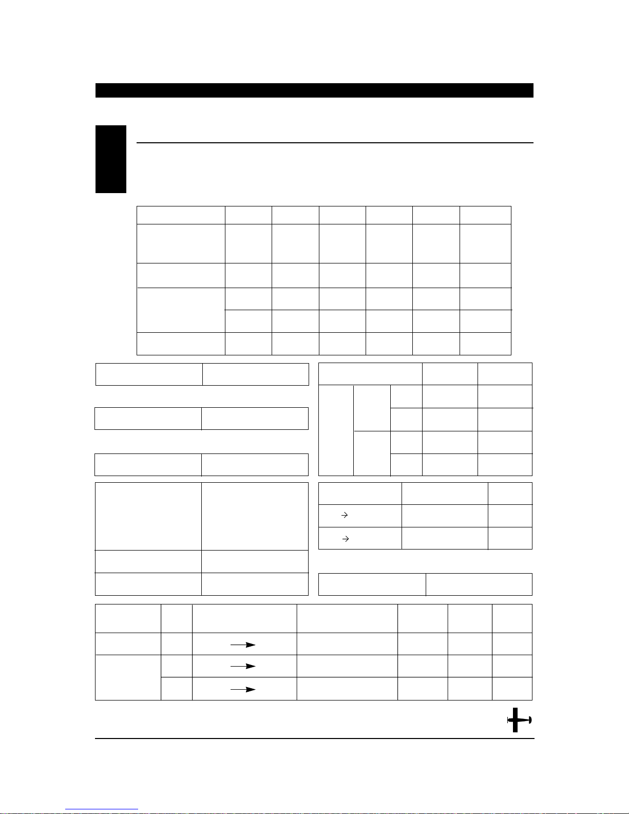
DA T A SHEETS
CHAPTER 8:DAT A SHEET • XP652 Airplane
8
NORM NORM NORM NORM NORM NORM
••••• •
REV REV REV REV REV REV
SUB TRIM
TRAVEL ADJUST + % + % + % + % + % + %
(TRV ADJ.) - % - % - % - % - % - %
FAIL SAFE (SPCM)
REVERSE SW
CHANNELS THRO (1) AIL (2) ELE (3) RUDD (4) GER (5) AUX1 (6)
FAIL SAFE TIME (ZPCM)
AILE (AI) ELEV (EL)
D/R % %
EXP % %
D/R % %
EXP % %
POS O
POS 1
MIX SW POS
ON • 5 • A • F1 %
ON • 5 • E • F0 %
AILE RUDD MIX
DUAL
RATE
•
EXP
D/R SW
EA • A • E • CF
LANDING ELEV OFFSET
TRIM OFFSET
WING TYPE
PROG. MIX
A
B
C
CHANNEL
MASTER SLAVE MIX SWITCH OFFSET +GAIN -GAIN
ON • F1 • A • E
ON • F1 • A • E
ON • F1 • F0 • 5
V-TAIL
DIFFERENTIAL
ON • OFF
%
NORM
•
FLAPERON
•
DELTA
±
ELEV FLAP MIX
Modulation SPCM • ZPCM • PPM (FM)
Model Number _____________________
Model Name ______________________
51
XP652 MANUAL Airplane
Page 52
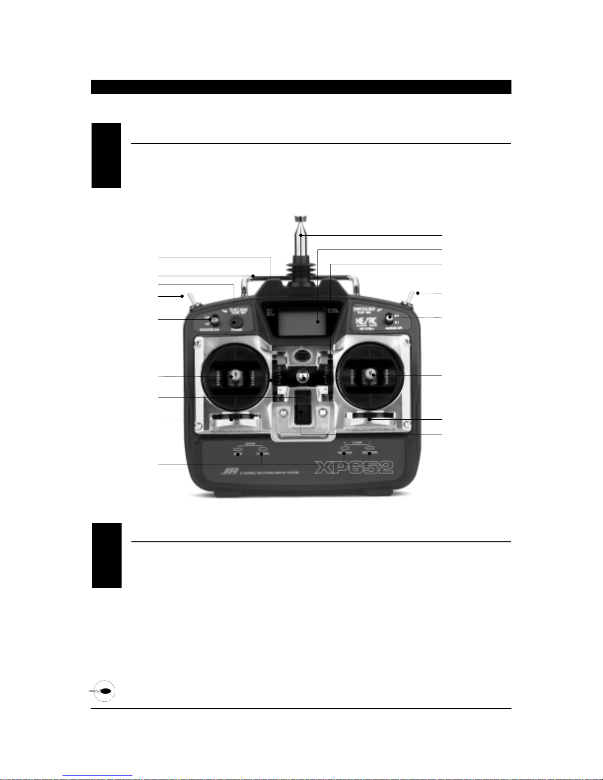
1. THRO Throttle Channel
2. AILE Aileron Channel
3. ELEV Elevator Channel
4. RUDD Rudder Channel
5. GEAR Gear Channel
6. AUX 1 Auxiliary 1 Channel (Pitch)
Transmitter Throttle ALT
The throttle ALT function makes the throttle stick
trim active only when the throttle stick is less than
half throttle. This gives easy, accurate idle
adjustments without affecting the high throttle
position.
52
XP652 MANUAL Helicopter
RECEIVER CHANNEL ASSIGNMENT/TRANSMITTER THROTTLE AL T1.2
CONTROL IDENTIFICA TION AND LOCA TION• Mode II
1.1
CHAPTER 1:TRANSMITTER CONTROLS • Helicopter
AUX 1/FLAP MIXING
AILERON DUAL RATE
ANTENNA
LCD SCREEN
GEAR SWITCH
ELEVATOR DUAL RATE
TRAINER BUTTON
AILERON/ELEVATOR STICK
THROTTLE/RUDDER STICK
POWER SWITCH
AILERON TRIM
ELEVATOR TRIM
THROTTLE TRIM
RUDDER TRIM
NECK STRAP EYELET
INPUT KEYS
CARRYING HANDLE
Page 53
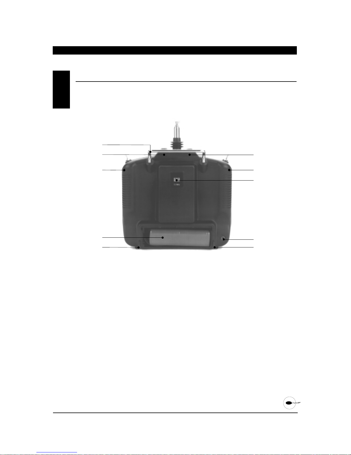
53
XP652 MANUAL Helicopter
CHAPTER 1:TRANSMITTER CONTROLS • Helicopter continued
TRANSMITTER REAR1.3
Note: Your transmitter has a 5-year lithium battery
to protect your pre-programmed data against main
transmitter battery failure. If you system reads 0.0
volts, or has an unfamiliar display (service mode) or
your data resets to the factory defaults, return your
transmitter to Horizon Service Center (see page 94)
for lithium battery replacement.
CARRYING HANDLE
TRANSMITTER
CASE SCREW
TRANSMITTER
CASE SCREW
BATTERY
TRANSMITTER
CASE SCREW
TRANSMITTER
CASE SCREW
TRANSMITTER
CASE SCREW
CRYSTAL
TRAINER JACK
TRANSMITTER
CASE SCREW
Page 54
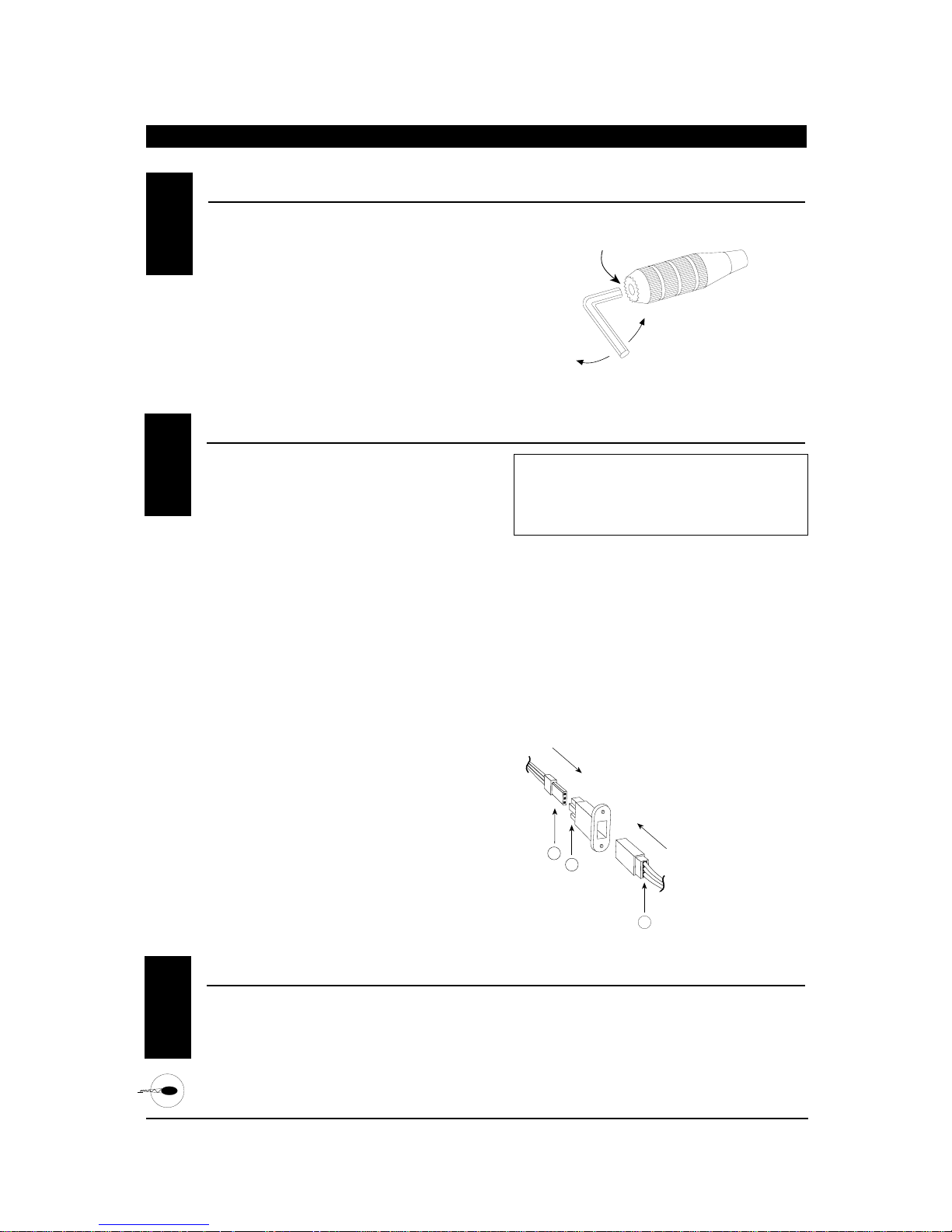
54
XP652 MANUAL Helicopter
DIRECT SERVO CONTROL (DSC)1.5
CONTROL STICK LENGTH ADJUSTMENT
CHAPTER 1:TRANSMITTER CONTROLS • Helicopter continued
1.4
NECK STRAP A TT ACHMENT1.6
To adjust the control stick length, use a 2mm Allen
wrench to unlock the set screw located inside the
end of the control stick. Turn the set screw
counterclockwise to loosen it, then turn the knurled
portion of the stick to adjust the length.
Counterclockwise will lengthen the stick and
clockwise will shorten it. After the control stick(s)
has been adjusted to suit your flying style, tighten
the set screw back.
For proper DSC hook-up and operation:
1. Leave the transmitter power switch off. The
transmitter will not transmit any radio
frequency (RF) in this position.
2. Plug the optional DSC cord (JRPA132) into the
DSC port in the rear of the transmitter.
3. The encoder section of the transmitter will now
be operational and the LCD display will be lit.
4. Plug the other end of the DSC cord into the
receiver charge receptacle. Turn on the switch
harness.
Note: When installing the optional charging jack
(JRPA024) be sure to hook the charging jack
receptacle securely into the switch harness charge
cord.
Why you should use the DSC function:
1. The DSC enables you to check the control
surfaces of your aircraft without drawing the
fully operational 200mAh from your transmitter
battery pack. Instead, you will only draw 70mAh
when using the DSC function.
Note: You will need to purchase (separately) both
the DSC Cord (JRPA132) and the JR Deluxe Switch
Harness (JRPA001) to make use of the XP652 DSC
Function.
2. The DSC function allows you to make final
adjustments to your airplane or helicopter
without transmitting any radio signals.
Therefore, if another pilot is flying on your
frequency, you can still adjust your aircraft and
not interfere with the other aircraft.
Note: Under no circumstances should you attempt
to fly your aircraft with the DSC cord plugged in! This
feature is for bench checking your aircraft only.
There is an eye hook on the front of the transmitter
for attaching an optional neck strap (JRPA023). The
eye hook is precisely positioned (see Section 1.1) so
that the transmitter will be perfectly balanced when
a neck strap is used.
A
B
C
A - Charge Cord/DSC Receptacle
B - Switch Harness Lead
C - Charger/DCS Cord
SET SCREW
LOOSEN
TIGHTEN
Page 55
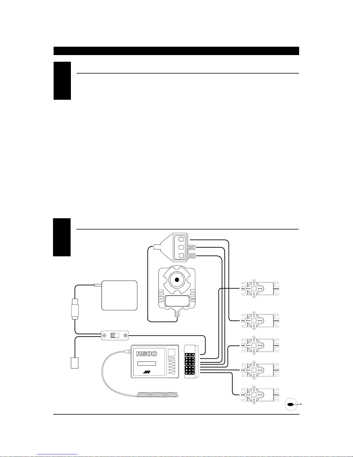
It is important to correctly install the radio system in
your model. Please read and carefully follow the
suggestions listed below.
1. For added protection, wrap the Rx and the Rx
Nicad in foam rubber that is at least 1/4” thick.
2. Run the Rx antenna through the fuselage and
make sure it is fully extended. Never cut or
bundle your Rx antenna — this will decrease
range and performance.
3. Rubber servo grommets are included with your
radio system and should be installed in the servo
flanges. The servos should then be mounted on
either hardwood rails or a plywood tray with the
mounting screws provided. Do not overtighten
the mounting screws. The flange of the brass
eyelets should face down (toward the wood).
4. All servos must be able to move freely over the
full range of their travel. Make sure the linkages
do not impede servo travel. A stalled servo will
drain the battery pack within a few minutes.
5. Before installing servo output arms, make sure
the servo is in its neutral position.
6. In the case of gas-powered model aircraft, mount
the receiver power switch on the side of the
fuselage opposite the muffler to protect the
switch from exhaust residue. With other types of
models, mount the switch in the most
convenient place. Make sure that the switch
operates freely and is capable of traveling its full
distance.
7. With your model sitting on the ground and the
transmitter antenna collapsed, check that
your system works at a distance of 75 to 100
feet.
If your system stops functioning at a distance
that is shorter than listed above, please contact
the Horizon Service Center for further
information prior to flying your model.
55
XP652 MANUAL Helicopter
INST ALLA TION REQUIREMENTS
CHAPTER 2:CONNECTIONS • Helicopter
CONNECTIONS2.2
2.1
ON
OFF
RUDDER
ELEVATOR
AILERON
THROTTLE
ON/OFF SWITCH HARNESS
(JRPA003)
CHARGING PLUG
R-600 RECEIVER
ANTENNA
RECEIVER
BATTERY
B1000
6 CH 72MHz FM RECEIVER
MADE IN MALAYSIA
ABC&W INTERFERENCE
PROTECTION SYSTEM
BATT
AUX 1
GEAR
RUDD
ELEV
AILE
THRO
NEJ
-900
G900 Gyro (Optional)
PITCH
NEJ
-900
Page 56
56
BA TTERY ALARM AND DISPLAY
CHAPTER 4:BATTER Y ALARM AND DISPLA Y • Helicopter
4
–
+
MODE
ENTER
BUTTON USE
MODE Used to move up through the available functions
CHANNEL Used to select the desired channel
INCREASE Used to increase the value of the selected function
DECREASE Used to decrease the value of the selected function
CHANNEL INCREASE
CLEAR
DECREASE
Press the INCREASE and DECREASE
buttons simultaneously to clear the
screen or return to factory preset.
To enter the function mode press the
MODE and CHANNEL buttons
simultaneously while the transmitter is on.
To enter the system mode press the MODE
and CHANNEL buttons simultaneously and
hold while turning on the transmitter.
CHAPTER 3:KEY INPUT AND DISPLAY • Helicopter
KEY INPUT AND DISPLA Y3
XP652 MANUAL Helicopter
When the transmitter battery drops below 9.0 volts,
the display will start to flash BAT and an audible
alarm will sound for 8 beeps. These warnings mean
you should land your aircraft immediately.
Note: During the period that the battery alarm is
flashing, the input buttons will not function. If you
are currently in the function mode, the transmitter
will exit automatically and return to the normal
display (see Section 5.1).
BAT
8.9V
FLASHING
V
Page 57
57
SYSTEM MODE
CHAPTER 5:INPUT MODE AND FUNCTION • Helicopter
5.2
NORMAL DISPLA Y5.1
XP652 MANUAL Helicopter
When the power switch is turned on the screen will
read as shown here in the diagram. This screen is
referred to as the normal display.
To enter the system mode press the MODE and
CHANNEL buttons simultaneously while you turn on
the transmitter. You can now select any of 8 system
mode functions shown here in the flow chart. To exit
the system mode, press the MODE and CHANNEL
buttons simultaneously or turn off the transmitter.
Press the MODE button to move through the system
mode functions. Information for each function is
located on the page number listed next to the
function name.
I0.4V
HE I
MODEL NUMBER
AC = FIXED WING AIRCRAFT
HE = HELICOPTER
BATTERY VOLTAGE
I
MDL
I
HEI
I
SPC
FST
HE
TYP
HE
RST
E.A
SW
D/R
F
GER
OF
FSI
MODEL TYPE SELECTION
Page 59
DATARESET Page 60
DUAL RATE SWITCH
SELECTION
Page 61
GEAR/GYRO SWITCH
SELECTION
Page 62
MODEL SELECTION Page 63
MODEL NAME ENTRY
Page 64
MODULATION SELECT
Page 65
Page 66
*
(S-PCM)
*
(Z-PCM)
* Only visible when modulation type is selected for SPCM, or ZPCM modulation
FAIL-SAFE
FAIL-SAFE MEMORY
V
Page 68
Page 58
58
XP652 MANUAL Helicopter
FUNCTION MODE
CHAPTER 5:INPUT MODE AND FUNCTION
5.3
To enter the function mode, turn on the transmitter.
Press the MODE and CHANNEL buttons
simultaneously until a beep is heard. The display will
change accordingly and show the last active
function. Press the MODE button to scroll down
through the functions one by one as shown in the
flowchart at right. Once the appropriate function is
selected, use the CHANNEL button to select the
appropriate channel. Use the INCREASE and
DECREASE buttons to adjust the values displayed
on the screen.
THR
-
REV•NORM
SERVO REVERSING Page 70
DUAL RATE Page 71
EXPONENTIAL Page 72
SUB-TRIM
Page 73
TRAVELADJUSTMENT
Page 74
THROTTLE HOLD Page 75
PITCH CURVE (NORMAL)
Page 76
PITCH CURVE (STUNT)
Page 76
PITCH CURVE (HOLD)
Page 76
THROTTLE CURVE (NORMAL)
Page 77
THROTTLE CURVE (STUNT)
Page 77
REVOLUTION MIXING Page 78
PROGRAMMABLE MIXING A
Page 80
TRIM OFFSET MEMORY
Page 86
STUNT TRIM
Page 83
CCPM SWASHPLATE MIX
Page 84
I00
%
AIO
D/R
0
%
AIO
EXP
+I00
%
THR
TRV ADJ
HLD
0
0F
P
L
N
0
%
PLS
MIX
0
%
PLH
0
%
T
L
N
0
%
TL5
0
%
RVU
0
%
AII
MIX
0
%
TR
M
OFFSET
STT
OF
CCP
MIX
OF
THR
SB-TRIM
MIX
Page 59
59
XF652 MANUAL Helicopter
Accessing the Model T ype Selection Function
CHAPTER 6:FUNCTIONS • Helicopter (System Mode)
Two types of aircraft programming are available
with the XP652, airplane (AC) and helicopter (HE).
When you enter the model type selection function,
the current model type will appear on the screen.
(The current model type being the factory preset or the
last model used.) When you press the increase or
decrease button to change the model type, the new
model type indicated on the screen will flash. For
example, if the current model type is AC and you
change to HE, HE will flash on the screen. The flashing
alerts you to the change of model type and will stop
once you move to the next function or exit the system
mode.
1. Press the MODE and CHANNEL buttons
simultaneously and hold.
2. Turn on the transmitter to enter the system mode.
3. Press the MODE button until TYP appears on the
screen.
4. Press the INCREASE or DECREASE button until
the desired model type appears on the screen
(AC = airplane HE = helicopter).
5. Press the MODE button to access the data reset
function.
6. To exit, press the MODE and CHANNEL buttons
simultaneously.
MODEL TYPE SELECTION• System Mode
6.1
(AC or HE)
TYP
HE
ENTER
MODE
Press the MODE button
until TYP appears on
the screen.
CHANNEL INCREASE
INDICATES MODEL TYPE
SELECTION FUNCTION
MODEL TYPE
AC = AIRPLANE
HE = HELICOPTER
CLEAR
+
Press the INCREASE or DECREASE
button until the desired model type
appears on the screen.
–
DECREASE
Page 60

60
XF652 MANUAL Helicopter
–
+
MODE
ENTER
CHANNEL INCREASE
CLEAR
DECREASE
Press the INCREASE and
DECREASE buttons simultaneously
to reset the data (a beep will sound).
Press the MODE button
until RST appears on
the screen.
HE
RST
INDICATES DATA RESET FUNCTION
MODEL TYPE TO RESET
Accessing the Data Reset Function
CHAPTER 6:FUNCTIONS • Helicopter
continued
The data reset function allows you to reset all the
programming in the selected model (1-5) to the
factory settings. Before using the data reset
function it is important to enter the model
selection function and check that the current
model number (1-5) indicated is the model that you
want to reprogram to the factory settings. The model
selection function is described in Section 6.5.
1. Press the MODE and CHANNEL buttons
simultaneously and hold.
2. Turn on the transmitter to enter the
system mode.
3. Press the MODE button until RST appears on the
screen.
4. Press the INCREASE and DECREASE buttons
simultaneously to reset the data. (To confirm that
the selected model's programming has been reset,
a beep will sound and the AC or HE will
momentarily disappear from the screen.)
5. Press the MODE button to access the dual rate
switch selection function.
6. To exit, press the MODE and CHANNEL buttons
simultaneously.
DA T A RESET• System Mode
6.2
Page 61
61
XP652 MANUAL Helicopter
Accessing the Dual Rate Switch Selection Function
CHAPTER 6:FUNCTIONS • Helicopter continued
1. Press the MODE and CHANNEL buttons
simultaneously and hold.
2. Turn on the transmitter to enter the system mode.
3. Press the MODE button until D/R SW appears on
the screen.
4. Press the INCREASE button until the desired
switch position, or CF for VTR, appears on the
screen. To adjust the dual rate values see
Section 7.2.
5. Press the MODE button to access the GER/GYRO
SWITCH SELECTION function.
6. To exit, press the MODE and CHANNEL buttons
simultaneously.
The dual rate switch position is selectable and the
elevator and aileron dual rates can be combined on
one switch. This allows a single switch to be used
when moving from high rates for wild maneuvers to
low rates for mild maneuvers. Exponential Rate (EXP)
is also available for both aileron and elevator and
works in conjunction with the dual rate function to
provide mild control movements around neutral while
allowing maximum servo travel. This reduces
sensitivity in the middle portion of the stick control
and still allows full travel at the end of the stick
control. Refer to section 7.3 for exponential rate
adjustment.
DUAL RA TE SWITCH SELECTION• System Mode
6.3
D/R
E.A
ENTER
MODE
Press the MODE button
until D/R SW appears
on the screen.
SW
CHANNEL INCREASE
INDICATES DUAL RATE SWITCH FUNCTION
INDICATES SWITCH POSITION
E.A = ELEVATOR AND AILERON OPERATE INDIVIDUALLY
CF = OPERATION OF ELEVATOR AND AILERON DUAL
Press the INCREASE button
until the desired switch position
appears on the screen.
A. = OPERATION OF ELEVATOR AND AILERON DUAL
RATE ON AILERON DUAL RATE SWITCH
E. = OPERATION OF ELEVATOR AND AILERON DUAL
RATE ON ELEVATOR DUAL RATE SWITCH
RATE ON FLIGHT MODE SWITCH
CLEAR
+
–
DECREASE
Page 62
62
XP652 MANUAL Helicopter
Accessing the Gear/Gyro Switch Selection Function
CHAPTER 6:FUNCTIONS • Helicopter continued
The XP652 gear/gyro switch selection function
enables the dual rate values of the gyro to be
combined with one of four switches (flight mode,
throttle hold, aileron dual rate, elevator dual rate).
This feature is for use with gyros that offer a dual rate
sensitivity adjustment such as the JRNEJ-900 Piezo Gyro
(JRPG900). The most common use for this feature
would be to combine the gyro dual rate adjustment
with the flight mode switch. This would then
automatically alter the gyro sensitivity from normal
(hover) to flight (forward flight) when the flight mode
switch is in use.
1. Press the MODE and CHANNEL buttons
simultaneously and hold.
2. Turn on the transmitter to enter the system mode.
3. Press the MODE button until GER appears on the
screen.
4. Press the INCREASE button to select the switch
you prefer to use for the operation of the gyro
sensitivity.
5. Press the MODE button to access the model
selection function.
6. To exit, press the MODE and CHANNEL buttons
simultaneously.
GEAR/GYRO SWITCH SELECTION• System Mode
6.4
Note: The remote gain lead from the gyro should be plugged into channel 5 (Gear) of the reciever.
GER
F
ENTER
MODE
Press the MODE button
until GER appears
on the screen.
CHANNEL INCREASE
INDICATES GEAR/GYRO
SWITCH SELCTION FUNCTION
H : HOLD SWITCH
A : AILERON DUAL RATE SWITCH
E : ELEVATOR DUAL RATE SWITCH
F : FLIGHT MODE SWITCH
CLEAR
+
Press the INCREASE or DECREASE
button to select the switch you prefer to use
for the operation of the gyro sensitivity.
–
DECREASE
Page 63
63
XP652 MANUAL Helicopter
CHAPTER 6:FUNCTIONS • Helicopter continued
Accessing the Model Selection Function
The XP652 has memory for five models. It can store
the settings for five airplanes, five helicopters or
two airplanes and three helicopters, etc.
1. Press the MODE and CHANNEL buttons
simultaneously and hold.
2. Turn on the transmitter to enter the
system mode.
3. Press the MODE button until MDL
appears on the screen.
4. Press the INCREASE or DECREASE button to
select model numbers 1 through 5.
5. Press the MODE button to access the model name
entry function.
6. To exit, press the MODE and CHANNEL buttons
simultaneously.
MODEL SELECTION• System Mode
6.5
1 THROUGH 5
1 THROUGH 4
M
MDL
I
ENTER
MODE
Press the MODE button
until MDL appears on
the screen.
CHANNEL INCREASE
INDICATES MODEL SELECTION FUNCTION
MODEL NUMBER 1 OR 2
CLEAR
+
Press the INCREASE or DECREASE
button to select model number 1 or 2.
–
DECREASE
Page 64
CHAPTER 6:FUNCTIONS • Helicopter continued
64
XP652 MANUAL Helicopter
1. Press the MODE and CHANNEL buttons
simultaneously and hold.
2. Turn on the transmitter to enter the System Mode.
3. Press the MODE button until AC1 appears on the
screen.
4. Press the INCREASE or DECREASE buttons to
select the correct letter/number for the first
character (flashing).
5. To adjust the remaining 2 characters, press the
CHANNEL button until the desired character to be
adjusted is flashing.
6. Press the MODE button to access the Modulation
Select Function.
7. To exit, press the MODEand CHANNEL buttons
simultaneously.
Accessing the Model Name Entry Function
The XP652 allows a 3 digit name to be input for
each of the five (5) models available. The
current model will be displayed in the normal
display. This feature is useful to help identify
different aircraft types, or model setups.
MODEL NAME ENTRY• System Mode
6.6
MODE
ENTER
CHANNEL
Press the CHANNEL button
to select the character to be
changed (flashing).
Press the INCREASE or
DECREASE buttons to select the
desired character (A-Z, 1-9, etc.)
I
HEI
Press the MODE button
until HE appears on the
screen.
INCREASE
CLEAR
+–
DECREASE
FLASHING INDICATES
CHARACTER TO BE ADJUSTED
CURRENT MODEL NUMBER
Page 65
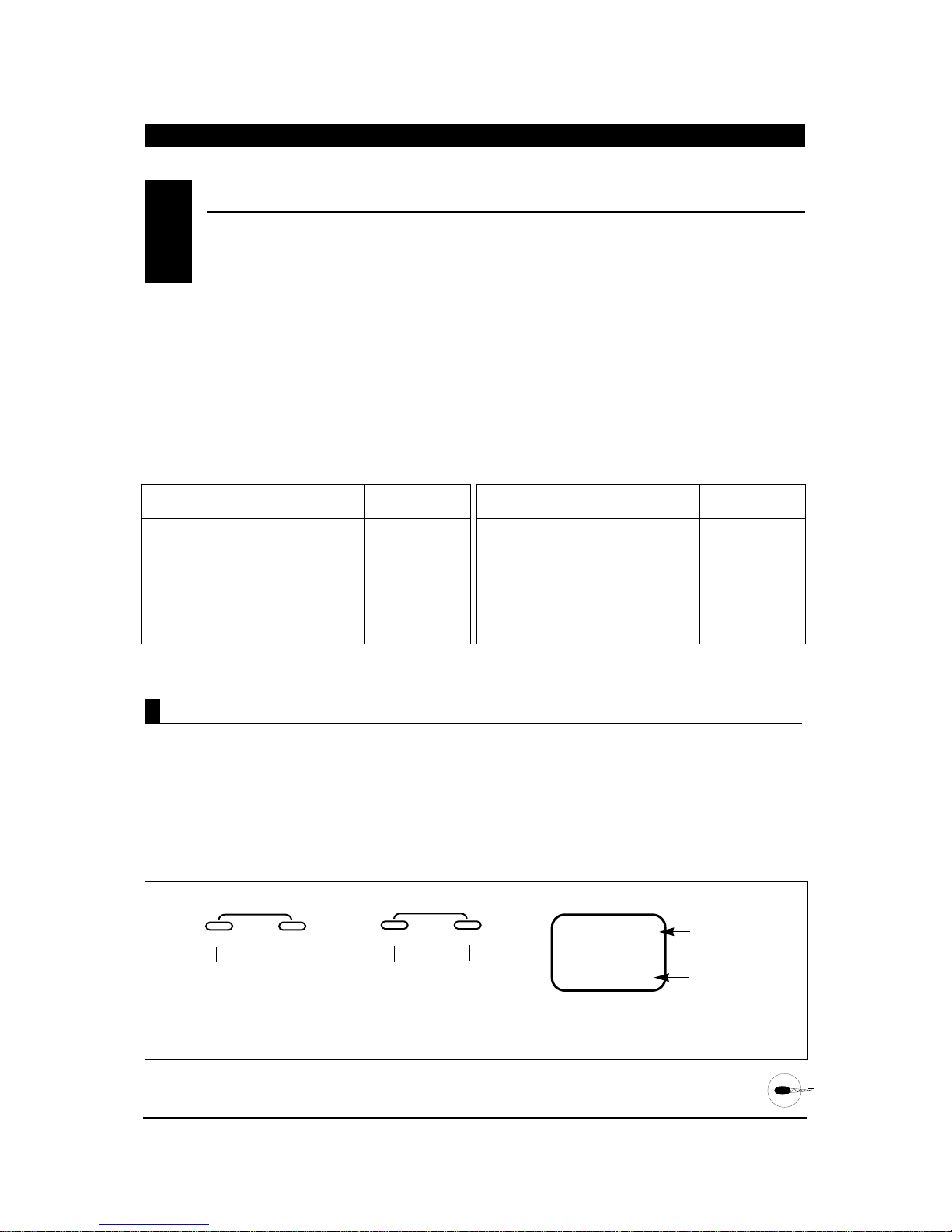
1. Press the MODE and CHANNEL buttons
simultaneously and hold.
2. Turn on the transmitter to enter the System Mode.
3. Press the MODE button until PPM appears on the
screen.
4. Press either the INCREASE or DECREASE buttons
to change the modulation to the desired setting
FM (PPM), Z-PCM (ZPC) or S-PCM (SPC).*
5. Press the MODE button to access the Model
Type Function.
6. To exit, press the MODE and CHANNEL buttons
simultaneously.
Accessing the Modulation Select Function
MODE
ENTER
CHANNEL
Press the INCREASE or
DECREASE buttons to select
the desired modulation.
Note: The modulation for the current model in use can be viewed at a
glance by pressing the mode button with the system in the normal
screen position.
CURRENT
MODULATION TYPE
I
PP
M
Press the MODE button
until PPM appears.
INCREASE
CLEAR
+–
DECREASE
CURRENT MODEL
NUMBER
MODULATION TYPES
PPM (FM)
SPCM
ZPCM
The modulation select function enables your XP652
to transmit to a variety of JR receivers that are
already, or may soon be, in existence. You can
select from either PPM (FM), Z-PCM or S-PCM,
depending on the central processing unit within your
receiver to utilize existing receivers, or to upgrade your
XP652 flight pack for future models. Your system
comes factory preset in the FM or PPM (Pulse Position
Modulation) position so that it is compatible with the
included R600 FM receiver.
Please refer to the receiver compatibility chart below
when selecting the modulation type for various JR
receivers.
Note: Once the proper modulation has been selected
for a specific model number, the modulation type will
remain the same for that model number, even during
model number/type changes. In other words, if you
have one model on FM/PPM and one model on PCM,
the system will automatically change modulation types
once the correct modulation has been selected for that
model.
MODULA TION SELECT• System Mode
6.7
Tx Modulation Compatible Receivers # of Channels &
Brief Description
PPM (FM) NER-226 6 (micro)
PPM (FM) NER-228 8
PPM (FM) NER-327x 7
PPM (FM) NER-527x 7 (micro)
PPM (FM) NER-529x 9 (micro)
PPM (FM) NER-549 9
PPM (FM) NER-600 6 (micro)
Tx Modulation Compatible Receivers # of Channels &
Brief Description
Z-PCM NER-236 6 (micro)
Z-PCM NER-627XZ or
627
“G” series
7
Z-PCM NER-J329P 9
Z-PCM NER-910XZ 10
S-PCM NER-D940S 10
S-PCM NER-649S 9
S-PCM NER-950S 10
65
XP652 MANUAL Helicopter
CHAPTER 6:FUNCTIONS • Helicopter continued
* Note: If either S-PCM or Z-PCM modulation is selected, pressing
the MODE button will access the fail-safe/hold function.
Page 66

FAIL-SAFE/HOLD FUNCTION IN Z-PCM MODULA TION (System Mode)
6.9
The Hold Function is automatically activated when
the radio is turned ON and is in the Z-PCM
modulation.
This function stops (or holds) the servos in the
positions they were in just prior to the interference.
Therefore, your airplane maintains the position held
immediately before the interference was experienced.
When a clear signal is restored, the Hold Function
releases, and control of the airplane returns to you.
If you would prefer your control surfaces to move to a
chosen position during a loss of signal, please refer to
the time delay/memory section below.
Hold (Z-PCM)
Accessing Fail-Safe/Hold (Z-PCM)
When the Fail-Safe Function is activated (i.e., when
the signal is interrupted), the transmitter
automatically moves each servo to a preset position.
The position that each servo assumes is determined
by you, as is the time length of interference that must
occur before servo movement.
After the interference has ceased, control of the
airplane returns immediately to you.
There are three time delays to choose from: 1/3 (0.3)
second, 1/2(0.5) second and 1.0 second. These time
delays are the amount of time it takes, starting the
moment the interference occurs, until the servos
assume their preset positions.
1. Press the MODE and CHANNEL button
simultaneously and hold.
2. Turn on the transmitter to enter the System
Mode.
3. Press the MODE button until FST appears on the
screen.
Note: If Fail-Safe does not appear on your LCD, it is
because you are transmitting in PPM. Fail-Safe is not
applicable in the PPM mode. Refer to the Modulation
Mode Selection Section for more information.
The Fail-Safe/Hold Function is available only when
you use the XP652 transmitter in either of the
PCM modulations — S-PCM or Z-PCM. This
function is designed to help minimize damage to
your airplane during a loss of signal to the receiver. The
servos either assume the fail-safe presets or hold the
last good signal position.
Note: In the PCM modulations, the Fail-Safe/Hold
Function cannot be totally disabled so that the servos
will react to interference in the same way as they do in
a PPM system. This is only possible with the use of a
PPM receiver and the transmitter in the PPM
modulation.
Note: Since the actual screen appearance varies,
depending on the modulation of your radio, refer
to the appropriate modulation section which follows
(Z-PCM, S-PCM).
As noted earlier, if you are in the PPM modulation, the
Fail-Safe/Hold Function is not applicable. Therefore,
the Fail-Safe/Hold Function will not appear on your
LCD in the PPM mode.
Refer to the Modulation Selection Section for more
information pertaining to the broadcast signal of your
XP652 transmitter.
FAIL-SAFE/HOLD (System Mode)
6.8
CHAPTER 6:FUNCTIONS • Helicopter continued
66
XP652 MANUAL Helicopter
Page 67
MODE
ENTER
CHANNEL
HO = ALLSERVOS HOLD
0.3 = 1/3 SECOND TIME DELAY
0.5 = 1/2 SECOND TIME DELAY
1.0 = 1 SECOND TIME DELAY
HO
FST
Press either the + or - buttons
to select the desired time delay.
INCREASE
CLEAR
+–
DECREASE
HOLD
.3 SECONDS
.5 SECONDS
1.0 SECONDS
1. After accessing the Fail-Safe Function, it is now
time to adjust the Fail-Safe Time Presets.
2. Select among the three time delays (.3, .5, or 1.0
seconds) by pressing either the + or keys until the desired setting appears on the
screen.
67
XP652 MANUAL Helicopter
CHAPTER 6:FUNCTIONS • Helicopter continued
1. Press the MODE button until FSM appears on the
screen.
Note: If Hold position is selected (HO) this
function/screen will not be present.
2. Set all controls to the desired fail-safe position,
then press the + and - buttons simultaneously. A
high pitch beep sound will confirm that the preset
positions have been entered.
3. Hold the transmitter sticks in the position that
you want the servos to assume during signal loss
conditions. You can determine fail-safe preset
positions for the other channels by placing the
potentiometers and switches in the positions that
you want them to assume during interference.
4. With the sticks, switches and potentiometers in
the fail-safe positions, press the + and - keys
simultaneously. This will enter these locations as
the fail-safe memory settings. A high pitched
beep will indicate that this setting has been
stored.
5. To confirm that the input of data was successful,
switch the transmitter OFF. The controls will move
to the input locations. If not, repeat step 4 again.
6. To exit the Fail-Safe Function, press the MODE
and CHANNEL buttons simultaneously.
Note: These preset positions remain stored in the
transmitter’s memory until both the transmitter
battery pack and the lithium back-up battery have
been removed (or until data reset has been
performed). Therefore, you do not have to reset the
fail-safe each time you fly. Should you want to readjust the fail-safe presets, access the Fail-Safe
Function and adjust the presets as you have just
done. The transmitter automatically recalls the
settings for the last fail-safe adjustment.
MODE
ENTER
CHANNEL
CL WILL FLASH WHEN FAILSAFE SERVO POSITIONS ARE
ENTERED.
C
L
FS
M
Press the + or - buttons
simultaneously to store the fail-
safe servo presets.
INCREASE
CLEAR
+–
DECREASE
FAIL-SAFE/HOLD FUNCTION IN Z-PCM MODULA TION(continued)
6.9
Setting Servo Position Presets
Setting Fail-Safe/Hold Time Delay/Memory In Z-PCM Modulation
Page 68

68
XP652 MANUAL Helicopter
CHAPTER 6:FUNCTIONS • Helicopter continued
The Hold Function is automatically activated when
the radio is turned ON and in the S-PCM modulation.
This function stops (or holds) the servos in the
positions they were in just prior to the interference.
Therefore, your aircraft maintains the position held
immediately before the interference was experienced.
When a clear signal is restored, the hold function
releases, and control of the airplane returns to you.
The XP652 allows you to combine the hold and fail-safe
presets for all six (6) channels on the receiver you can
select fail-safe or hold independently for all channels
on your aircraft. In other words, some channels will
hold their last clear signal position, while others
assume the preset position. Once the fail-safe has
been activated by signal interruption (interference), the
transmitter automatically moves the servos to a preset
position. The predetermined servo positions are set by
you. In the S-PCM fail-safe, the time delay (the amount
of time it takes, starting the moment the interference
occurs, until the servos assume the preset positions) is
fixed at .3, or 1/3, second.
After the interference has ceased, normal operation of
the airplane returns to you immediately.
Hold Function (S-PCM)
FAIL-SAFE/HOLD MEMORY IN S-PCM MODULATION (System Mode)
6.10
Fail Safe/Hold Combination in S-PCM Modulation
Page 69

1. Press the Mode button until FSM appears on the
screen.
2. Set all controls to the desired Fail-Safe positions.
Next press the + or - button simultaneously. A high
pitch beep sound will confirm that the preset
positions have been entered and accepted.
MODE
ENTER
CHANNEL
SERVO PRESET MEMORY
CL WILL FLASH WHEN FAIL SAFE SERVO POSITIONS
ARE ENTERED.
C
L
FS
M
Press the + and - buttons
simultaneously to store the
desired fail-safe presets/positions
Press the MODE and CHANNEL
buttons simultaneously to exit the
function mode
INCREASE
CLEAR
+–
DECREASE
FAIL-SAFE/HOLD MEMORY IN S-PCM MODULA TION(continued)
6.10
Setting Servo Fail-Safe Presets in S-PCM Modulation
MODE
ENTER
CHANNEL
FAILSAFE
CURRENT CHANNEL
OF = HOLD
CH = PRESET SERVO
POSITION
OF
FS2
Press the + or - buttons to activate
the preset position function
Press the channel
button to access
channels 1-6
INCREASE
CLEAR
+–
DECREASE
1. Press the MODE and CHANNEL buttons
simultaneously and hold.
2. Turn on the transmitter to enter the system mode.
3. Press the MODE button until FS1 appears on the
screen. The #1 on the screen refers to the specific
channel (1-6) to be adjusted.
4. Press the + or - button to activate (turn on) the
preset position function for that channel.
5. Press the CHANNEL button to move to the next
channel(s) to be adjusted (2-6). Repeat Step 4 for
each channel to be activated.
Note: If Hold Position (HO) is selected for all
6 channels, this Function/Screen will not be
present.
Activating Servo Fail-Safe Pre-Sets by Channel (S-PCM)
CHAPTER 6:FUNCTIONS • Helicopter continued
69
XP652 MANUAL Helicopter
Page 70
Accessing the Servo Reversing Function
THR : THROTTLE
AIL : AILERON
ELE : ELEVATOR
RUD: RUDDER
GER: GEAR/GYRO
PIT : PITCH (HE ONLY)
CHANNEL
1
2
3
4
5
6
REV◆NORM
THR
–
+
MODE
ENTER
CHANNEL INCREASE
CLEAR
DECREASE
Press the INCREASE or DECREASE
button to change the servo direction.
Press the MODE
button until
REV
◆
NORM
appears on the
screen.
Press the
CHANNEL button
until the desired
channel appears
on the screen.
Servo reversing is a very convenient function used
in the setup of a new aircraft. It is used to change
the direction of servo rotation in relation to the
corresponding stick movement. Servo reversing is
available for all 6 channels.
1. Turn on the transmitter.
2. Press the MODE and CHANNEL buttons
simultaneously to enter the function mode.
3. Press the MODE button until REV-NORM appears
on the screen.
4. Press the CHANNEL button until the desired
channel appears on the screen.
5. Press the INCREASE or DECREASE button to
change the servo direction.
6. Press the MODE button to access the dual rate
function.
7. To exit, press the MODE and CHANNEL buttons
simultaneously.
SERVO REVERSING• Function Mode
7.1
70
XP652 MANUAL Helicopter
CHAPTER 7:FUNCTIONS • Helicopter (Function Mode)
High Pitch / Throttle
Left Right
Forward
Low Pitch / Throttle
Left Stick Direction (Mode II)
Up (More Pitch)
Left (Tail Rotor)
Down (Less Pitch)
Right (Tail Rotor)
Forward
Right Stick Direction (Mode II)
Forward (Elevator)
Left (Aileron)
Back (Elevator)
Back
Right (Aileron)
Left Right
Back
Page 71
71
XP652 MANUAL Helicopter
CHAPTER 7:FUNCTIONS • Helicopter (Function Mode) continued
SWITCH POSITION (0 OR 1)
DUAL RATE VALUE (0-125%)
–
+
MODE
ENTER
CHANNEL INCREASE
CLEAR
DECREASE
Press the INCREASE or DECREASE
button to adjust the dual rate value.
Press the MODE
button until D/R
appears on the
screen.
Press the
CHANNEL button
until AI or EL
appears on the
screen.
D/R
AIO
I00
%
INDICATES THE DUAL RATE FUNCTION
CHANNEL
AI : AILERON
EL: ELEVATOR
Accessing the Dual Rate Function
Dual rate is available for the aileron and elevator
channels. The purpose of this function is to allow
for in-flight selection of two preset servo travels for
each of these channels. The amount of travel is
adjustable from 0-125%. The factory settings for both
switch positions (0 and 1) is 100%. Either position may
be selected as the low or high rate by placing the
switches in the desired position and adjusting the
value for that position. Operation of these switches is
described in Section 6.3.
Different types of maneuvers require varying amounts
of control movements. Snap rolls require large control
movements, while smooth maneuvers like long slow
rolls are best performed with smaller control
movements. Dual rates allow you to change the control
movements in flight at the flip of a switch. This allows
you to execute maneuvers requiring both radical
control movements and small control movements
during a single flight.
1. Turn on the transmitter.
2. Press the MODE and CHANNEL buttons
simultaneously to enter the function mode.
3. Press the MODE button until D/R appears on the
screen.
4. Press the CHANNEL button until the desired
channel appears on the screen (AI = aileron or
EL = elevator).
5. The number that appears directly to the right of the
selected channel is the switch position. There are
two switch positions, 0 and 1, for each of the
channels. A 0 will appear when the selected dual
rate switch is in the uppermost position and a 1
when the selected switch is in the lower position.
6. To change the switch selection you must enter the
dual rate switch selection function in the system
mode (see Section 6.3).
7. The number in the center of the screen indicates
the current dual rate value for the selected switch
position and channel. Press the INCREASE or
DECREASE button to adjust the dual rate value
(0 – 125%).
8. After adjusting the value for the 0 switch position,
change to the 1 switch position and adjust the
rates.
9. Press the CHANNEL button to select the other
channel and adjust the dual rate value for both
switch positions.
10. Press the MODE button to access the exponential
rate feature.
11. To exit, press the MODE and CHANNEL buttons
simultaneously.
DUAL RA TE• Function Mode
7.2
Page 72
72
XP652 MANUAL Helicopter
CHAPTER 7:FUNCTIONS • Helicopter (Function Mode) continued
Programmable exponential adjustments are offered
on the aileron and elevator channels of your XP652
system. Exponential is a function that allows you to
tailor the response rate of the controls as compared
to the stick inputs. The purpose of exponential is to
reduce the sensitivity in the middle portion of stick
movement, while still allowing full travel at the end of
the stick movement. In other words, the end result
(travel) remains the same, although exponential
changes the rate at which it achieves this travel.
The adjustable range of the Exponential Function is
from 0–100%. Zero percent (0%) is linear stick control
which means that the response rate is equal
throughout the stick control. One hundred percent
(100%) is full exponential. The larger the exponential
value, the less servo action, or sensitivity, you will
notice around the neutral setting.
Note: The Exponential Function operates in
conjunction with the Dual Rate Function. It is
imperative to understand the Dual Rate Function prior
to adjusting the exponential values.
Exponential may be selected independently for either
the high or low rate (position 0 or 1), or both.
EXPONENTIAL• Function Mode
7.3
Accessing the Exponential Function
1. Turn on the transmitter.
2. Press the MODE and CHANNEL buttons
simultaneously to enter the Function Mode.
3. Press the MODE button until EXP appears at the
left side of the screen.
4. Press the CHANNEL button until the desired
channel appears on the screen (AI or EL).
5. Using the appropriate dual rate switch, select the
correct position to be adjusted (0 or 1).
6. Press the + or - buttons to increase/decrease the
exponential value.
7. Press the MODE button to access the Sub-Trim
Function.
8. To exit, press the MODEand CHANNEL buttons
simultaneously.
MODE
ENTER
CHANNEL
SWITCH POSITION
AI = AILERON
EL = ELEVATOR
EXPONENTIAL VALUE
0
%
AIO
Press the + and - buttons to
increase/decrease the
exponential valve (0 - 100%)
Press the MODE
button until EXP
appears on the left
side of the screen
Note: The dual rate switch position is
changed/ accessed by setting the appropriate
dual rate switch to the 0 or 1 positions.
Press the CHANNEL
button to select either
aileron or elevator
exponential
INCREASE
CLEAR
EXP
+–
DECREASE
A GOOD STARTING
POINT FOR
EXPONENTIAL VALUE
IS APPROXIMATELY
20% – 30%.
Page 73
Accessing the Sub-T rim Function
Sub-trim is an electronic trim that is available for
each of the 6 channels. Sub-trim is particularly
useful as it allows the mechanical trim levers to be
returned to their neutral positions by adjusting
/changing the servo’s neutral position electronically,
without the need to mechanically adjust the specific
control linkage. This allows the same mechanical trim
lever settings between the five models you can control
with this radio system. Sub-trim can also allow
additional trim travel when mechanical trims do not
provide enough movement.
Note: It is recommended to use as little subtrim as
possible for adjustment. If more that 20-30 points are
required, is it suggested that a mechanical linkage
adjustment be performed.
1. Turn on the transmitter.
2. Press the MODE and CHANNEL buttons
simultaneously to enter the function mode.
3. Press the MODE button until SB-Trim appears on
the screen.
4. Press the CHANNEL button until the desired
channel appears on the screen.
5. Press the INCREASE or DECREASE button to
establish the desired amount of sub-trim.
6. Press the MODEbutton to access the TRAVEL
ADJUSTMENT function.
7. To exit, press the MODE and CHANNEL buttons
simultaneously.
SUB-TRIM• Function Mode
7.4
73
XP652 MANUAL Helicopter
CHAPTER 7:FUNCTIONS • Helicopter (Function Mode) continued
INDICATES THE
SUB-TRIM FUNCTION
SB-TRIM
THR
0
ENTER
MODE
Press the
MODE button
until SB-TRIM
appears on
the screen.
CHANNEL INCREASE
Press the
CHANNEL button
until the desired
channel appears
on the screen.
CHANNEL
THR : THROTTLE
1
AIL : AILERON
2
ELE : ELEVATOR
3
RUD: RUDDER
4
GER: GEAR/GYRO
5
PIT : PITCH (HE ONLY)
6
SUB-TRIM VALUE (±125)
CLEAR
+
Press the INCREASE or DECREASE
button to adjust the sub-trim value.
–
DECREASE
Page 74
74
XP652 MANUAL Helicopter
CHAPTER 7:FUNCTIONS • Helicopter (Function Mode) continued
TRV ADJ.
THR
+I00
%
THR : THROTTLE
AIL : AILERON
ELE : ELEVATOR
RUD: RUDDER
GER: GEAR/GYRO
PIT : PITCH (HE ONLY)
CHANNEL
1
2
3
4
5
6
INDICATES THE TRAVEL
ADJUSTMENT FUNCTION
TRAVEL ADJUSTMENT VALUE
SERVO OPERATING DIRECTION
–
+
MODE
ENTER
CHANNEL INCREASE
CLEAR
DECREASE
Press the INCREASE or DECREASE
button to adjust the travel adjustment value.
Press the
MODE button
until TRV ADJ.
appears on
the screen.
Press the
CHANNEL button
until the desired
channel appears
on the screen.
Accessing the T ravel Adjustment Function
The amount of servo travel is adjustable for each
direction for each of the 6 channels individually.
The adjustment range is from 0% to 150%. Travel
adjustment is factory set at 100% for all channels.
The travel adjustment value displayed on the screen
depends on the position of the stick or switch (e.g., flap
switch, gear switch). This function is useful either to
maximize control surface travel, or to reduce travel to
eliminate servo binding without the need for
mechanical adjustment.
This function is also used to remove unwanted
pitch-to-cyclic coupling when in CCPM Swashplate Mix
mode. Please refer to page 84 of this manual for further
information.
1. Turn on the transmitter.
2. Press the MODE and CHANNEL buttons
simultaneously to enter the function mode.
3. Press the MODE button until TRV ADJ. appears on
the screen.
4. Press the CHANNEL button until the desired
channel appears on the screen.
5. Move the selected channel stick or switch in the
direction that you want to adjust the travel. Press
the INCREASE or DECREASE button to achieve the
desired travel. Move the stick in the opposite
direction to adjust the travel in the opposite
direction.
6. The same may be done for all channels.
7. Press the MODE button to access the throttle hold
function.
8. To exit, press the MODE and CHANNEL buttons
simultaneously.
TRAVEL ADJUSTMENT• Function Mode
7.5
Page 75

Accessing the Throttle Hold Function
The throttle hold function enables the throttle
servo to be held in a specific location, while
allowing the collective pitch servo to move
independently with the throttle stick. The purpose
of this function is for practicing autorotation landings
with the helicopter’s engine at idle. When the throttle
hold switch is changed from off to activated, there will
be a third adjustable pitch curve added to the pitch
curve function. The throttle hold switch is located on
the top right rear corner of the transmitter. The throttle
hold is on in the forward position. In the back position,
the throttle hold function is off.
1. Turn on the transmitter.
2. Press the MODE and CHANNEL buttons
simultaneously to enter the function mode.
3. Press the MODE button until HLD appears on the
screen.
4. The factory setting for the throttle hold function is
off. (Note: When the throttle hold function is off,
the throttle hold pitch curve will not appear in the
pitch curve function). Press the INCREASE or
DECREASE button to activate the throttle hold
function. (The throttle hold pitch curve will now
appear in the pitch curve function). To inhibit the
throttle hold function, press the INCREASE and
DECREASE buttons simultaneously.
5. Using the INCREASE or DECREASE button, adjust
the throttle hold value to deliver a reliable engine
idle speed. To do this, set the throttle trim to your
normal starting idle setting (1/2, 3/4, etc.). Next,
with the engine off, adjust your throttle hold value
so that, when you change the throttle hold from on
to off, there is no movement of the servo arm. The
normal range of throttle hold is from -2 (1/2 trim)
to +15 (full high
trim).
6. Press the MODE button to access the pitch curve
function.
7. To exit, press the MODE and CHANNEL buttons
simultaneously.
THROTTLE HOLD• Function Mode
7.6
75
XP652 MANUAL Helicopter
CHAPTER 7:FUNCTIONS • Helicopter (Function Mode) continued
HLD
%
–5
ENTER
MODE
Press the MODE button
until HLD appears
on the screen.
CHANNEL INCREASE
INDICATES THE THROTTLE HOLD FUNCTION
HLD will flash when the throttle hold switch is on
and the function is activated.
THROTTLE HOLD VALUE (-20%–50%)
OF = OFF
CLEAR
+
Press the INCREASE or DECREASE
button to activate the throttle hold
function and to adjust the value.
–
DECREASE
Page 76
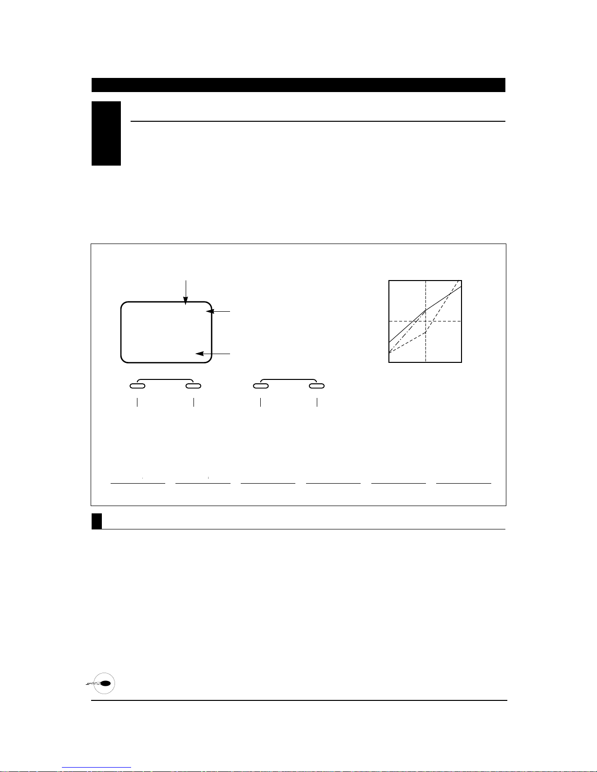
CHAPTER 7:FUNCTIONS • Helicopter (Function Mode) continued
76
XP652 MANUAL Helicopter
Accessing the Pitch Curve Function
L
LOW
0%
The XP652 offers 3 separate pitch curves with 3
adjustable reference points per curve. This function
allocates a separate pitch curve setting during
normal, stunt, and throttle hold modes to
maximize flight performance. Once the pitch curves are
established, each can be activated in flight using the
2-position flight mode switch and the throttle hold
switch.
Each of the 3 reference points of the pitch curve are
independently adjustable from 0–100%. These 3 points
correspond to the low, middle, and high positions of
the throttle stick (collective).
The graph below shows samples of pitch curves in the
normal (N), stunt (S) and throttle hold (H) conditions.
The factory preset values for all 3 pitch curves are:
Low 0%, Middle 50%, and High
100%.
1. Turn on the transmitter.
2. Press the MODE and CHANNEL buttons
simultaneously to enter the function mode.
3. Press the MODE button until PLN appears on the
screen. The letter to the far right indicates the
specific pitch curve section that you are in (N, S or
H). The letter in the center indicates the reference
point that you are in (L, 2 or H).
4. Press the CHANNEL button to select the reference
point of the pitch curve you want to change.
5. Press the INCREASE or DECREASE button to
change the value of the current reference point. The
range of each point is 0–100% in 1% intervals.
6. To set the pitch curve for the stunt (flight) mode,
press the MODE button once. Then, repeat Steps 5
and 6 to adjust.
7. To set the pitch curve for the throttle hold mode,
press the MODE button once. Then, repeat Steps 5
and 6 to adjust.
8. Press the mode button to access the throttle curve
function.
Note: If throttle hold is not activated, the throttle
curve function will be accessed.
9. To exit, press the MODE and CHANNEL buttons
simultaneously.
PITCH CURVE• Function Mode
7.7
N
N
N N
:
ODE
e MODE
until PLN
rs on the
. Press
o access
hold or
e curve.
ENTER
Press the MODE
button until PLN
appears on the
again to access
2 : CENTER 50%
H: HIGH 100%
POINT DISPLAY/STICK POSITION
L : LOW 0%
2 : CENTER 50%
H: HIGH 100%
PLN
PLN
%
0
0
ENTER
CHANNEL INCREASE
MODE
Press the
CHANNEL button
to select the
screen. Press
desired point
display/stick
stunt, hold or
position.
throttle curve.
CHANNEL INCREASE
Press the
CHANNEL button
to select the
desired point
display/stick
position.
SWITCH POSITION
Flashing when switch position
and display are the same.
N: NORMAL
S: STUNT
H: HOLD
%
PITCH CURVE VALUE (0-100%)
SWITCH POSITION
Flashing when switch position
and display are the same.
N: NORMAL
S: STUNT
Only visible when hold
H: HOLD
function is activated.
Press the INCREASE or DECREASE
button to adjust the pitch curve value.
Only visible when hold
function is activated.
PITCH CURVE VALUE (0-100%)
CLEAR
+
+
Press the INCREASE or DECREASE
button to adjust the pitch curve value.
–
CLEAR
DECREASE
–
DECREASE
NORMAL
HOLD
STUNT
L
2
THROTTLE/PITCH
STICK LOCATION
100%
H
50%
0%
OUTPUT VALUE
PLN
PITCH CURVE
LOW STICK
NORMAL MODE
P2N
PITCH CURVE
HALF STICK
NORMAL MODE
PHN
PITCH CURVE
HIGH STICK
NORMAL MODE
PLS
PITCH CURVE
LOW STICK
STUNT MODE
P2S
PITCH CURVE
HALF STICK
STUNT MODE
PHS
PITCH CURVE
HIGH STICK STUNT
MODE
Page 77
Accessing the Throttle Curve Function
Adjustment of the throttle curve is very similar to
the pitch curve adjustment described in the
preceding section. A thorough understanding of the
pitch curve section will make the throttle curve
section easier to understand.
There are two independent types of throttle curves
available — normal and stunt. The normal, or hover,
throttle curve has 3 reference points (L,2, H) and the
stunt, or flight, throttle curve has 2 reference points
(L, 2).
The two throttle curves are activated by the flight mode
switch located on the top left rear corner of the
transmitter. The throttle curve is in the normal
condition when the flight mode switch is in the back
position. The throttle curve is in the stunt condition
when the flight mode switch is in the forward position.
Note: In stunt mode (S), the high position of the
throttle curve is preset to 100%, and is not adjustable.
1. Turn on the transmitter.
2. Press the MODE and CHANNEL buttons
simultaneously to enter the function mode.
3. Press the MODE button until TLN appears on the
screen. The letter to the far right indicates the
specific throttle curve section that you are in (N, S
or H). The letter in the center indicates the
reference point that you are in.
4. Press the CHANNEL button to select the reference
point of the throttle curve you want to change (L, 2 or
H*).
5. Press the INCREASE or DECREASE button to
change the value of the current reference point. The
range of each point is 0–100% in 1% intervals.
6. To set the throttle curve for the stunt (flight) mode,
press the MODE button once. Then, repeat Steps 5
and 6 to adjust.
7. Press the MODE button once to access the
revolution mixing function.
8. To exit, press the MODE and CHANNEL buttons
simultaneously.
* Normal mode only.
THROTTLE CURVE• Function Mode
7.8
77
XP652 MANUAL Helicopter
CHAPTER 7:FUNCTIONS • Helicopter (Function Mode) continued
–
+
MODE
ENTER
CHANNEL INCREASE
CLEAR
DECREASE
Press the INCREASE or DECREASE
button to adjust the throttle curve value.
Press the MODE
button until TLN
appears on the
screen. Press
again to access
stunt mode.
Press the
CHANNEL button
to select the
desired point
display/stick
position.
THROTTLE CURVE VALUE (0-100%)
TLN
0
%
SWITCH POSITION
Flashing when switch position
and display are the same.
N: NORMAL
S: STUNT
H: HOLD
Only visible when the hold
function is activated.
POINT DISPLAY/STICK POSITION
L : LOW 0%
2 : CENTER 50%
H: HIGH 100%
N
Page 78
78
XP652 MANUAL Helicopter
CHAPTER 7:FUNCTIONS • Helicopter (Function Mode) continued
The revolution mixing function combines tail rotor
input with the throttle/collective function to
counteract the torque created by the main rotor
blades. When properly adjusted, the helicopter will
climb and descend without a tendency to yaw in either
direction.
Since the torque created by the main rotor blades
varies with different throttle/pitch settings, it is
necessary for the tail rotor blades to change pitch at
the same time. The “U” or up mixing adjusts the tail
rotor compensation from the mid to high throttle stick
setting. The “D” or down mixing adjusts the tail rotor
compensation from the mid to the low throttle stick
setting.
Thus, if you were to move the throttle from the low to
high positions, the tail rotor servo will move from the
“D” to the “U” settings.
Revolution Mixing Set-up Procedure
First, set up the helicopter so that it will maintain a
stable hover with the tail rotor trim in the center
position. Next, bring the helicopter into a steady
vertical climb. The body of the helicopter will move in
the opposite direction to the main rotor rotation.
Increase the “U” or up mixing until the helicopter
climbs without the tendency to rotate. At a safe
altitude, reduce the throttle. The helicopter will
descend, and the body will turn in the same direction
as the main rotor blades. Increase the “D” or down
mixing until the helicopter descends without the
tendency to rotate.
1. Turn on the transmitter.
2. Press the MODE and CHANNEL buttons
simultaneously to enter the function mode.
3. Press the MODE button until RVU appears on the
screen.
4. Press the CHANNEL button to select the up or
down mixing function.
5. Press the INCREASEor DECREASE button to
adjust the mixing value of the applicable function.
Press the INCREASE and DECREASE buttons
simultaneously to reset the mixing value to 0%. To
change the mixing direction, press the INCREASE
and DECREASE buttons simultaneously again.
6. Press the MODE button to access the RUDDER
OFFSET function.
7. To exit, press the MODE and CHANNEL buttons
simultaneously.
Accessing the Revolution Mixing Function
REVOLUTION MIXING• Function Mode
7.9
V
MIX
–0
INDICATES THE
REVOLUTION MIXING FUNCTION
RVU
%
MIXING FUNCTION
U = UP Flashing when throttle/pitch
stick is in the up position.
D = DOWN Flashing when throttle/pitch
stick is in the down position.
REVOLUTION MIXING VALUE (0-125%)
MIXING DIRECTION
– = RIGHT MIXING
+ = LEFT MIXING
ENTER
MODE
Press the MODE
button until RVU
appears on the
screen.
CHANNEL INCREASE
Press the
CHANNEL button
to select the up or
down mixing
function.
Press the INCREASE and
DECREASE buttons simultaneously to
change the mixing direction.
CLEAR
+
Press the INCREASE or DECREASE
button to adjust the revolution mixing value.
–
DECREASE
Page 79
Accessing the Rudder Offset Function
When the throttle hold switch is on (during
autorotations), the revolution mixing feature
becomes inactive. The rudder offset function is
designed to automatically change the tail blade
pitch when the throttle hold switch is on, providing a
straight descent during autorotations. The adjustable
range of the rudder offset is L125 – 0 – R125. This
feature is only applicable for helicopters using a
“driven” or “limited slip” type tail rotor system during
autorotations.
1. Turn on the transmitter.
2. Press the MODE and CHANNEL buttons
simultaneously to enter the function mode.
3. Press the MODE button until RVU appears on the
screen.
4. Press the CHANNEL button until HLD appears on
the screen.
5. From the 0 offset, press the DECREASE button to
enter a right offset value or the INCREASE button
to enter a left offset value. To reset the rudder
offset value, press the INCREASE and DECREASE
buttons simultaneously.
6. Press the MODE button to access the program mix
A function.
7. To exit, press the MODE and CHANNEL buttons
simultaneously.
RUDDER OFFSET• Function Mode
7.10
79
XP652 MANUAL Helicopter
CHAPTER 7:FUNCTIONS • Helicopter (Function Mode) continued
OFFSET
HLD
0
ENTER
MODE
Press the MODE
button until RVU
appears on the
screen.
CHANNEL INCREASE
Press the
CHANNEL button
until HLD appears
on the screen.
INDICATES THE RUDDER
OFFSET FUNCTION
RUDDER OFFSET POSITION
(MAXIMUM ±125)
Press the INCREASE and
DECREASE buttons simultaneously to
reset the rudder offset value.
CLEAR
+
Press the
INCREASE
button to adjust
the left offset
value.
–
DECREASE
Press the
DECREASE
button to adjust
the right offset
value.
Page 80
The XP652 in helicopter mode offers one (1)
programmable mix to be used for a number of
different purposes. The functions allow mixing any
one channel to any other channel.
The mix can remain ON at all times, or be switched
OFF in flight using a number of different switches.
(Refer to Chart A). Each channel is identified by
channel numbers 1-6 (i.e., 2 = aileron, 4 = rudder, etc.
— see Chart B) The channel appearing first is known
as the “master channel,” or the channel to which you
want to mix. The second channel is known as the
“slave channel,” or the channel that is being mixed
into the master channel. For example, ELEV-AILE
would indicate elevator to aileron mixing each time
the elevator stick is moved, the elevator will deflect,
and the aileron will automatically move in the
direction and to the value input. Mixing is
proportional, so small inputs of the master channel
will produce small outputs of the slave channel. Each
programmable mix has a mixing “offset.” The purpose
of the mixing offset is to redefine the neutral position
of the slave channel.
The Elevator-Aileron mix mentioned above is most
commonly used to help trim the helicopter for proper
“loop tracking.” This type of mix should be used only
by pilots who are comfortable with their programming
abilities with the XP652.
PROGRAMMABLE MIXING (A)• Function Mode
7.11
Accessing the Programmable Mixing Function
1. Turn on the transmitter
2. Press the + and - buttons simultaneously to enter
the Function Mode
3. Press the MODE button until MIX A11 appears at
the top right corner of the screen. This is program
mix A.
MIX A
ON
F1
FO
H
Chart A Switch Selection
SWITCH
Always ON
Flight Mode Switch
Position 1 ON
Flight Mode Switch
Position O ON
Throttle Hold Switch
FUNCTION
Throttle
Aileron
Elevator
Rudder
Gear
Pitch
(AUX1)
Chart B Channel Numbers
CHANNEL NUMBER
1
2
3
4
5
6
MODE
ENTER
CHANNEL
0
%
AII
Press the MODE button until
MIX A11 appears
INCREASE
CLEAR
MIX
+–
DECREASE
CHAPTER 7:FUNCTIONS • Helicopter (Function Mode) continued
80
XP652 MANUAL Helicopter
CURRENT MIX CHANNELS
Page 81
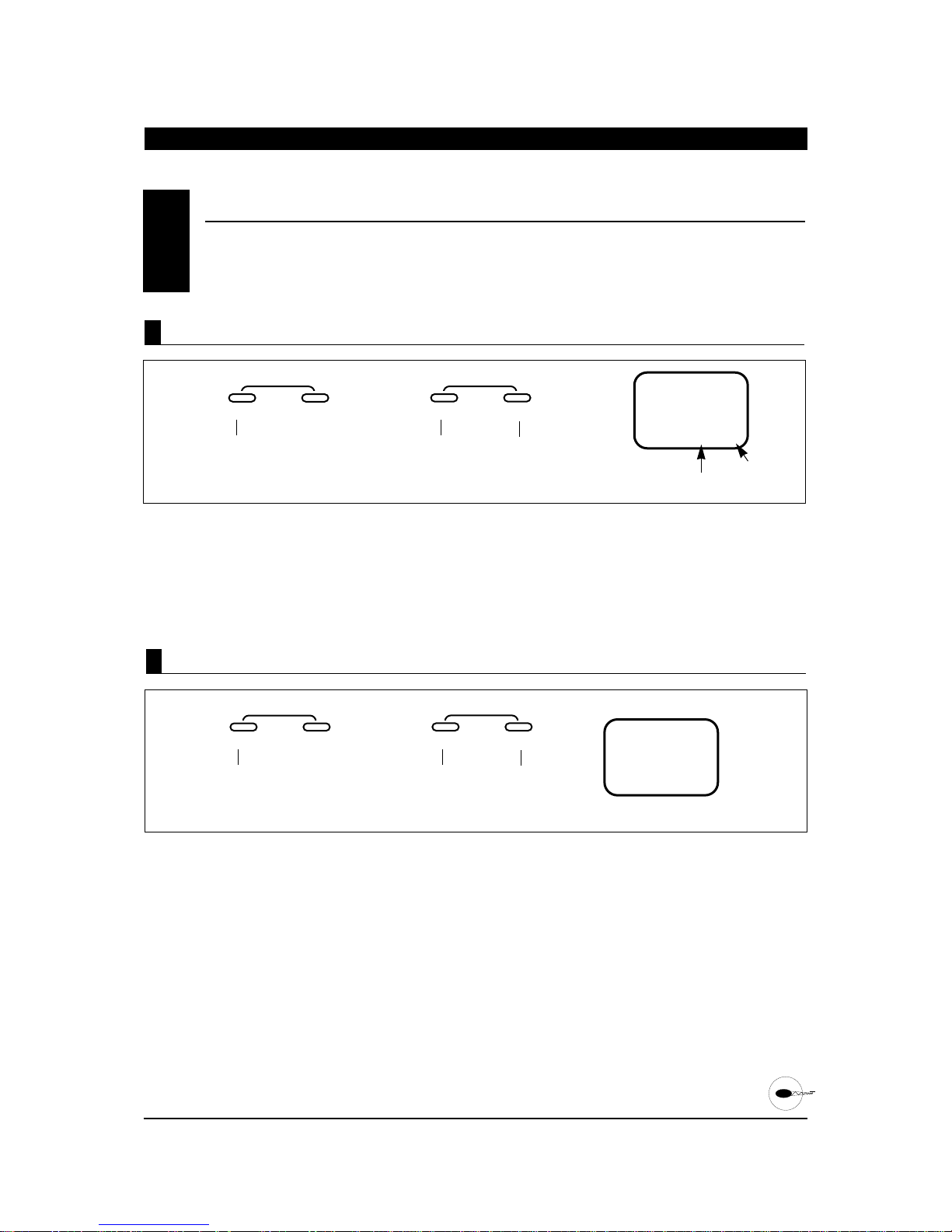
81
XP652 MANUAL Helicopter
CHAPTER 7:FUNCTIONS • Helicopter (Function Mode)
continued
1. Press the Channel button once until MIX ASW
appears.
2. Press the + or - button to select the desired switch
to be used to activate the mixing, or leave as ON if
a constant mix is desired.
(Refer to Chart A on the preceding page for possible
mix/switch selections.)
1. Press the CHANNELbutton twice until MIX A CH
appears on the screen.
2. Press the + button to select the desired
“
Master
Channel” (1-6).
3. Press the - button to select the desired “slave
channel” (1-6). Refer to Chart B on the preceding page
for channel number clarification.
PROGRAMMABLE MIXING (A)• Function Mode (continued)
7.11
MODE
ENTER
CHANNEL
32
ACH
Press the CHANNEL button
until MIX ACH appears.
Press to select
“Master”
channel desired.
Press to select
“Slave”
channel desired.
MASTER
CHANNEL
SLAVE
CHANNEL
INCREASE
CLEAR
MIX
+–
DECREASE
Assigning Channels
MODE
ENTER
CHANNEL
O
N
A5W
Press the CHANNEL button
until MIX ASW appears.
Press the + or - buttons to select
the desired switch to be activated
(refer to Chart Aon preceding page)
SWITCH
CHOICES
ON
F1
FO
H
INCREASE
CLEAR
MIX
+–
DECREASE
Switch Selection
Page 82
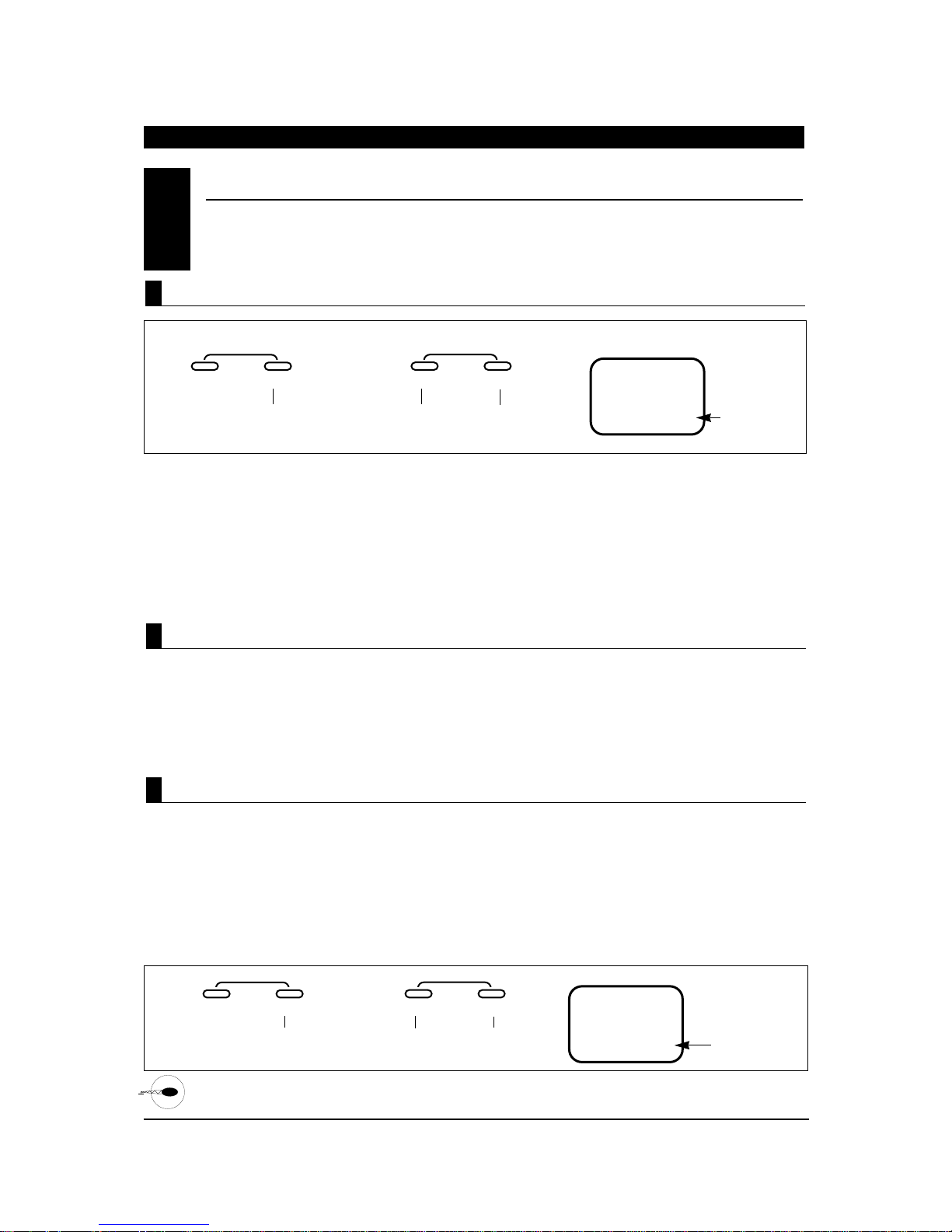
1. Press the CHANNEL button once until MIX A
appears, with the mixing value located at the
bottom of the screen.
2. To set the slave channels mixing valve, move and
hold the master channel control stick to the
direction to be adjusted (up/down — left/right),
then press the + key to add + mixing value, or the
– key to add – mixing value (+/–125%). When the
master channels stick is moved, the display will
automatically show the mixing valve for the
current stick direction.
Note: If a mix switch position other than ON is
selected, it will be necessary to move the selected
switch to the ON, or active, position to adjust the
mixing value. OF will appear on the screen if the
selected mixing switch is in the off position.
The purpose of the mixing offset feature is to redefine
the neutral position of the slave channel to be mixed.
Any desired position may be selected for the offset
reference point. To set the offset position, place the
master channel’s stick to the desired position and
press either the + or - keys.
This position is now stored in the memory and its
offset value from the neutral position of the master
channel is indicated numerically on the LCD display.
Then, the mixing value at the determined offset
position is now set at 0.
1. Press the CHANNEL button once until offset
appears in the center of the screen.
2. Place the master channel stick to the desired
position of slave channel offset, then press either
the + or - button to store.
3. Press the MODE button once to access the stunt
trim function.
4. To exit the Function Mode, press the MODEand
CHANNEL buttons simultaneously.
Note: If a mix switch position other than ON has been
selected, it will be necessary to move the selected
switch to the ON or active position to set the offset
value. OF will appear on the screen if the selected
mixing switch is in the OFF position.
PROGRAMMABLE MIXING (A)• Function Mode (continued)
7.11
MODE
ENTER
CHANNEL
0
%
A32
Press the channel button
once until MIX Aand
value % appears
Press either the + or - buttons to
increase/decrease mixing valve.
CURRENT
MIXING
VALUE
INCREASE
CLEAR
MIX
+–
DECREASE
MODE
ENTER
CHANNEL
0
A32
Press the CHANNEL
button until OFFSET
appears on the screen.
Press either the + or - buttons to
slave the offset position.
OFFSET
MIXING
VALUE
INCREASE
CLEAR
MIX
OFFSET
+–
DECREASE
Mixing Value Adjustment
Mixing Offset Adjustment
Accessing the Offset Function
CHAPTER 7:FUNCTIONS • Helicopter (Function Mode) continued
82
XP652 MANUAL Helicopter
Page 83
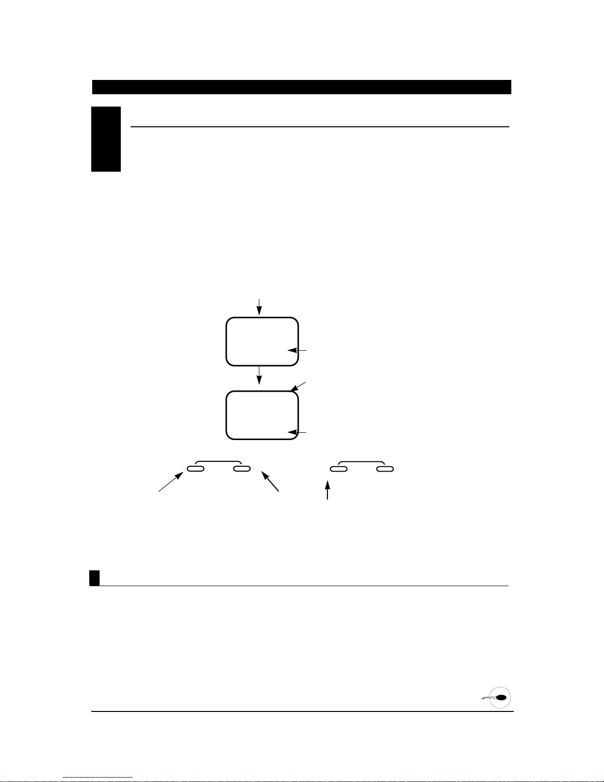
The Stunt Trim Function is a trim position setting for
aileron, elevator and rudder for use during forward
flight maneuvers. This function is activated when in
the Flight Mode 1 position only.
Note: When this function is activated, the trim levers
of the aileron, elevator and rudder are inactive. The
maximum adjustment range is approximately 30
degrees.
To adjust the stunt trim, fly your helicopter in a
straight line at full throttle/pitch in Flight Mode 1.
Center the elevator stick. Note which direction the
helicopter pitches. If the helicopter pitches up, land
the model and add down stunt trim. Repeat until no
pitching occurs.
Next, check the rudder. Add rudder stunt trim until
the tail tracks directly behind the helicopter. Finally,
adjust the aileron stunt trim in the same manner
until no rolling occurs. When properly adjusted, your
helicopter will fly straight and level at full speed with
no correction or trim required.
STUNT TRIM• Function Mode
7.12
Accessing the Stunt Trim Function
CHAPTER 7:FUNCTIONS • Helicopter (Function Mode) continued
83
XP652 MANUAL Helicopter
OF
STT
O
ST2
The screen is
visible only when
“ON” has been
selected
Current setting
OF = Off
ON = On (Active)
Indicates current channel
to be adjusted
2 = Aileron
3 = Elevator
4 = Rudder
Indicates Current Trim Value ( 125)
Indicates Stunt Trim Function
MODE
ENTER
CHANNEL
Press the MODE
button until STT
appears on the
screen.
Press the INCREASE key to
activate the Stunt Trim Fuction
(ON).
Press the INCREASE or
DECREASE buttons to adjust
the stunt trim value for each
channel.
Once the stunt trim
“ON” position has
been selected, press
the CHANNEL key to
select the desired
channel number to
be adjusted.
INCREASE
CLEAR
+–
DECREASE
1. Trim on the transmitter.
2. Press the MODE and CHANNEL buttons simultaneously
to enter the Function Mode.
3. Press the MODE button until STT appears on the screen.
4. Press the increase button once to activate the Stunt Trim
Function. “ST2” will appear on the screen, indicating that
the stunt trim function is now “on.”
5. Press the channel button to select the desired channel
number to be adjusted.
6. Press the INCREASE or DECREASE buttons to select the
desired trim value for each channel ( 125).
7. Press the MODE button once to access the CCPM
Swashplate Mix Function.
8. To exit, press the MODEand CHANNEL
buttons simultaneously.
+
-
+
-
Page 84
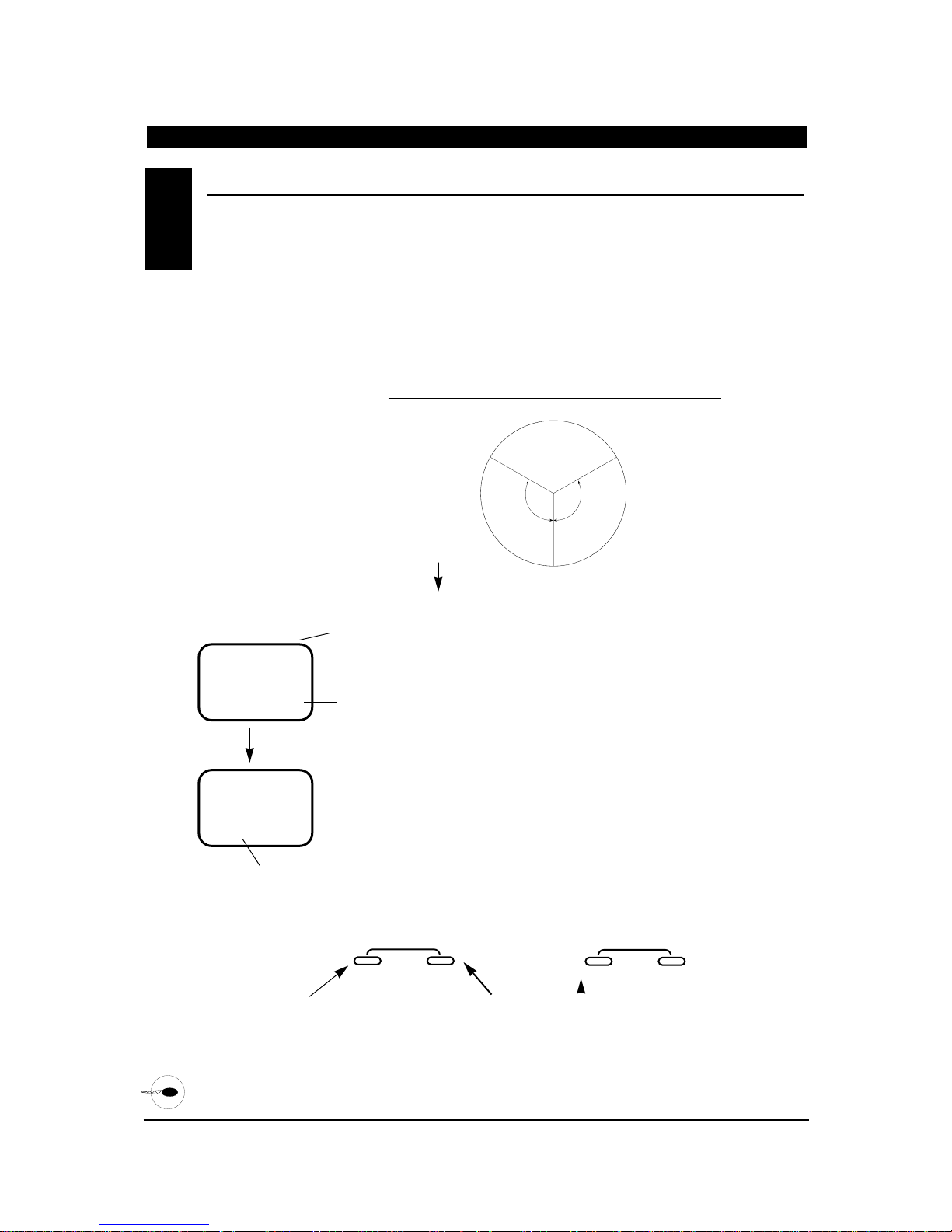
84
XP652 MANUAL Helicopter
CCPM SWASHPLA TE MIXING• Function Mode
7.13
CHAPTER 7:FUNCTIONS • Helicopter (Function Mode) continued
The CCPM Swashplate Mixing Function (Cyclic
Collective Pitch Mixing) of the XP652 system is
designed to allow the XP652 to be used in model
helicopters that utilize a 120° CCPM-type swashplate
control system. CCPM is a type of pitch mixing where
the three servos are connected directly to the
swashplate of the helicopter and physically move both
in unison and independently for all changes in
pitch/cyclic. Please refer to the diagram below for
proper 120° three servo CCPM identification and
connection.
3 Servos (120 degrees) CCPM Mixing
Front of
Helicopter
Note: The CCPM Swashplate
Mixing Function is designed for
use
only with helicopters that
incoorporate the special 120°
three servo CCPM control system
design.
Use of the CCPM Function in a
non-CCPM-equipped model can
result in an uncontrollable
condition.
OF
CCP
Indicates CCPM Swashplate
Mixing Function
Indicates current condition:
OF = Off
ON = On
Indicates current CCPM mix
value ( 100)
Indicates current channel:
2 = Aileron
3 = Elevator
6 = Pitch
MIX
+60%
CP2
MIX
Please refer to the helicopter manufacturer’s instructions
for proper mixing values.Please also note that if control
system interaction exists (pitch to aileron, pitch to
elevator movement, etc.), it will be necessary to alter the
travel adjust values for channels 2, 3, and 6 to correct this
situation. Please refer to page 74 of this manual for
further information.
MODE
ENTER
CHANNEL
Press the MODE
button until CCP
appears on the
screen.
Press the INCREASE key to
activate the CCPM Swashplate
Function (ON).
Press the INCREASE or
DECREASE buttons to adjust
the CCPM mix value for each
channel.
Once the CCPM
“ON” position has
been selected, press
the CHANNEL key to
select the desired
channel number to
be adjusted.
INCREASE
CLEAR
+–
DECREASE
+
-
Ch. 6 Pitch
Fore/Aft
Ch. 2 Aileron
120° 120°
Ch. 3 Elevator
3 Servos – 120° Type
Page 85
85
XP652 MANUAL Helicopter
CCPM SWASHPLA TE MIXING• Function Mode (continued)
7.13
CHAPTER 7:FUNCTIONS • Helicopter (Function Mode) continued
Accessing the CCPM Swashplate Mixing Function
1. Turn on the transmitter
2. Press the MODE and CHANNEL buttons simultaneously
to enter the Function Mode.
3. Press the MODE button until CCP appears on the screen.
4. Press the INCREASE button once to activate the CCPM
Swashplate Mix Function. The screen will then move to
the “CP2” screen, indicating that the CCPM function is
now “on.”
5. Press the CHANNEL button to select the desired channel
number to be adjusted.
6. Press the INCREASE or DECREASE buttons to select the
desired mixing value for each channel ( 100).
7. Press the MODE button once to access the Trim Offset
Value Function.
8. To exit, press the MODEand CHANNEL buttons
simultaneously.
+
-
Page 86
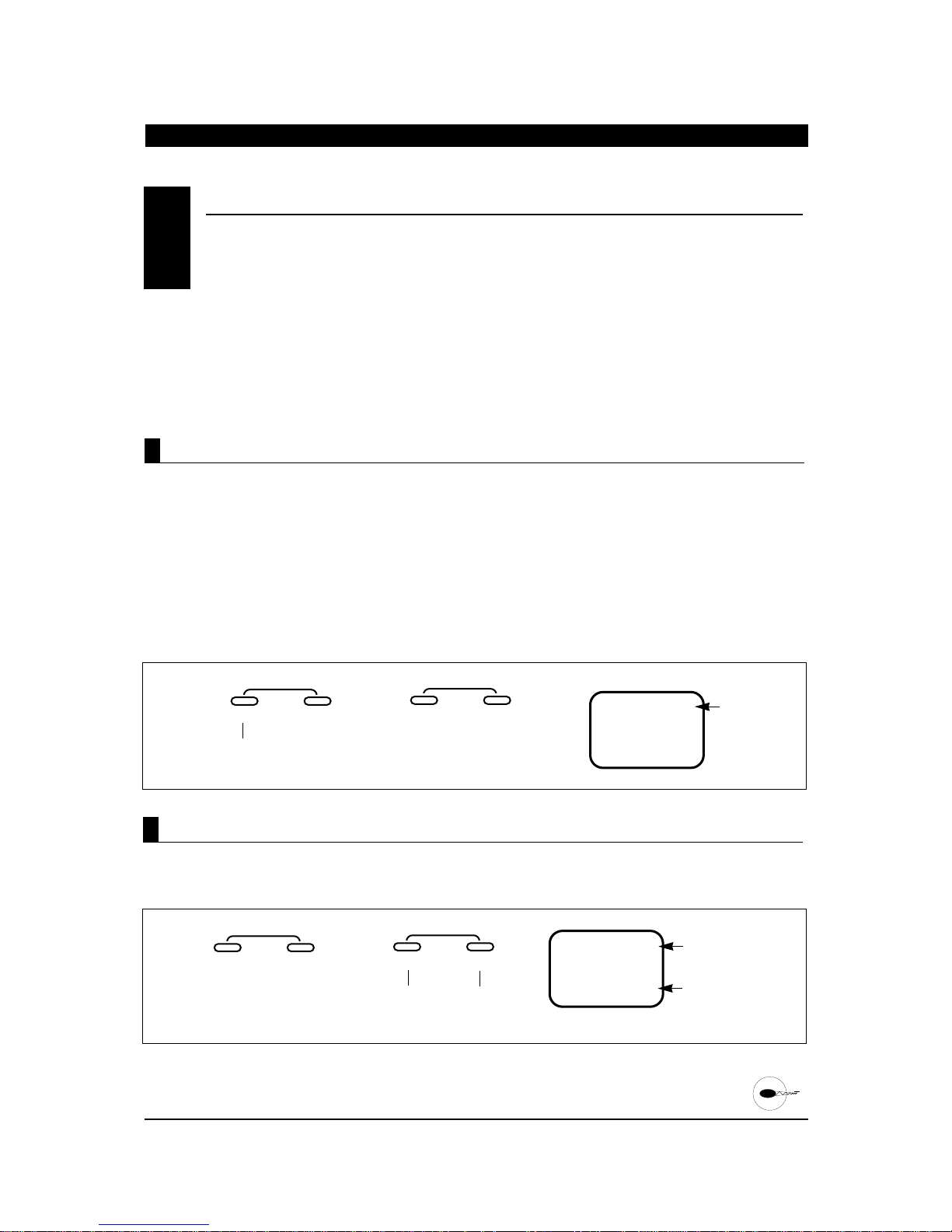
The Trim Offset Memory Function of your XP652
allows you to test fly your aircraft and correct for
any built-in trim requirements. After you adjust the
aileron, elevator and/or rudder trim levers during
the test flights, the trim levers are no longer in their
center, or neutral, positions. The use of trim offset
allows you to return the trims to their center, or
neutral, positions without readjusting the control
surface linkages mechanically.
This function is very useful when switching from model
to model. It allows your trims to remain in their
neutral positions while retaining their corrections.
Using this feature, you can easily switch among the
five (5) model memories without the need to readjust
for each aircraft’s individual trim requirements.
Note: In helicopter mode, the trim offset memory
values stored will alter the servo position in both
normal and stunt modes. Separate adjustments each
mode is not possible, except through the stunt trim
function (page 83).
1. First, test fly your aircraft and adjust the aileron,
elevator and/or rudder trim levers. After all
adjustments have been made, land your
helicopter. DO NOT adjust/reposition any of the
trim levers at this time.
CAUTION: Do not attempt to adjust the Trim Offset
Memory Function while your model’s engine is
running. Please stop your aircraft’s engine before
entering the Function Mode.
2. Turn on the transmitter.
3. Press the MODE and CHANNEL buttons
simultaneously to enter the Function Mode.
4. Press the MODE button until TRM offset appears
on the screen.
TRIM OFFSET MEMORY
7.14
Accessing the T rim Offset Memory Function
MODE
ENTER
CHANNEL
TR
M
Press the MODE button
until TRM OFFSET
appears on the screen.
TRM-TRIM
OFFSET
INCREASE
CLEAR
OFFSET
+–
DECREASE
A.
MODE
ENTER
CHANNEL
+C
L
MOV
Press the + or - buttons; MOV
+CL should appear on the screen
MOVE TRIM LEVERS
TO THEIR CENTER/
NEUTRAL POSITIONS
PRESS THE + AND BUTTONS
SIMULTANEOUSLY
TO STORE
INCREASE
CLEAR
OFFSET
+–
DECREASE
B.
5. Press the + or - buttons. MOV + CL should appear
on the screen.
Accessing the T rim Offset Memory Function
CHAPTER 7:TRIM OFFSET MEMORY • Helicopter continued
86
XP652 MANUAL Helicopter
Page 87
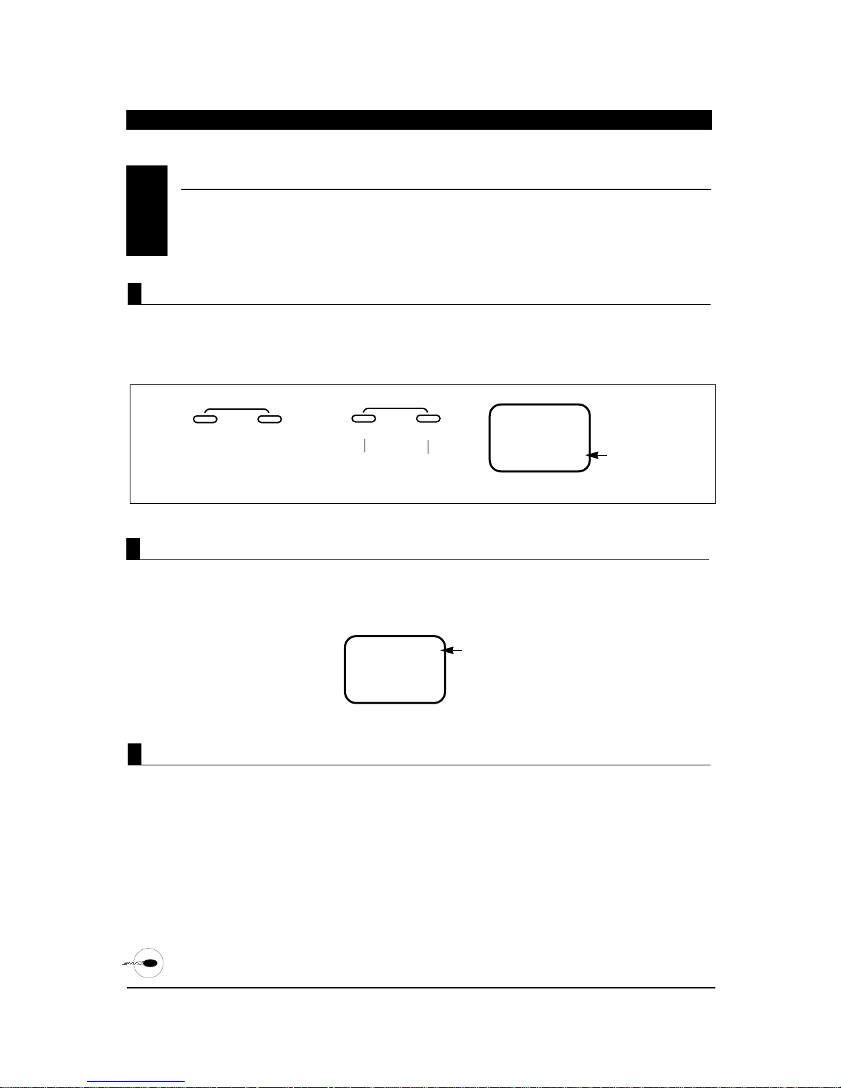
TRIM OFFSET MEMORY (continued)
7.14
6. Move all trim levers to their center positions, then
press the + or - keys simultaneously to store the trim
offsets. The screen should appear as shown:
7. Press the MODE and CHANNEL buttons
simultaneously to exit the function mode.
Accessing the T rim Offset Memory Function (continued)
If OVR appears on the screen when the trim levers are
moved to their center positions, this indicates that the
amount of offset trim for one or more channels is in
excess of the acceptable limits. If this situation occurs,
a mechanical adjustment of the control linkage will be
necessary.
Over T rim
MODE
ENTER
CHANNEL
TR
M
Press the + or - buttons
simultaneously to store the
trim offset.
OFFSET FUNCTION
MEMORIZED/
COMPLETE
INCREASE
CLEAR
OFFSET
+–
DECREASE
C.
--
OVR
TRIM VALUE EXCEEDS
ACCEPTABLE LIMITS(over)
LINKAGE ADJUSTMENT
NECCESSARY
OFFSET
This feature is useful if you wish to clear all trim offset
stored within the XP652’s memory without affecting
the data stored for other functions. The most common
use for this feature is if you have disassembled/
repaired your model and would like to return all
servos/trims to their “true neutral” positions before
linkage installation/initial test flights.
Clearing T rim Offset Memory
CHAPTER 7:TRIM OFFSET MEMORY • Helicopter continued
87
XP652 MANUAL Helicopter
Page 88
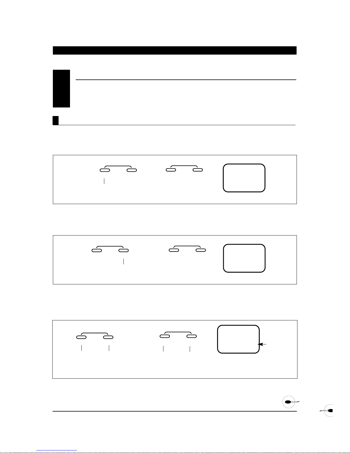
TRIM OFFSET MEMORY (continued)
7.14
MODE
ENTER
CHANNEL
TR
M
Press the MODE button until
TRM OFFSET appears on
the screen.
INCREASE
CLEAR
OFFSET
+–
DECREASE
A.
MODE
ENTER
CHANNEL
C
L
M
OV
Press the CHANNEL button
once until CL appears on
the screen.
CL = Clear
Trim Offset
INCREASE
CLEAR
OFFSET
+–
DECREASE
B.
MODE
ENTER
CHANNEL
0
TR
M
Press the MODE and CHANNEL buttons
simultaneously to exit the function mode.
INDICATES
THATALL
TRIM OFFSET
MEMORY
VALUES ARE
SET TO 0%
(NEUTRAL)
INCREASE
CLEAR
OFFSET
+–
DECREASE
Press the + and - buttons simultaneously to
reset the offset trim valves to 0% (neutral).
C.
1. Turn on the transmitter
2. Press the MODE and CHANNEL buttons
simultaneously to enter the Function Mode.
3. Press the MODE button until TRM OFFSET appears
on the screen.
4. Press the CHANNEL button once; CL should
appear at the bottom of the screen:
5. Press the + and - keys simultaneously .0 should
appear on the screen indicating that the offset trim
memory has been reset to 0, or neutral trim.
6. Press the MODE and CHANNEL buttons
simultaneously to exit the function mode.
Accessing the Offset T rim Clear Function
88
XP652 MANUAL Helicopter
CHAPTER 7:TRIM OFFSET MEMORY • Helicopter continued
Page 89
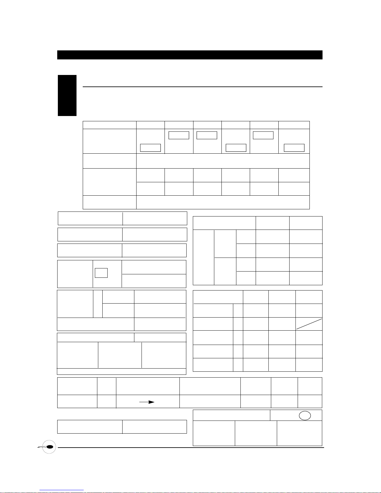
D/R % %
EXP % %
D/R % %
EXP % %
89
XP652 MANUAL Helicopter
CHAPTER 8:DAT A SHEETS
•
XP6452 Helicopter
ERGO .32/.46 (INITIAL SETUP)8.1
TRIM OFFSET
CHANNEL THR (1) AIL (2) ELE (3) RUD (4) GER (5) PITCH (6)
NORM NORM NORM NORM NORM NORM
••••• •
REV REV REV REV REV REV
SUB-TRIM Adjust so that no trim is required
TRAVEL ADJUST + % + % + % + % + %
(TRV ADJ.) - % - % - % - % - %
FAIL-SAFE (S-PCM) Adjust only if S-PCM modulation is selected
80 80 100 100 150
80 80 100 100 150
90 90
20 20
100 100
20 20
0 50 100
40 50
Adjust for
full power
Adjust only if Z-PCM
modulation is selected
Store trim positions after
initial test flight
Factory Pre-Sets
Factory Pre-Sets
Adjust for idle
35
35
Adjust for
engine off
REVERSE SW
*
* Note: Before flying, confirm that all controls
function in their proper direction.
FAIL-SAFE TIME (ZPCM)
AILE (AI) ELEV (EL)
POS O
POS 1
L 2 H
N
S
N
S
H
THRO CURVE
TLN, T2N, THN,
TLS, T2S
PITCH CURVE
PLN, P2N, PHN,
PLS, P2S, PHS,
PLH, P2H, PHH
% % %
% %
-2° pitch 5° pitch 10°pitch
-5° pitch 5° pitch 8.5° pitch
-5° pitch 5° pitch 13°pitch
DUAL
RATE
•
EXP
D/R SW
GEAR SW
REVO-MIX
(RV)
HOLD RUDD OFFSET
(OFFSET HLD)
UP (U)
%
%
±
DOWN (D)
+
–
THRO HOLD
(HLD)
ON OF
PROG. MIX
A
CHANNEL
MASTER SLAVE MIX SWITCH OFFSET +GAIN -GAIN
ON • F1 • FO • H
POSITION
±
AIL (2) ELE (3) RUD (4)
STUNT TRIM ON • OFF
+
–
+
–
+
–
AIL (2) ELE (3) Pitch (6)
CCPM MIXING ON • OFF
+
–
%% %
+
–
+
–
Modulation S-PCM • Z-PCM • PPM (FM)
Model Number 1
Model Name E32
Adjust Stunt Trim values as needed.
Page 90
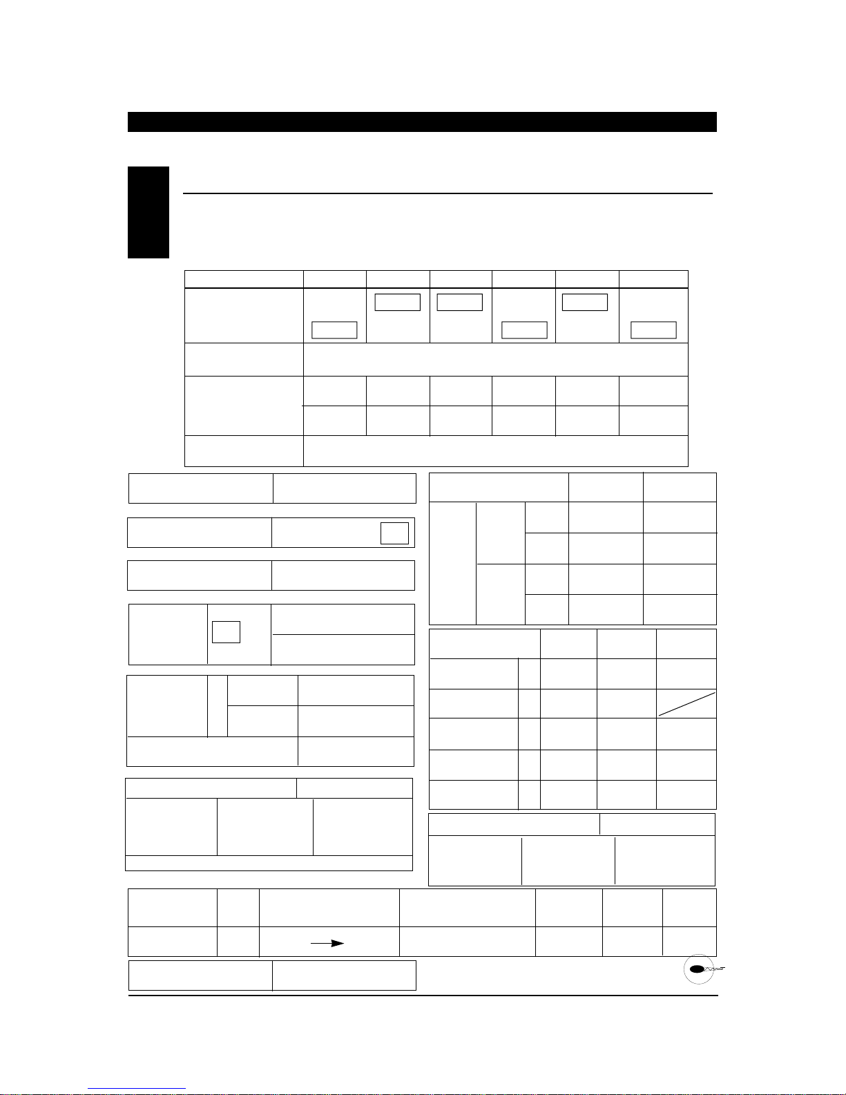
90
XP652 MANUAL Helicopter
CHAPTER 8:DAT A SHEETS
•
XP652 Helicopter
EA • A • E • CF
ERGO .46 (INITIAL SETUP WITH 3D PITCH/THROTTLE CURVES)8.2
D/R % %
EXP % %
D/R % %
EXP % %
TRIM OFFSET
CHANNEL THR (1) AIL (2) ELE (3) RUD (4) GER (5) PITCH (6)
NORM NORM NORM NORM NORM NORM
••••• •
REV REV REV REV REV REV
SUB-TRIM Adjust so that no trim is required
TRAVEL ADJUST + % + % + % + % + %
(TRV ADJ.) - % - % - % - % - %
FAIL-SAFE (S-PCM) Adjust only if S-PCM modulation is selected
80 80 100 100 150
80 80 100 100 150
90 90
20 20
100 100
20 20
0 50 100
100 50
Adjust for
full power
Adjust only if Z-PCM
modulation is selected
Store trim positions after
initial test flight
Factory Pre-Sets
Adjust for idle
30
30
Adjust for
engine off
REVERSE SW
*
* Note: Before flying, confirm that all controls
function in their proper direction.
** Note: Flight mode “S” (Stunt) shown is for 3D type flying
only and is not recommended for use by entry level pilots.
**
FAIL-SAFE TIME (Z-PCM)
AILE (AI) ELEV (EL)
POS O
POS 1
L 2 H
N
S
N
S
H
THRO CURVE
TLN, T2N, THN,
TLS, T2S
PITCH CURVE
PLN, P2N, PHN,
PLS, P2S, PHS,
PLH, P2H, PHH
% % %
% %
-2° pitch 5° pitch 10°pitch
-10°
pitch
0° pitch 10° pitch
-5° pitch 5° pitch 13°pitch
DUAL
RATE
•
EXP
D/R SW
GEAR SW
REVO-MIX
(RV)
HOLD RUDD OFFSET
(OFFSET HLD)
UP (U)
%
%
±
DOWN (D)
+
–
THRO HOLD
(HLD)
ON OF
PROG. MIX
A
CHANNEL
MASTER SLAVE MIX SWITCH OFFSET +GAIN -GAIN
ON • F1 • FO • H
POSITION
±
Modulation S-PCM • Z-PCM • PPM (FM)
Model Number 2
Model Name E46
**
AIL (2) ELE (3) Pitch (6)
CCPM MIXING ON • OFF
+
–
%%%
+
–
+
–
AIL (2) ELE (3) RUD (4)
STUNT TRIM ON • OFF
+
–
+
–
+
–
Adjust Stunt Trim values as needed.
Page 91

CHAPTER 8:DAT A SHEETS • XP652 Helicopter
ERGO .60 SPORT (INITIAL SET UP)8.3
91
XP652 MANUAL Helicopter
D/R % %
EXP % %
D/R % %
EXP % %
TRIM OFFSET
CHANNEL THR (1) AIL (2) ELE (3) RUD (4) GER (5) PITCH (6)
NORM NORM NORM NORM NORM NORM
••••• •
REV REV REV REV REV REV
SUB-TRIM Adjust so that no trim is required
TRAVEL ADJUST + % + % + % + % + %
(TRV ADJ.) - % - % - % - % - %
FAIL-SAFE (S-PCM) Adjust only if S-PCM modulation is selected
100 100 150 100 100
100 100 150 100 100
90 90
25 25
0 100
30 30
0 50 100
40 50
Adjust for
full power
Adjust only if Z-PCM
modulation is selected
Store trim positions after
initial test flight
Factory Pre-Sets
Factory Pre-Sets
Adjust for idle
40
20
Adjust for
engine off
REVERSE SW
*
* Note: Before flying, confirm that all controls
function in their proper direction.
FAIL-SAFE TIME (ZPCM)
AILE (AI) ELEV (EL)
POS O
POS 1
L 2 H
N
S
N
S
H
THRO CURVE
TLN, T2N, THN,
TLS, T2S
PITCH CURVE
PLN, P2N, PHN,
PLS, P2S, PHS,
PLH, P2H, PHH
% % %
% %
-2° pitch 5° pitch 10°pitch
-5° pitch 5° pitch 9° pitch
-5° pitch 5° pitch 13°pitch
DUAL
RATE
•
EXP
D/R SW
GEAR SW
REVO-MIX
(RV)
HOLD RUDD OFFSET
(OFFSET HLD)
UP (U)
%
%
±
DOWN (D)
+
–
THRO HOLD
(HLD)
ON OF
PROG. MIX
A
CHANNEL
MASTER SLAVE MIX SWITCH OFFSET +GAIN -GAIN
ON • F1 • FO • H
POSITION
±
Modulation S-PCM • Z-PCM • PPM (FM)
Model Number 3
Model Name E60
AIL (2) ELE (3) Pitch (6)
CCPM MIXING ON • OFF
+
–
%%%
+
–
+
–
AIL (2) ELE (3) RUD (4)
STUNT TRIM ON • OFF
+
–
+
–
+
–
Adjust Stunt Trim values as needed.
Page 92
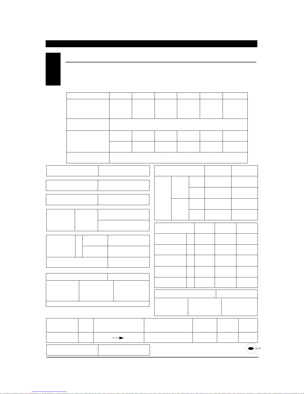
92
XP652 MANUAL Helicopter
CHAPTER 8:DAT A SHEETS
•
XP652 Helicopter
EA • A • E • CF
F • H • A • E
DA T A SHEETS8.4
D/R % %
EXP % %
D/R % %
EXP % %
TRIM OFFSET
CHANNEL THR (1) AIL (2) ELE (3) RUD (4) GER (5) PITCH (6)
NORM NORM NORM NORM NORM NORM
••••• •
REV REV REV REV REV REV
SUB-TRIM
TRAVEL ADJUST + % + % + % + % + % + %
(TRV ADJ.) - % - % - % - % - % - %
FAIL-SAFE (S-PCM)
REVERSE SW
*
FAIL-SAFE TIME (Z-PCM)
AILE (AI) ELEV (EL)
POS O
POS 1
L 2 H
N
S
N
S
H
THRO CURVE
TLN, T2N, THN,
TLS, T2S
PITCH CURVE
PLN, P2N, PHN,
PLS, P2S, PHS,
PLH, P2H, PHH
% % %
% % %
DUAL
RATE
•
EXP
D/R SW
GEAR SW
REVO-MIX
(RV)
HOLD RUDD OFFSET
(OFFSET HLD)
UP (U)
%
%
±
DOWN (D)
+
–
THRO HOLD
(HLD)
ON OF
PROG. MIX
A
CHANNEL
MASTER SLAVE MIX SWITCH OFFSET +GAIN -GAIN
ON • F1 • FO • H
POSITION
±
Modulation S-PCM • Z-PCM • PPM (FM)
Model Number ______________________
Model Name ________________________
AIL (2) ELE (3) Pitch (6)
CCPM MIXING ON • OFF
+
–
%%%
+
–
+
–
AIL (2) ELE (3) RUD (4)
STUNT TRIM ON • OFF
+
–
+
–
+
–
Adjust Stunt Trim values as needed.
Page 93

93
XP652 MANUAL Important Information
IMPORT ANT INFORMATION
Radio controlled models are a great source of
pleasure. Unfortunately, they can also pose a
potential hazard if not maintained and operated
properly. It is imperative that you install your radio
control system correctly. Additionally, your level of
piloting competency must be high enough to ensure
that you are able to control your aircraft under all
conditions. If you are a newcomer to radio controlled
flying, please seek help from an experienced pilot or
your local hobby shop.
Listed below are some safety Dos and Don’ts that must
be followed by all pilots:
• Ensure that your batteries have been properly
charged prior to initial flight.
• Keep track of the time that the system is turned on
so that you will have an idea of how long you can
safely operate your system.
• Perform a ground range check prior to the initial
flight of the day. See the “Daily Flight Checks
Section” below for information on how to do so.
• Check all control surfaces prior to each takeoff.
• Use frequency flags.
• Do not fly your model near spectators, parking
areas, or at any other area that could result in
injury to people or damage of property.
• Do not fly during adverse weather conditions. Poor
visibility can cause disorientation and loss of
control of your aircraft. Strong winds can cause
similar problems.
• Do not fly unless your frequency is clear.
Warning: Only one transmitter at a time can
operate on a given frequency. If you turn on your
transmitter while someone else is operating a
model on your frequency, both pilots will lose
control of their models. Only one person can use a
given frequency at a time. It does not matter if it is
AM, FM or PCM — only one frequency at a time.
• Do not point the transmitter antenna directly
toward the model. The radiation pattern from the
tip of the antenna is inherently low.
• Do not take chances. If at any time during flight you
observe any erratic or abnormal operation, land
immediately and do not resume flight until the
cause of the problem has been ascertained and
corrected.
1. Check the battery voltage on both the transmitter
and the receiver battery packs. Do not fly below
9.0 volts on the transmitter or below 4.7 volts on
the receiver. To do so can cause a crash of your
aircraft.
Note: When you check these batteries, ensure that
you have the polarities correct on your expanded
scale voltmeter.
2. Check all hardware (linkages, screws, nuts, bolts)
prior to each day’s flight. Be sure that binding
does not occur and that everything is properly
secured.
3. Ensure that all surfaces are moving in the proper
manner.
4. Perform a ground range check before each day’s
flying session. The range check should be as
follows:
• Do not extend the transmitter antenna at this
time. Turn the transmitter “on.”
• Turn the model “on.”
• Slowly walk away from the model while moving
the control surfaces. The aircraft should function
properly at a distance of 75–100 feet.
5. Just prior to starting your aircraft, turn “off” your
transmitter and then turn it back “on.” Do this
each time you start your aircraft. If any critical
switches are on without your knowledge, the
transmitter alarm will warn you at this time.
6. Ensure that all trim levers are in the proper
location.
7. Check to be sure that all servo pigtails and switch
harness plugs are secured in the receiver. Also,
make sure that the switch harness moves
completely in both directions.
GENERAL NOTES
1
DAILY FLIGHT CHECKS
2
Page 94

14. WARRANTY AND SERVICE INFORMA TION
WARRANTY COVERAGE
REPAIR SERVICE INSTRUCTIONS
Your new equipment is warranted to the original
purchaser against manufacturer defects in material
and workmanship for one year from the date of
purchase. During this period, Horizon Service Center
will repair or replace, at our discretion, any
component that is found to be factory defective at no
cost to the purchaser. This warranty is limited to the
original purchaser of the unit and is not transferable.
This warranty does not apply to any unit which has
been improperly installed, mishandled, abused, or
damaged in a crash, or to any unit which has been
repaired or altered by any unauthorized agencies.
Under no circumstances will the buyer be entitled to
consequential or incidental damages. This limited
warranty gives you specific legal rights; you also have
other rights which may vary from state to state. As
with all fine electronic equipment, do not subject
your unit to extreme temperatures, humidity or
moisture. Do not leave it in direct sunlight for long
periods of time.
In the event that your equipment needs service,
please follow the instructions listed below:
1. Check all on/off switches to be sure they are off.
This will speed the repair process of checking
battery condition.
2. Return your system components only
(transmitter, receiver, servos, etc.). Do not return
your system installed in a model car, boat,
plane, etc.
3. Use the original carton/packaging (molded foam
container), or equivalent, to ship your unit. Do
not use the carton itself as a shipping carton;
you should package the equipment carton within
a sturdy shipping container using additional
packing material to safeguard against damage
during transit. Include complete name and
address information inside the carton, as well
as clearly writing it on the outer label/return
address area. Ship your equipment fully
insured and prepaid. Horizon Service Center is
not responsible for any damages incurred during
shipping.
4. Include detailed information explaining your
operation of the equipment and problem(s)
encountered. Provide an itemized list of
equipment enclosed and identify any particular
area/function which may better assist our
technicians in addressing your concerns. Date
your correspondence and include your name,
mailing address, and a phone number where
you can be reached during the business day.
5. Warranty Repairs. To receive warranty service
you must include a legible photocopy of your
original dated sales receipt to verify your proofof-purchase date. Providing that warranty
conditions have been met, your radio will be
repaired without charge.
6. Normal Non-Warranty Repairs. Should your
repair cost exceed 50% of the retail purchase
cost, you will be provided with an estimate
advising you of your options.
Within your letter, advise us of the payment method
you prefer to use. Horizon Service Center accepts
VISA or MasterCard, please include your card number
and expiration date.
Mail your system to:
Horizon Service Center
4105 Fieldstone Road
Champaign, Illinois 61822
(217) 355-9511
www.horizonhobby.com
3
4
94
XP652 MANUAL Important Information
Page 95

72 MHz requires no special license to operate.
50/53 MHz requires the operator to have an FCC
amateur radio license (Ham).
CH.NO. FREQUENCY
15 72.090
16 72.110
17 72.130
18 72.150
19 72.170
20 72.190
21 72.210
22 72.230
23 72.250
24 72.270
25 72.290
26 72.310
27 72.330
28 72.350
29 72.370
30 72.390
31 72.410
32 72.430
33 72.450
34 72.470
35 72.490
CH.NO. FREQUENCY
36 72.510
37 72.530
38 72.550
39 72.570
40 72.590
41 72.610
42 72.630
43 72.650
44 72.670
45 72.690
46 72.710
47 72.730
48 72.750
49 72.770
50 72.790
51 72.810
52 72.830
53 72.850
54 72.870
55 72.890
56 72.910
57 72.930
58 72.950
59 72.970
60 72.990
CH.NO. FREQUENCY
00 50.800
01 50.820
02 50.840
03 50.860
04 50.880
05 50.900
06 50.920
07 50.940
08 50.960
09 50.980
72 MHz 50MHz
CH. NO. FREQUENCY FLAG COLOR
A1 53.100 Black/Brown
A2 53.200 Black/Red
A3 53.300 Black/Orange
A4 53.400 Black/Yellow
A5 53.500 Black/Green
A6 53.600 Black/Blue
A7 53.700 Black/Purple
A8 53.800 Black/Gray
53 MHZ
FREQUENCY CHART
5
72 MHz
FREQUENCY CHART
95
XP652 MANUAL Helicopter
*Channels 11–14 are not available
Page 96

DISTRIBUTED EXCLUSIVELY BY HORIZON HOBBY DISTRIBUTORS CHAMPAIGN, IL 61822
www.horizonhobby.com
®
 Loading...