

Page 1

ASSEMBLY INSTRUCTIONS
CCPM/SHAFT DRIVE
www.vigorpilot.com
Designed by Curtis Youngblood in
conjunction with JR Engineers
VIGOR CS SPECIFICATIONS
Overall Length 56.25"
Overall Height 18"
Main Rotor Blade Length 680 – 720 mm
(Main rotor blades not included)
Tail Rotor Diameter 10.34"
Gear Ratio 9.33:1:4.83
Gross W eight 10.2–10.5 lb
JRP9051.46
Revised 7/2001
™
®
Page 2

2
INTRODUCTION
The Wait is Over!
Congratulations on your purchase of the new JR
®
Vigor CS helicopter kit. The
Vigor CS, designed by 2-time World Champion and 12-time U.S. Nationals
Champion Curtis Youngblood, in conjunction with JR engineers, has been in
development for nearly 4 years and thousands of test flights, to bring you a model
that sets the new standard for others to be judged.
Designed By a Champion To Be a Champion
The Vigor CS was designed by Curtis with rigidity, durability, and simplicity in
mind. The Vigor CS’s unique main frame design utilizes two straight carbon fiber
frame plates and achieves its unmatched strength and rigidity through the use of
internal “I” beam supports, rather than the engine. This results in a very simple,
yet highly rigid frame that eliminates any unwanted loads from being applied to
the engine during flight.
In addition to the Vigor CS’s unique frame, the cooling system has also been
designed from the ground up by Curtis through countless hours of engine cooling
fan efficiency testing. The end result is a cooling system that provides double the
airflow of a conventional cooling system, with no increase in power consumption.
This system will allow the engine to run more consistently, and at a more
consistent temperature.
Low Parts Count Means Quick Assembly
You will find that your Vigor CS will assemble very quickly due to its wellthought-out/straight-forward design, low parts count, and preassembled main
rotor head, washout unit, and tail pitch slider assemblies. The building time for
the Vigor CS usually takes only 10–12 hours from start to finish.
CCPM Control System
Curtis and the JR engineers have taken the CCPM one step further. The Vigor CS
can be set up with the normal 120-degree CCPM system that is supported in most
of today's modern computer helicopter radio systems. Curtis has devised a new
CCPM configuration. CCPM 140 places the ball links on the swashplate 140º
back from the forward ball, then the rear balls are extended, placing them the
same for to aft distance from the center of the mainshaft as the front ball. The
main advantage is that all three servos going to the swashplate now have the same
throw. With conventional 120 CCPM, the throws to the forward servos must be
reduced with radio programming by 50%. This causes the longer-throwing servos
to lag behind the shorter-throwing servo during quick cyclic inputs.
Team Tips
Throughout the sections of this instruction manual, you will find dozens of
“Team Tips.” These tips have been provided by Team JR’s Curtis Youngblood
and Len Sabato to guide you through the assembly of your Vigor CS with helpful
tips and suggestions that will help you get the most from your new JR Vigor CS
from the first flight.
www.vigorpilot.com
For the latest, up-to-date information on the Vigor CS, visit the Vigor Web page
at www.vigorpilot.com. vigorpilot.com will contain up-to-date information on
new upgrade parts and radio programming tips, as well as many helpful tips and
suggestions from Team JR’s pilots to keep you on the cutting edge of Vigor CS
developments and fine tuning.
WARNING
The radio controlled model helicopter contained in this kit is not a toy but a
sophisticated piece of equipment. This product is not recommended for use by
children. Radio controlled models such as this are capable of causing both
property damage and/or bodily harm to both the operator/assembler and/or
spectator if not properly assembled and operated. Horizon Hobby, Inc. assumes
no liability for damage that could occur from the assembly and/or use/misuse of
this product.
AMA INFORMATION
We strongly encourage all prospective and current R/C aircraft pilots to join the
Academy of Model Aeronautics. The AMAis a non-profit organization that
provides services to model aircraft pilots. As an AMA member, you will receive a
monthly magazine entitled Model Aviation, as well as a liability insurance plan to
cover against possible accident or injury. All AMA charter aircraft clubs require
individuals to hold a current AMAsporting license prior to operation of their
models. For further information, you can contact the AMAat
Academy of Model Aeronautics
5151 East Memorial Drive
Muncie, IN 47302
(317) 287-1256
PREASSEMBLY INFORMATION
When first opening your Vigor CS kit, you will notice that all of the parts are
packaged and numbered to coordinate with the assembly step numbers of this
instruction manual.
All small hardware (nuts, bolts, washers, etc.) for each step are separated and
packaged separately within the main parts bags. When beginning a section, you
will need to open only the bag with the corresponding number to the section you
are going to start. It is suggested that you place all of the hardware in an open
container (e.g., coffee can) during assembly so as not to lose any of the small
parts. It may also be helpful to familiarize yourself with the various sizes of
screws, bolts, nuts, etc., as illustrated in the appropriate assembly section before
you begin assembly. At the end of each assembly, in most cases, there should be
no parts remaining.
NOTE: Your kit also includes JR red and green threadlock. Unlike conventional
U.S.-made threadlock, JR red is actually the U.S. equivalent of blue. JR green is
actually the equivalent of U.S. red.
Great care has been taken in filling the bags with the correct quantity of parts and
hardware for each section. However, occasionally mistakes do happen. In the
event that you find a parts shortage or are in need of technical assistance, please
contact your local JR Heli Division parts dealer or contact the Horizon Service
Center directly.
Horizon Service Center
4105 Fieldstone Road
Champaign, IL 61822
(217) 355-9511 (9 a.m. to 5 p.m. CST)
™
Page 3

3
INDEX
Section Description Page
Section Description Page
Introduction . . . . . . . . . . . . . . . . . . . . . . . . . . . . . . . . . . . . . . . . . . . . . .2
Vigor CS Features . . . . . . . . . . . . . . . . . . . . . . . . . . . . . . . . . . . . . . . . 4
Radio System Requirements (not Included) . . . . . . . . . . . . . . . . . . . . 4
Engine Requirements (not Included) . . . . . . . . . . . . . . . . . . . . . . . . . . 5
Building Supplies (not Included) . . . . . . . . . . . . . . . . . . . . . . . . . . . . . 5
Tools Needed to Assemble the JR Vigor CS (not Included) . . . . . . . . .6
Field Equipment Required (not Included) . . . . . . . . . . . . . . . . . . . . . . 6
Hardware Identification . . . . . . . . . . . . . . . . . . . . . . . . . . . . . . . . . . . . 7
1-1 Clutch Bell/Start Shaft Assembly . . . . . . . . . . . . . . . . . . . 8
1-2 Elevator Arm Assembly . . . . . . . . . . . . . . . . . . . . . . . . . . . 9
1-3 T-Arm Lever Assembly . . . . . . . . . . . . . . . . . . . . . . . . . .10
1-4 Fuel Tank Assembly . . . . . . . . . . . . . . . . . . . . . . . . . . . . 10
2-1A Main Frame Assembly: Bearing Block/Clutch Installation .11
2-1B Elevator Arm Installation . . . . . . . . . . . . . . . . . . . . . . . . .12
2-2 Main Frame Assembly: Crossmember Installation . . . . . 13
2-3A T-Lever Installation . . . . . . . . . . . . . . . . . . . . . . . . . . . . . .14
2-3B Elevator Control Arm Installation . . . . . . . . . . . . . . . . . .15
2-4 Main Frame Assembly: Engine Mount/Cross Member
Installation . . . . . . . . . . . . . . . . . . . . . . . . . . . . . . . . . . . . 16
2-5 Main Frame Assembly: Bottom Plate Installation . . . . . . 17
2-6 Fuel Tank Installation . . . . . . . . . . . . . . . . . . . . . . . . . . . 18
2-7 Front Radio Bed Installation . . . . . . . . . . . . . . . . . . . . . . 19
3-1A Main Drive Gear/Autorotation Assembly . . . . . . . . . . . . 19
3-1B Bevel Gear Assembly . . . . . . . . . . . . . . . . . . . . . . . . . . . .20
3-2 Main Shaft/Main Drive Gear Installation . . . . . . . . . . . . 20
3-3 Landing Gear Assembly Installation . . . . . . . . . . . . . . . . 21
3-4 Cooling Fan/Hub Installation . . . . . . . . . . . . . . . . . . . . . 21
3-5 Clutch Assembly Attachment . . . . . . . . . . . . . . . . . . . . . 22
3-6 Engine Installation . . . . . . . . . . . . . . . . . . . . . . . . . . . . . . 22
3-7 Cooling Fan Shroud Bracket Attachment . . . . . . . . . . . . 23
3-8 Bolt Tightening Order/Gear Mesh Adjustment . . . . . . . . 23
3-9 Cooling Fan Shroud Installation . . . . . . . . . . . . . . . . . . . 24
3-10 Installation of the Muffler/Fuel Line Connections . . . . . 24
4-1 Swashplate Assembly . . . . . . . . . . . . . . . . . . . . . . . . . . . 25
4-2 Swashplate/Washout Assembly Installation . . . . . . . . . . 26
4-3 Rotor Head Installation . . . . . . . . . . . . . . . . . . . . . . . . . . 27
4-4 Flybar Installation . . . . . . . . . . . . . . . . . . . . . . . . . . . . . . 28
4-5 Flybar Paddle Attachment . . . . . . . . . . . . . . . . . . . . . . . . 28
4-6 Swashplate/T-Arm Control Rod Installation . . . . . . . . . . 29
5-1 Tail Drive Shaft Preparation . . . . . . . . . . . . . . . . . . . . . . .30
5-2 Tail Drive Shaft Assembly . . . . . . . . . . . . . . . . . . . . . . . . 31
5-3 Bevel Pinion Gear Assembly . . . . . . . . . . . . . . . . . . . . . . 31
5-4 Boom/Bevel Pinion Gear Installation/Adjustment . . . . . 32
5-5 Tail Support Clamp Installation . . . . . . . . . . . . . . . . . . . . 33
5-6 Tail Boom Brace Assembly . . . . . . . . . . . . . . . . . . . . . . . 33
5-7 Tail Brace Installation . . . . . . . . . . . . . . . . . . . . . . . . . . . 34
5-8 Horizontal/Vertical Fin Installation . . . . . . . . . . . . . . . . . 34
5-9 Tail Center Hub Assembly . . . . . . . . . . . . . . . . . . . . . . . . 35
5-10 Tail Blade Holder Assembly . . . . . . . . . . . . . . . . . . . . . . .35
5-11 Steel Joint Ball Installation . . . . . . . . . . . . . . . . . . . . . . . .36
5-12 Tail Drive Shaft/Tail Gear Box Installation . . . . . . . . . . .36
6-1 Upper Servo Tray/Body Mount Attachment . . . . . . . . . . 37
6-2 Servo/Switch Harness Installation . . . . . . . . . . . . . . . . . . 38
6-3 Tail Control Rod Assembly . . . . . . . . . . . . . . . . . . . . . . . 39
6-4 Tail Control Rod/Tail Guide Attachment . . . . . . . . . . . . . 39
6-5 Gyro/Receiver/Battery Installation . . . . . . . . . . . . . . . . . 40
Radio System Preparation . . . . . . . . . . . . . . . . . . . . . . . . . . . . . . . . . 41
Understanding CCPM Control Systems . . . . . . . . . . . . . . . . . . . .42-43
Important CCPM Programming Do’s & Dont’s . . . . . . . . . . . . . .44-45
CCPM Software Activation . . . . . . . . . . . . . . . . . . . . . . . . . . . . . .46-49
7-1 Preparation and Installation of Servo Horns . . . . . . . . . . 50
7-2 CCPM Servo Centering with the Sub-Trim Function . . .51
7-3 Control Rod Assembly . . . . . . . . . . . . . . . . . . . . . . . . . . . 52
7-4 CCPM Control Rod Attachment . . . . . . . . . . . . . . . . . . . 53
7-5 Tail Control Rod Connection . . . . . . . . . . . . . . . . . . . . . . 54
7-6 Throttle Linkage Connection . . . . . . . . . . . . . . . . . . . . . . 55
7-6.1 Throttle Arm/Servo Horn Positions . . . . . . . . . . . . . . . . .56
7-7 Checking the Swashplate for Level . . . . . . . . . . . . . . . . .57
7-8 Pitch-to-Aileron Mixing Adjustment with Travel Adjust .58
7-9 Pitch-to-Elevator Mixing Adjustment with Travel Adjust 59
Final Servo Adjustment and Radio Setup . . . . . . . . . . . . . . . . . . .60-61
8-1 Trimming of Body Assembly . . . . . . . . . . . . . . . . . . . . . 62
8-2 Grommet Attachment . . . . . . . . . . . . . . . . . . . . . . . . . . . 62
8-3 Body Attachment & Final Fitting . . . . . . . . . . . . . . . . . . 63
Decal Placement . . . . . . . . . . . . . . . . . . . . . . . . . . . . . . . . . . . . . . 64-65
8-4 Main Rotor Blade Attachment (Blades not included) . . . 66
Preflight Check . . . . . . . . . . . . . . . . . . . . . . . . . . . . . . . . . . . . . . . . . .67
General Maintenance . . . . . . . . . . . . . . . . . . . . . . . . . . . . . . . . . . . . .68
P-1 Assembly Process – Main Rotor Head 1 . . . . . . . . . . . . . 69
P-2 Assembly Process – Main Rotor Head 2 . . . . . . . . . . . . . 69
P-3 Assembly Process – Main Rotor Head 3 . . . . . . . . . . . . . 70
P-4 Assembly Process – Main Rotor Head 4 . . . . . . . . . . . . . 70
P-5 Assembly Process – Main Rotor Head 5 . . . . . . . . . . . . . 71
P-6 Assembly Process – Washout Unit . . . . . . . . . . . . . . . . . 71
P-7 Assembly Process – Tail Slide Ring . . . . . . . . . . . . . . . . .72
P-8 Assembly Process – Flybar Control Arm . . . . . . . . . . . . 72
Data Sheets . . . . . . . . . . . . . . . . . . . . . . . . . . . . . . . . . . . . . . . . . . 73-77
Start Shaft/Clutch/Engine Assembly Parts List . . . . . . . . . . . . . . 78-79
Main Frame/Landing Gear/Autorotation Assembly Parts List . . . 80-81
Swashplate/CCPM Control System Parts List . . . . . . . . . . . . . . .82-83
Main Rotor Head/Washout Assembly Parts List . . . . . . . . . . . . . .83-84
Tail Drive System/Shaft Drive Parts List . . . . . . . . . . . . . . . . . . .86-87
Tail Rotor Blade Holder/Tail Brace . . . . . . . . . . . . . . . . . . . . . . . .88-89
Body Set/Fuel Tank Assembly Parts List . . . . . . . . . . . . . . . . . . .90-91
Page 4
4
VIGOR™CS FEATURES
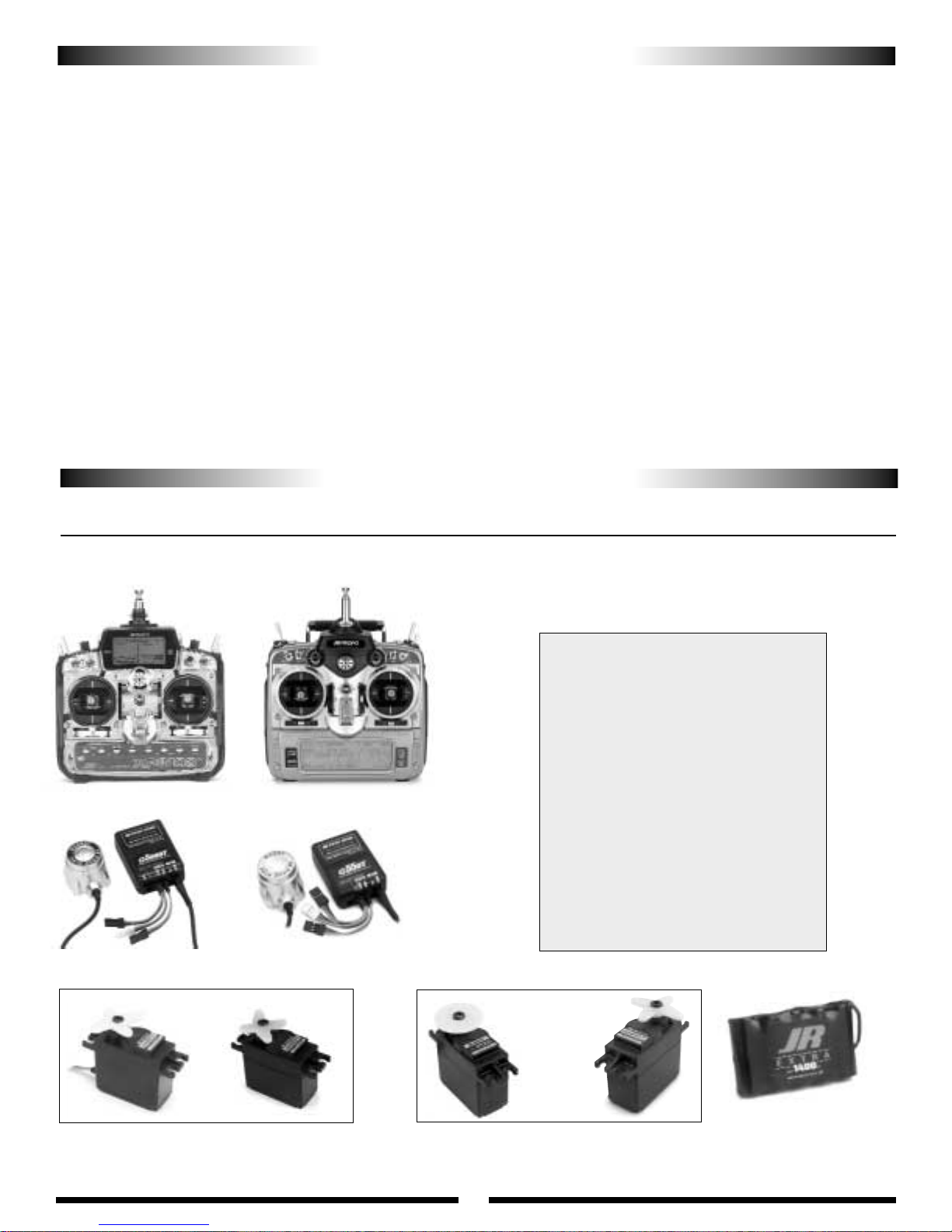
ITEMS REQUIRED TO COMPLETE THE JR VIGOR CS
Frame:
• Unique cabon fiber frame design derives structural integrity without the engine
• Stiffness of frame is double to triple conventional designs — reduces vibration
for improved gyro, engine & powertrain performance
• Motor mount acts as a jig for easy, goof-proof powertrain alignment
• Straight frame design with full length I-beams can’t scissor like conventional
“stacked” frames
Tail Drive System:
• Goof-proof self-aligning torque tube tail drive system
• Ultra-durable aluminum drive shaft
• Preassembled tail gear box
• Dual point tail pitch slider & lever
• Special 3D carbon fin set
• Aluminum fin mounts
Control System:
• JR 120/140 push pull CCPM
• Dual bearing aluminum T levers
• CNC-machined aluminum elevator arm
• High-grade 120/140 CCPM swashplate
Rotor Head:
• Improved, ultra-true mounting clamp design
• Swashplate timing is pre-positioned at optimum setting
• Revised delta offset positioning offers improved forward flight stability and
reduced boom strike potential
• New lightweight 25 gram paddle design is perfect for 3D or fun flying
• Flybar weights included
Drive T rain/Cooling:
• Constant drive split main gear design for extreme 3D flying
• High-efficiency cooling system increases airflow to double the normal amount
• Main shaft bearing spacing is 50% wider than conventional designs for
superior rigidity
• Additional BB engine drive pinion gear support keeps power loads from being
introduced to the engine
• New larger 20-ounce fuel tank for extended flight times
• CNC-machined delrin bevel drive gear
• Optimum 9.33 to 1 to 4.83 gear ratio
JR XP8103
JR PCM10X
JRPB4340
1400mAh Battery Pack
JRPS8411 Ultra Torque Digital OR JRPS8231 Ultra Precision Digital
Aileron, Elevator, Collective, Throttle Servos Tail Rotor Servos
8700G High Speed Super OR 8417 High Speed Digital
CCPM-Ready JR Radio Systems
Most current JR heli radio systems (XP652,
XP8103 w/digital trims, 10X, as well as older 10
series systems) are equipped with 120° CCPM
electronics for use with JR CCPM machines.
Radios you may be flying now, like the X347,
X388S, XP783, and XP8103*, have 120° CCPM
capability built in but require activiation by the
Horizon Service Department. For details, please
call (217) 355-9511.
*Please note that many XP8103 systems have the CCPM
function already activated. Please check with the Horizon
Service Center for details.
Current Radio Systems
JRP1656**PCM 10X, 120° & 140° CCPM
JRP8622**XP8103FM, 120° CCPM
JRP8653**XP8103PCM, 120° CCPM
JRP6622**XP652 FM,120° CCPM
JR G5000T Gyro OR
JR G550T Gyro
1. RADIO SYSTEM REQUIREMENTS (NOT INCLUDED):
6-channel or greater R/C helicopter system with 120° or 140° CCPM with 5 servos
1400mAh receiver battery and gyro
Page 5

5
Double-Sided Servo
Mounting Tape
Nylon Wire Ties
(to secure radio wires)
Pacer Poly Zap 1/2 oz
(PAAPT22)
JB Weld Epoxy Adhesive
(JBW8265S)
Pacer Zip Kicker
(PAAPT15) Optional
Heavy-Duty Servo Wheels
(3 pcs) w/Screws
JRPA216 or equivalent
Light Oil
Rubbing Alcohol
Fuel Filter
Glow Plugs
( HAN3020 )
2. ENGINE REQUIREMENTS (not included):
3. BUILDING SUPPLIES (not included):
The following items are needed to complete the assembly of the JR Vigor CS:
A .60 – .61 R/C helicopter engine is required.
A special helicopter type muffler is also required.
OS 61 WC Heli Engine
YS STII Heli Engine
KSJ520 (O.S.)
KSJ583 (YS)
YEIMP900 Muscle Pipe Set: Right
High-Speed
Grease
Medium
Silicone Fuel
Tubing (3 ft)
Primer & Paint
(for canopy finishing)
Page 6
6
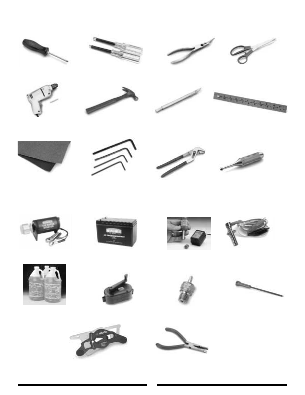
Needle-Nose Pliers
Drill and Drill Bits
Allen Wrenches: 1.5, 2.0, 2.5,
3.0 mm
Sandpaper (80–120 Grit)
Adjustable Pliers
Small Hammer
Hobby Knife
Metric Ruler
Scissors
12-Volt Electric Starter
12-Volt Starting Battery
Helicopter Fuel 15% –30%
Pitch Gauge
(JRP960326)
Fuel Pump
Ball Link Pliers
(RVO1005)
Glow Plugs
(HAN3020)
Hex Starting Shaft
(JRP960090)
Phillips Screwdriver
Nut Drivers: 5 mm, 7 mm
4. TOOLS NEEDED TO ASSEMBLE THE JR VIGOR CS (not included):
5. FIELD EQUIPMENT REQUIRED (not included):
JR Ball Link Sizing Tool
JRP60219
( Optional )
1.5-Volt Glow Plug Battery OR
Must have long shaft to reach glow plug.
Remote Glow Plug Adaptor
Page 7

7
Socket Head Bolt
Self T apping Screw
Flat W asher
.05mm
Flat Head Screw
Lock Nut
There are a variety of sizes and shapes of hardware included in this kit.
Prior to assembly, please be careful to identify each screw by matching it
to the full size screw outlines included in each step.
All of the hardware, screws, nuts, etc., contained in the Vigor
™
CS kit are
described in the following A, B, C manner:
C
C
C
A
A
B
A
A
B
B
B
C
A
B
3 x 8 mm Socket Head Bolt
Set Screw
C
A
B
C
C
A
A
A
A
B
2 x 8 mm Flat Head Screw
2.6 x 10 mm Self Tapping Screw
A
B
B
3 mm Flat Washer
A
B
B
3 mm Lock Nut
Star W asher
A
B
B
3 mm Star Washer
A
B
Flat Head Cap Screw
A
C
B
C
3 x 8 mm Flat Head Cap Screw
A
Hex Nut
A
B
B
2 mm Hex Nut
C
A
B
4 x 4 mm Set Screw
HARDWARE IDENTIFICATION
Page 8
8
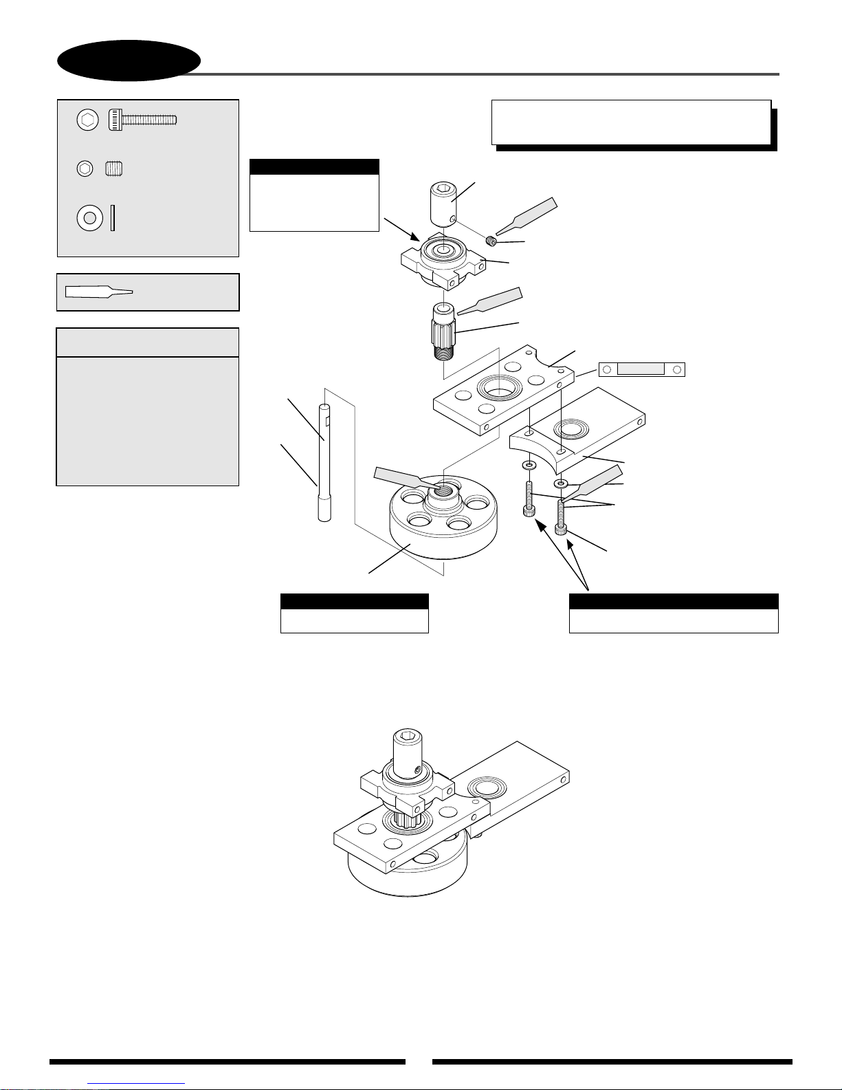
1-1
CLUTCH BELL/START SHAFT ASSEMBLY
...2 pcs
Socket Head Bolt, 3 x 14 mm
...................1 pc
Set Screw, 4 x 4 mm
....................2 pcs
Flat Washer, 3 mm
Use Red & Green
Threadlock
Assembly Order:
1. Attach pinion to clutch bell
2. Attach clutch bell to
bearing block “A”
3. Attach start shaft bearing
block to pinion
4. Assemble start shaft
assembly
5. Attach bearing block “B”
Note:
Be sure the bearing
with the 5 mm ID
faces upward.
Start Shaft
Lightly Oil
Green
TEAM TIP: Clean areas with rubbing alcohol to
remove any oil residue before applying threadlock.
Starter Hex
Adaptor
Red
Set Screw,
4 x 4 mm
Start Shaft
Bearing Block
Green
Pinion Gear
Long Bearing Block “A”
Position so that
bearing is at
the top of the
bearing block.
Long Bearing Block “B”
Flat Washer, 3 mm (2 pcs)
Red
Apply red threadlock
& tighten at Step 3-8
Socket Head Bolt,
3 x 14 mm (2 pcs)
Clutch Bell Assembly
Note:
Use Green Threadlock
Complete Assembly
Note:
Do not fully tighten at this time.
Page 9
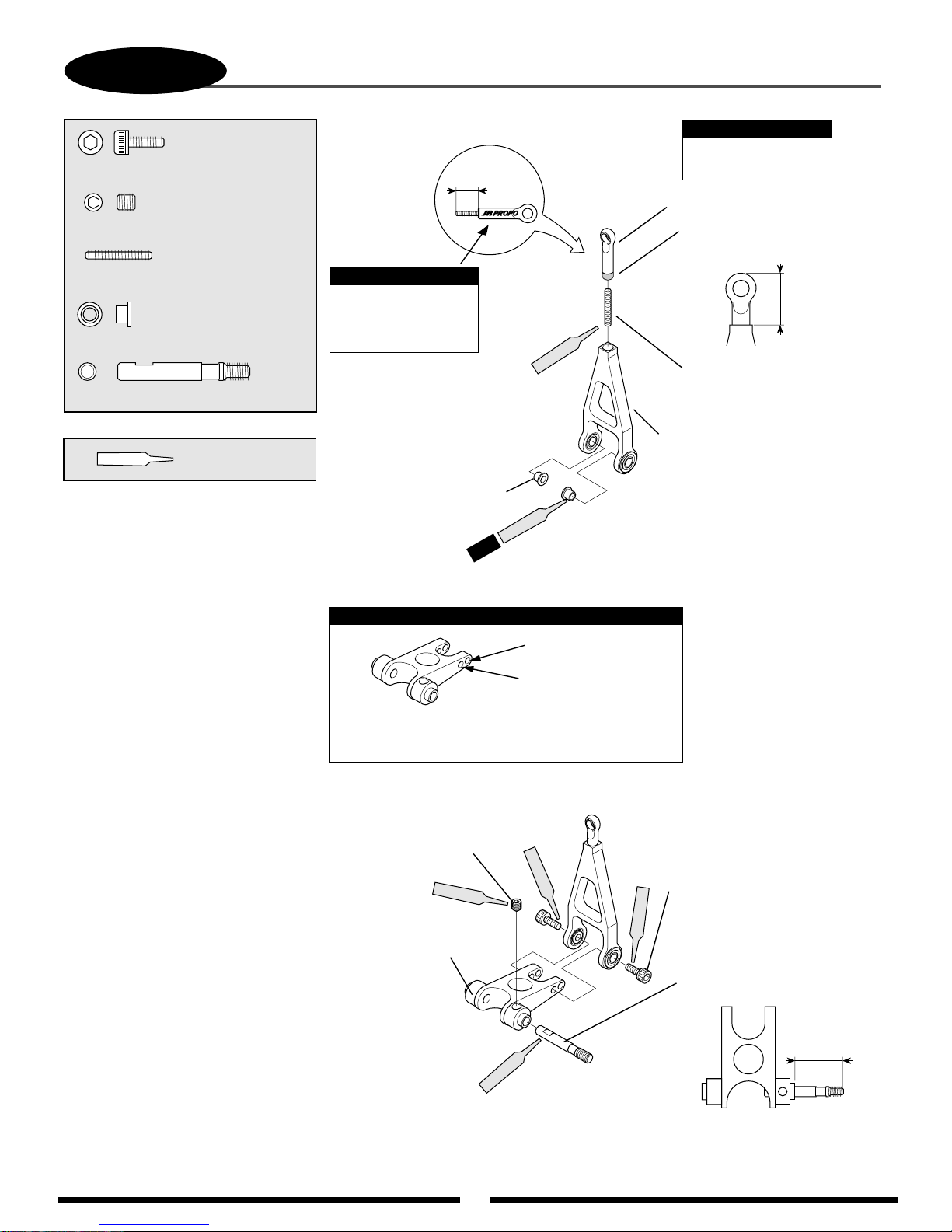
1-2
9
ELEVATOR A-ARM ASSEMBLY
..........................2 pcs
Socket Head Bolt, 3 x 8 mm
...............................1 pc
Set Screw, 4 x 4mm
............................1 pc
Threaded Rod, 2.3 x 15 mm
.............................2 pcs
A-Arm Bearing Collar
A-Arm Link Base Spindle
Use Red
Threadlock
.....1 pc
5 mm
Note:
Remove JR® Propo
from outside of link
using a hobby knife.
A-Arm
Bearing Collar (2 pcs)
2 pcs
Red
Note:
Oil outside of link
to ease assembly.
Special Universal Link (White)
Remove 1 mm from the bottom
of this link using a hobby knife
11 mm
Red
Threaded Rod, 2.3 x 15 mm
Elevator A-Arm
Apply a very thin coating of Threadlock
so that it will not seep into the bearing.
Note:
Wide Range
Standard Range*
*Connect the A-arm to the A-arm base
in the standard range position as shown.
Set Screw, 4 x 4 mm
Red
Red
A-Arm
Socket Head Bolt, 3 x 8 mm (2 pcs)
Red
A-Arm Base
18.5 mm
Red
Page 10
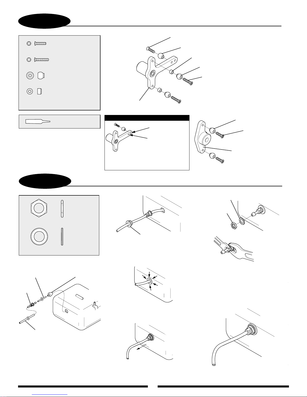
1-3
10
.......................... 4 pc
Flat Head Screw, 2 x 8 mm
.................... 4 pcs
Flat Head Screw, 2 x 10 mm
T-ARM LEVER ASSEMBLY
Flat Head Screw, 2 x 8 mm (2 pcs)
Steel Joint Ball
Joint Ball Spacer, 2.2 mm (4 pcs)
Steel Joint Ball (6 pcs)
.......................... 8 pcs
Steel Joint Ball
..............................4 pcs
Joint Ball Spacer, 2.2 mm
Use Red Threadlock
on all screws
1-4
Nut, 7 mm
FUEL TANK ASSEMBLY (BAG #6)
...........1 pc
T-Arm Assembly
Note:
Wide Range
Standard Range
*Connect the control ball to the
T-Arms in the standard range
position as shown.
Flat Head Screw, 2 x 10 mm (4 pcs)
Steel Joint Ball (2 pcs)
Flat Head Screw,
*
Washer, 7 x 12 x 1 mm
Nut, 7 mm
2 x 8 mm (2 pcs)
Elevator Control Arm
...........1 pc
Washer, 7 x 12 x 1 mm
Silicone Tube (small)
Use tubing included in
seperate package in kit.
Nipple
Medium Silicone Fuel
Tubing (not included) —
Connect to engine carburetor.
1. Cut the small silicone fuel
tubing(included) to a length of 77 mm.
Next, connect the fuel tank clunk,
nipple, and medium silicone fuel
tubing (not included) as shown above.
Fuel
Tank
Clunk
Fuel Tank Grommet
2. Insert the assembly into the fuel tank
opening so that the nipple is inside the
tank. Next, slide the fuel tank grommet
over the medium fuel tubing
3. Inset the fuel tank grommet into the
fuel tank opening, making sure that it
is fully seated.
4. Pull the medium fuel tubing out of the
fuel tank until the threads of the fuel tank
nipple are exposed.
.
Use two wrenches if necessary
to secure tank nipple.
5. Remove the medium silicone fuel
tubing from the nipple and secure
the nipple to the fuel tank using
the 7 x 12 x 1 mm washer and
7 mm nut supplied. Be sure to
secure this assembly firmly to
avoid leakage.
Complete Assembly
Page 11

11
2-1A
MAIN FRAME ASSEMBLY: BEARING BLOCK/CLUTCH INSTALLATION
.....................................4 pcs
Socket Head Bolt, 3 x 8 mm
Socket Head Bolt, 3 x 40 mm
..................5 pcs
Nylon Lock Nut, 3 mm
..................8 pcs
Flat Washer, 3 mm
*
*
...5 pcs
Note:
Prior to assembling the main
frames, sand all edges of the
frame using 120 grit sandpaper.
This will prevent wire chaffing
during continuous operation.
Nylon Lock Nut, 3 mm (5 pcs)
Top Bearing Case
Note:
Positon so that bearing faces upward.
Up
Top Bearing Case Direction
Flat Washer, 3 mm (12 pcs)
Socket Head
Bolt, 3 x 8 mm (12 pcs)
*TEAM TIP: Don’t tighten bolts completly at this
time. These bolts will be tightened in Step 3-8 to
achieve proper alignment.
*
*
*
*
*
*
*
Socket Head Bolt, 3 x 40 mm (5 pcs)
Flat Washer, 3 mm (5 pcs)
Main Frame (2 pcs)
Page 12
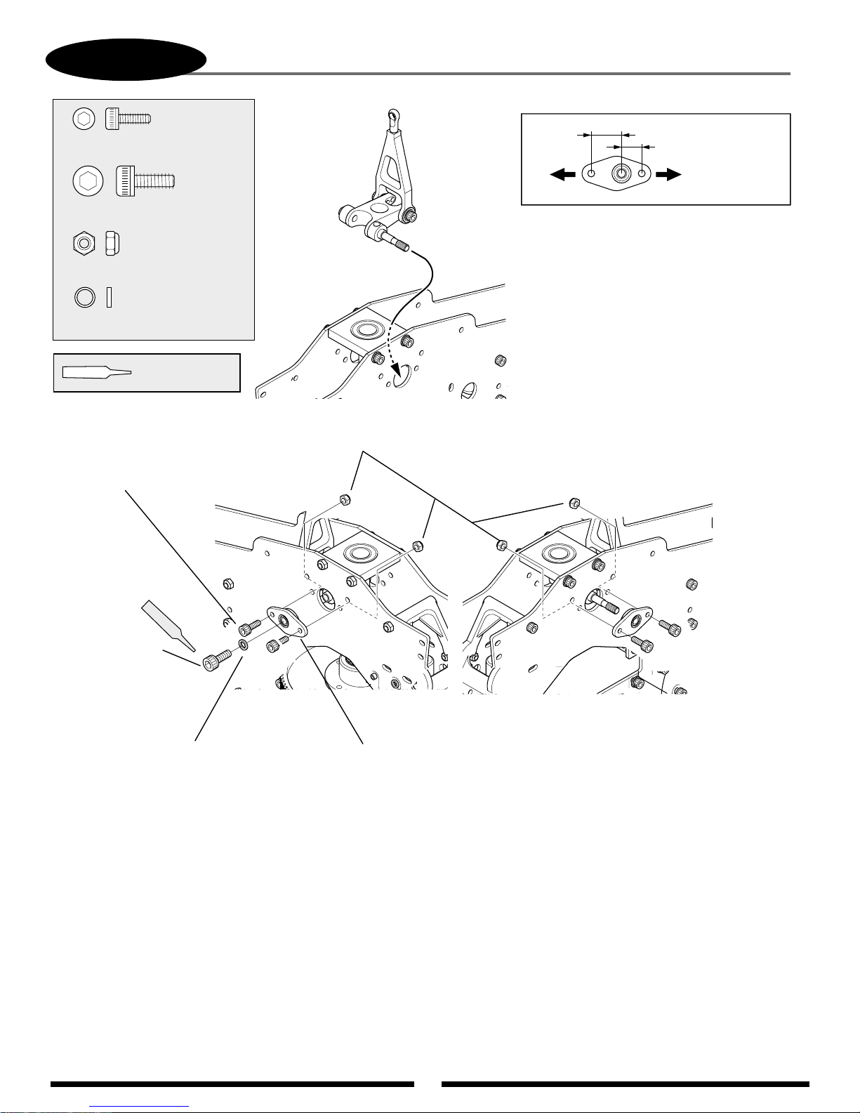
12
2-1B
...............4 pcs
Socket Head Bolt, 3 x 8 mm
Socket Head Bolt, 4 x 10 mm
.......................4 pcs
Nylon Lock Nut, 3 mm
........................ 1 pc
Spacer, 4 x 5 x 1 mm
Use Red
Threadlock
ELEVATOR ARM INSTALLATION
........1 pc
Nylon Lock Nut, 3 mm (4 pcs)
Direction of Installation
Long
Front
Standard Range
Short
Rear
Socket Head Bolt, 3 x 8 mm (4 pcs)
Red
Socket Head
Bolt 4 x 10 mm
Spacer, 4 x 5 x 1 mm
Elevator Arm Bearing Case (2 pcs)
Page 13

13
2-2
.....................2 pcs
Set Screw, 3 x 18 mm
MAIN FRAME ASSEMBLY: CROSSMEMBER INSTALLATION
Cross Member, 24 mm
Red
Set Screw,
3 x 18 mm (2 pcs)
.....1 pc
Cross Member, 32 mm
...................3 pcs
Nylon Lock Nut, 3 mm
............2 pcs
Cross Member, 24 mm
Socket Head Bolt, 3 x 40 mm....3 pcs
Use Red
Threadlock
*TEAM TIP: Do not apply
Threadlock to bolts unless
you will procede through
Step 3-8 during this
building session.
Cross Member, 32 mm
10 mm
Note:
When installing the cross member A,
be careful not to over tighten.
Set Screw, 3 x 18 mm (2 pcs)
Red
Nylon Lock
Nut, 3 mm (3 pcs)
Cross Member A
(note correct direction)
Red
Cross Member,
24 mm (2 pcs)
Socket Head Bolt, 3 x 40 mm (3 pcs)
*TEAM TIP: Don’t tighten bolts completely at this time.
These bolts will be tightened in Step 3-8.
Page 14
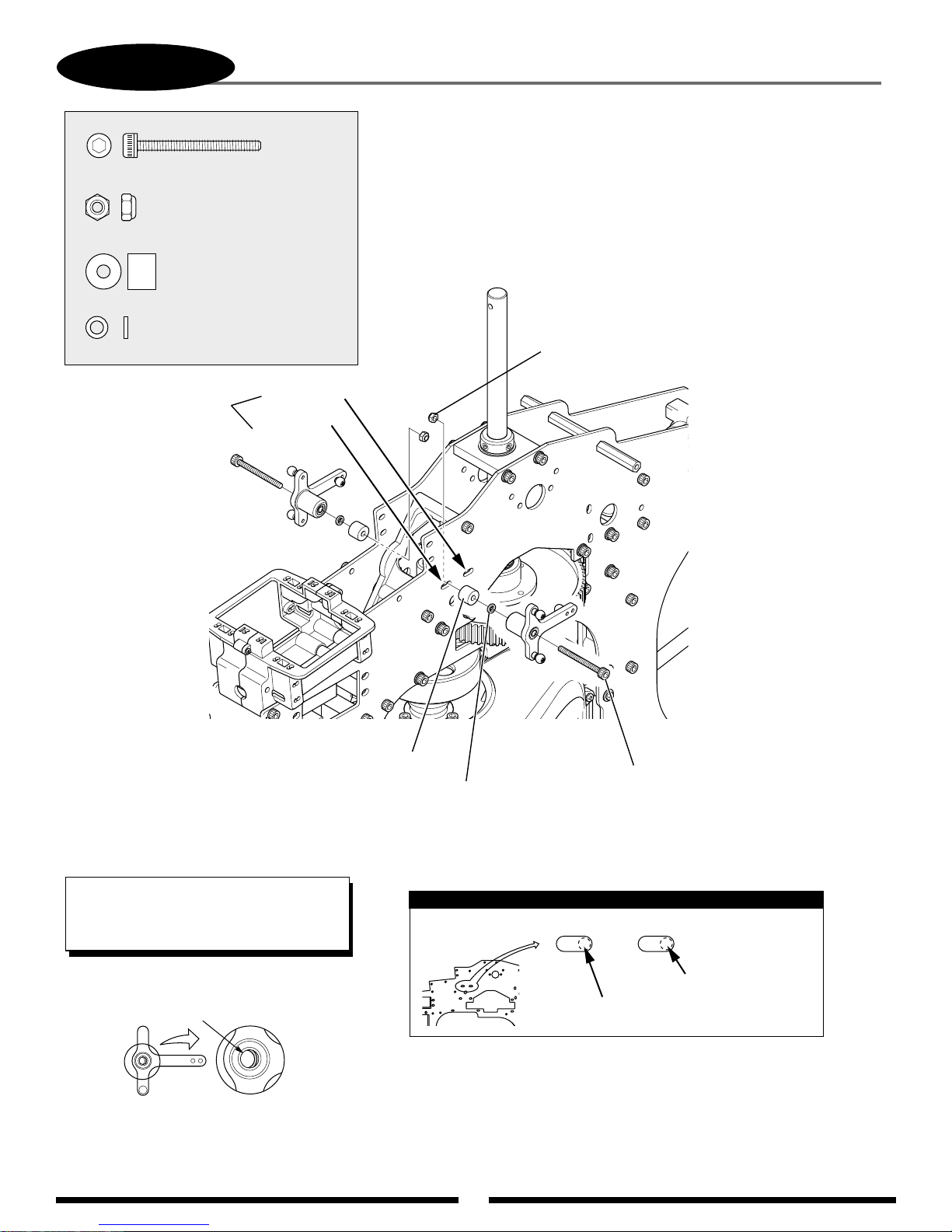
T-LEVER INSTALLATION
2-3A
Socket Head Bolt, 3 x 28 mm (2 pcs)
Nylon Lock Nut, 3 mm (2 pcs)
Mixing Lever Spacer (2 pcs)
Spacer, 3 x 5 x 1 mm (2 pcs)
140 CCPM
120 CCPM
Socket Head Bolt, 3 x 28 mm
Nylon Lock Nut, 3 mm
....2 pcs
......................................2 pcs
Mixing Lever Spacer
...............................2 pcs
..................................... 2 pcs
Spacer, 3 x 5 x 1 mm
T-Lever Positions
If a collar in T arm is too onesided, please correct the collar to
center before inserting the bolts.
140 CCPM/Standard Range
120 CCPM/Standard Range
T-Lever Position on Main Frame Slots
Note:
TEAM TIP: If you have difficulty reaching the
3 mm T-lever nuts, remove the two top bolts
from the plastic crossmember and slide the
crossmember forward.
14
Page 15
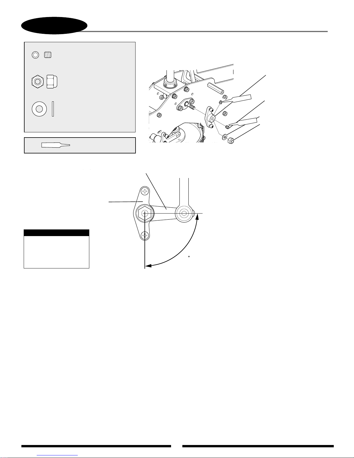
15
2-3B
ELEVATOR CONTROL ARM INSTALLATION
Elevator Control Arm
*Standard Range Direction
Nylon Lock Nut, 4 mm
Flat Washer, 4 mm
Set Screw, 4 x 4 mm
90
Nylon Lock Nut, 4 mm
..................................1 pc
Flat Washer, 4 mm
...................................1 pc
Set Screw, 4 x 4 mm
....................................2 pcs
Use Red
Threadlock
Elevator
Control Arm
A-Arm Base
Make sure that the
elevator control arm
is installed so that it is
90° to the A-arm base.
Note:
Red
Red
Page 16
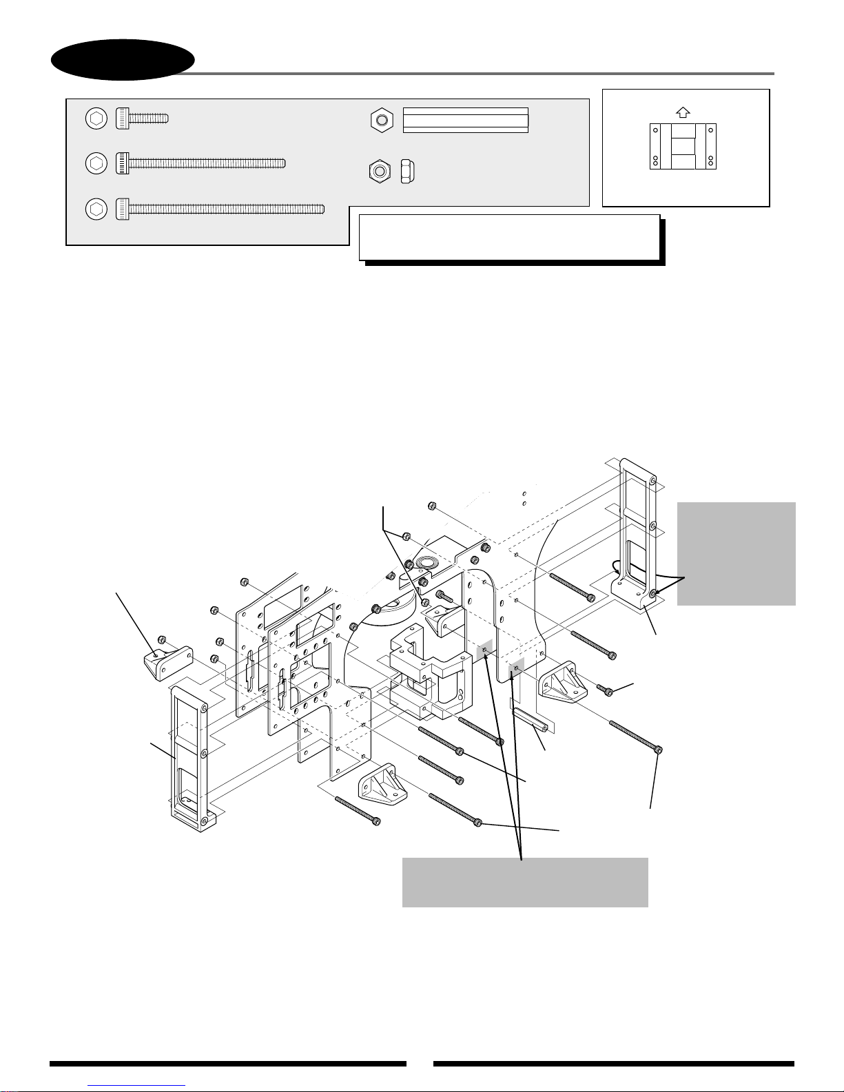
16
2-4
Socket Head Bolt, 3 x 10 mm
MAIN FRAME ASSEMBLY: ENGINE MOUNT/CROSS MEMBER INSTALLATION
................................2 pcs
Up
.....1 pc
Cross Member, 32 mm
Socket Head Bolt, 3 x 40 mm
Socket Head Bolt, 3 x 50 mm
A) Remove the two raised portions from cross member “B” as shown.
B) Remove a 1/2" x 3/4" portion of the clear coating from the inside of each
main frame as shown.
Landing Struts
Adaptor (4 pcs)
....6 pcs
.....2 pcs
Nylon Lock Nut, 3 mm
*TEAM TIP: Do not tighten bolts completly as this
time. These bolts will be tightened in Step 3-8.
Nylon Lock
Nut, 3 mm
(8 pcs)
.....................................8 pcs
O.S. Engines and YS Engines
Engine Mount Direction
Remove these two
raised portions
using a knife or
file so that they
are flush with
the cross member
side.
*
Cross Member B
(note direction)
3/4"
1/2"
*
*
*
*
Remove a 1/2" x 3/4" portion of the clear
coating from the inside of each frame
plate as shown.
Cross Member, 32 mm
Socket Head
Bolt, 3 x 40 mm
(6 pcs)
*
Socket Head Bolt, 3 x 50 mm (2 pcs)
Cross Member B
(note correct direction)
*
Socket Head
Bolt, 3 x 10 mm (2 pcs)
*
(Do not use threadlock.)
*
Page 17
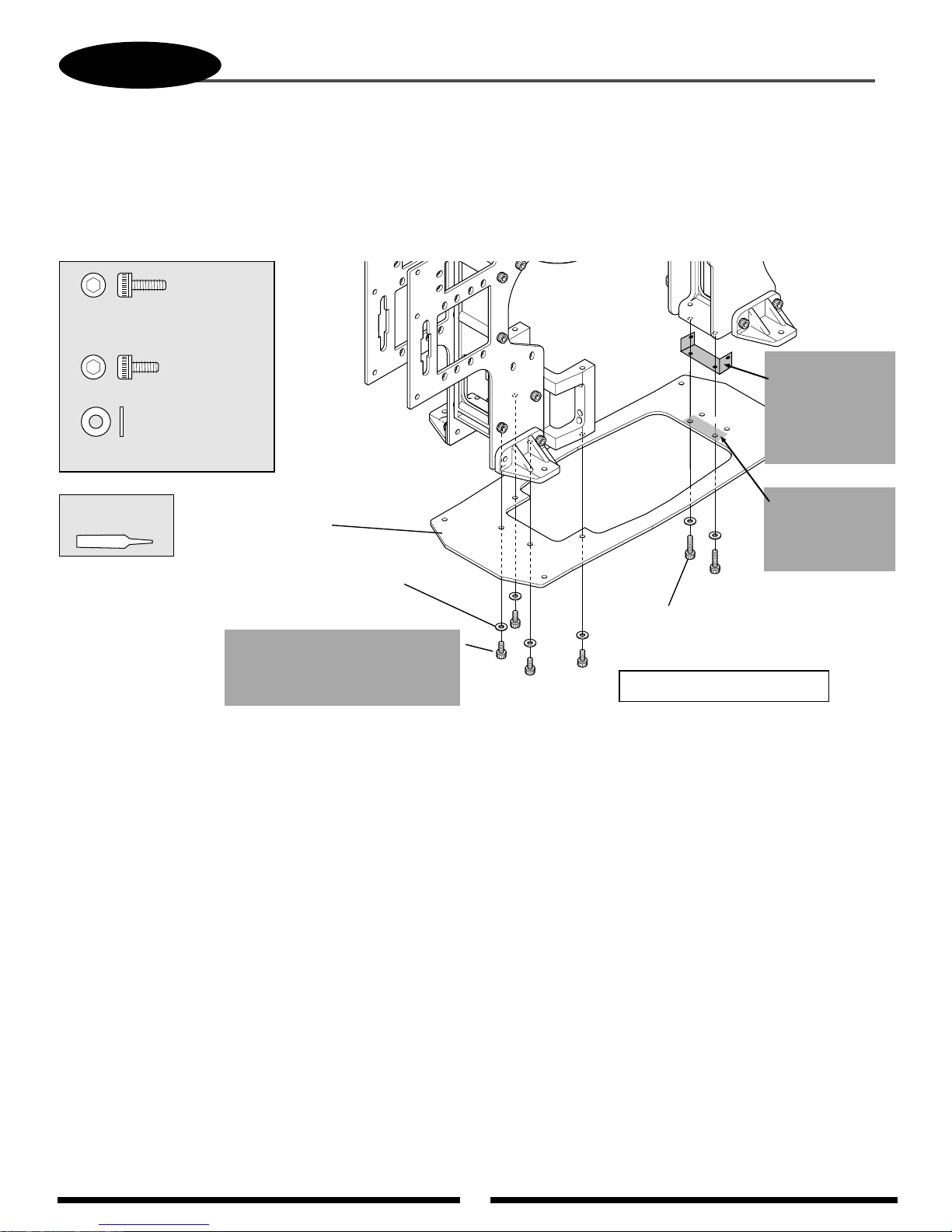
17
2-5
A) Remove a 3/4" x 11/4" portion of the clear coating from the top of the bottom carbon fiber plate as shown.
B) Insert the brass RF grounding plate between the cross member “B” and the inside of the two main frames as shown.
C) When installing the carbon bottom plate, replace the four 3 x 6 mm socket head bolts that connect the carbon plate to
the motor mount with the four 3 x 8 mm socket head bolts included with the RF grounding plate.
..............2 pcs
Socket Head Bolt, 3 x 8 mm
(included with the
grounding plate)
................4 pcs
Socket Head Bolt, 3 x 6 mm
..........................6 pcs
Flat Washer, 3 mm
MAIN FRAME ASSEMBLY: BOTTOM PLATE INSTALLATION
3/4"
1-1/4"
Insert the brass RF
grounding plate so
it’s positioned
between the cross
member “B” and
the two main
plates.
Use Red
Threadlock
When properly installed, the RF grounding plate will make contact with both the two main frames and the bottom
carbon plate in the areas where the clear coating has been removed. This will properly complete the ground between
the main frame and the bottom carbon plate.
Carbon Fiber
Bottom Plate
Flat Washer, 3 mm (6 pcs)
Socket Head Bolt, 3 x 6 mm (4 pcs)
Replace the 3 x 6 mm bolts with
the 3 x 8 mm bolts included with
the RF grounding plate.
Socket Head Bolt, 3 x 10 mm (2 pcs)
*
*
*
*
(included in kit)
*
Tighten bolts at this time.
*
Remove a 3/4" x
13/4" portion of
the clear coating
from plate as
shown.
Page 18
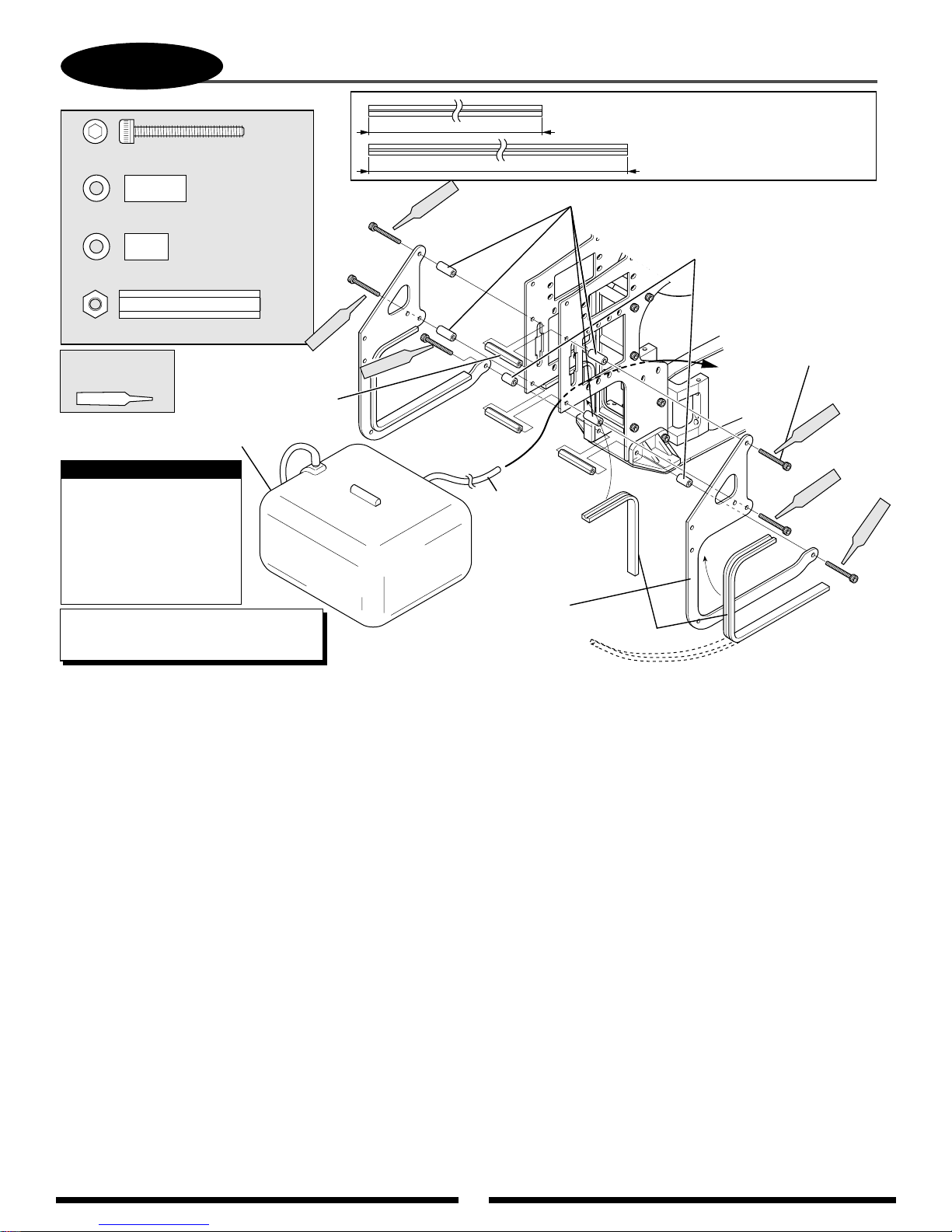
18
2-6
Socket Head Bolt, 3 x 25 mm
Spacer, 3 x 6 x 14 mm
FUEL TANK INSTALLATION
....6 pcs
...................4 pcs
Red
* Cut the tank mounting rubber to
120 mm
Spacer, 3 x 6 x 14 mm (4 pcs)
a length as shown from the two
pieces included with the kit.
210 mm
.......................2 pcs
Spacer, 3 x 6 x 10 mm
3 pcs
Cross Member, 32 mm
Use Red
Threadlock
Cross Member,
*
32 mm (3 pcs)
Fuel Tank
* Note:
If a YS engine is to be
used, replace the
existing tank mounting
rubber with Aerotrend
large fuel tubing or
equivalent.
*
TEAM TIP: Insert 32 mm crossmembers
before installing the fuel tank.
Red
Red
Attach fuel
line to tank
prior to
installation.
Tank Frame
* Tank Mounting Rubber
Spacer, 3 x 6 x 10 mm (2 pcs)
Socket Head
Bolt, 3 x 25 mm (6 pcs)
ed
R
Red
Red
Page 19
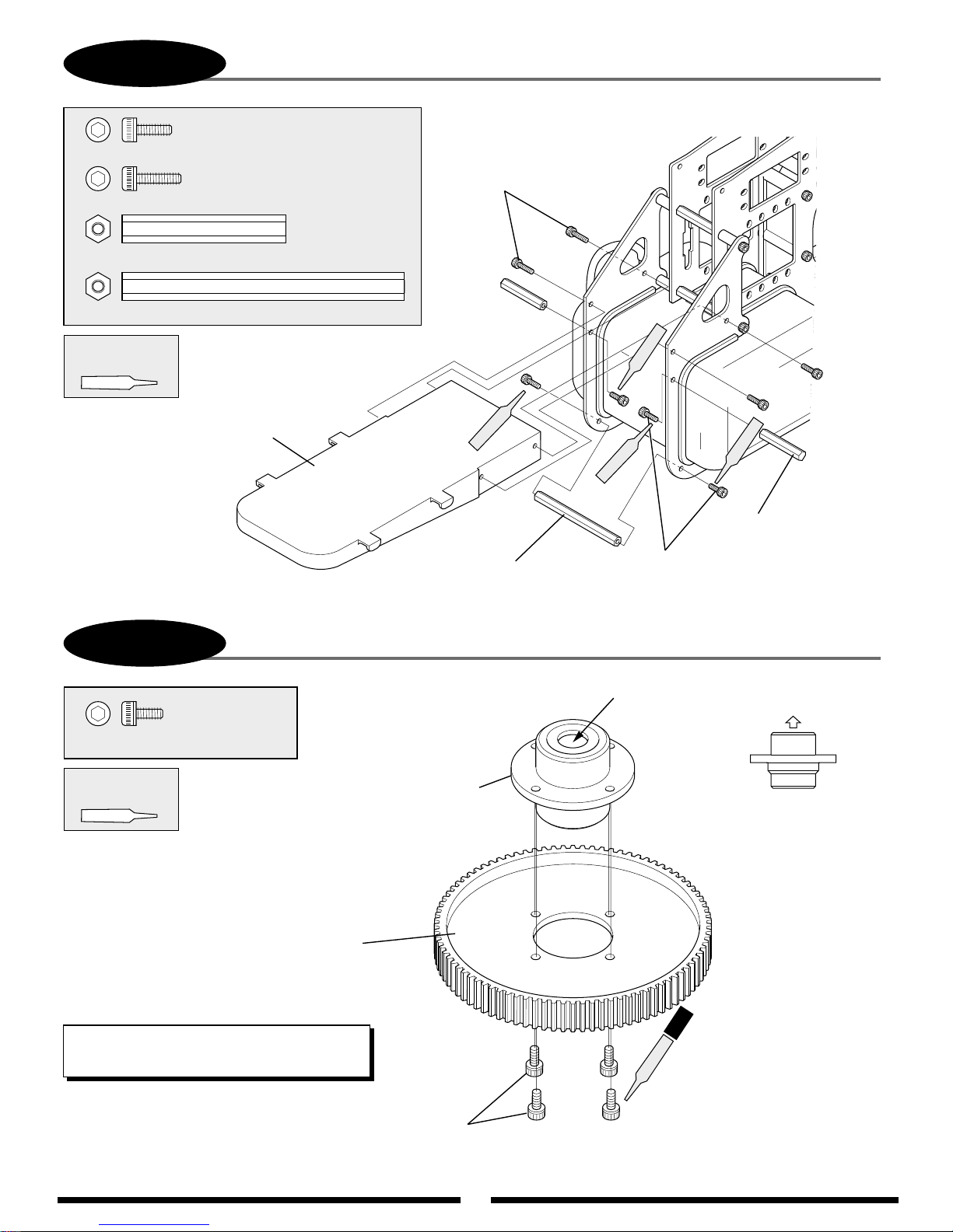
19
2-7
FRONT RADIO BED INSTALLATION
3-1A
MAIN DRIVE GEAR/AUTOROTATION ASSEMBLY
Socket Head Bolt 3 x 8mm
Socket Head Bolt, 3 x 6 mm
Main Drive Gear
Autorotation Assembly
Autorotation Assembly
Direction
(Note correct direction
during assembly.)
Socket Head Bolt, 3 x 6 mm (4 pcs)
(Tighten equally to prevent warping of main drive gear)
Socket Head Bolt, 3 x 8 mm (4 pcs)
Socket Head Bolt, 3 x 10 mm (4 pcs)
Socket Head Bolt 3 x 10 mm
Body Mounting Standoff 32 mm
Body Mounting
Standoff, 32 mm (2 pcs)
Cross Member 64 mm
Cross Member, 64 mm
Front Radio Bed
................................................4 pcs
..............................................4 pcs
...................2 pcs
...................4 pcs
.......1 pc
Up
*Apply a light
coating of grease to
torrington bearing.
Use Red
Threadlock
Use Red
Threadlock
*TEAM TIP: Apply a light coating of high speed
grease to the inside of the torrington bearing.
Red
Red
Red
Red
Red
4pcs
Page 20
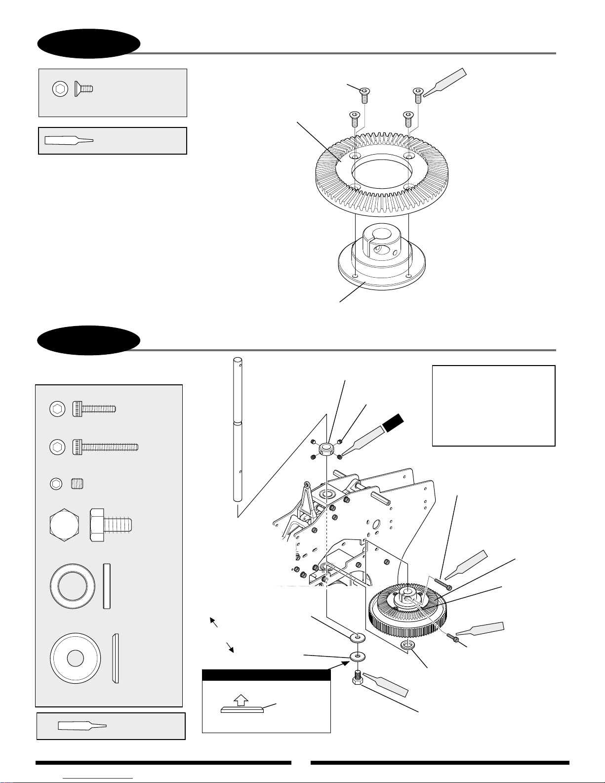
20
3-1B
BEVEL GEAR ASSEMBLY
Flat Head Bolt, 3 x 6 mm (4 pcs)
...................... 4 pcs
Flat Head Bolt, 3 x 6 mm
Use Red Threadlock
Attach the bevel gear hub as shown.
Be sure not to overtighten the four 3 mm bolts
as this could distort the bevel gear.
3-2
MAIN SHAFT/MAIN DRIVE GEAR INSTALLATION
Red
Bevel Gear
Bevel Gear Hub
..... 1 pc
Socket Head Bolt, 3 x 12 mm
... 1 pc
Socket Head Bolt, 3 x 20 mm
........................4 pcs
Set Screw, 4 x 4 mm
......1 pc
Hex Head Bolt, 6 x 10 mm
...............1 pc
Steel Washer, 10 x 16 x 2.5 mm
...........1 pc
Main Shaft Washer
Use Red
Threadlock
Special Washer, 10 x 6 x 0.5 mm
Both washers fit below
bottom bearing block.
Main Shaft Washer
Note:
Up
Bevel Cutting
Main Shaft Washer Direction
Main Shaft Collar
Set Screw
4 x 4 mm (4 pcs)
Red
4 pcs
Red
Assembly Steps
1. Secure the bottom 6 x 10 mm
bolt to the shaft.
2. Pull up on the shaft and secure
the main shaft collar using the
4-4 mm set screws.
3. Secure the bevel gear assembly.
Socket Head
Bolt, 3 x 20 mm
Red
Main Drive
Gear Assembly
Red
Socket Head Bolt, 3 x 12 mm
Washer, 10 x 16 x 2.5 mm
(fits between bottom bearing
and auto-rotation unit)
Hex Head Bolt, 6 x 10 mm
Bevel Gear
Assembly
Page 21
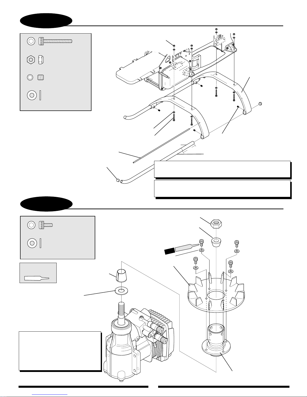
21
3-3
LANDING GEAR ASSEMBLY INSTALLATION
...4 pcs
..........................4 pcs
............................8 pcs
Socket Head Bolt, 3 x 20 mm
Socket Head Bolt, 3 x 20 mm (4 pcs)
Nylon Lock Nut, 3 mm
Nylon Lock Nut, 3 mm (4 pcs)
Flat Washer, 3 mm
Flat Washer, 3 mm (8 pcs)
.........................4 pcs
Set Screw, 4 x 4 mm
Set Screw, 4 x 4 mm (4 pcs)
Antenna Tube
Landing Skid (2 pcs)
Landing Struts (2 pcs)
Landing Skid Cap
Use CA adhesive
to attach.
TEAM TIP: The four 3 x 20 mm landing gear bolts can be installed
from the top (opposite diagram) for a cleaner appearance.
TEAM TIP: The landing skid tubes can be shortened by 3" to save
weight and provide a cleaner apearance. — Len
TEAM TIP: The landing skid tubes can be shortened by 3"
to save weight.
3-4
COOLING FAN/HUB INSTALLATION
Socket Head Bolt, 3 x 6 mm
Socket Head Bolt, 3 x 6 mm (4 pcs)
..................4 pcs
4 pcs
Nut (supplied with engine)
Washer
(supplied with engine)
Use for O.S. engines
only. Omit for YS
engines.
Taper Collet Upper (small)
Taper Collet Lower
(large)
...........................4 pcs
Flat Washer, 3 mm
Flat Washer, 3 mm (4 pcs)
Cooling Fan
Blades
Cooling Fan Hub
Use Red
Threadlock
*
*
*
*
*
Tighten bolts evenly
to prevent warping.
TEAM TIP: It is recommended that a
piston locking tool be used to properly
secure the fan assembly to the engine.
When using a piston locking tool, it is
necessary to also hold the fan assembly
to prevent excess loads from being
applied to the piston.
3"
Shorten
(optional)
Red
Page 22
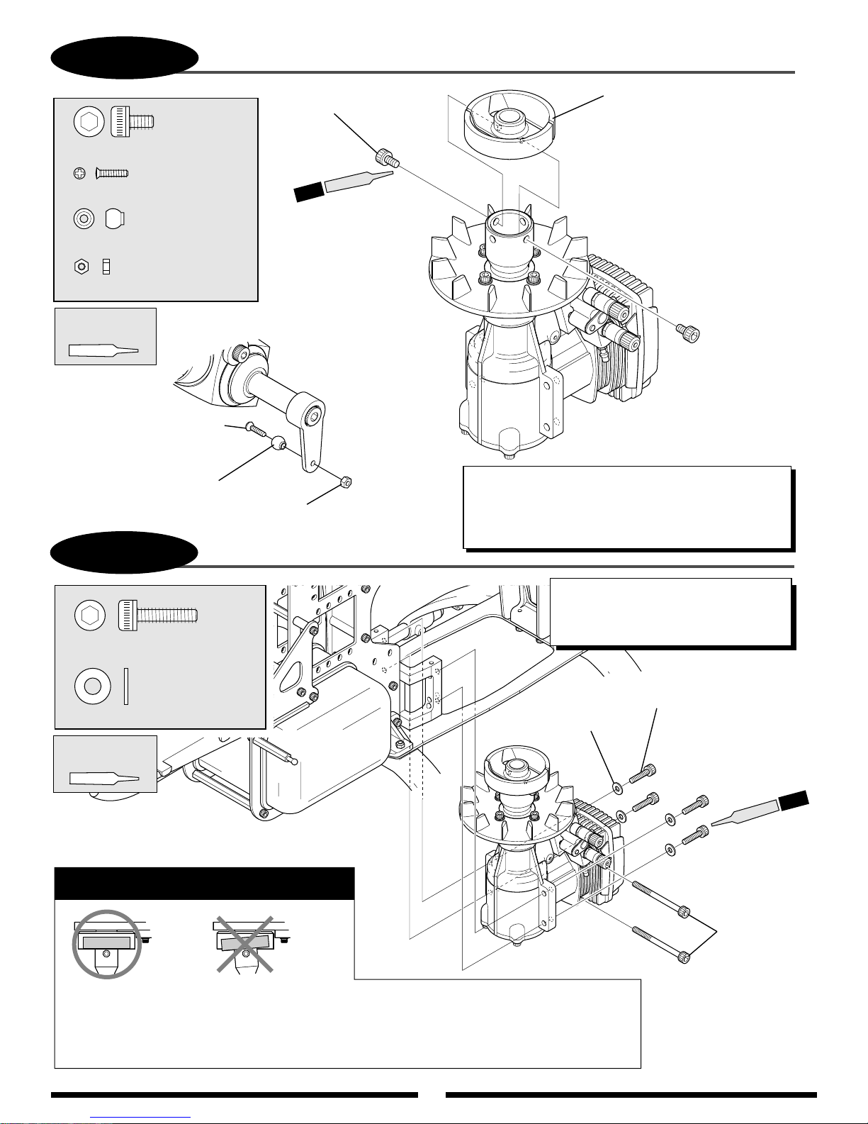
22
3-5
CLUTCH ASSEMBLY ATTACHMENT
............2 pcs
Socket Head Bolt, 4 x 6 mm
.....................1 pc
Flat Head Screw, 2 x 8 mm
......................1 pc
Steel Joint Ball
..........................1 pc
Hex Nut, 2 mm
Use Red
Threadlock
Flat Head Screw, 2 x 8 mm
Steel Joint Ball
Hex Nut, 2 mm
3-6
ENGINE INSTALLATION
Socket Head
Bolt, 4 x 6 mm (2 pcs)
Red
2 pcs
Clutch Assembly
TEAM TIP: Before the clutch is permanently attached,
rotate the clutch/fan assembly to check for trueness.
If any clutch runout is detected, reposition the clutch
at 90° intervals through the use of the four holes in the
fan hub until optimum clutch trueness is achieved.
TEAM TIP: The engine can be installed
.....4 pcs
Socket Head Bolt, 4 x 15 mm
........................4 pcs
Flat Washer, 4 mm
Use Red
Threadlock
Caution: Be sure to note the
correct installation of the engine.
1. Adjust the position of the engine as shown so the bottom of the clutch assembly is flush with
the bottom of the clutch bell. Also check to insure that the engine and clutch bell are parallel.
2. It is highly recommended that you insert the muffler bolts into the engine case prior to
installing the engine in the frame.
Flat Washer, 4 mm (4 pcs)
either from the bottom or from the side
of the frame. It may be easier to
install the engine from the side.
Socket Head Bolt, 4 x 15 mm (4 pcs)
4 pcs
Red
Muffler Bolts
(not included)
Page 23

23
3-7
.............8 pcs
Self Tapping Screw, 3 x 12 mm
.........................8 pcs
Flat Washer, 3 mm
Note:
Do not tighten screws at this
time. They will be tightened in
Step 3-9.
COOLING FAN SHROUD BRACKET ATTACHMENT
Cooling Fan Shroud Brackets (2 pcs)
Flat Washer, 3 mm (8 pcs)
3-8
Use Red
Threadlock
*
Once the engine has been installed, adjust the gear mesh of
the main pinion so that a slight amount of “backlash” is
achieved. One method for achieving the proper clearance is to
insert a folded piece of paper between the two gears, press the
gears together, then secure the bearing blocks in place. When
setting the gear mesh, make sure that the pinion gear remains
parallel to the main drive gear teeth, as it is possible to alter the
pinion gear angle during adjustment.
If you find difficulty achieving proper alignment of the
pinion, it is also possible to loosen the six bolts that attach the
engine mount to the main frame. This will allow the engine/
mount to be repositioned to achieve the proper gear mesh.
Once the desired gear mesh has been achieved, tighten all
loose bolts from Step 2-1. Please remember to use thread-lock
on the bolts securing the upper start shaft pinion block.
Please also remember to apply threadlock and tighten the
two 3 x 14 mm socket head bolts that connect bearing block
“A” to bearing block “B” . (see Step 1-1 for details).
Bolt Tightening Order:
1. Motor Mount to Main Frame Plates
2. Start Shaft Bearing Block/Bearing Blocks “A” & “B”
3. Crossmember “A”, and front Crossmember “B” to Main Frame Plates
4. Upper Main Shaft Bearing Block to Main Frame Plates
5. Rear Crossmember “B” to Main Frame Plates
6. Tighten all remaining bolts on frame left loose from Steps 2-1, 2-2, and 2-4
Gear Mesh Adjustment
BOLT TIGHTENING ORDER/GEAR MESH ADJUSTMENT
Self Tapping Screw, 3 x 12 mm (8 pcs)
Tighten all
6
remaining bolts.
4
*
*
2
5
TEAM TIP: Once the gear mesh/engine alignment
has been established, rotate the start shaft assembly
first counterclockwise, then clockwise. When moved
clockwise, the start shaft assembly should move
freely with little or no resistance. If resistance is
present, the clutch/start shaft assembly are not
aligned properly. Readjust as necessary.
3
1
Page 24
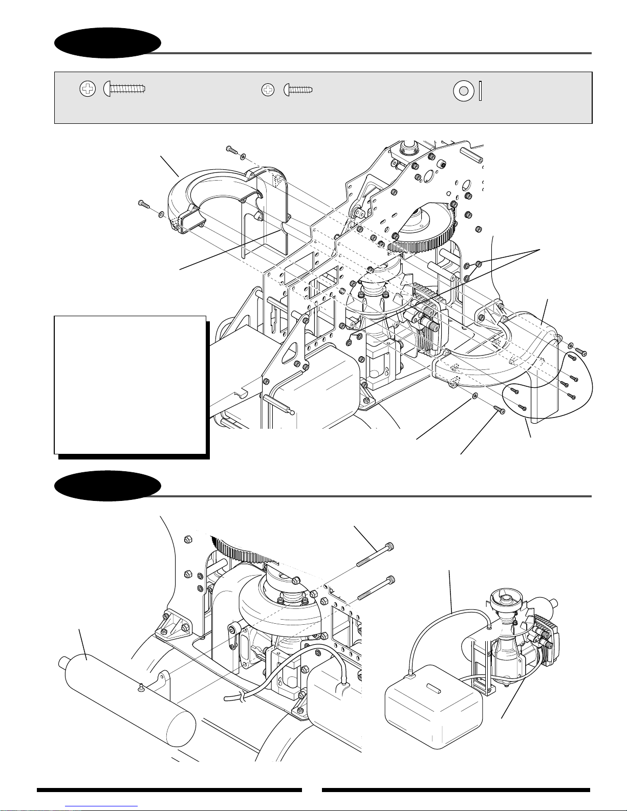
24
3-9
COOLING FAN SHROUD INSTALLATION
...4 pcs
Self Tapping Screw, 3 x 12 mm
Cooling Fan Shroud (Right)
Glow Plug Opening
(can be enlarged if
necessary)
TEAM TIP: The best alignment
of the fan shroud can be achieved
by attaching only the right half of
the shroud. Next, align the
mounts so the shroud is centered
around the fan. Tighten the fan
mounts then attach the left
half of the shroud. With some
engines and Ni-starters, you
may need to trim the glow plug
opening in the shroud for
additional clearance.
........6 pcs
Self Tapping Screw, 2.6 x 8 mm
Flat Washer, 3 mm (4 pcs)
Self Tapping Screw, 3 x 12 mm (4 pcs)
................4 pcs
Flat Washer, 3 mm
Tighten after right
shroud half has
been aligned.
Cooling Fan
Shroud (left)
Self Tapping Screw,
2.6 x 8 mm (6 pcs)
3-10
.60-Size Muffler
(not included)
For muscle pipe
installation, please refer
to the muscle pipe instructions
for proper mounting.
INSTALLATION OF THE MUFFLER/FUEL LINE CONNECTIONS
Muffler Bolts
Pressure Fuel Line Attachment
(not included)
Fuel Line Connection
Main Fuel Line
(Connect to carburetor.)
Page 25

25
4-1
SWASHPLATE ASSEMBLY
.............................4 pcs
Flat Head Screw, 2 x 10 mm
.................................4 pcs
....................................4 pcs
..........................3 pcs
Steel Joint Ball
Joint Ball Spacer, 2.75 mm
Use Red Threadlock
on all screws
Set Screw, 3 x 3 mm (3 pcs)
Joint Ball
Spacer, 2.75 mm
Steel
Joint Ball
Flat Head Screw,
2 x 10 mm (4 pcs)
Joint Ball Spacer, 2.75 mm (4 pcs)
(note correct direction)
140/120 Aluminum
Swashplate Assembly
Steel Joint Ball (4 pcs)
140 CCPM Swash Type
Long Control Ball, 20 mm (2 pcs)
Short Control Ball,
4 mm (1 pc)
120 CCPM Swash Type
Short Control Ball,
4 mm (3 pcs)
Control Ball, 20 mm (140 CCPM)
Control Ball, 4 mm
...2 pcs
.....................................1 pc
Set Screw, 3 x 3 mm
If there is play between the upper and lower swashplate,
tighten set screw 3 x 3 mm to the lower of swashplate
little by little.
*CAUTION : Do not tighten too much.
Note:
Page 26

26
4-2
SWASHPLATE/WASHOUT INSTALLATION
WASHOUT ASSEMBLY
Up
Washout Assembly
(preassembled)
Swashplate
Long Flange
Install onto the main rotor shaft
so the longer portion of the
washout base faces downward
toward the swashplate.
Page 27
27
4-3
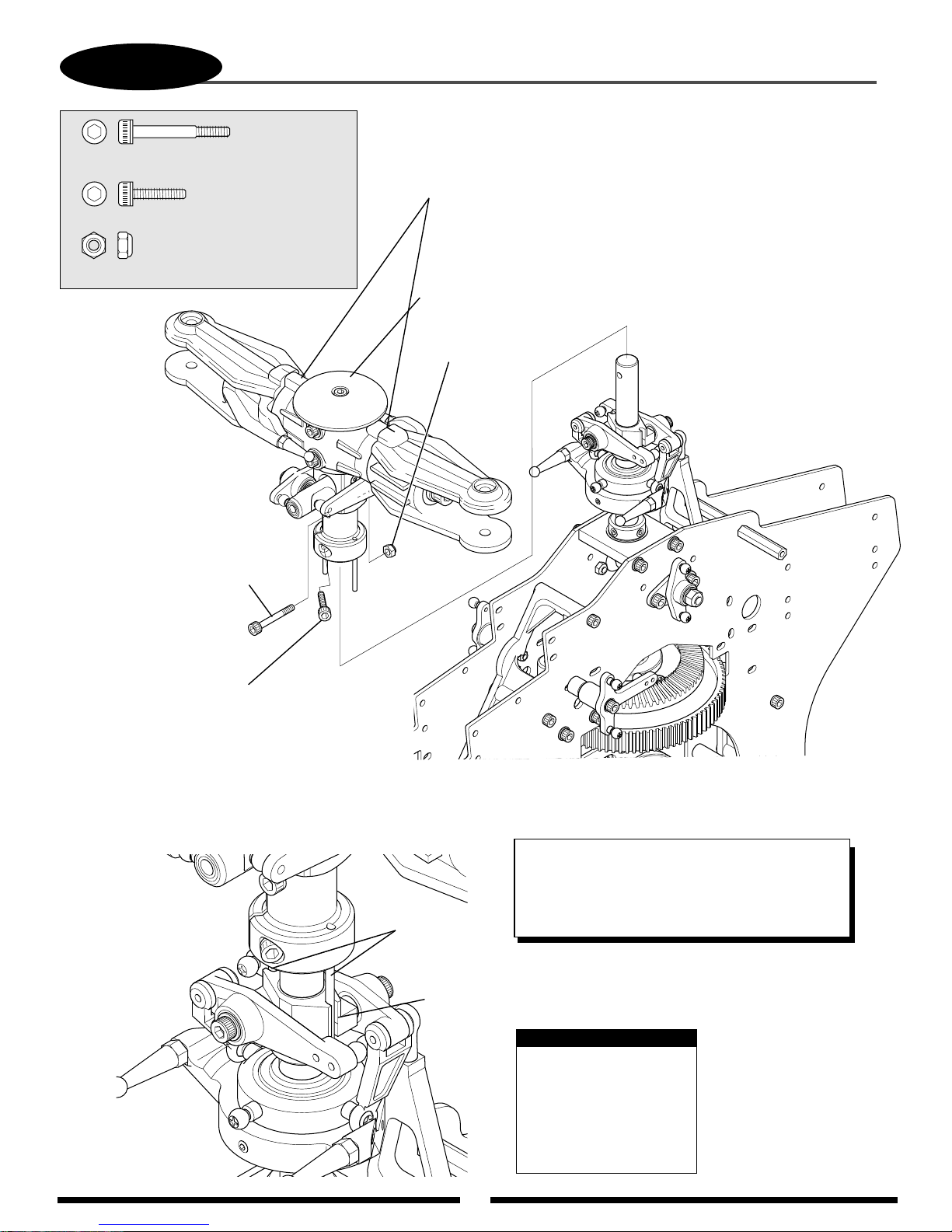
Special Socket Head Bolt, 3 x 22 mm
(Long Shank)
Socket Head Bolt, 3 x 12 mm
.............................................1 pc
Nylon Lock Nut, 3 mm
ROTOR HEAD INSTALLATION
...................1 pc
...............................1 pc
Main Rotor Head Dampeners Maintenance
The main rotor head dampeners should be inspected after 30 to
50 flights and replaced as needed. When replacing the dampeners,
it is also suggested that the thrust bearings be greased using a
high speed grease to prolong bearing life.
Rotor Head Assembly
(preassembled)
Nylon Lock Nut, 3 mm
Socket Head Bolt, 3 x 22 mm
Socket Head Bolt, 3 x 12 mm
Rotor Head
Pins (2)
Washout Base Driver
TEAM TIP: For safety, it’s important to note that a
hardened bolt with a long shank should be used to
attach the rotor head. We have seen many people,
over time, replace these with standard bolts. This
increases the chances of failures in flight.
Note:
Be sure to engage the
rotor head pins (2) into
the washout base driver
before securing the
rotor head assembly
in place.
Page 28
28
4-4
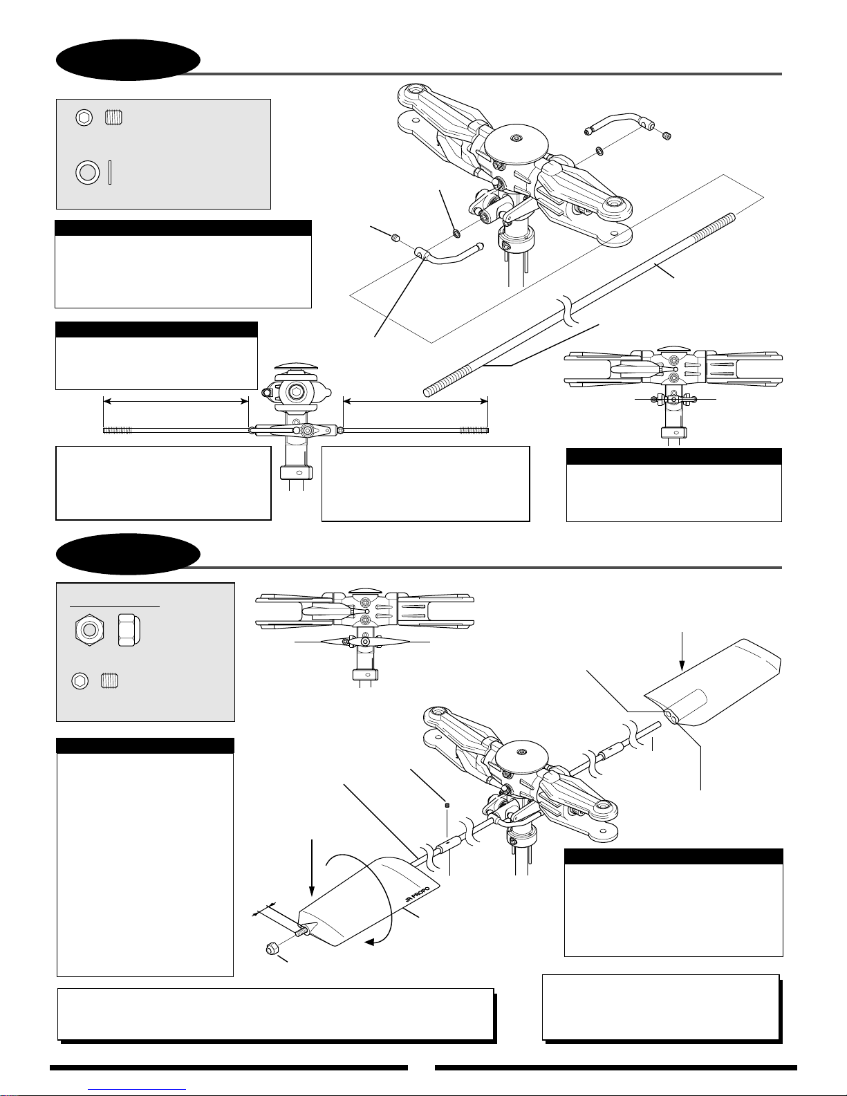
............................2 pcs
Set Screw, 4 x 4 mm
FLYBAR INSTALLATION
...............................2 pcs
Washer, 4 x 6 x 0.5 mm
Note:
™
Your Vigor
flybar paddle combinations, so the cyclic
rate of the model can be adjusted for
the desired “feel” or control response.
Center the flybar in the seesaw
shaft before securing the two
flybar control arms.
Version #1 Flybar 610mm (long)
Red Control Paddles
This will provide a slow to
moderate cyclic rate. This is ideal
for contest or smooth 3D type flying.
CS includes two sets of
Caution:
Equal Distance
4-5
FLYBAR PADDLE ATTACHMENT
Washer,
4 x 6 x 0.5 mm (2 pcs)
Set Screw,
4 x 4 mm (2 pcs)
Flybar Control Arm
Equal Distance
Version #2 Flybar 450mm (short)
Grey Control Paddles
This will provide a moderate to
high cyclic rate. This is ideal for
smooth or agressive 3D type flying.
Flybar, 610 mm
(Version #1 long)
Flybar, 450 mm
(Version #2 short)
Caution:
Check to insure that the two
flybar control arms are parallel
to the center line of the flybar.
Version #1 only
............2 pcs
Nylon Lock Nut, 4 mm
...................2 pcs
Set Screw, 4 x 4 mm
Version #1 Note:
Thread each flybar paddle
onto the flybar until the
threaded tip of the flybar
protrudes approximately
5 mm. Adjust each flybar
paddle so they are parallel
to the flybar control arms
and to each other. Secure to
the flybar using two 4 mm
nylon lock nuts. Note proper
direction of each flybar
paddle (short portion
forward, clockwise rotation).
TEAM TIP: Flight tune your Vigor to achieve the desired cyclic rate by moving
the flybar weights in and out on the flybar (in=more cyclic rate, out=less).
Make sure that they are set to the same distance or vibration can occur.
Align paddles
so they are parallel
to each other.
Set Screw,
4 x 4 mm (2 pcs)
610 mm Flybar
VERSION #1
5 mm
Nylon Lock Nut, 4 mm (2 pcs)
(For version #1 only)
Flybar Weight
(2 pcs)
Flybar Paddles
(2 pcs) Red, Version #1
VERSION #2
Paddle threads onto
450 mm flybar.
Rear Hole:
Very agressive cyclic rate.
Not recommended
as the cyclic rate
will be excessive.
450 mm
Flybar
Front Hole:
Recommended for a
moderate to high
cyclic rate.
Version #2 Note:
Thread the grey paddle onto the
flybar approximately 25 mm.
Adjust each flybar paddle so they
are parallel to the flybar control
arms and to each other.
TEAM TIP: Use JB-weld (epoxy steel) to
glue the flybar paddles to the flybar. Still
use the nut as well. The glue prevents the
paddles from turning in flight.
Page 29
4-6
29
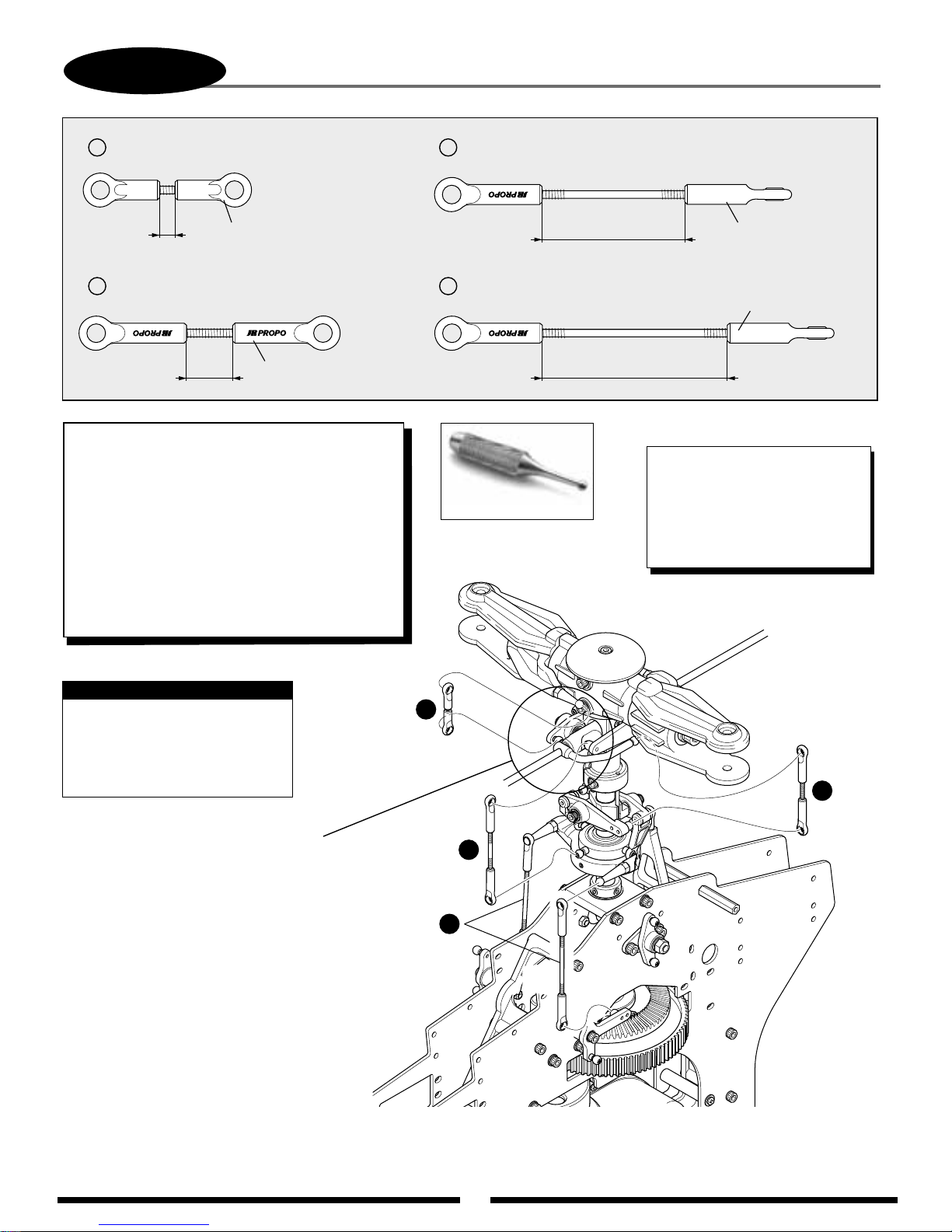
Use JR Ball Link
Sizing T ool
1
SEESAW ARM TO MAIN BLADE HOLDER
(Threaded Rod 2.3 x 15 mm)
SWASHPLATE/T-ARM CONTROL ROD INSTALLATION
3
SWASHPLATE TO SEESAW ARM
(Threaded Rod 2.3 x 50 mm)
................................2 pcs
3.5 mm
2 4
WASHOUT ARM TO FLYBAR CONTROL ARM
(Threaded Rod 2.3 x 30 mm)
Universal Ball Link (short)
.......2 pcs
Universal Ball Link
12.5 mm 42 mm
TEAM TIP: The JR ball links are designed with little
ridges around the lip of the link. These ridges, in
conjunction with the JR ball link sizing tool, are there
to help you custom fit the link to the ball. If the link
fits on the ball too tight, you can use the reaming tool
to enlarge the link hole size. If the link fits too loose
on the ball, you can push in on the ridges on the link
with a small pair of pliers. This reduces the size of the
link hole and makes the link fit tighter. JR links are
some of the best links available. It is important to note
that very little force is needed on the ridges to resize
the link. Using pliers on any other part of the link can
cause the links to break.
SWASHPLATE TO T-ARM
(Threaded Rod 2.3 x 60 mm)
....2 pcs
Universal Ball Link
32.5 mm
Universal Ball Link
....2 pcs
TEAM TIP: After many flights there
can be excess play between the
ball and link. It is usually the ball
that has actually worn. So when
replacing parts, you will actually
get the best results by replacing
the balls.
Caution:
Please note that all universal
links should be adjusted so that
when attached to the control
ball, the words “JR PROPO”
are to the outside.
Note: The seesaw mixing arms included
with the Vigor are designed to offer a
pitch range of approx. 20° (+11°, -9°).
If additional pitch range is required,
it is possible to replace these arms with
part #JRP960178B. These arms will
provide a total pitch range of 23°
(+13°, -10°). Please note that these
optional mixing arms will also increase
the “Bell” movement of the Rotor
Head, which will alter the flight
characteristics slightly. Also note
that if these optional arms
are used, the overall pitch and travel
values may vary from that shown
in the data sheets included
in this manual (page 53).
1
2
3
4
Page 30
5-1
30
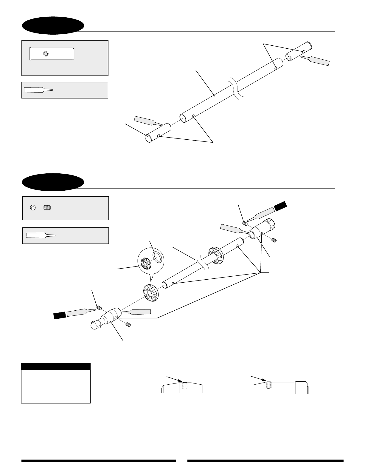
TAIL DRIVE SHAFT PREPARATION
Make sure that all holes are aligned.
......... 2 pcs
Aluminum Drive Pipe Insert
Use Green
Threadlock
Aluminum Drive Shaft Insert
5-2
..................... 4 pcs
Set Screw, 3 x 4 mm
Use Red & Green
Threadlock
TAIL DRIVE SHAFT ASSEMBLY
Green
O-ring
13.5 x 2.5 (2 pcs)
Aluminum Drive Shaft, 794.5 mm
Make sure that all holes are aligned.
Set Screw, 3 x 4 mm (2 pcs)
Green
Green
2 pcs
ed
R
Set Screw, 3 x 4 mm (2 pcs)
Red
2 pcs
Aluminum Drive Joint, Front
Note:
When secured, the 4 mm
set screws should be
nearly flush with the
outside surface.
Drive Shaft
GuideBearing
(2 pcs)
Set Screw, 3 x 4 mm
Aluminum Drive
Joint, Rear
Make sure that all holes
are aligned.
Green
Set Screw, 3 x 4 mm
Page 31
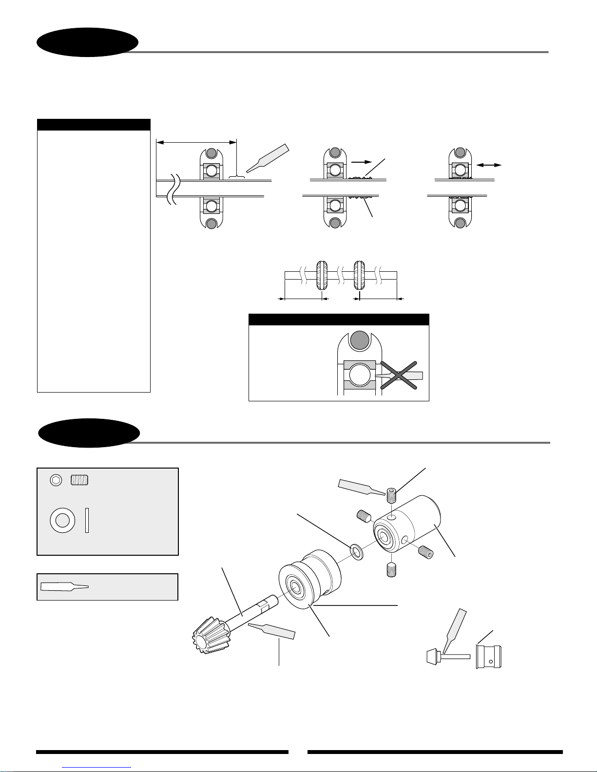
31
5-2
continued
DRIVE SHAFT GUIDE BEARING ATTACHMENT
Follow this procedure when attaching:
Note:
Use Poly Zap
(not included) to attach
bearings to the drive shaft.
Once the Poly Zap
is applied and the guide
bearings are in their
correct positions
(260 mm/230 mm),
the Poly Zap can be
quick cured using
Zip Kicker.
Position the shaft
assembly on a flat
surface before/while
the Poly Zap is curing.
It is very important
that the guide bearings be
attached to the shaft at
non equal measurements
as shown to prevent
resonance vibration
and fatigue.
Step A
Front
260 mm/230 mm
Rear
Step B Step C
Wipe lightly
Poly Zap
Bearing Positions
260 mm 230 mm
Note:
Do not apply
Poly Zap to
inside of ball
bearings.
w/finger or towel.
Poly Zap
Lightly oil bearings after the glue has dried.
Poly Zap
Slide and spread.
5-3
..................... 4 pcs
Set Screw, 4 x 6 mm
........................1 pc
Washer, 5 x 9 x 1 mm
Use Green
Threadlock
Attach the tail drive joint and
secure so that there is no
fore/aft movement of the shaft,
but the shaft will spin freely in
the bearing assembly.
BEVEL PINION GEAR ASSEMBLY
Green
Washer, 5 x 9 x 1 mm
Bevel Pinion Gear
Green
Bevel Pinion
Bearing Case
Apply a thin coating of green threadlock
to shaft pinion of assembly.
Set Screw, 4 x 6 mm (4 pcs)
Tail Drive Joint, Front
Flange must face bevel gear.
Green
Bevel Pinion Bearing Case Direction
Flange
Page 32
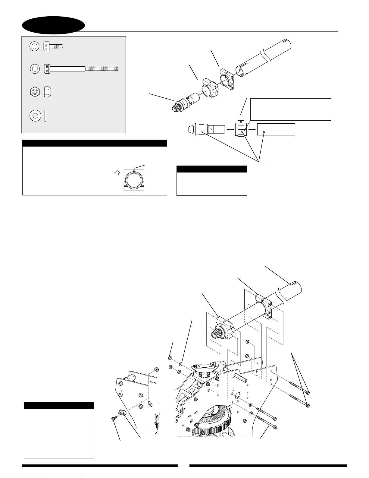
32
5-4
TAIL BOOM/BEVEL PINION GEAR INSTALLATION/ADJUSTMENT
........................... 1 pc
Socket Head Bolt, 3 x 8 mm
Socket Head Bolt, 3 x 40 mm
.................................. 3 pcs
Nylon Lock Nut, 3 mm
.................................... 4 pcs
Flat Washer, 3 mm
Note:
Install the tail boom holders
so the slotted side is toward
the top. Also, it's important
to make sure that the black
tail boom holder is at the
front of the tail boom as
shown.
... 2 pcs
Tail Boom Holder
Up
Aluminum Tail Boom Holder, Silver
Aluminum Tail Boom
Holder, Black
Bevel Pinion Gear
Assembly
Slot
The 2 3.5 x 6 mm bolts
included in this step are
not used.
Aluminum Tail Boom Holder, Black
Note proper direction during
installation as bottom hole is
offset to match frame.
Must be aligned.
Note:
BEVEL GEAR MESH ADJUSTMENT
Before tightening of the 4 tail
boom mounting clamp bolts, it
will be necessary to set the bevel
gear to bevel pinion gear mesh by
raising or lowering the tail boom
assembly.
To set the proper mesh, insert
1 thickness of paper (the same
thickness as the pages of this
manual) between the 2 bevel
gears.
Next, push the tail boom assembly
down so that there is no gear
backlash with the paper in place.
Tighten the 4 tail boom mounting
bolts. Next, remove the thickness
of paper and check the gear
mesh. There should be a very
slight amount of backlash. If the
backlash seems too much, repeat
this procedure using thinner
paper. If backlash can't be
detected, double the paper
thickness and retest.
Tail Boom, 879 mm
Aluminum Tail Boom Holder, Silver
Aluminum Tail Boom Holder, Black
Flat Washer,
3 mm (4 pcs)
Nylon Lock Nut,
3 mm (4 pcs)
*
It is better to set this
gear mesh slightly tight,
rather than loose, or
damage to the bevel
gear can occur during
extreme 3D flying or
tail blade contact with
the ground.
Note:
Socket Head
Bolt, 3 x 8 mm
Rod Guide
* Do not tighten bolts
*
until bevel gear mesh
*
has been adjusted.
Socket Head Bolt, 3 x 40 mm (2 pcs)
*
Page 33
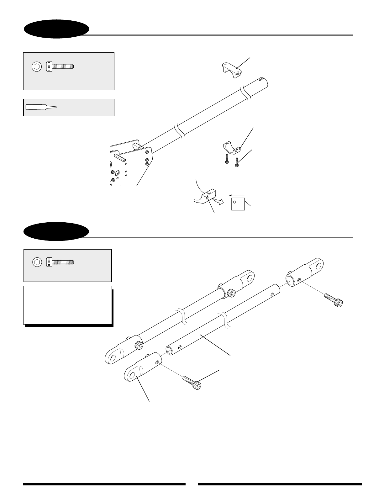
33
5-5
......... 2 pcs
Socket Head Bolt, 3 x 12 mm
Use Red Threadlock
TAIL SUPPORT CLAMP INSTALLATION
Aluminum Tail Support
Clamp, Upper
Aluminum Tail Support
Clamp, Lower
Socket Head Bolt,
3 x 12 mm (2 pcs)
*Do not tighten bolts
completely at this time.
FRONT
Note offset in bolt hole location.
Tail Support Clamp Direction
5-6
5-6
Socket Head Bolt, 2.6 x 12 mm
TEAM TIP: It is suggested that
the Tail Brace Connectors be
bonded to the Tail Brace Tubes
using either thick CA adhesive,
or JB Weld.
TAIL BOOM BRACE ASSEMBLY
...........4 pcs
Tail Brace Tube
Socket Head Bolt, 2.6 x 12 mm (4 pcs)
Tail Brace Connector (4 pcs)
Page 34

34
5-7
TAIL BRACE INSTALLATION
............. 2 pcs
Socket Head Bolt, 3 x 8 mm
......... 2 pcs
Socket Head Bolt, 3 x 12 mm
........................ 2 pcs
Flat Washer, 3 mm
2 pcs
Socket Head Bolt, 3 x 22 mm
Use Red Threadlock
Red
Aluminum Tail Support Clamp, Lower
Socket Head Bolt, 3 x 12 mm (2 pcs)
*Do not tighten bolts completely at this time.
Red
Socket Head
Bolt, 3 x 8 mm (2 pcs)
Flat Washer
3 mm (2 pcs)
Spacer, 3 x 8 x 6.5 mm (2 pcs)
Flat Washer, 3 mm (2 pcs)
2 pcs
Red
Socket Head Bolt
3 x 22 mm (2 pcs)
5-8
................ 2 pcs
Socket Head Bolt, 3 x 6 mm
............ 3 pcs
Socket Head Bolt, 3 x 8 mm
Socket Head Bolt, 3 x 22 mm
........................ 6 pcs
Flat Washer, 3 mm
Use Red Threadlock
HORIZONTAL/VERTICAL FIN INSTALLATION
Carbon Horizontal Fin
Tail Case Support B (Thin)
Socket Head
Bolt, 3 x 6 mm (2 pcs)
Flat Washer
3 mm (2 pcs)
1 pc
Red
2 pcs
Flat Washer
3 mm (4 pcs)
Position the
horizontal
fin so that it is
level to the building
surface (90° to the
main rotor shaft)
and tighten the 2 tail
support clamp bolts
left loose in Step 5-5.
Carbon Vertical Fin
Tail Case Support A (Thick)
Socket Head Bolt
3 x 8 mm (3 pcs)
Socket Head Bolt, 3 x 22 mm
* Do not tighten completely.
Keep vertical.
ed
R
4pcs
Page 35
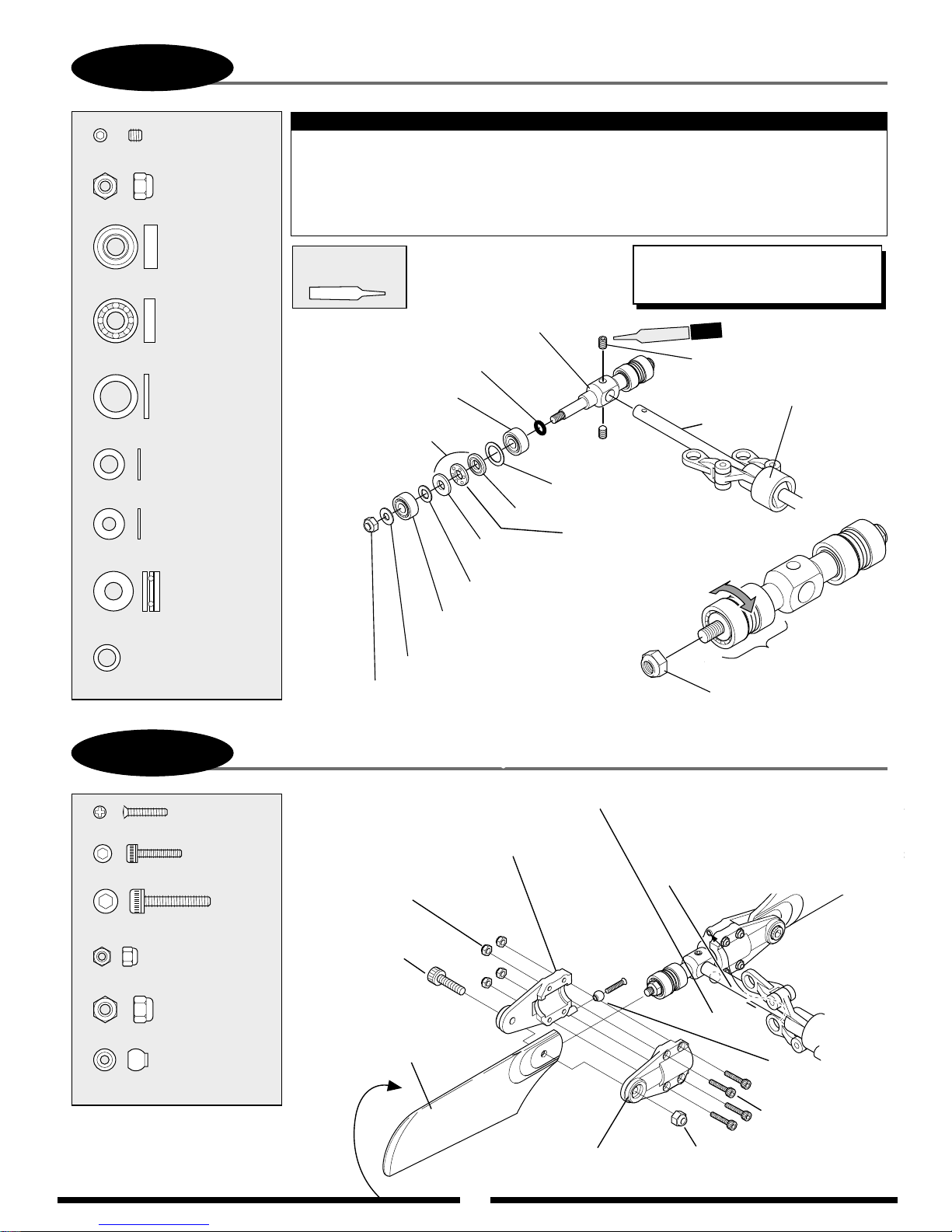
5-9
35
TAIL CENTER HUB ASSEMBLY
...................2 pcs
Set Screw, 3 x 3 mm
................2 pcs
Nylon Lock Nut, 3 mm
...............2 pcs
Bearing (sealed), 4 x 10 x 4 mm
...............2 pcs
Bearing (open), 4 x 10 x 3 mm
.................2 pcs
Washer, 7 x 10 x 1 mm
...................2 pcs
Washer, 4 x 7 x 0.5 mm
...................2 pcs
Flat Washer, 3 mm
Note:
Slide the tail slide ring assembly on the tail output shaft before installation of the tail
rotor hub. When attaching the tail rotor hub, be certain that the set screws 3 x 3 mm
engage into the holes at the end of tail output shaft. Use green threadlock.
Check to make sure the tail blade holder bearings can rotate freely, without play.
If binding occurs, loosen the 3 mm nylon lock nut.
Use Green
Threadlock
Tail Center Hub
O-Ring,
5 x 7 x 1 mm (2 pcs)
Bearing (sealed),
4 x 10 x 4 mm (2 pcs)
Thrust Bearing,
4 x 9 x 4 mm (2 pcs)
Washer,
7 x 10x 1mm (2 pcs)
Large I.D.
Apply grease.
Small I.D.
TEAM TIP: Use thin oil on the tail shaft
to lubricate the tail pitch slider. Also
apply grease to the tail thrust bearings.
2 pcs
Green
Set Screw, 3 x 3 mm (2 pcs)
Tail Slide Ring Assembly
Oil lightly
..............2 pcs
Thrust Bearing, 4 x 9 x 4 mm
........................2 pcs
O-Ring, 5 x 7 x 1 mm
5-10
..............2 pcs
Flat Head Screw, 2 x 10 mm
..........8 pcs
Socket Head Bolt, 2 x 10 mm
Socket Head Bolt, 3 x 15 mm
......................8 pcs
Nylon Lock Nut, 2 mm
..................2 pcs
Nylon Lock Nut, 3 mm
TAIL BLADE HOLDER ASSEMBLY
..2 pcs
Nylon Lock Nut, 3 mm
Flat Head Screw, 2 x 10 mm (2 pcs)
Tail Blade Holder w/Flange
Nylon Lock Nut,
2 mm (8 pcs)
Socket Head Bolt,
3 x 15 mm (2 pcs)
Washer,
4 x 7 x 0.5 mm (2 pcs)
Bearing (Open),
4 x 10 x 3 mm (2 pcs)
Flat Washer, 3 mm (2pcs)
Tail Blade
Holder Bearings
Nylon Lock Nut, 3 mm
Connect the tail pitch
links to the steel joint
ball after the tail
blade holders have
been assembled.
...................2 pcs
Steel Joint Ball
Rotation direction:
Be sure to note the correct
direction of the tail rotor
blades during assembly.
Tail Rotor Blade
Tail Blade Holder
Steel
Joint Ball (2 pcs)
Socket Head Bolt,
2 x 10mm (8 pcs)
Nylon Lock Nut, 3 mm (2 pcs)
Page 36
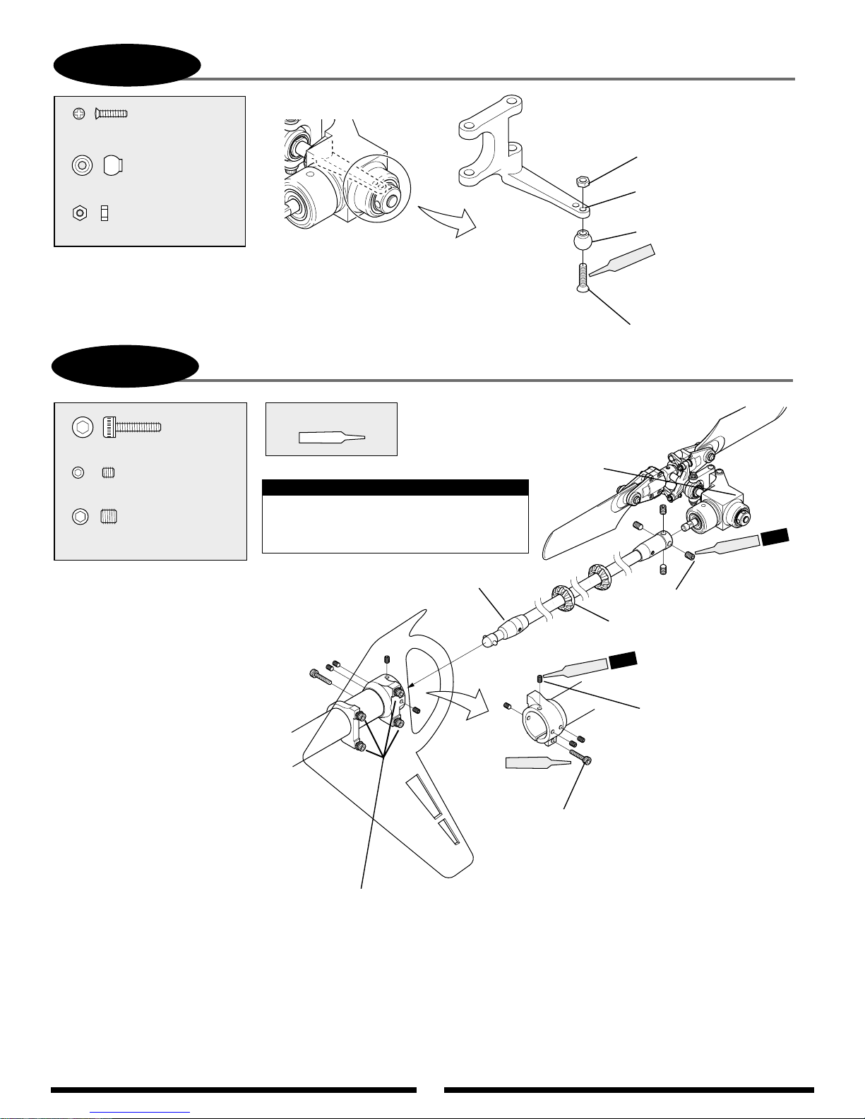
36
5-11
............. 1 pc
Flat Head Screw, 2 x 8 mm
................. 1 pc
Steel Joint Ball
..................... 1 pc
Hex Nut, 2 mm
STEEL JOINT BALL INSTALLATION
Hex Nut, 2 mm
Attach the steel joint ball to
the outside hole as shown.
Steel Joint Ball
Red
Flat Head Screw, 2 x 8 mm
5-12
............. 1 pc
Socket Head Bolt, 3 x 12 mm
.......................... 4 pcs
Set Screw, 3 x 3 mm
.......................... 4 pcs
Set Screw, 4 x 4 mm
Attach the tail drive shaft to the
tail gear box as shown using the
4–4 mm set screws (use
Threadlock). Please leave a very
slight space between the drive shaft
and the bearing of the tail gear box.
Next, apply a light coating of oil to
the drive shaft guide O-rings and
install the assembly into the tail
boom. To allow the tail gear box to
be fully inserted into the boom, it
may be necessary to rotate the
front bevel pinion gear so the drive
shaft can engage into the coupler.
Level the tail output shaft of the
tail gear box so that it is 90° to the
main rotor shaft, and lock the tail
gear box in place using the 3 mm
socket head bolts and 3 mm set
screws as shown.
TAIL DRIVE SHAFT/TAIL GEAR BOX INSTALLATION
Use Red Threadlock
Tail Gear Box Assembly
Note:
It will be neccessary to loosen the 4 bolts
holding the vertical fin to allow the tail
gear box to be inserted into the tail boom.
Tail Drive Shaft Assembly
Vertical
Fin
* Tighten after gear box has been aligned.
Socket Head Bolt, 3 x 12 mm
* Do not tighten completely until
the gear box has been positioned correctly.
Red
Red
4 pcs
Red
Set Screw, 4 x 4 mm (4 pcs)
*Apply a coating of light oil to
the O-rings of the drive shaft
guide bearing.
4 pcs
Set Screw, 3 x 3 mm (4 pcs)
Page 37
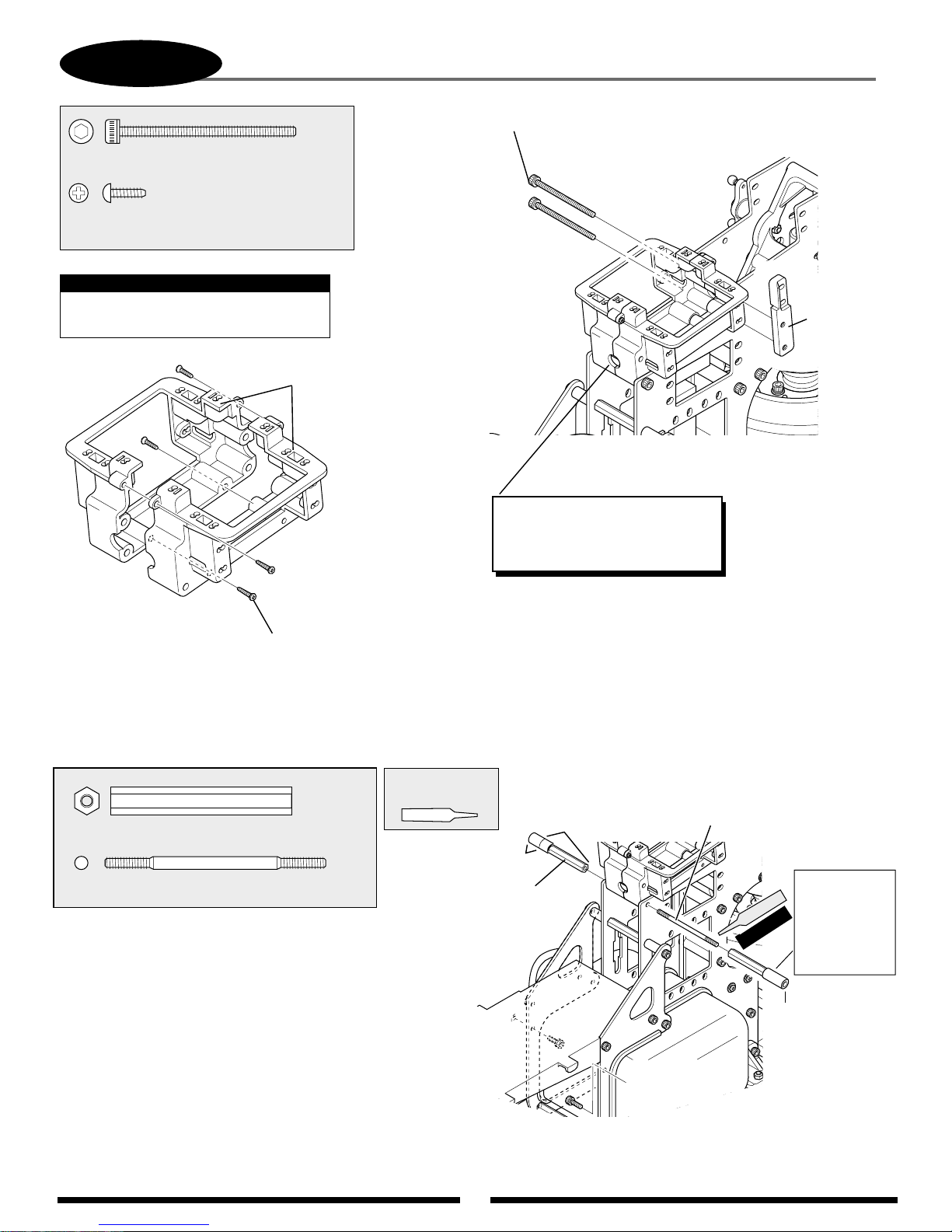
37
Socket Head
Bolt, 3 x 40 mm (2 pcs)
6-1
UPPER SERVO TRAY/BODY MOUNT ATTACHMENT
Socket Head Bolt, 3 x 40 mm
...3 pcs
Self Tapping Screw, 2.6 x 8 mm
..........................................4 pcs
When installing the servo tray, be
careful not to overtighten the screws.
Note:
Self Tapping
Screw, 2.6 x 8 mm (4 pcs)
Servo Tray
Both Si
des
Threaded Rod, 3 x 50 mm
Threaded Rod,
3 x 50 mm
..1 pc
Cross Member, 41 mm
........2 pcs
Cross Member
41 mm (2 pcs)
BODY MOUNT ATTACHMENT
Use Red
Threadlock
TEAM TIP: Increase the size of the
hole using a Dremel tool. This will
allow for easier insertion of the
servo leads.
Red
CCPM
Aluminum
Servo Mount
Standard
Fuel Tubing
(Not included;
use remaining
from engine/fuel
tank installation.)
8 mm
20 mm
Add two 20 mm
pieces of fuel tubing
to the standoffs as
shown so that they
protrude 8 mm
from the end of the
standoff. These will
support the canopy.
Page 38
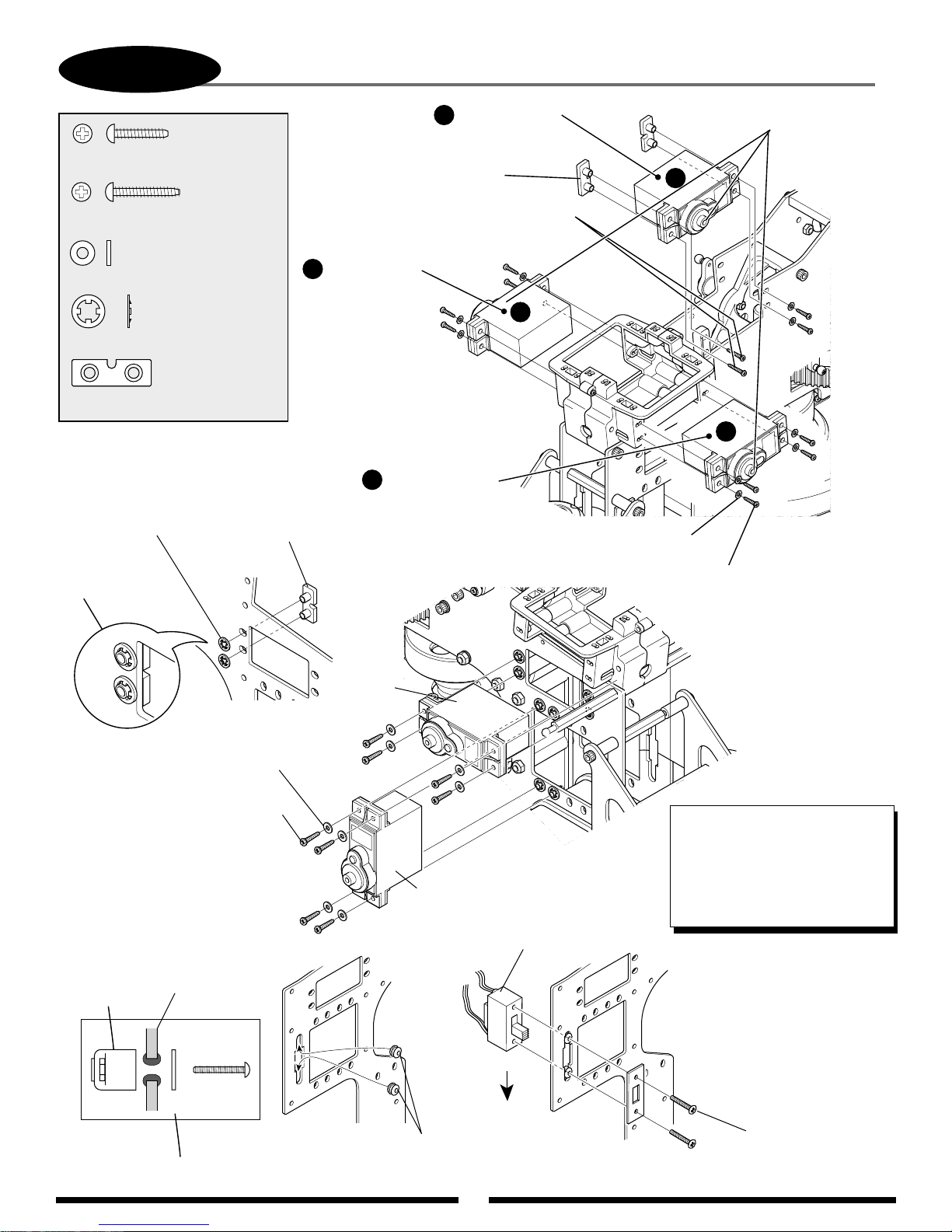
38
6-2
................20 pcs
Self Tapping Screw, 2.6 x 12 mm
Self Tapping Screw, 2.6 x 15 mm
...............................20 pcs
Flat Washer, 2.6 mm
SERVO/SWITCH HARNESS INSTALLATION
.............2 pcs
Elevator Servo
A
(Ch3)
Type-B Servo
Mounting Plate (2 pcs)
Self Tapping Screw, 2.6 x 15 mm (2 pcs)
*This portion only. (without washer)
C
Aileron Servo
(Ch2)
Note output
*
shaft direction.
A
...........................8 pcs
CA Stopper Ring, 3.5 mm
.......................4 pcs
Type-B Servo Mounting Plate
* Note correct servo
output shaft orientation
during installation.
CA Stopper Ring, 3.5 mm
Attach as shown.
Type-B Servo
Mounting Plate
Rudder
Servo
Collective Servo
B
(Ch6)
C
B
Flat Washer, 2.6 mm (10 pcs)
Self Tapping Screw, 2.6 x 12 mm (10 pcs)
Flat Washer, 2.6 mm (8 pcs)
Self Tapping
Screw, 2.6 x 12 mm (8 pcs)
Dampener Rubber
(2 pcs)
Switch
Switch Plate
Throttle
Servo
Off
On
Switch Dampener
Rubber (2 pcs)
TEAM TIP: When installing the
switch harness, position it so
that "Up" is off and "Down" is the
on position. This will prevent the
switch from accidentally being
turned off in a hard landing
or auto.
Switch Harness
Screws Supplied
with Switch
Page 39
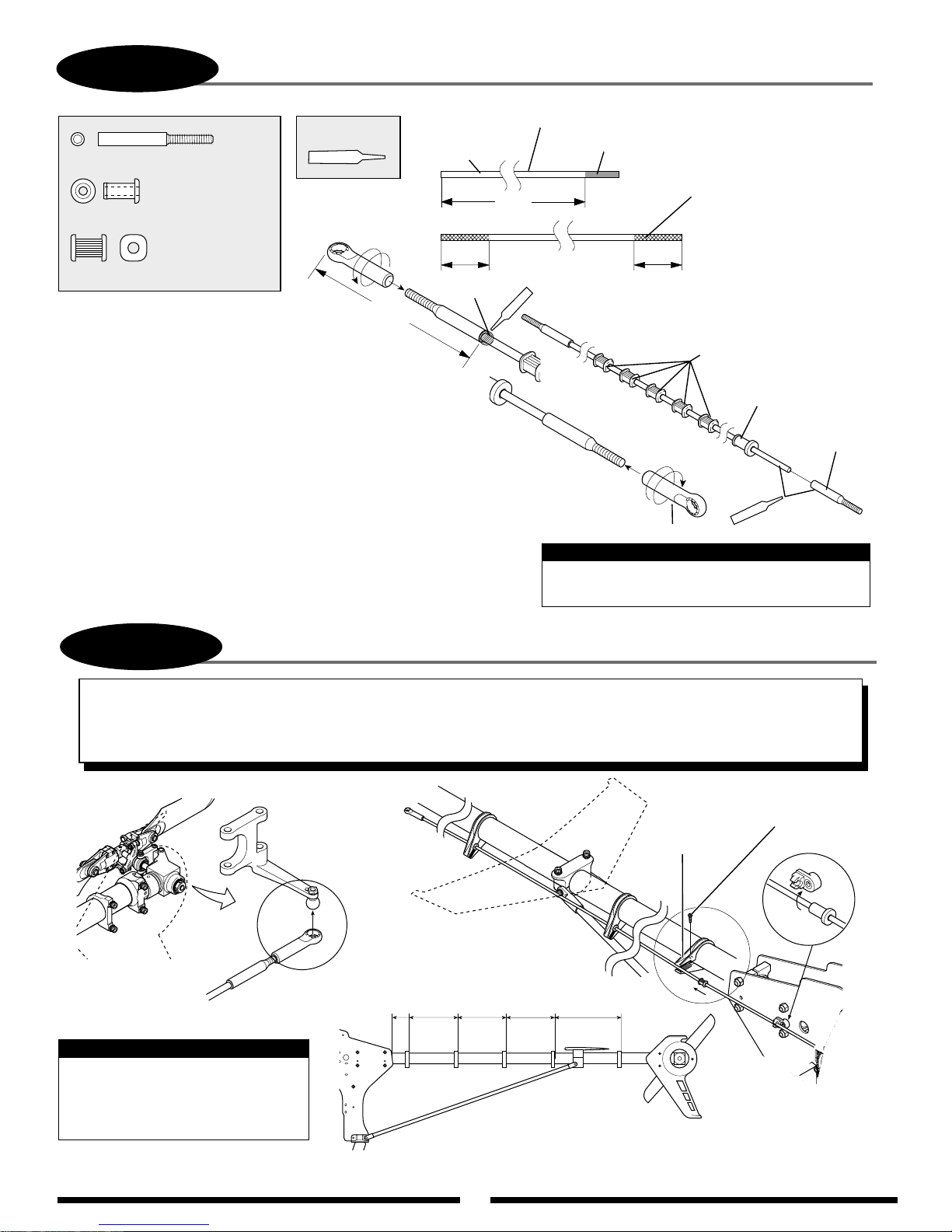
39
6-3
Rod End
TAIL CONTROL ROD ASSEMBLY
... 2 pcs
Use JB Weld
Carbon Tail
Control Rod
Cut the carbon tail control rod to the length shown.
Cut unnecessary portion.
....................... 1 pc
Tail Rod Guide Collar (round)
................... 5 pcs
3
/4"
Tail Rod Guide Collar (square)
JB Weld Fillet
42 mm
ASSEMBLY PROCEDURE
1) Cut the control rod to the correct length.
2) Sand each end as shown and test fit the two steel
rod ends. Make sure that rod is sanded so that it
is undersized. This will allow the JB Weld to
remain on the rod for proper adhesion.
3) Slide the tail rod guides onto the rod and keep in
place using masking tape on each end of the rod.
4) Thread the universal links onto the steel rod ends as shown.
5) Apply JB Weld epoxy to each end of the rod where it has been
sanded and attach the two steel rod ends. Make an additional
fillet of JB Weld at the back of each steel rod end as shown for
proper adhesion.
6) Let assembly set on a flat surface until the JB Weld has cured.
401/4"
JB Weld
Sand each end of the rod as
shown. It will be necessary
to reduce the diameter
slightly to allow proper
insertion into the steel rod
3
/4"
end and also to allow space
for the JB Weld
®
to contact each part.
Tail Rod Guide
Collar (Square) (5 pcs)
Tail Rod Guide Collar
(Round) (1 pc)
Screw on 8 mm
Universal Link (2 pcs)
Steel Rod End
(2 pcs)
eld
JB W
Use JB Weld to attach.
Note:
The tail control rod final adjustment will need
to be made prior to the first flight.
6-4
TAIL CONTROL ROD/TAIL GUIDE ATTACHMENT
TEAM TIP: Once tail guides are attached to the tail boom, check to insure that the tail control rod will move freely with little
resistance. Rotate the tail guides as needed until the system moves as easily as possible. Once this has been achieved,
apply a small amount of CA adhesive to bond the tail guides to the tail boom. This will prevent the guides from moving
accidentally during flight. Apply oil to the rod and guides after assembly.
Self Tapping Screw,
2 x 8 mm
(5 pcs)
Tail Rod Guide
(5 pcs)
TAIL GUIDE SPACING
60 mm 130 mm 140 mm 145 mm
Note:
Once this assembly has been
completed, adjust the tail control
rod as needed for proper tail rotor
blade pitch prior to the initial flight.
160 mm
Page 40
40
6-5
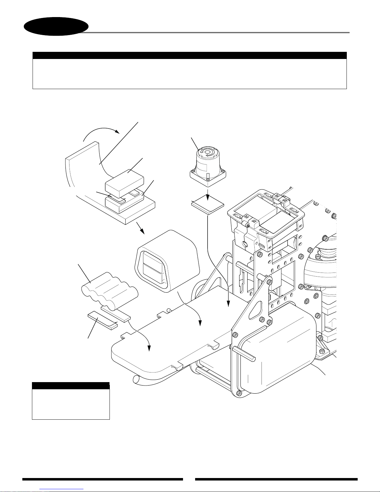
Be certain when installing the gyro unit to the front radio bed that it does not come in contact with the frame of the
helicopter, etc. Also make sure that the front radio bed is free from oil and debris. Clean with rubbing alcohol if
necessary to insure proper adhesion.
Double-Sided Servo Tape
GYRO/RECEIVER/BATTERY INSTALLATION
Note:
Sponge/Foam Rubber
Gyro Unit
Gyro Amplifier
Receiver
Wrap the receiver/gyro
amplifier in sponge or
foam rubber to protect
from vibration.
Ni-Cd RX Battery Pack
1400mAh
minimum
Double-Sided Servo Tape
Note:
Double-sided servo tape
and sponge/foam rubber
are not included in this kit.
Page 41

41
The following preparations are suggested for use with JR
®
radio systems. However, these procedures are applicable to most other
brand radio systems. These suggested adjustments are necessary to insure correct installation and attachment of the control linkages
and servo horns.
TRANSMITTER PREPARATION
RECEIVER FLIGHT PACK PREPARATION
SERVO HORN INSTALLATION SUGGESTIONS
1. Set all trim levers, knobs, and switches to the neutral or
zero positions.
2. Turn the transmitter power switch to the On position.
3. Reset all functions and input values of your computer
radio system to the factory preset position.
4. Move the throttle/collective control stick to the center or half
stick position. Next slide the throttle trim lever to the full low
position.
1. With the transmitter still on, slide the receiver switch to its
On position. All servos should move to the neutral or
center position.
2. Check that all servos operate with the appropriate
control stick.
3. Rest the throttle stick to the center position, making sure
the throttle trim is still at low.
4. Turn off the receiver switch first, followed by the transmitter.
For proper operation, it’s important that the servo horns are
positioned on the servos in the “exact” neutral position. Although
most computer radio systems offer a sub-trim feature, it is
suggested that the servo horns be manipulated on the servos to
achieve the “exact” neutral settings.
Since the servo output spline on a JR system has an odd number
of teeth (21), it’s possible to reposition the servo arm on the servo
at 90° intervals to achieve the proper neutral attachment of the
servo horn.
Once the correct arm of the servo horn has been established,
it’s suggested that the remaining unused arms be removed from
the servo horn as shown in the installation diagrams in the
following section.
It will also be necessary to enlarge the appropriate hole in the servo
horn slightly to allow correct installation of the steel control balls to
the servo horn.
RADIO SYSTEM PREPARATION
Page 42
42
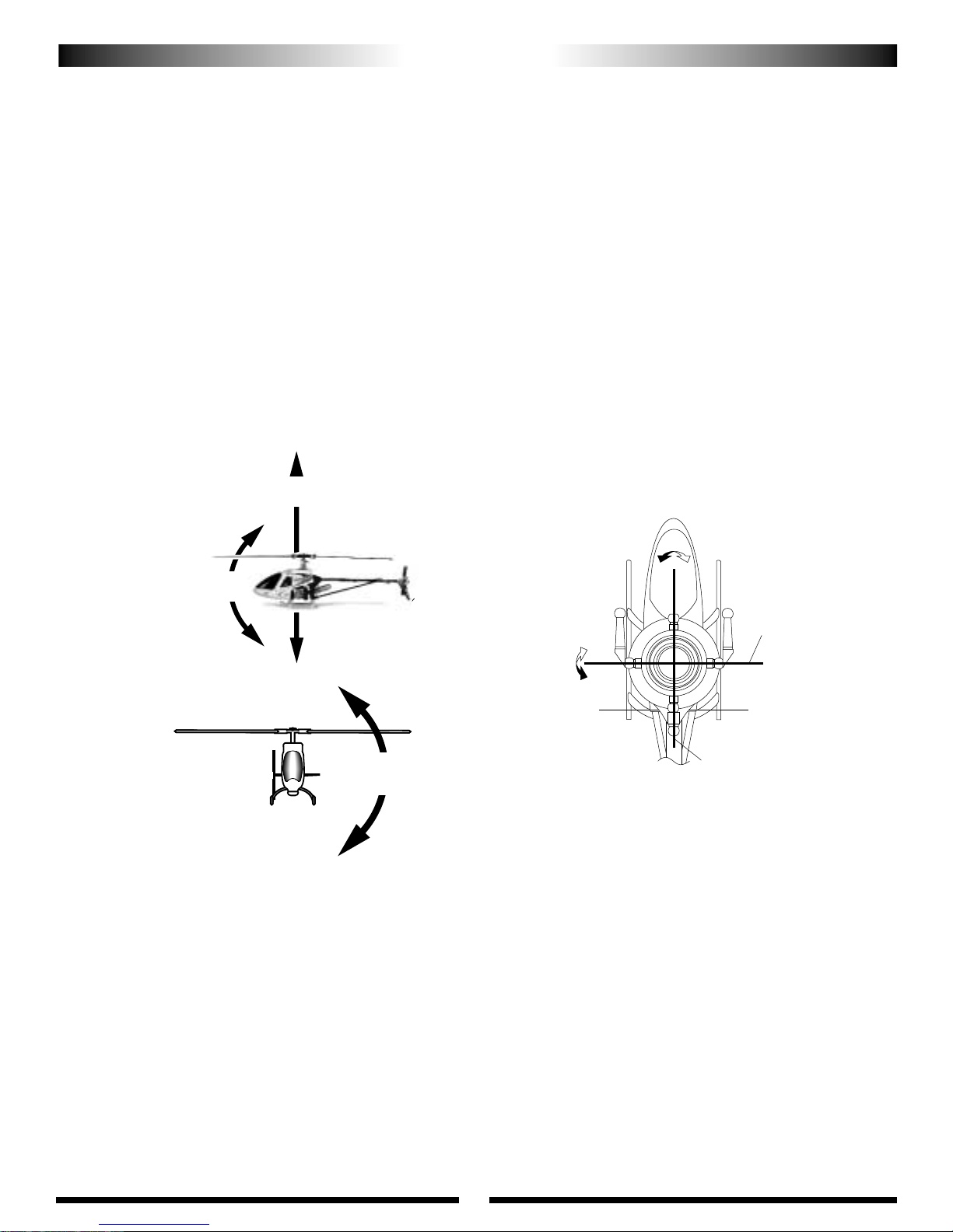
120/140 3-SERVO CCPM SWASHPLATE MIXING
The JR®120°/140° CCPM or Cyclic/Collective Pitch Mixing system offers the user a control system that can accomplish the
same control inputs as a one servo standard system, but with increased precision and reduced complexity.
As with the one servo system, the JR CCPM system utilizes three servos for the three main controls: aileron (roll),
elevator(pitch), and collective. The CCPM lower swashplate ring is designed with only three control balls, spaced at 120° or
140° from each other, hence the 120°/140° CCPM designation. Although the control balls are not at 90° as in the standard
system, the aileron (roll) axis is still parallel to the main mechanics of the helicopter, and the elevator (pitch) axis still functions
at 90° to the mechanics as does the one servo system. Please refer to the diagram below for clarification.
The main difference in the way that these two systems operate is that unlike the one servo system where the three servos
work completely independent from each other, the CCPM systems work as a team to achieve the same control inputs. For
example, if an aileron (roll) input is given, two servos work together to move the swashplate left and right. If an elevator (pitch)
input is given, all three servos work together to move the swashplate fore and aft. For collective, it’s also the strength of three
servos that will move the swashplate up and down the main rotor shaft. With two or three servos working at the same time
during any given control input, servo torque is maximized and servo centering is also increased. In addition to these benefits,
CCPM achieves these control responses without the need for complex mechanical mixing systems that require many more
control rods and parts to set up.
This amazing CCPM control is achieved through special CCPM swashplate mixing that is preprogrammed into many of
today’s popular radio systems. Since the 120° and 140° CCPM function is preprogrammed, CCPM is no more complicated to set
up than a conventional one servo standard system. When you factor in the reduced parts count and easy programming, CCPM is
actually easier to set up and operate than many conventional systems.
For JR radio owners, please refer to the radio information contained at the front of this manual or on the following pages to
determine if your radio system has the CCPM function. For other brands of radio systems, please contact the radio manufacturer
for CCPM information. Please note that it is not possible to program a non-CCPM radio system for CCPM operation.
UNDERSTANDING CCPM CONTROL SYSTEMS
ElevatorAxis
140°
JR 120°/140° 3 Servo CCPM Control System
Aileron Axis
Pitch Axis
ElevatorAxis
Aileron Axis
Page 43
43
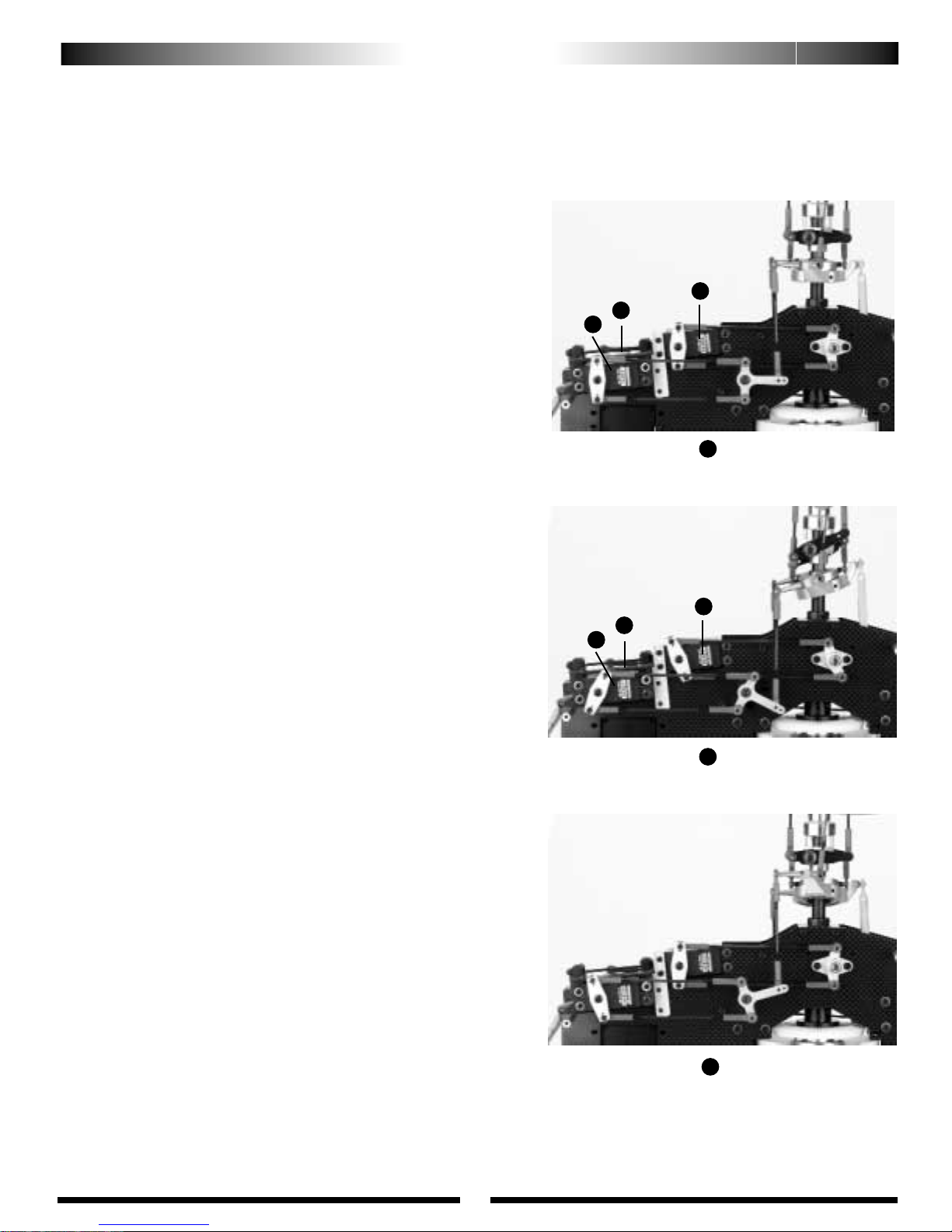
The JR 120°/140° three servo CCPM relies on the radio’s
special CCPM swashplate mixing, rather than a conventional
mechanical mixer that is utilized to achieve the same results.
The radio’s 120° or 140° 3-servo CCPM function automatically mixes the three servos to provide the correct mixing
inputs for aileron (roll), elevator (pitch), and collective. The
following is an example of how each control input affects the
servo’s movement.
1. COLLECTIVE
When a collective pitch input is given, all three servos
(A, B, and C) move together in the same direction, at equal
amounts, to raise and lower the swashplate while keeping the
swashplate level. During this function, all three servos travel
at the same value (100%) so that the swashplate can remain
level during the increase and decrease in pitch. As mentioned,
this mixing of the three servos is achieved through the radio’s
CCPM program.
2. ELEVATOR (PITCH)
When an elevator input is given, all three servos must move
to tilt the swashplate fore and aft, but their directions vary.
The two front servos (B and C) move together in the same
direction, while the top servo (A) moves in the opposite
direction. For example, when a down elevator (forward cyclic)
command is given, the two front servos (B and C) will move
rearward, while the top servo (A) moves foreward so that the
swashplate will tilt forward. During this function with 120°
CCPM, the top servo (A) travels at 100%, while the two front
servos (B and C) travel at 50% (1/2the travel value) of the top
servo. This difference in travel is necessary due to the fact that
the position of the 120 CCPM rear control ball is two times
the distance of the two front control ball position as measured
from the center of the swashplate. With 140° CCPM selected,
all three servos travel at 100%, eliminating elevator trim
changes during quick collective inputs. This mixing of the
three servos is also achieved through the 140° CCPM program
only found in JR 10X systems.
3. AILERON (ROLL)
When an aileron (roll) input is given, the two front servos
(B and C) travel in opposite directions, while the top servo (A)
remains motionless. For example, when a right aileron (roll)
command is given, the left front servo (C) will move forward,
while the right front servo (B) will move backward to tilt the
swashplate to the right. As mentioned, the top servo (A) will
remain motionless. The travel value for each of the two rear
servos is 100%.
HOW JR®120/140 CCPM WORKS
Collective Movement
1
A
B
C
Elevator Movement
2
Aileron Movement
3
A
B
C
Page 44
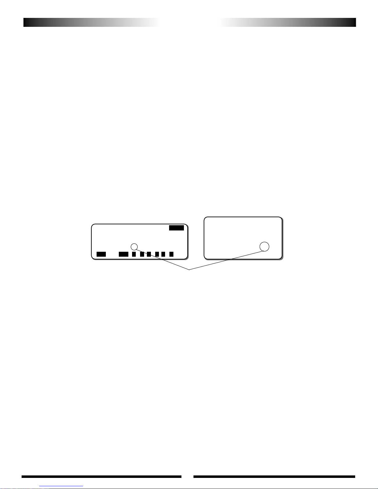
44
IMPORTANT CCPM PROGRAMMING DOS AND DON’TS
It is extremely important that the travel adjustment values for the three CCPM servos (aileron, elevator, Aux 1) be initially set to
exactly the same travel value. If the travel value is not similar for each servo, it will create unwanted pitching and rolling of the
swashplate during collective pitch inputs. The travel values for each servo will be adjusted in Step 7.8 and Step 7.9 to remove any
minor pitch and roll coupling during pitch, roll, and collective movements.
Minor travel value adjustments are necessary due to slight variations in servo travel and centering. Although the three servos may
appear to travel at the same amounts in each direction, in reality the servos can vary slightly. This variation is more common in analog
type servos. If JR’s new digital servos are used, the travel adjustment values will generally not need to be altered.
A. TRAVEL ADJUST
It is also extremely important that the servo reversing directions for the three CCPM servos (aileron, elevator, Aux 1) be set as
indicated in the upcoming radio programming steps. If one or more servos is not set to the correct direction, the CCPM function will
be out of synchronization, and the three control functions (Aileron, Elevator, Collective) will not move properly. In the event that a
control surface is working in the wrong direction, the control function can only be reversed by changing the desired CCPM value for
that function from a (+) to a (-) value or vise versa.
Example: If when you increase the collective pitch, the pitch of the main blades actually decreases, it will be necessary to access the
CCPM function and change the travel value for this function from (+) to (-), or (-) to (+). This will reverse the direction of the
collective pitch function without affecting the movement of the aileron and elevator functions.
B. SERVO REVERSING
[SWASH TYPE]
3SERVOS(120•)
EXP AILE ELEV PITCH
[NH +48% +52% +60%
ENTER
SEL ACT + –CL+ –CL+ –
CL
To reverse the direction of a CCPM control
function, it’s neccessary to change the value
from (+) to (–) or (–) to (+) as needed.
10 Series Systems
[SWASH MIX]
3servos
120
•
AILE +48%
ELEV +52%
∞ PIT. +60%
8103 Systems
Page 45
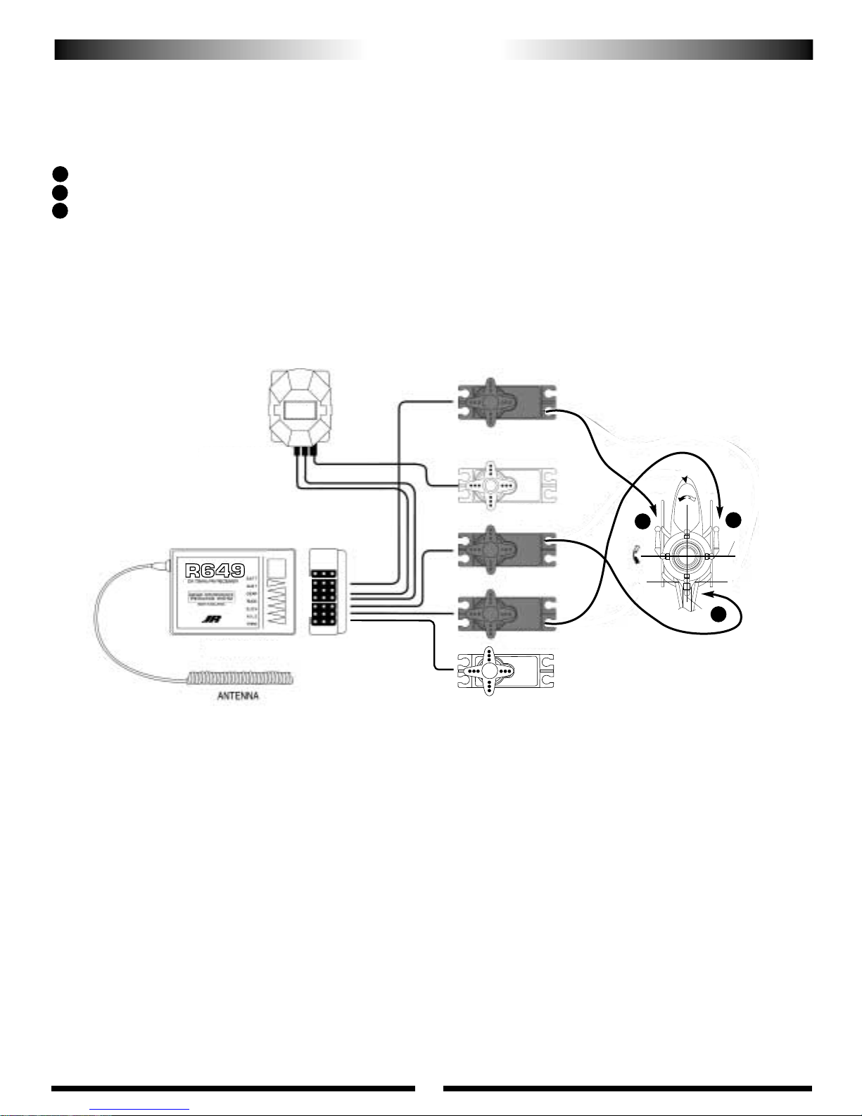
9
45
(Right) (PITCH)
(Right) (RUDDER)
(Right) (THROTTLE)
(Front) (ELEVATOR)
(Left) (AILERON)
The JR®120°/140° CCPM system requires the use of three servos to operate, aileron, elevator, and Aux 1(Pitch). The labeling of
these servos can become quite confusing because with the CCPM function; the three servos no longer work independently, but rather
as a team, and their functions are now combined. For this reason, we will refer to the three servos in the following manner:
Elevator Servo: We will refer to this servo as the “Top” servo. The channel number for this servo when using a JR radio is CH3.
Aileron Servo: We will refer to this servo as the “Right Front” servo. The channel number for this servo when using a JR radio is CH2.
Aux 1 (Pitch) Servo: We will refer to this servo as the “Left Front” servo. The channel number for this servo when using a JR radio is CH6.
Please refer to the CCPM connections chart below for clarification. For non-JR radios, please consult your radio instructions for
proper connection.
C. CCPM SERVO CONNECTIONS
IMPORTANT CCPM PROGRAMMING DOS AND DON’TS (CONTINUED)
G5000T GYRO (OPTIONAL)
(JRPG5000T)
R-649 RECEIVER
G5000T
C
A
B
C
A
B
Page 46
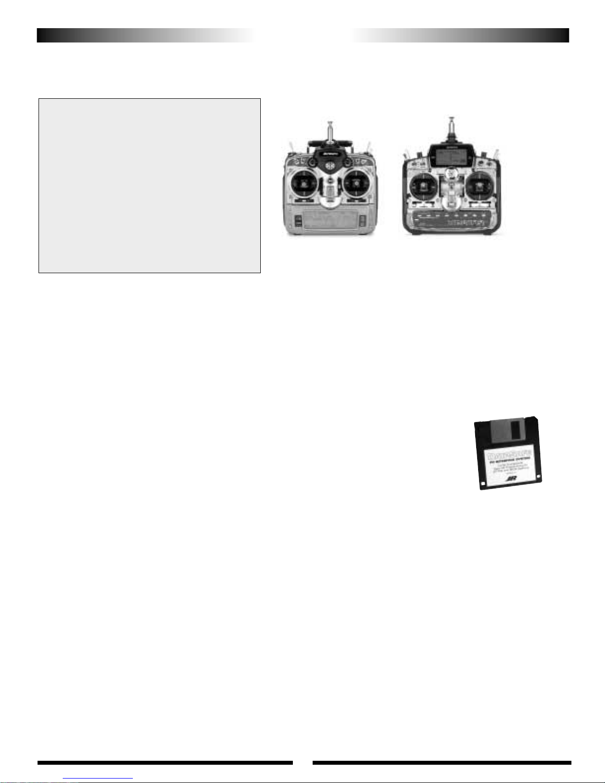
46
CCPM SOFTWARE ACTIVATION AND INITIAL ADJUSTMENT
RADIO SYSTEM REQUIREMENTS (NOT INCLUDED):
6-channel or greater R/C helicopter system with 120° or 140° CCPM function
JR 8103 DIGITAL TRIM AND 10X USERS WITH JR DATASAFE
™
Included with your Vigor™CS kit is a 3.5 disc containing Curtis's refined programming for
the Vigor CS. 8103DT and 10X users can upload this information to their transmitters using the JR
Datasafe system (sold separately). Uploading this information will save a considerable amount of
time programming your transmitter, and will also insure that all data input will be correct. All
programs and data contained on this disc are also listed on the 8103 and 10X data sheets included at
the back of these instructions. Please refer to these data sheets if you have any questions with regards
to the program content during setup. Please refer to the Datasafe instructions for information on
saving this data to your Datasafe, as well as information on how to upload these programs to your
transmitter. It is suggested that the desired program should be uploaded to your transmitter at
this time before proceeding to the next section. Please note that sub trim and stunt trim (digital
trim) values are not included in this program as they will vary from model to model depending on the
servos used. Please refer to Section 7-2 for servo sub trim information. Please note that the
preprogrammed information on the Datasafe disc is set to “SPCM” modulation.
Please note that the programming is designed for use with the following equipment:
Gyro: JR G5000T or G550T Tail Lock Gyros
Servos: JR 8231 or 8411 Digital Servos (Cyclic)
JR 8417 or 8700G Digital/Super Servos (Tail Rotor)
Engine: OS 61 SXH WC
Muffler: YEIMP900 Muscle Pipe Tuned exhaust system
Blades: NHP 700S Symmetrical or 700mm Symmetrical V Blades (Main)
NHP 105mm Tail Rotor Blades (Tail)
If a different combination of equipment is used, it will be necessary to alter the radio
program to match the specific equipment.
Caution: Prior to the first flight, please check to make sure that all control surfaces
move in the correct direction, and that all functions operated correctly.
10X
120° or 140° CCPM
XP8103D.T.
120° CCPM Only
CCPM-Ready JR Radio Systems
Most current JR heli radio systems (XP652, XP8103 w/digital
trims, 10X, as well as older 10 series systems) are equipped
with 120° CCPM electronics for use with JR CCPM
machines. Radios you may be flying now, like the X347,
X388S, XP783, and XP8103*, have 120° CCPM capability
built in but require activiation by the Horizon Service
Department. Please call (217) 355-9511 for details.
*Please note that many XP8103 systems have the CCPM function already
activated. Please check with the Horizon Service Center for details.
Current Radio Systems
JRP1656**PCM 10X, 120° & 140° CCPM
JRP8622**XP8103FM, 120° CCPM
JRP8653**XP8103PCM, 120° CCPM
JRP6622**XP652 FM,120° CCPM
AJR first!
After following complete,
detailed setup instructions, JR
XP8103 & 10X users
can dowload Curtis’s highly
refined programming right into
their transmitters using this
included JR DataSafe disk and
JR’s DataSafe™PC interface .
(DataSafe PC interface set, (JRP A300)
not included)
If you have uploaded Curtis’s program using the JR Datasafe, please proceed to Section 7-1.
Page 47
47
The following activation and setup procedure should be used for all JR 8103 and 8103D.T. systems.
Note: Some early 8103 systems will require the activation of the CCPM software. It’s easy to identify if your system has the
CCPM function activated by identifying if the “SWASH TYP” function appears in the system mode as shown in Section A
below. Please refer to Section A to access the system mode.
Prior to activating the CCPM function, it is first suggested that the data reset function be performed to reset the desired model
number to be used back to the factory default settings.
Caution: Prior to performing the data reset function, it will be necessary to select the desired model number to be used.
A) Model Select/Data Reset
Press the Up and Down keys simultaneously while turning the power switch on to enter the system mode. Next, press the
Up or Down keys to move the cursor to the model select function. Press the Up and Down keys simultaneously to enter
the model select function. Select the desired model number to be used, then press the Clear key to reset the current
model to the factory default settings. Press the Up and Down keys simultaneously to exit the model select function.
B) CCPM Activation
Press the Up or Down keys to move the cursor to the swash type function, then press the Up and Down keys
simultaneously to access the swashplate type function.
Press the Up or Down keys until “3 servo 120°” appears on the screen. Press the Up and Down keys simultaneously two
times to exit the swashplate type function and the system mode.
CCPM SOFTWARE ACTIVATION AND INITIAL ADJUSTMENT (CONTINUED)
2. JR 8103 SYSTEMS: MANUAL PROGRAM INPUT
[SYSTEM M.]
• INFO-DISP
• Model SEL
• MDL Name
• Type SEL
• MDL Reset
• MODULAT
• TRANSFER
• INPUT SEL
• SWASH TYP
[MDL Reset]
MODEL 1
HELI SPCM
[SWASH TYP]
1servo
NORM
[SWASH TYP]
3servos
120
•
3 servos 120°
Page 48

48
C) CCPM Settings
Turn the power switch on, then press the Up and Down keys simultaneously to enter the function mode. Press the Up key
until “Swash Mix” appears on the screen. Once this has been completed, it will be necessary to change the value of the
aileron, elevator, and pitch functions from the factory default setting using the + and - keys.
D) Servo Reversing
Press the Up key until “Rev. Sw.” (Servo Reversing) appears on the screen. Next, reverse channels 3, 4, and 6 by moving the
cursor with the Channel key, then pressing the + or - keys.
E) Travel Adjustment
Press the Up key until “TRVL. ADJ.” (travel adjust) appears on the screen. Adjust the values as shown using the channel key
to move the cursor, and the + and - keys to set the value. Press the Sel key to access the pitch channel values and set as
indicated. Please note that the required travel values will vary based on the type of servo selected.
Note: The travel values shown for the rudder function are for use with Piezo type gyros, like the JR G550T or G5000T type gyros.
CCPM SOFTWARE ACTIVATION AND INITIAL ADJUSTMENT (CONTINUED)
PIT.
£H 100%
L 100%
AUX3
+ 100%
- 100%
[TRVL ADJ.]
£THRO
H 150%
L 150%
AILE
£L 100%
R 100%
ELEV
D 100%
U 100%
RUDD
£L 70%
R 70%
[SWASH MIX]
3servos
120
•
EXP ACT
AILE +48%
ELEV +52%
∞ PIT. +60%
PIT.
£H 115%
L 115%
AUX3
+ 150%
- 150%
[TRVL ADJ.]
£THRO
H 150%
L 150%
AILE
£L 115%
R 115%
ELEV
D 115%
U 115%
RUDD
£L 150%
R 150%
Digital Servos/Super Servos
Standard Servos
[REV.SW]
1
2345678
ch
REV.
NORM.
REV NORM
THR
AIL
ELE
RUD
GER
PIT
AUX1
AUX2
Page 49

49
The following activation and setup procedure should be used for all JR PCM10, 10S, 10SX, 10SxII, and 10X systems.
Prior to activating the CCPM function, it is first suggested that a data reset function be performed to reset the desired model
number to be used back to the factory default settings.
Caution: Prior to performing the data reset function, it will be necessary to select the desired model number to be used. Access the
model select function (code 84) and select the desired model to be used.
A) Data Reset
Access the data reset function (code 28) once the correct model number
has been established. Next, press the Clear key to reset the current model.
Press the Enter key to exit the data reset function.
B) CCPM Activation
Access the swash type function (code 65). Next, press the SEL key until
“3 servos (120°)” appears on the screen. For 10X owners, press the SEL key
until “3 servos (140°)” appears on the screen. 140 CCPM is only found in the
JR 10X radio system and was specifically designed for use with the Vigor CS.
Once this is complete, it will be necessary to change the value of the aileron,
elevator, and pitch function from the factory default settings using the
+ and - keys below the pitch value. Press Enter to exit the swash type function.
C) Servo Reversing
Access the servo reversing function (code 11). Next, reverse channels 1, 2, and
4 by pressing the desired channel number. The screen should appear as shown.
Press Enter to exit the servo reversing function.
D) Travel Adjust
Access the travel adjust function (code 12) and adjust the servo travel values as shown. Please note that the required travel
values will vary based on the type of servo selected. Press Enter to exit the travel adjust function.
Note: The travel values shown for the rudder function are for use with Piezo type gyros, like the JR G550T, or G5000T
type gyros. If a conventional mechanical type gyro is used (JR 120, 130 etc.), then the travel value of the rudder channel
will need to be reduced to approximately 100%.
CCPM SOFTWARE ACTIVATION AND INITIAL ADJUSTMENT (CONTINUED)
3. JR 10 SERIES SYSTEMS: MANUAL PROGRAM INPUT
SETUP PROCEDURE
[DATA RESET]
MODEL 1 SPCM
CLEAR ENTER
[SWASH TYPE]
3SERVOS(120•)
FXP AILE ELEV PITCH
[NH +48% +52% +60%
ENTER
SEL ACT + –CL+ –CL+ –
CL
[REVERSE SW]
REVERSE
NORMAL
ENTER
1 2 3 4 5 6 7 8 9 10
[TRAVEL ADJUST]
THRO AILE ELEV RUDD
H110% L115% D115% L150%
L110% R115% U115% R150%
PAGE
+ –CL+ –CL+ –CL+ –
CL
[TRAVELADJUST]
PITCH
+115%
-115%
+ –CL+ –
CL
[TRAVEL ADJUST]
THRO AILE ELEV RUDD
H100% L100% D100% L150%
L100% R100% U100% R150%
PAGE
+ –CL+ –CL+ –CL+ –
CL
[TRAVEL ADJUST]
PITCH
+100%
-100%
+ –CL+ –CL+ –
CL
[CLEAR]
Select 3 Servos(120°)
digital servos/super servos
Standard servos
Page 50

50
7-1
PREPARATION AND INSTALLATION OF SERVO HORNS
............. 6 pcs
................. 6 pcs
..................... 6 pcs
Flat Head Screw, 2 x 8 mm
Steel Joint Ball
Hex Nut, 2 mm
Cut*
See note
JR Large
HD Servo Horn
27 mm
Front side
of horn
Back side of horn
Flat Head Screw
2 x 8 mm(6 pcs)
Steel Joint Ball (6 pcs)
Hex Nut, 2 mm (6 pcs)
Test fit the servo horns to achieve the correct position as shown.
Servo horn positions can be fine tuned using sub trim. Please refer to Section 7-2.
Red
Use Red
Threadlock
JR HD Servo Wheels or equivalent will be required for this step (JRPA216, not included)
Before trimming the servo horns as shown, it is first suggested that these horns be test fit to the servo to achieve the
correct positioning. JR servos utilize a 21 spline output shaft, which allows the position of the servo arm to be varied
when rotated at 180-degree intervals.
To test fit the servo horns, turn the radio system on, and set the collective stick to the center position.
Next, test fit the servo arms at 180-degree intervals to find the direction that will allow the horn to be positioned as close
to the vertical position (90 degrees from the servo case) as possible as shown in the diagram. This will reduce the amount
of sub trim needed to bring the servo horns to the exact 90-degree position as shown.
Once the position for each horn has been established, mark the servo arms for trimming, while also noting the servo
that they have been fitted to (A, B, or C).
Trim the servo horns as shown and attach the steel control balls in the desired hole locations.
Reattach the servo horns to the servos, remembering to secure the horns to the servos using the servo horn screw. Final
sub trimming of the servos will be performed in the proceeding Section 7-2.
Note:
Page 51
51
1. XP8103 SYSTEMS
1) With the radio power switch on, press the Up and Down keys simultaneously to enter the function mode.
2) Press the Up key until “Sub Trim” appears on the screen.
3) Adjust the left (aileron), right (Aux 1), and top (elevator) servos as needed until the servo arm is exactly
parallel to the servo as shown when the collective stick is in the center position. It will be necessary to press
the SEL key once to access the right servo (Aux 1) sub-trim.
4) Press the Up and Down keys simultaneously to exit the function mode.
[Sub Trim]
£THRO ∞AILE
00
ELEV RUDD
00
[Sub Trim]
£GEAR ∞ PIT.
00
AUX2 AUX3
00
Increase or decrease
the value to center the
front servo.
Increase or decrease
the value to center the
right servo.
Increase or decrease
the value to center the
left servo.
SEL
2. JR PCM10, 10S, 10SX, 10SXII, 10X SYSTEMS
1) Enter the sub-trim function (code 15).
2) Adjust the left (aileron), right (Aux 1) and top (elevator) servos as needed until the servo arm is exactly
parallel to the servo as shown when the collective stick is in the center position. It will be necessary to press
the Page button to access the right servo (Aux 1) sub-trim value.
3) Press Enter to exit the sub-trim function.
[SUB TRIM]
THRO AILE ELEV RUDD GEAR
00000
ENTERPAGE
+ –CL+ –CL+ –CL+ –CL+ –
CL
Press Page to
access the second
screen.
Increase or decrease
the value to center the
left servo.
Increase or decrease
the value to center the
front servo.
[SUB TRIM]
PIT. AUX2 AUX3 AUX4 AUX5
00000
ENTERPAGE
+ –CL+ –CL+ –CL+ –CL+ –
CL
Increase or decrease the value to
center the right servo.
It may be necessary to make minor servo centering adjustments with the use of the sub-trim function to
achieve the desired servo arm positions. Please refer to your particular radio’s section as listed below or consult
your radio instruction manual for more information.
7-2
CCPM SERVO CENTERING WITH THE SUB-TRIM FUNCTION
Page 52
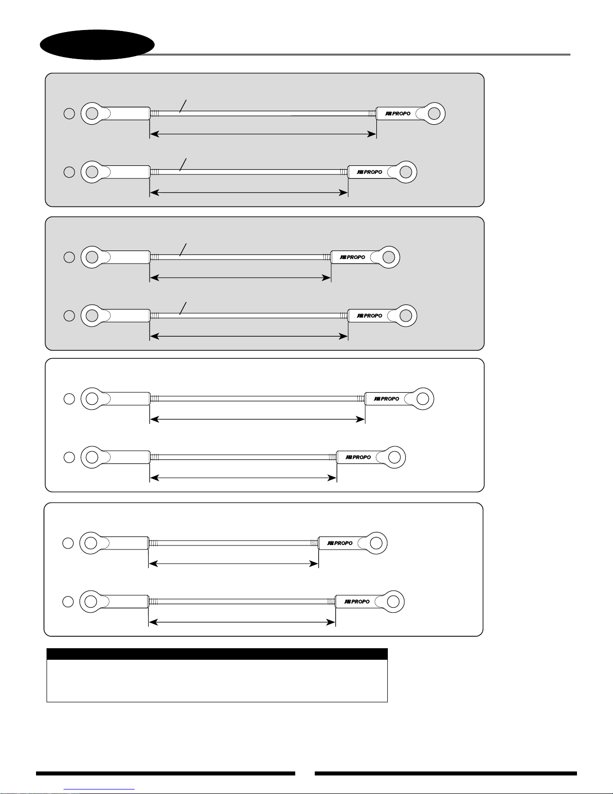
52
7-3
120Standard Range (For 8103 and 10 Series Systems)
A
B
140Standard Range (For 10X Systems only)
A
B
CONTROL ROD ASSEMBLY
Control Rod, 2.3 x 95 mm
64.5 mm
Control Rod, 2.3 x 85 mm
70.5 mm
Control Rod, 2.3 x 80 mm
64.5 mm
Control Rod, 2.3 x 85 mm
70.5 mm
.........4 pcs
.........2 pcs
.........4 pcs
.........2 pcs
120Wide Range
A
B
140Wide Range
A
B
Control Rod, 2.3 x 95 mm
.........4 pcs
76 mm
Control Rod, 2.3 x 85 mm
.........2 pcs
66 mm
Control Rod, 2.3 x 80 mm
.........4 pcs
60 mm
Control Rod, 2.3 x 85 mm
.........2 pcs
66 mm
Note:
All instructions are based on the use of the "standard range" CCPM setup.
It is not recommended that the "wide range" setup be used.
Page 53
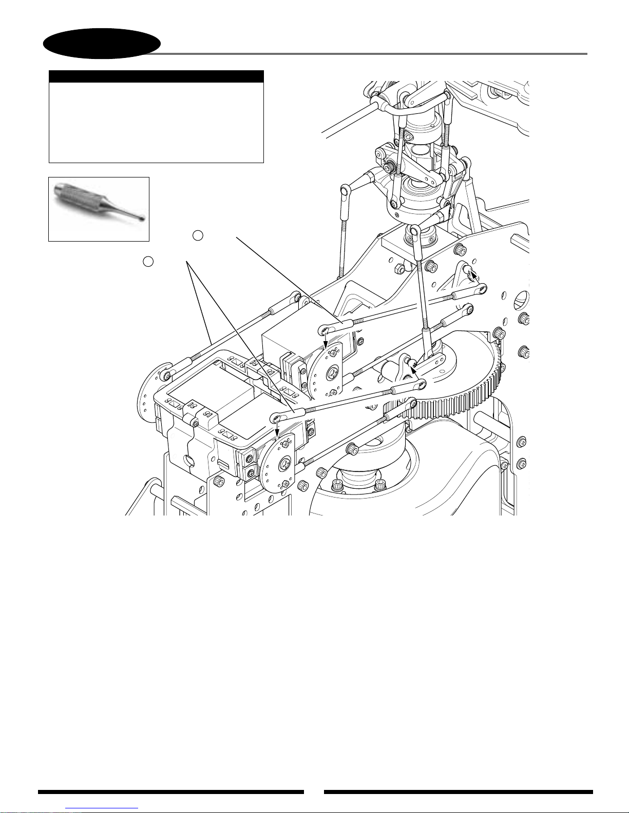
53
7-4
Use JR Ball Link
Sizing T ool
Attach the control rods to the servo arms first.
Next, test fit the rods to the T-lever balls to
ensure that the rods are the correct length.
If the rods are too long or too short, adjust
each rod an equal amount until the control
rods line up with each of the T-lever control.
Rod A (4 pcs)
CCPM CONTROL ROD ATTACHMENT
Note:
Rod B (2 pcs)
Page 54
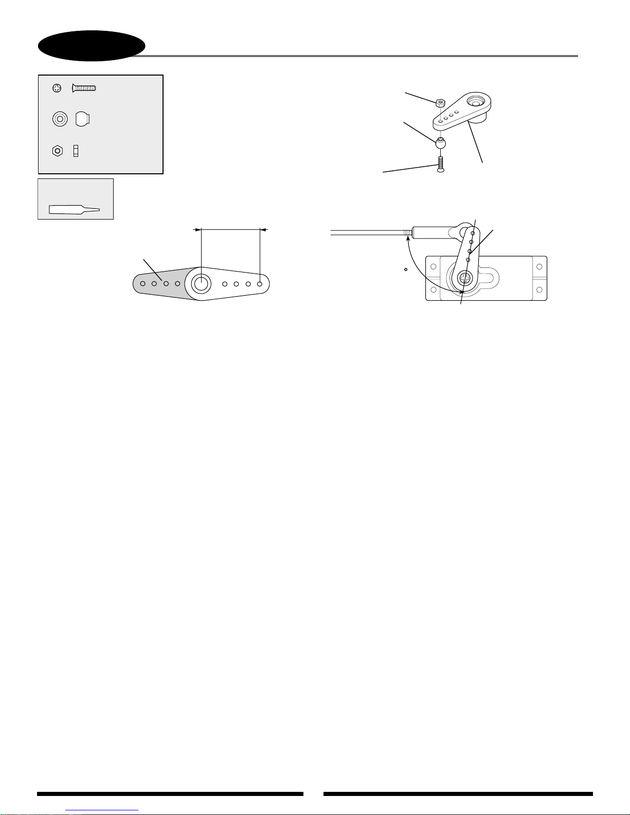
54
7-5
TAIL CONTROL ROD CONNECTION
..............1 pc
Flat Head Screw, 2 x 8 mm
.................1 pc
Steel Joint Ball
.....................1 pc
Hex Nut, 2 mm
Use Red
Threadlock
Remove shaded area.
Adjust the length of the tail
control rod until the tail
pitch slider is in the center
of its travel and the servo
arm is at the position shown
below (offset).
18 mm
Hex Nut, 2 mm
Steel Joint Ball
Flat Head Screw,
2 x 8 mm
90
Note that control
ball is attached
to the inside
of the servo arm.
Servo Horn
Servo arm should
be offset 1–2 servo
splines at neutral.
Offsetting the servo arm as shown
will "balance" the feel of the tail
rotor during flight.
Page 55
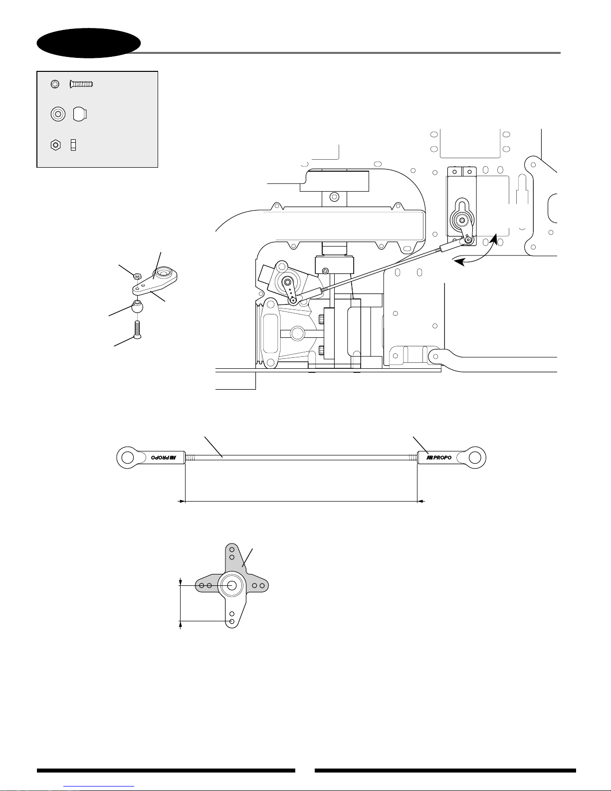
55
7-6
High
Throttle
Low
Throttle
THROTTLE LINKAGE CONNECTION
..............1 pc
Flat Head Screw, 2 x 8 mm
.................1 pc
Steel Joint Ball
....................1 pc
Hex Nut, 2 mm
Servo Horn
Hex Nut, 2 mm
Steel Joint Ball
Flat Head Screw,
2 x 8 mm
*Option: For smooth operation,
pre-size the ball links with the
JR ball link sizing tool prior to
attachment.
Attach the
joint ball to
the outside
of the servo
arm.
12.5 mm
JR
Universal Link (2 pcs)Control Rod, 2.3 x 100 mm
82 mm (approximate)
Remove
shaded area.
Page 56
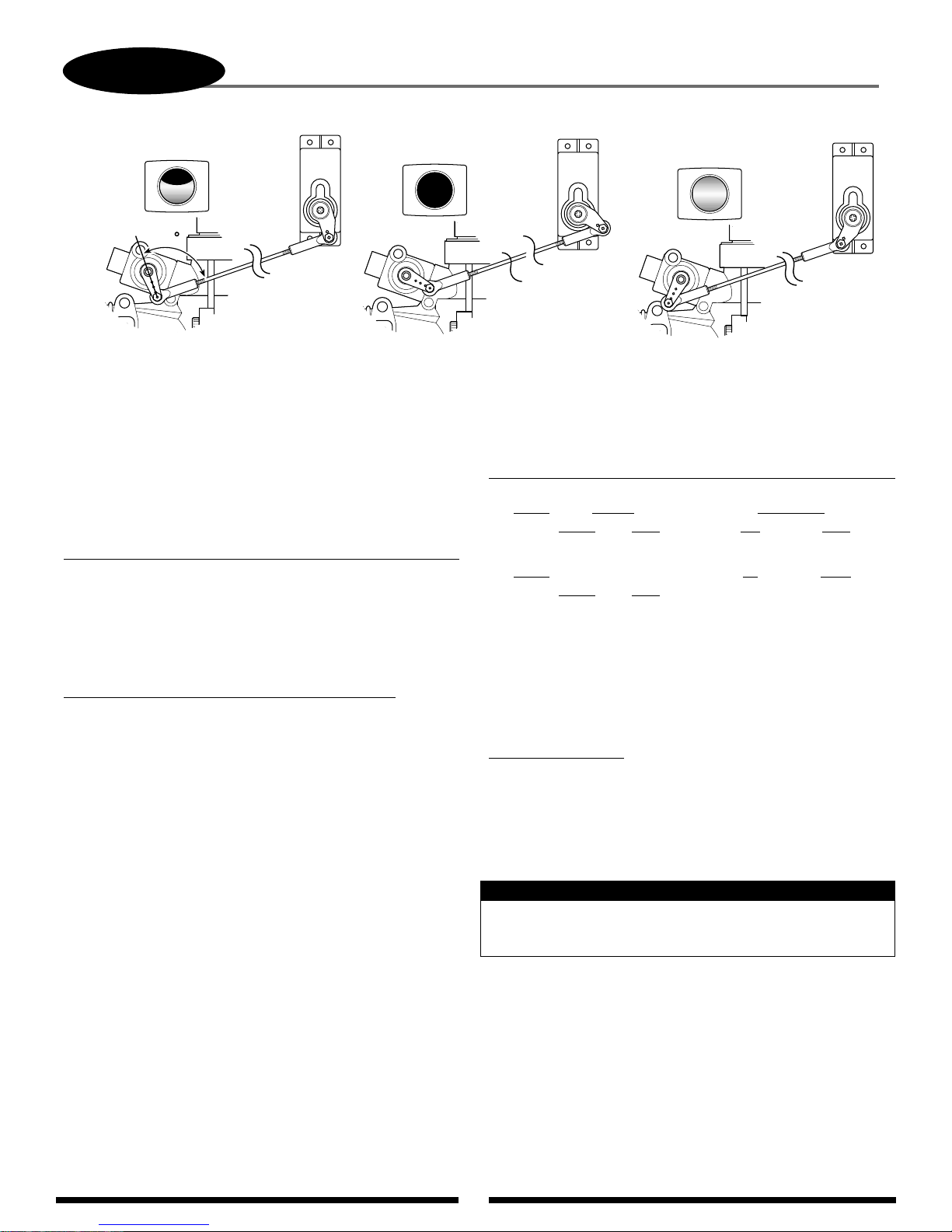
56
7-6.1
To achieve the correct position of the throttle/servo arm, it may be necessary
to re-position the throttle arm on the carburetor. It may also be necessary to
adjust the length of the throttle linkage slightly to achieve full open and
closed positions of the carburetor.
Throttle Travel Adjustment (Initial Setup Only) 10 Series & Other Systems
It is also possible to increase/reduce the travel of the throttle servo through
the travel adjust function found in most computer radio systems. If this
function is used, make sure the values for the high and low positions remain
equal (same value for high/low). If these values are not equal, it will create
a differential, or uneven movement of the throttle, making rotor rpm
adjustment and fine tuning more difficult.
Throttle Travel Adjustment (Full 3D Setup) with 8103 Systems
When setting up your throttle linkage for cyclic to throttle mixing with
many radio systems, it will be necessary to make any adjustment in the
throttle travel limits by mechanical means only. Move the control linkage in
or out on the servo/throttle arms until the correct barrel travel is achieved.
Please note that it is very important the ATV (travel volume) for both the
high and low throttle setting remain at their maximum values (150%) to
prevent over-travel and binding of the throttle linkage when cyclic to throttle
mixing is used.
For initial cyclic to throttle mixing value information, please refer to the JR
8103 and PCM10X series data sheets located on pages 73-77 of this manual.
Please note that the values and mixing channels shown are universal to most
radio systems currently available.
Cyclic to Throttle Channel and Mixing Values (most systems)
*Numbers shown correspond with the correct JR channel numbers
Mixing Value Adjustment
Please note that it will be necessary to determine if the desired mixing
values need to be a + or - value based on servo direction, etc.
To verify the proper direction, move the control surface in each direction
while watching the throttle arm. Throttle should increase each time a control
surface input is given. Adjust the + or - value as necessary until the proper
mix is achieved.
Also check to confirm that the throttle travel is correct and is not causing a
bind in the control linkage after the cyclic mixing has been added.
*To avoid differential throttle travel, make certain both the throttle arm and the servo horn are positioned as shown in the above diagrams.
Mixing V
alue
Left
Right
20 20
Up
Down
20 20
Mix #1 Channel
Master
Slave
Aileron(2)* Throttle (1)*
Mix #2
Master
Slave
Elevator(3)* Throttle (1)*
Note:
90
THROTTLE ARM/SERVO HORN POSITIONS
1/2 Stick (Throttle) Position
(Throttle Barrel 1/2 open)
High Stick (Throttle) Position
(Throttle Barrel Fully Open)
Low Stick (Throttle) Position
(Throttle Barrel Fully Closed)
Page 57
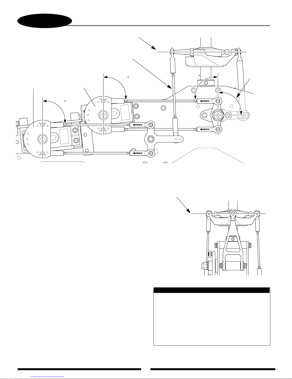
57
7-7
Adjust the control rods as needed until the swashplate
is level with all servos in their neutral (90°) position.
Left Servo (C)
90
CHECKING THE SWASHPLATE FOR LEVEL
Check to insure the
swashplate is level on
the fore-aft axis.
90
Top Servo (A)
90
Reconfirm
that the
elevator
arm is at 90°.
90
After the control linkages have been attached to the
swashplate, it will be necessary to check the swashplate to
insure that it is level. To do this, turn on the radio system and
place the collective stick in the center position as before. Next,
check to make sure that all trim levers and knobs are also in
their center position.
Check to insure that the servo arms are parallel to the
servos as adjusted in the previous step. If the servos are not
parallel, please refer to the sub-trim section 7-2 and readjust
as necessary.
Once it’s determined that the servo arms are parallel to
the servos as required, it will now be necessary to check the
swashplate to insure that it is also level or neutral in this
position. It is suggested that the swashplate first be checked
from the rear of the model to insure that it’s level from left to
right. If the swashplate is not level as compared to the frame of
the model, adjust either the left or right servo control rods as
needed. To determine which rod needs adjustment, it may be
helpful to view the swashplate from the left and right side view
of the model to determine which side is high or low.
Once this left to right adjustment is completed, it will
now be necessary to check the fore/aft position of the swashplate
to insure that it is also level on this axis. If the swashplate is not
level in the fore/aft axis, it is suggested that the adjustment be
made to the front servo control linkage as needed by slightly
repositioning the elevator control arm on the elevator a-arm
assembly, or adjusting both front servo control rods.
If you are unsure as to which linkage needs adjustment
or are having difficulty obtaining the correct adjustment, please
check the length of each control rod to insure that it is adjusted
to the correct length as outlined in Step 5-3.
Check to insure that the
swashplate is level on the left/right axis.
Note:
If care was taken in the linkage assembly in Steps 4-6 and
7-3, little or no adjustment should be required in this step.
Only minor adjustments should be made to the lengths of
the control linkages at this time. Any major adjustments
indicates either incorrect linkage lengths or incorrect
servo arm positioning. If the control linkage lengths are
altered from the recommended lengths more that one or
two turns, this will have a great effect on the range and
settings of the collective pitch in later steps.
Page 58
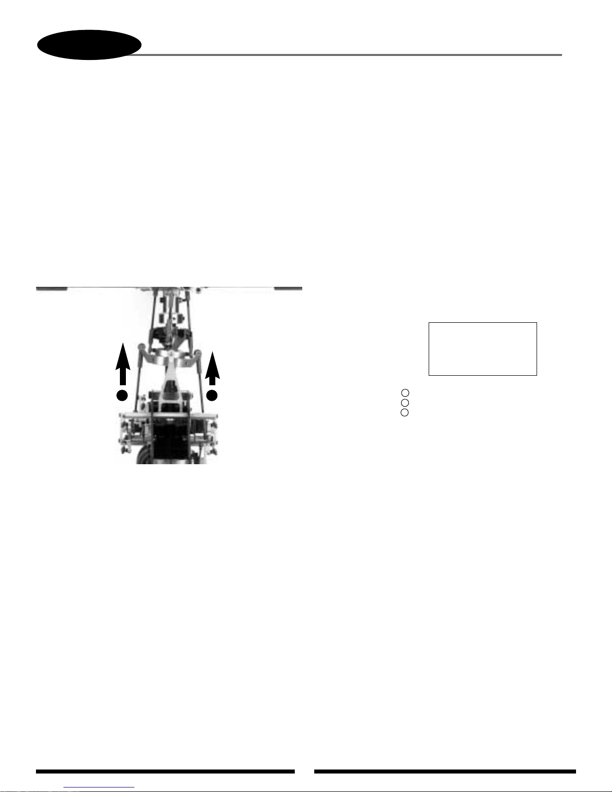
58
It is very possible that the travel of each servo varies slightly, which can cause the swashplate to be tilted to
the left or right when the collective is moved to the extreme high and low pitch positions. This condition is
generally more common when standard type servos are used. If JR®digital servos are used, the adjustment
required is generally very small, if any. These variations in travel can be corrected by altering the travel value
of each servo slightly through the travel adjustment function.
To check the pitch-to-aileron mixing, it will first be necessary to position the collective stick in the center
position as in the previous steps. Next, move the collective stick from the center position to the high pitch
position while viewing the swashplate from the rear of the model as shown in the diagram below. While
moving the swashplate, look for any tendency for the swashplate to roll to the left or right as it reaches the high
pitch position. Repeat this procedure several times to be sure that your observations are correct. If no rolling
tendency is found, it will now be necessary to repeat this procedure from the center collective stick position to
full low pitch. If no rolling tendency is found, proceed to Step 7-9.
In our example, we have shown that the swashplate has been tilted to the right as the collective has been
increased to full pitch. This would indicate that the left servo’s maximum travel is greater than the right servo’s
maximum travel.
In this condition, we suggest that the travel value for the left servo be reduced slightly (5–10%). Repeat
the procedure above if the same condition occurs, but to a lesser degree. The travel value of the right servo
should be increased slightly and retested. In most cases, it will require only the adjustment of the left or right
servo to correct this situation.
View is shown from the rear of the model. Notice how the
swashplate has tilted to the right as the collective has moved
from center to full high pitch position.
High
Low
Once this condition has been
corrected, repeat this procedure for
the center to low collective pitch
position and adjust as needed.
ELEV= Top Servo
AUX1= Right Front Servo
AILE= Left Front Servo
7-8
A
B
C
C B
PITCH-TO-AILERON MIXING ADJUSTMENT WITH TRAVEL ADJUST
Page 59
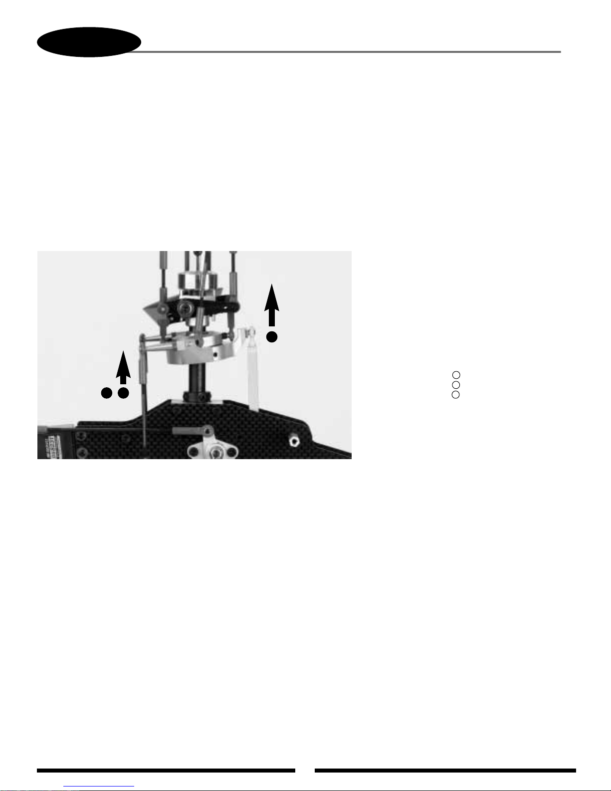
59
7-9
The total travel of each servo can vary slightly, which can also cause the swashplate to be tilted fore and aft
when the collective is moved to the extreme high and low pitch positions. This situation can also be corrected if
necessary through the use of the travel adjustment function.
To check pitch-to-elevator mixing, it will first be necessary to position the collective stick in the center position
as in the previous steps. Next, move the collective stick from the center to the high pitch position while viewing the
swashplate from the left side of the model. While moving the swashplate, look for any tendencies for the swashplate
to tilt fore or aft as it reaches the high pitch positions. Repeat this procedure several times to be sure that your
observations are correct. If no fore or aft tilting tendencies are found, it will now be necessary to repeat this
procedure from the center collective stick position to full low pitch. If no tilting tendency is found, proceed to the
next step.
In our example, we have shown that the swashplate has tilted forward as the collective has been increased to full
high pitch. This would indicate that the top servo’s maximum travel is more than that of the two left/right servos.
In this condition, we suggest that the travel value for the top servo be decreased slightly (5–10%). Repeat the
above procedure and decrease the value as needed until the tilting tendency is eliminated. For information on the
travel adjustment function, please refer to your radio’s instruction manual for details. Once this condition has been
corrected, repeat this procedure for the center to low collective pitch position and adjust as needed.
Note: It is very important that during this step, only the travel value for the top servo (elevator) be adjusted to
correct any pitch-to-elevator tendencies. If the travel value of the left or right servo changes, this will
affect the pitch-to-aileron tendencies corrected in the previous step. If you feel that readjustment of the
left and right servo travel is necessary, then it is suggested that the travel for each servo be increased or
decreased at the same amount and the pitch-to-aileron procedure be retested.
View is shown from the left side of the
model. Notice how the swashplate has
tilted forward as the collective has
moved from the center to the full high
pitch position.
High
Low
ELEV= Top Servo
AUX1= Right Front Servo
AILE= Left Front Servo
A
B
C
CB
A
PITCH-TO-ELEVATOR MIXING ADJUSTMENT WITH TRAVEL ADJUST
Page 60

Now that the radio system is completely installed into the helicopter, it’s
necessary to check and adjust the following:
1. Servo Direction (Servo Reversing)
Check to insure that all servos have been set to the correct direction as
shown in the Control Linkage Installation section.
2. Dual Rates
It’s suggested that for initial flights, the dual rate function values be
set as follows:
0 Position (low rate) 90%
1 Position (high rate) 100%
3. Exponential Settings
It’s suggested that the exponential rate settings remain in the 0 value
position until the initial test flights. After initial flights, adjust the
exponential values to achieve the desired control feel.
4. Sub-Trim Settings
It’s suggested that the correct neutral settings be achieved without the
use of the Sub-Trim function, as this will affect the neutral position of the
servos. Adjust the cyclic trim using the control rods until a neutral hover
is achieved.
5. Pitch/Throttle Curve Adjustment
It is very important the throttle and pitch curves are adjusted properly to
achieve the best performance from your helicopter. When properly adjusted,
the main rotor head rpm should remain consistent throughout all
maneuvers and throttle stick positions. Aconstant rpm will also help to
improve the effectiveness and accuracy of the tail rotor and gyro systems.
A) Pitch Curve
It will now be necessary to establish the maximum pitch
value required for your application prior to adjustment. For
example, if you are a 3D pilot, then your maximum negative
pitch will be -10, and your maximum positive pitch will be +11.
The maximum pitch range that you will require will be 21° total.
The maximum pitch range mentioned above must be
established through the use of the pitch travel value in the CCPM
function. As mentioned previously, do not try to establish the
maximum pitch curve values through adjustment of the travel
adjustment function, as this will alter the pitch-to-aileron and
pitch-to-elevator travel values established in Steps 7-8 and 7-9.
Please refer to the CCPM activation section (page 46) for
information on how to access the CCPM function.
Once the CCPM function has been activated, set the
maximum positive pitch settings as mentioned above. Since the
CCPM function does not allow for independent travel settings for
positive and negative pitch, it will be necessary to establish the
maximum positive pitch, since this is generally the largest degree
of pitch in the pitch range. Once the maximum positive pitch
range is set, the maximum negative pitch range can be reduced as
needed through the pitch curve function.
Set the main rotor pitch gauge to the desired maximum pitch
setting, then increase or decrease the CCPM pitch travel (labeled
Pitch or Ch6) as needed until this pitch setting is achieved.
Once this procedure has been completed, the positive and
negative pitch settings for each flight mode can be adjusted
through the radio’s pitch curve function. Please refer to your
radio’s instruction manual for more information.
60
FINAL SERVO ADJUSTMENT AND RADIO SETUP
0°
-9°
1°
Normal
(Hover)
Stick Position
Low 1/4 1/2 3/4 High
Stick Position
Stick Position
Flight Mode 1
3D Stunt 1
Autorotation
(Throttle Hold)
Flight Mode 2
3D Stunt 2
(Duplicate of #1)
Pitch Curve Settings
Pitch Range
+11.5°
0°
-9°-9°
Low 1/4 1/2 3/4 High
Pitch Range
+11°
0°
-9°
Low 1/4 1/2 3/4 High
Pitch Range
+11.5°
-9°
1°
2°
4°
3°
2°
3°
4°
Flight Application Low Pitch Hovering Pitch High Pitch
Mode (Low Stick) (Half Stick) (High Stick)
N Hovering -9° +5° +10°
I 3D Flight #1 -9° +5° +11°
*2 3D Flight #2 -9° +5° +11°
H Autorotation -9° +5° +11.5°
Pitch Range Settings
[SWASH
TYPE]
3SERVOS(120•)
EXP AILE ELEV PITCH
+48 +52 +60
ENTER
SEL ACT + –CL+ –CL+ –
CL
Increase or decrease
the value as needed.
Increase or decrease
the value as needed.
[SWASH MIX]
3servos
120
•
XP8103 System
PCM 10 Series
AILE +48%
ELEV +52%
∞ PIT. +60%
Note: Flight modes #1 and #2 are duplicated for safety.
Stick Position
0°
-9°-9°
Low 1/4 1/2 3/4 High
Pitch Range
+11°
1°
2°
4°
3°
1
Page 61
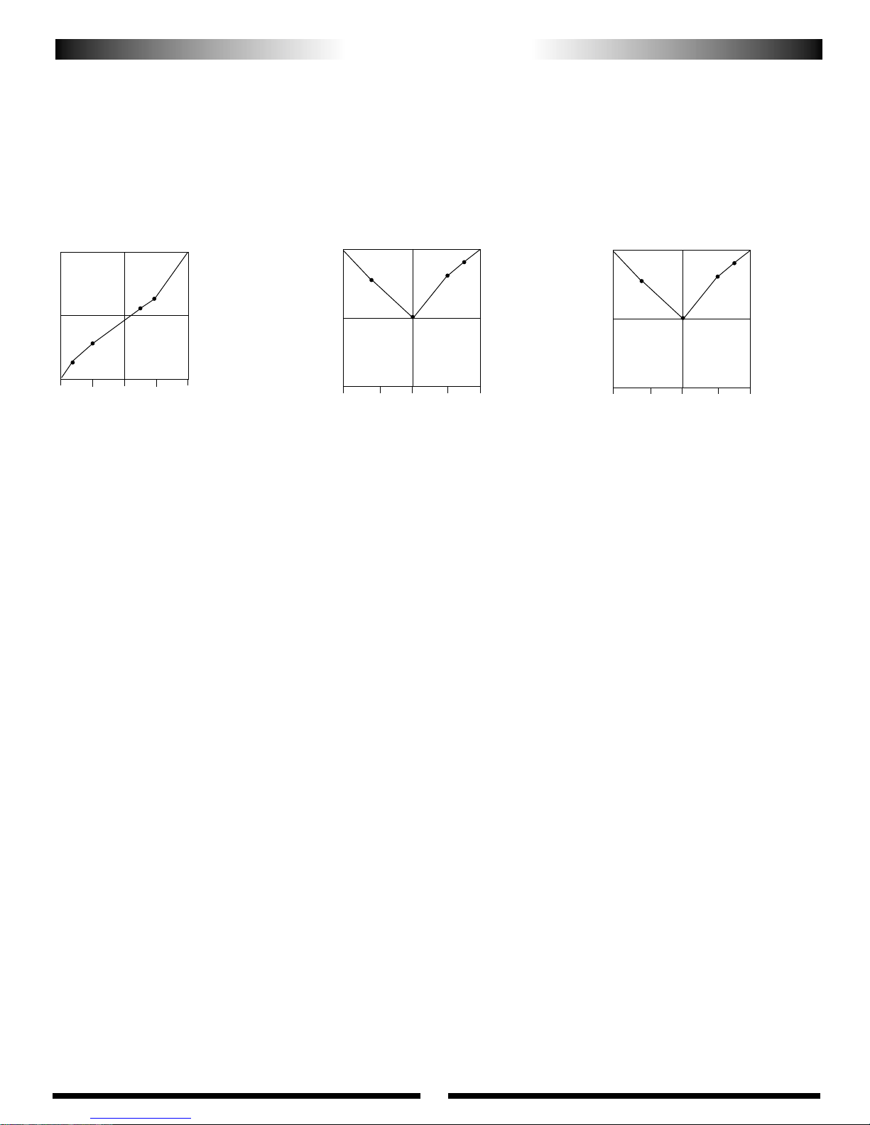
61
FINAL SERVO ADJUSTMENT AND RADIO SETUP (CONTINUED)
It will also be necessary to set the correct idle speed of the engine when the
throttle hold function is activated.
This idle value is located within the throttle hold function. This will allow the
engine to remain at idle when practicing autorotations.
6. Revolution Mixing (Non-Tail Lock/Heading Lock Gyros)
It will be necessary to adjust the revolution mixing to properly
compensate for the torque of the engine during all flight conditions
(except autorotation) if an on tail lock/heading lock gyros is used.
Since there are many variables that can alter the value of the
revolution mixing (engine, blade pitch, fuel, etc.), it will be necessary
to fine tune this function during test flights.
The following values are shown only as a starting point toward achieving
proper compensation:
Flight Mode N Flight Mode 1 Flight Mode 2 (3D)
Up 40 Up 15 Up 15
Down 20 Down 10 Down 15
7. Gyro Gain Adjustment (All Gyros)
It will be necessary to adjust the “gain” or compensation of the gyro to
create the correct amount of “holding power” necessary for a solid
neutral tail rotor. The intent of the gyro is to compensate for abrupt movements,
or wind direction changes, working in conjunction with the Revolution Mixing
Function (non-heading lock gyros).
For hovering, it’s recommended that you start with the gyro gain at
approximately 80° and continue to increase slightly until the tail of the
helicopter “hunts,” then reduce the value slightly.
This same adjustment will also be necessary to achieve proper forward flight.
Generally, the gyro gain for forward flight will be approximately 10% – 20% less
than that of the established hover gain due to aerodynamic forces present in
forward flight. This variance depends greatly on the specific gyro used.
If you are using a dual rate gyro, adjust the gain so you are using the “higher”
gain setting for hover and the “lower” gain setting for forward flight.
Gyro Direction
It will also be necessary to confirm the direction the gyro compensates when the
body of the helicopter is rotated.
To do this, turn the radio system on and suspend the helicopter by the main rotor
head. Next, move the rudder stick to the right and watch the direction that the tail
rotor servo arm travels. Now while watching the tail rotor servo arm, rotate the
body of the helicopter counterclockwise. The servo arm should move in the same
direction as when the rudder stick was moved to the left.
If the arm moves in the opposite direction, reverse the gyro and re-test.
Note: The throttle curve examples shown correspond to
the pitch curve examples show in Step 5 on the
previous page.
40%
Hovering
100%
50%
0% Idle
Power Output
3D Flight Stunt 1
Stick PositionStick Position
Output
Flight Mode 1
B) Throttle Curve Settings
Below are several examples of possible throttle curves during various
flight conditions.
Since throttle curves can vary greatly due to engine and muffler
combinations, it will be necessary to fine tune and adjust these values
during test flights to achieve a constant main rotor rpm.
50°
40°
60°
0% Idle
Power Output
100%
+10°
Flight Mode
N
L: 0
1: 29
2: 38
3: 50
4: 56
H: 100
Output
L: 100
1: 84
2: 60
3: 86
4: 94
H: 100
Low
1/4
1/2
3/4
High
Low 1/4 1/2 3/4 High
40%
100%
50%
0% Idle
Power Output
3D Flight Stunt 2
(Duplicate of #1)
Stick Position
Flight Mode 2
Output
L: 100
1: 84
2: 60
3: 86
4: 94
H: 100
Low 1/4 1/2 3/4 High
Normal Mode
1
2
3
4
1
2
3
4
1
2
3
4
Page 62
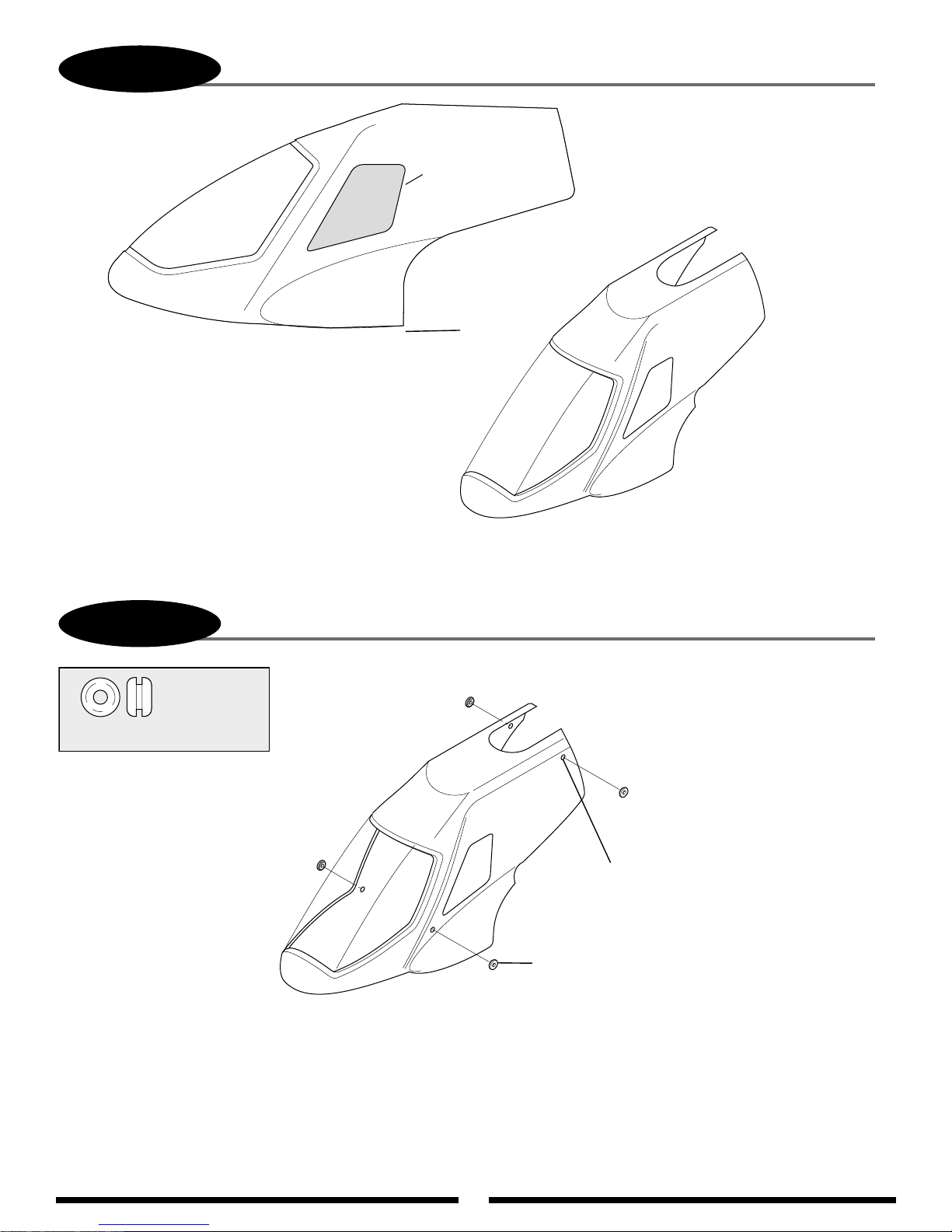
62
8-1
*It may be necessary to trim the lower edge of
the canopy slightly if it contacts the lower tank
mounts.
TRIMMING OF BODY ASSEMBLY
Cut here
(remove)
*
Trim
8-2
.........4 (or 6) pcs
Rubber Grommets
GROMMET ATTACHMENT
Drill four 15/64" holes
and insert rubber
grommets as shown.
Rubber Grommets (4 pcs)
Page 63
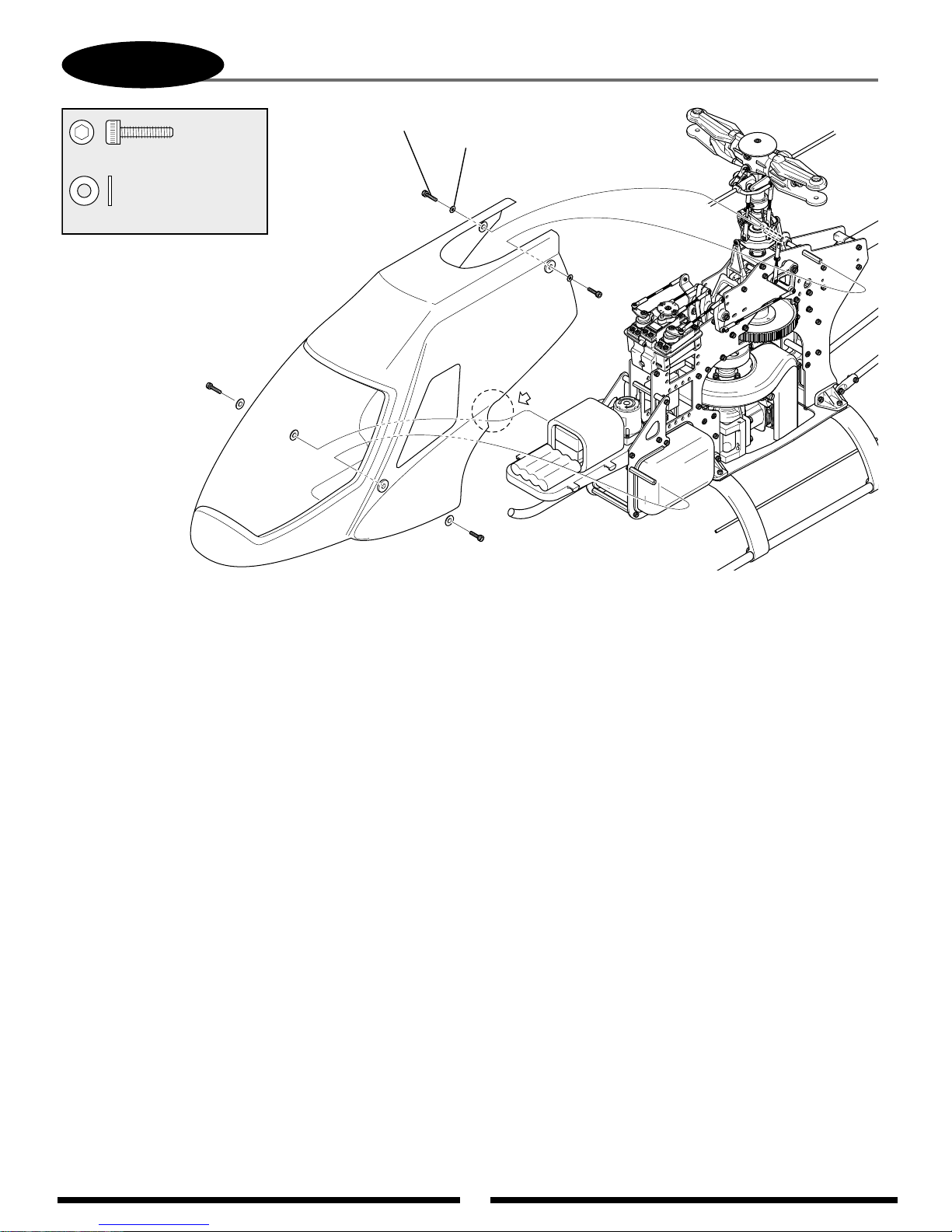
63
8-3
BODY ATTACHMENT & FINAL FITTING
...2 (or 6) pcs
Socket Head Bolt 3 x 12 mm
...................2 (or 6) pcs
Flat Washer, 3 mm
Socket Head Bolt, 3 x 12 mm (2 pcs)
Flat Washer, 3 mm (2 pcs)
Check to insure the body does not come in contact with any portion of the main frame, muffler, servo, servo horns, etc. Trim for
clearance if necessary. Trim and remove a small portion of the canopy shown in the circle above as it is very close to the
cooling fan shroud (left side only).
CANOPY PREPARATION AND PAINTING
Before sanding or painting the canopy, it is first suggested that the canopy be cleaned using Lacquer thinner, or rubbing
alcohol to remove any mold release agent that may still be present on the canopy.
Lightly sand the entire canopy using 180 to 220 grit sandpaper or "Scotchbrite" sanding material so that all areas of the
canopy have a dull appearance.
Clean the canopy again using rubbing alcohol to remove all sanding dust.
Apply a coating of primer to the canopy. Many modelers use a lacquer based automotive primer available in most automotive
supply stores.
Once the primer dries, check the canopy for any pinholes that may exist. These pinholes can be spot filled using either an
automotive "Glazing" putty, or a special pinhole filler like BVM (Bob Violett Models) BVM1925 pinhole filler.
Sand the spot filler and apply a fresh coat of primer. Repeat the filling procedure as needed until all of the pinholes have been
filled.
Clean the canopy again to remove any sanding dust and apply your favorite brand of Fuel Proof paint. Many pilots also use an
automotive based paint for color coats, although the automotive paint will need to be sealed using a fuel proof clear coat.
For a quick and attractive paint job, Goldberg Ultra Paint will also work well and is fuel proof for up to 15% nitro (direct
fuel contact).
Once the canopy has been painted to the desired finish, apply the decals to the canopy as shown in the following pages.
Page 64
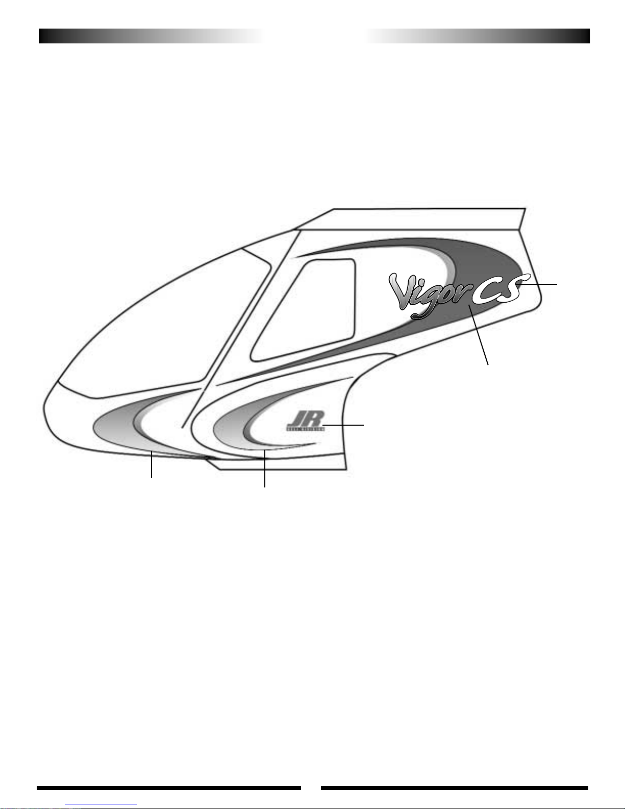
64
E
A
C
D
G
F
DECAL PLACEMENT
™
Page 65
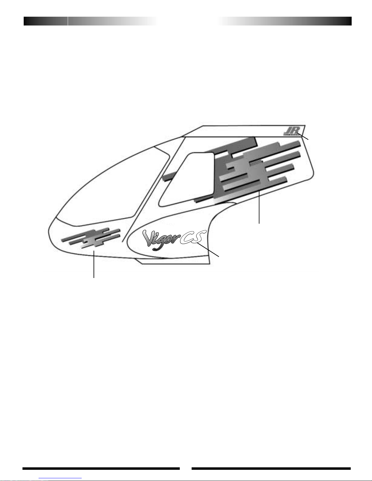
65
B
3
2
5
1
DECAL PLACEMENT
™
Page 66
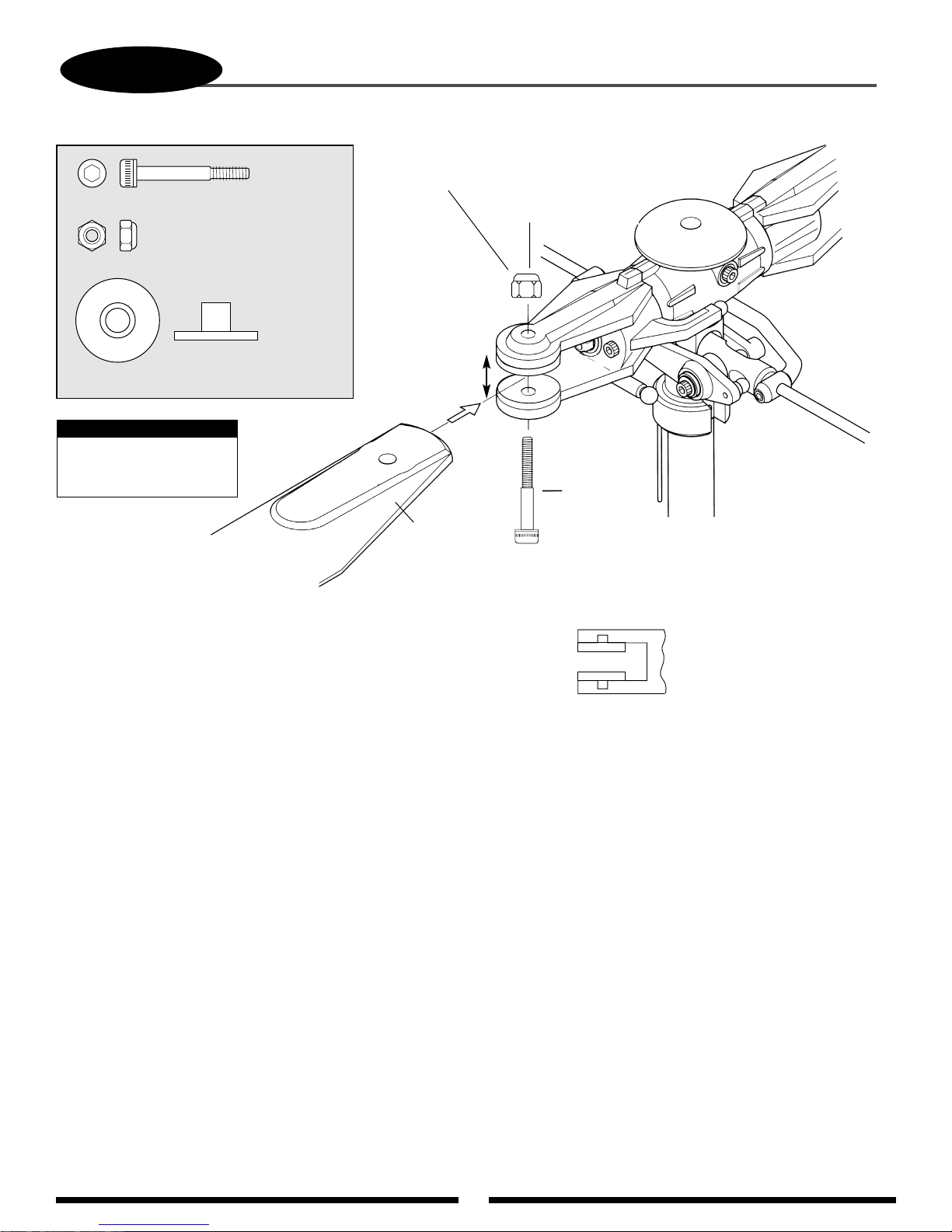
66
8-4
Firmly secure the main
rotor blades to the rotor
head as shown above. Be
sure to note the proper
direction of the rotor
blades when assembling
(clockwise rotation). Main
blades should be tightened
so they can pivot when
moderate pressure is
applied. Do not allow the
main blades to swing
freely within the main
blade holders.
Socket
Head Bolt,
4 x 35 mm
(1 pc)
Not included,
order NOH680C
or NOH700S
12 mm
Insert the main rotor blade spacers as shown.
Apply a light drop of CA
adhesive to hold the main
rotor blade spacers in place.
Lock Nut, 4 mm (1 pc)
Hold the 4 mm Lock Nut while tightening
using a Wiha 7 mm Nut Driver or equivalent.
Two sets required
MAIN ROTOR BLADE ATTACHMENT (BLADES NOT INCLUDED)
............2 pcs
Socket Head Bolt, 4 x 35 mm
.........................................2 pcs
Lock Nut, 4 mm
...................................4 pcs
Main Roter Blade Spacers (12 mm Grip)
Note:
5 x 35 mm bolts and
5mm nuts are also
included with this kit.
Page 67
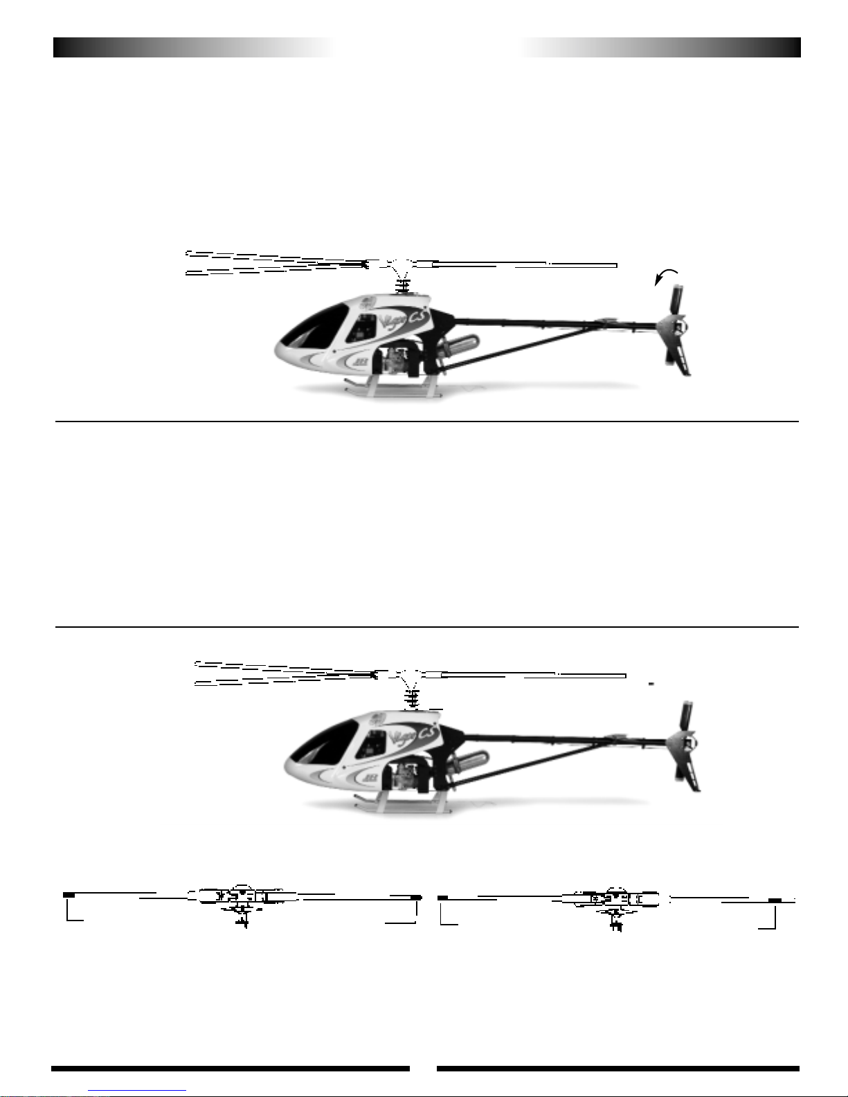
Once all assemblies have been completed, please review the following
suggestions before attempting initial flights.
• Review the instruction book and confirm that all assembly steps have
been completed thoroughly.
• Check to insure that all servos are operating smoothly and in the
correct direction. Also verify that there is no binding in the control rods
and that each servo horn is secured with a servo horn mounting screw.
• Check to insure that all bolts and screws have been completely tightened
and secured with threadlock where indicated.
• Verify that the gyro is operational and compensating in the correct
direction (detailed in Section 7, page 61).
• Make sure that both the transmitter and receiver have been fully
charged (refer to your radio system instructions for proper charging
procedures).
• Check to insure that the throttle is working properly and in the correct
direction.
67
FINAL PREFLIGHT CHECK
BLADE TRACKING IDENTIFICATION
A: Use two different blade tracking tape colors (e.g., black and red) at
the tip of each main rotor blade.
B: Use the same color blade tracking tape located at different positions
on each rotor blade.
Note: Adding additional blade tracking tape to the rotor blades at this stage
will make it necessary to re-static balance the main rotor blades.
Blade Labeling for Tracking Purposes
BLADE TRACKING ADJUSTMENT
Blade “tracking” is an adjustment to the main rotor blade pitch that must be
accomplished during the initial test flights.
Although the blade pitch angle in each blade may appear equal, it is still possible
for a set of main rotor blades to run “out of track,” making adjustment necessary.
Main rotor blades that are out of track with one another can cause vibration,
instability, and a loss of power due to additional drag.
On the initial flight, it will be necessary to increase the blade speed to just before
lift-off rpm and view the rotor disc at eye level from a safe distance
(approximately 15 to 20 feet).
Note which blade is running low (by colored tracking tape) and increase the pitch
of the low blade one turn of the ball link at a time until each blade runs in track
(on the same plane).
Please refer to the diagrams below to identify the different tracking situations, as
well as several methods to mark each rotor blade for tracking identification.
Incorrect
Out of Track
Correct
In Track
Caution: Be sure to maintain a safe distance from the helicopter
(15 to 20 feet) when tracking main rotor blades.
Adjustment is necessary.
A
Red
Black
B
Red Red
Rotate the main rotor counter clockwise (backward)
and note the rotation of the tail rotor.
Correct Main/Tail Rotor Rotation Direction
Adjustment is not necessary.
Page 68

68
Engine
After each day of flying, fully drain the fuel tank. Then start the engine
and let it idle until the engine and the fuel line are completely burned off. It is
also suggested that an after-run oil be used to prevent premature engine
corrosion.
Check All Nuts and Bolts
A helicopter is subject to high vibration during flight. It is important
to check that all screws, nuts and bolts are properly secured after each
day of flying. It is also suggested that you perform a “quick” inspection
between each initial test flight for approximately the first 6 to 10 flights.
Main Rotor Head
It will be necessary for the main rotor head dampners to be checked/and or
replaced every 30–50 flights to maintain maximum rotor head performance.
When replacing the main rotor head dampners, apply a light coating of oil to the
dampners to prolong life.
It is also suggested at this time that the rotor head thrust bearings be
lubricated using a high speed grease. This will prolong the visibility of the thrust
bearings.
Tail Gear Case
The tail gear case should be repacked with grease every 50 or so flights. the
tail pitch slider and mechanism should be oiled lightly every 5–10 flights to help
reduce wear.
Washout Base
Lubricate the washout base using light oil every 10–15 flights to insure
smooth operating and reduce wear. Inspect the washout base every 50–75 flights.
If excess wear is noted, replace as needed.
Tail Pitch Slider
Lubricate the tail pitch slider using light oil every 5–10 flights to insure
smooth operation and reduce wear.
Check Ball Link Wear
Check to insure that all universal links fit freely but securely to the
control balls. If there is excessive play noted, adjust and or replace the universal
link in question.
Battery Maintenance
Check to insure that your batteries are properly mounted and charged.
The most frequent cause of crashes (aside from pilot error) is battery failure or
disconnection. Be certain that your batteries are fully charged and limit your
flight time to 3 or 4 flights between charging. If more flight time is required,
purchase a reliable quick field charger.
Cleaning
At the end of each flight or flying session, wipe down your helicopter with
a clean towel or rag. This is also a good time to inspect all parts for tightness or
fatigue. Remember, a clean, well-maintained helicopter will provide you with
many hours of trouble-free flight.
Ball Links
Check ball links every 15–20 flights for increased play and looseness.
Adjust the ball links using plyers to tighten the ball race if needed.
GENERAL MAINTENANCE
Page 69
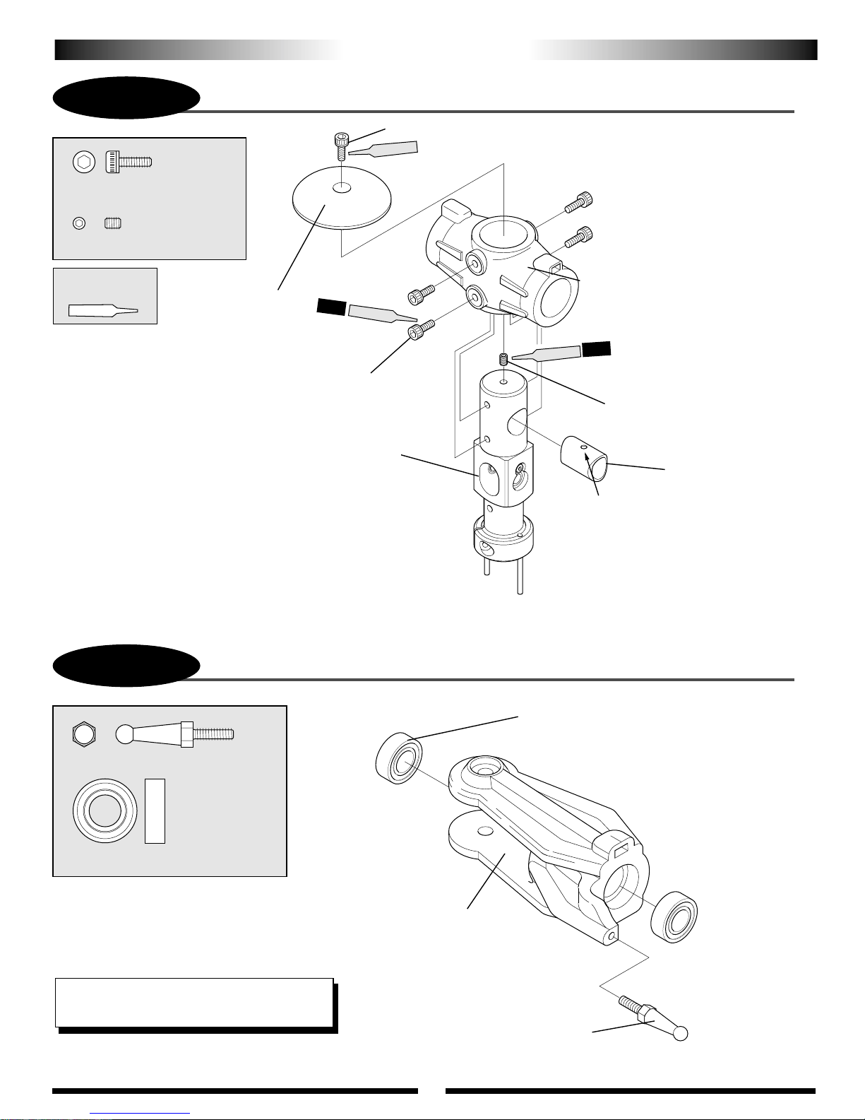
69
PREASSEMBLED COMPONENTS
P-1
................5 pcs
Socket Head Bolt, 3 x 8 mm
.........................1 pc
Set Screw, 3 x 4 mm
Use Red
Threadlock
Socket Head Bolt, 3 x 8 mm (4 pcs)
ASSEMBLY PROCESS – MAIN ROTOR HEAD 1
Socket Head Bolt, 3 x 8 mm
Red
Head Button
Main Rotor Hub Assembly
4 pcs
Red
Red
Main Rotor Head Body
ALL
Set Screw, 3 x 4 mm
Spindle Shaft Guide
Position hole at top to
engage set screw.
P-2
Control Ball, 14 mm
......................4 pcs
Bearing, 8 x 16 x 5 mm
Use caution when inserting the
main blade holder bearings so
as not to distort/damage the
main blade holders.
Make two main blade holders.
TEAM TIP: JB Weld the bearings into the blade
holders to reduce play in the blade holders.
ASSEMBLY PROCESS – MAIN ROTOR HEAD 2
...2 pcs
Bearing, 8 x 16 x 5 mm (4 pcs)
Main Blade Holder
Control Ball, 14mm (2 pcs)
Page 70

70
P-3
ASSEMBLY PROCESS PARTS – MAIN ROTOR HEAD 3
.....2 pcs
Socket Head Bolt, 5 x 10 mm
..............2 pcs
Thrust Bearing, 8 x 16 x 5 mm
...................2 pcs
Spindle Washer (Black)
...................2 pcs
Blade Holder Spacer (Silver)
..................2 pcs
Washer, 12 x 16 x 0.5 mm
Use Red
Threadlock
Washer, 12 x 16 x 0.5 mm (2 pcs)
Grease thrust bearings
during assembly to prolong life
Blade Spindle Shaft
Large I.D.
Small I.D.
Blade Dampener Rubber (2 pcs)
(check after approx. 30-50
flights and replace as needed)
Blade Holder
Spacer (Silver)(2 pcs)
Be sure to note correct
placement of
large/small I.D. thrust
washers during
assembly.
Grease thrust bearings
before assembly
2 pcs
Red
...2 pcs
Blade Dampener Rubber (#50)
P-4
...................2 pcs
Button Head Bolt, 3 x 5 mm
.......................2 pcs
Seesaw Spacer Collar
Be sure to note correct
*
placement of the front
and the back of the
seesaw assembly.
ASSEMBLY PROCESS - MAIN ROTOR HEAD 4
Thrust Bearing, 8 x 16 x 5 mm (2 pcs)
Spindle Washer (Black) (2 pcs)
Socket Head Bolt, 5 x 10 mm (2 pcs)
Button Head Bolt, 3 x 5 mm (2 pcs)
Seesaw Spacer Collar (2 pcs)
Seesaw Assembly
*
2 pcs
Red
Page 71
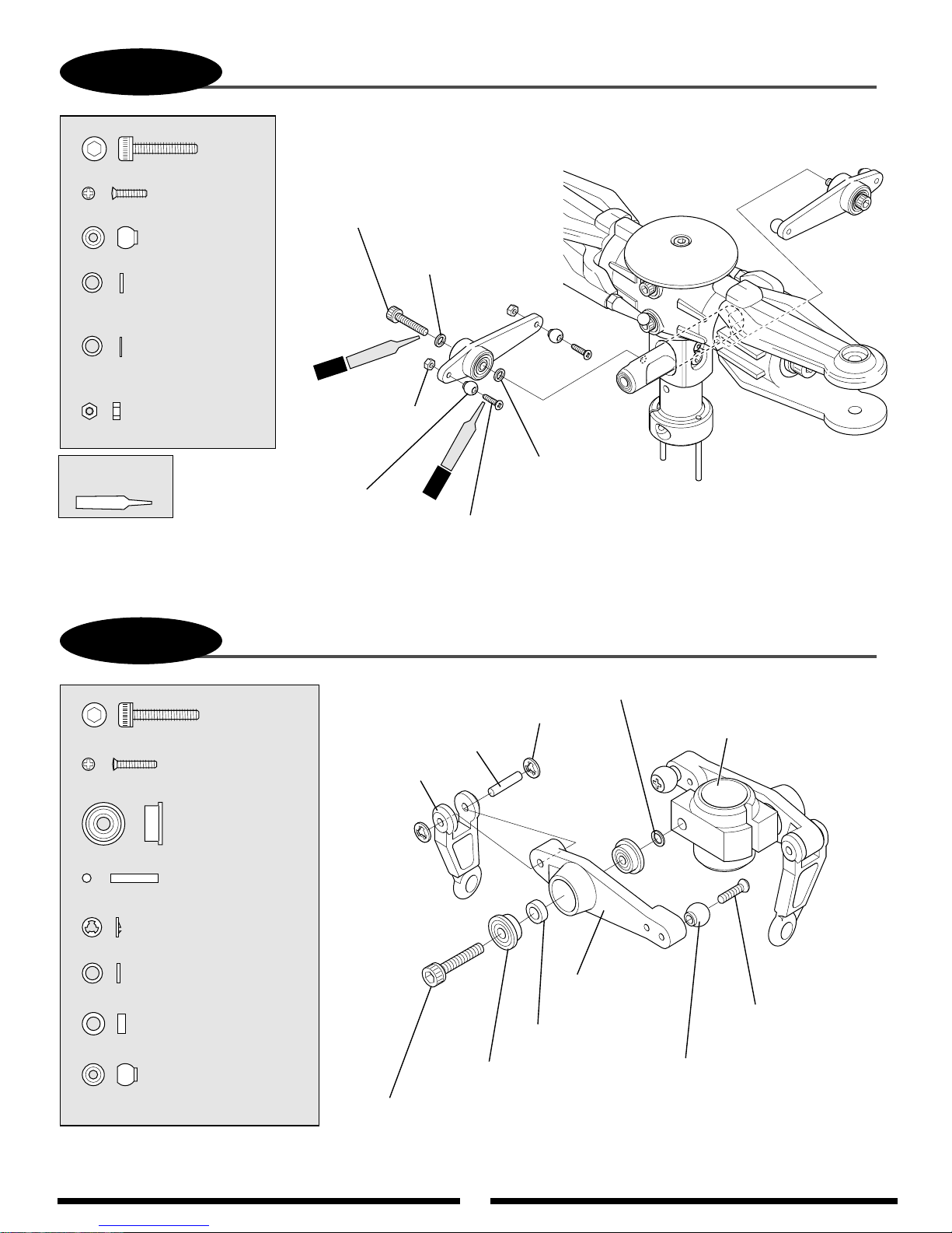
71
P-5
Socket Head Bolt, 3 x 15 mm
,.....................4 pcs
Flat Head Screw, 2 x 8 mm
.......................4 pcs
Steel Joint Ball
...........................2 pcs
Washer, 3 x 4.5 x 0.7 mm
(Thickness 0.7 mm)
ASSEMBLY PROCESS – MAIN ROTOR HEAD
........2 pcs
Socket Head Bolt, 3 x 15 mm (2 pcs)
Washer, 3 x 4.5 x 0.4 mm (2 pcs)
(Thickness 0.4 mm)
...........................2 pcs
Washer, 3 x 4.5 x 0.4 mm
(Thickness 0.4 mm)
...........................4 pcs
Hex Nut, 2 mm
Use Red
Threadlock
P-6
Socket Head Bolt, 3 x 15 mm
..........................2 pcs
Flat Head Screw, 2 x 10 mm
Steel Joint Ball (2 pcs)
ASSEMBLY PROCESS – WASHOUT UNIT
...............2 pcs
Red
2pcs
Hex Nut, 2 mm (4 pcs)
Flat Head Screw, 2 x 8 mm (4 pcs)
CA Stopper Ring, 2mm (4 pcs)
Washout Link Pin (2 pcs)
Washout Link
4pcs
Red
Washer, 3 x 4.5 x 0.7 mm
(2 pcs)
(Thickness 0.7 mm)
Washer, 3 x 4.5 x 0.4 mm (2 pcs)
Washout Base
.........................4 pcs
Flange Bearing, 3 x 8 x 4 mm
..........................2 pcs
Washout Link Pin
...................................4 pcs
CA Stopper Ring, 2 mm
...................................2 pcs
Washer, 3 x 4.5 x 0.4 mm
..................................2 pcs
Spacer, 3 x 5 x 1.8 mm
...............................2 pcs
Steel Joint Ball
Spacer, 3 x 5 x 1.8 mm
(2 pcs)
Flange Bearing, 3 x 8 x 4 mm (4 pcs)
Socket Head Bolt, 3 x 15 mm (2 pcs)
Washout Arm
Flat Head Screw,
2 x 10 mm (2 pcs)
Steel Joint Ball (2 pcs)
Page 72
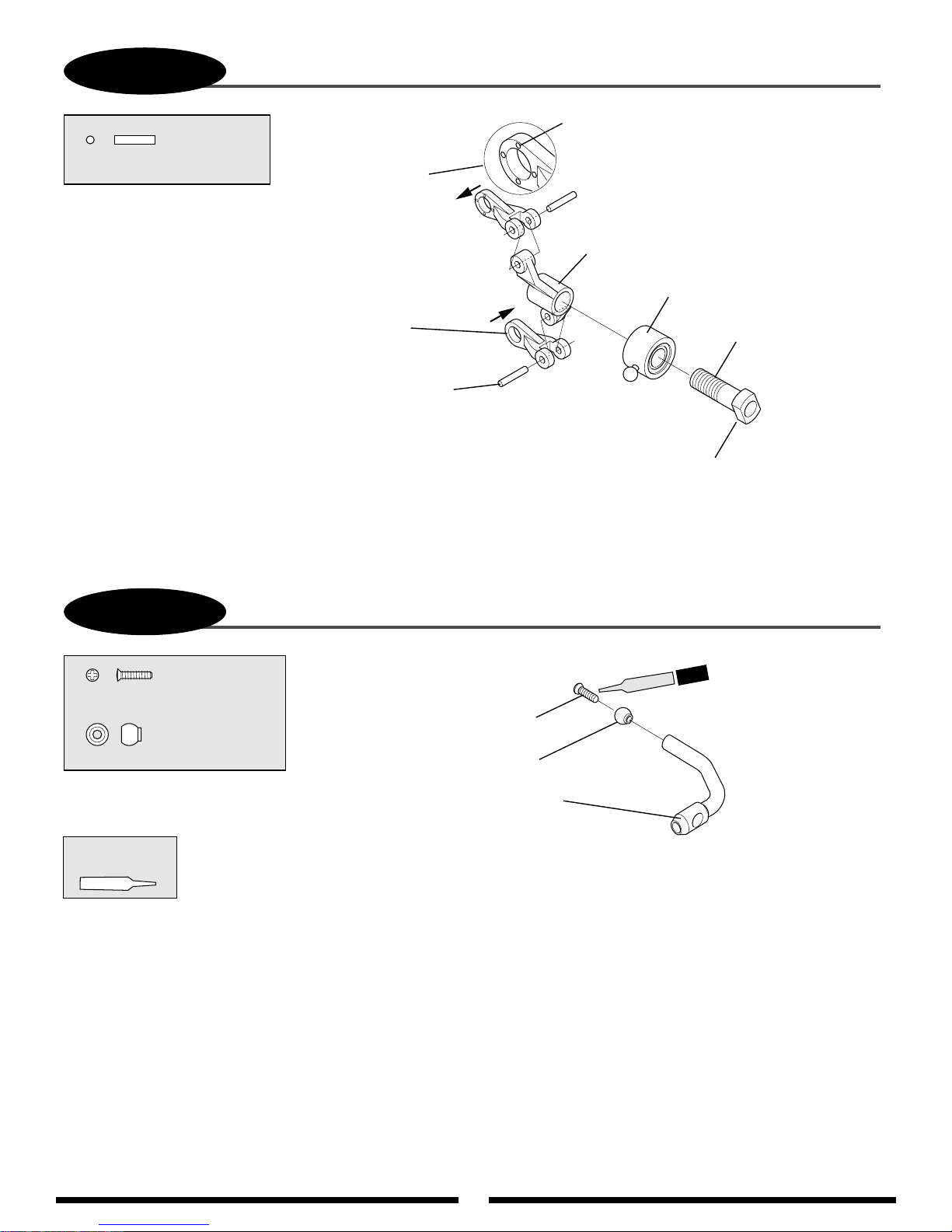
72
P-7
ASSEMBLY PROCESS – TAIL SLIDE RING
..................2 pcs
Tail Pitch Link Pin
Installing with four
moulded circle marks
in link facing in the
direction of arrow as
shown.
Tail Pitch Link (2 pcs)
Tail Pitch Link Pin (2 pcs)
Be sure to center Pin
between pitch link ears
when installing.
Circle Marks
Tail Pitch Plate
Tail Slide Ring Collar w/Bearing
Tail Slide Ring Sleeve
Tail slide ting sleeve is
reverse (left hand) thread.
Use caution when
installing.
P-8
........................2 pcs
Flat Head Screw, 2 x 8 mm
...........................2 pcs
Steel Joint Ball
Make two flybar control arms.
Use Red
Threadlock
ASSEMBLY PROCESS – FLYBAR CONTROL ARM
Flat Head Screw, 2 x 8 mm (2 pcs)
Steel Joint Ball (2 pcs)
Flybar Control Arm
Red
2 pcs
Page 73
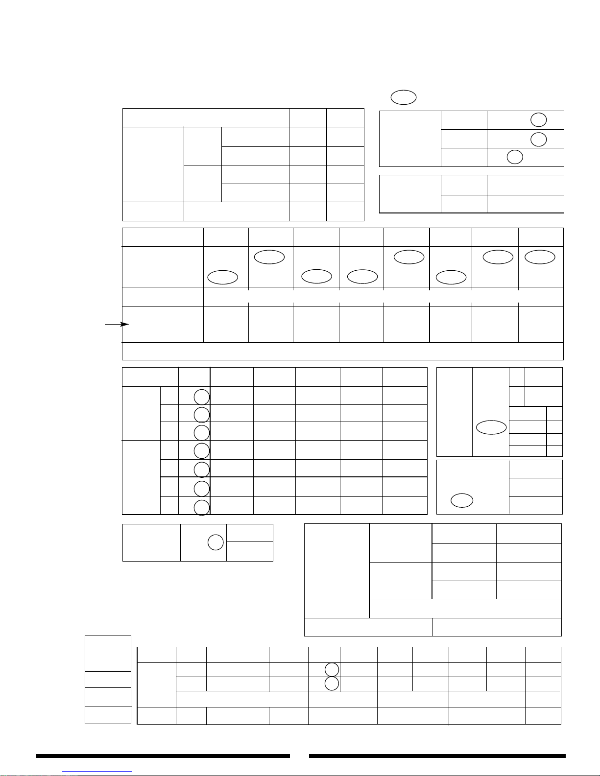
73
EXP L 1 2 3 H
N
OFF•ON
0% 38% 44% 50% 100%
1
OFF•ON
100% 84% 60% 86% 100%
2
OFF•ON
100% 84% 60% 86% 100%
N
OFF•ON
0° 28% 59% 75% 97%
1
OFF•ON
0° 26% 53% 80% 98%
2
OFF•ON
0° 26% 53% 80% 98%
H
OFF•ON
0° 30% 60% 80% 100%
1
XP8103 Curtis Vigor™CS Program 120° CCPM
as Contained on the DataSafe Disk
MODEL NO. ____________________________________
MODEL NAME ____________________________________
MODULATION SPCM - ZPCM - PPM __________________
EQUIPMENT:
Gyro: JR G5000T or G550T
Engine: OS 61SXH WC
Muffler: YEI Muscle Pipe
Servos: JR Digital
AILE ELEV RUDD
D/R 100% 100% 100%
EXP 0% 0% +45%
D/R 100% 100% 100%
EXP 0% 0% +65%
0
040
30
%
%
Set for Idle
POS
REVO
MIX
TRIM STEP
SYSTEM
MODE
ACC MIX
NORMAL
NORM 0
STNT 1
HOLD 0
INVT
AIL +48%
ELEV +52%
PIT +60%
UP 0°
DOWN 0°
UP 0°
DOWN 0°
GYRO
SENS
SWASH MIX
3 SERVO
120°
EXP ACT
INH
•
RUDD D/R
•
AUTO
STUNT
PROGRAM
MIX
THROTTLE
CURVE
Throttle travel
must be set to
150% if program
mixing is to be
used.
PITCH
CURVE
THRO HOLD INH • ACT
CHANNEL SW EXP L 1 2 3 H SW
MIX1 AILE→THRO ON OFF-ON 20 – 0 – 20 F-S12
MIX2 ELEV→THRO ON OFF-ON 20 – 0 – 20 F-S12
+POS -POS OFFSET
MIX3 ELEV→AILE +14% +14% 0 F-S12
REVERSE SW
SUB-TRIM
TRAVEL ADJUST
FAIL SAFE (SPCM)
THRO AILE ELEV RUDD GEAR PIT AUX2 AUX3
NORM NORM NORM NORM NORM NORM NORM NORM
•• •••• ••
REV REV REV REV REV REV REV REV
H 150% L 115% D 115% L 150% + 100% H 115% + 150% + 150%
L 150% R 115% U 115% R 150% - 100% L 115% - 150% - 150%
DUAL-RATE
•
EXP
AUTO
D/R
(POS. 1)
ST1 INH • ACT
ST2 INH • ACT
HOLD INH • ACT
AUX2
HOLD SW
• PIT.TRIM•INH
GEAR ACT • INH
INPUT
SEL
1
VIGOR CS
ADJUST SO THAT NO TRIM IS REQUIRED
SET TO DESIRED SETTINGS
AIL 4
ELEV 1
RUDD 1
Page 74
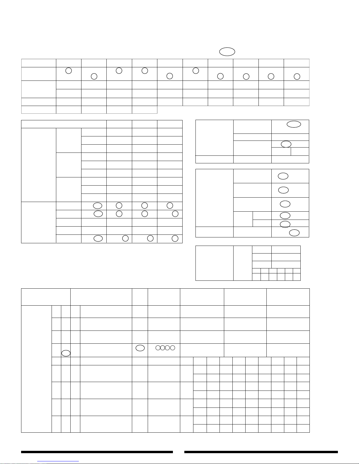
AILE ELEV RUDD
D/R 100 % 100 % 90 %
0 EXP 0 % 0 % +60 %
TYPE LIN/EXP LIN/EXP LIN/EXP
D/R 100 % 100 % 100 %
1 EXP 0 % 0 % +70 %
TYPE LIN/EXP LIN/EXP LIN/EXP
D/R 100 % 100 % 100 %
2 EXP 0% 0% +45%
TYPE LIN/EXP LIN/EXP LIN/EXP
ST-1 INH•ACT 0 •1 •20 •1 •20 •1 •2
ST-2 INH•ACT 0 •1 •20 •1 •20 •1 •2
ST-3 INH•ACT 0 •1 •20 •1 •20 •1 •2
ST-4 INH•ACT 0 •1 •20 •1 •20 •1 •2
HOLD INH•ACT 0 •1 •20 •1 •20 •1 •2
0
1
2
NR S1 S2 S3 S4 HD
0111 12
74
10X Curtis Vigor™CS Program 140° CCPM as Contained on the DataSafe Disk
THRO AILE ELEV RUDD GEAR PITCH AUX2 AUX3 AUX4 AUX5
RRRRRRRRRR
NNNNNNNNNN
H 125% L 115 % D 115 % L 150 % + 100 % + 115 % + 150 % + 150 % + 150 % + 150 %
L 125% R 115 % U 115 % R 150 % – 100 % – 115 % – 150 % – 150 % – 150 % – 150 %
60 % 4 1 1
REVERSE SW (11)
TRAVEL ADJUST
(12)
SUB-TRIM (15)
TRIM RATE (83)
D/R
EXP
(13)
AUTO
D/R
(23)
PROGRAM
MIX
(51) - (58)
HOLD
INH•
HOLD
SW GEAR
POS
AUTO CUT INH•
ACT
POS
Delay 1/4 1/2 3/4 1
FLIGHT
INH
•
GEAR
EXTRA AILE
GEAR
INH
•
GEAR
SW HOLD
AUX2
INH•ACT
SW
PIT.
LOW INH•ACT
LEVER
HI INH•ACT
ADT STUNT INH•ACT
THROTTLE
HOLD
(16)
INH
•
AUX 3
•
AUTO
GYRO
SENS
(44)
FUNCTION
SELECT
(17)
CHANNEL
TRIM SW OFFSET +GAIN –GAIN
MASTER SLAVE
INH OFF NR•S1•S2•S3•S4
51
•
→
•
ACT ON HD•AX2•GER
INH OFF NR
•S1•S2•S3•
S4
52
•
→
•
ACT ON HD•AX2•GER
INH OFF NR
•S1•S2•S3•
S4
53
•
→
•
ACT ON HD•AX2•GER
INH OFF NR
•S1•S2•S3•
S4
54
•
→
•
ACT ON HD•AX2•GER
EXP L 1 2 3 4 5 6 H
INH OFF NR•S1•S2•S3•S4 OFF IN 0 100
55
•
→
••
ACT ON HD•AX2•GER ON OUT
INH OFF NR•S1•S2•S3•S4 OFF IN
0 100
56
•
→
••
ACT ON HD•AX2•GER ON OUT
INH OFF NR
•S1•S2•S3•
S4 OFF IN 0 100
57
•
→
••
ACT ON HD•AX2•GER ON OUT
INH OFF NR•S1•S2•S3•S4 OFF IN
0 100
58
•
→
••
ACT ON HD•AX2•GER ON OUT
MODEL NO. (84) _____________________________________
MODEL NAME (81) ___________________________________
MODULATION (85) SPCM-ZPCM-PPM
JR Vigor CS 140
Adjust for idle
40
30
40
ELEV AILE 0 +14 +14
EQUIPMENT:
Gyro: JR G5000T or G550T
Engine: OS 61SXH WC
Muffler: YEI Muscle Pipe
Servos: JR Digital
Page 75
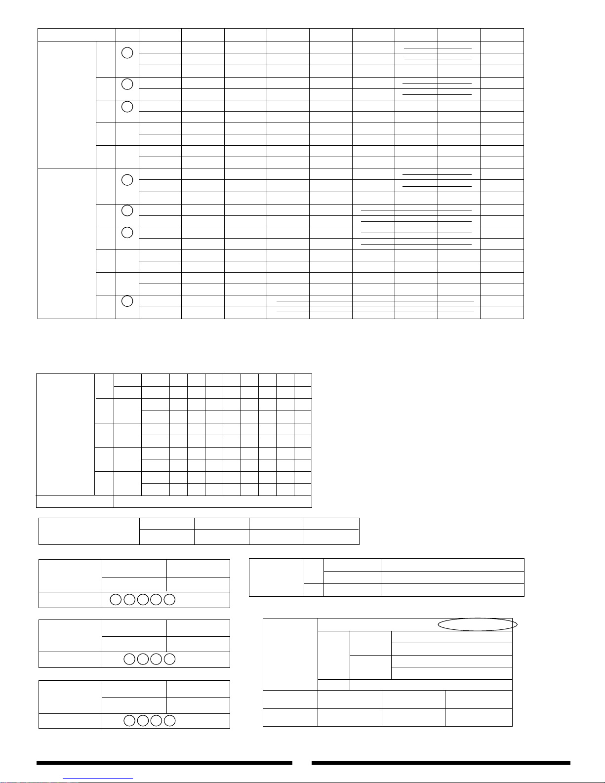
EXP L 1 2 3 4 5 6 H
OFF
IN 0 14 28 74 88 100
N
•
OUT 0 29 38 50 56 100
ON
HOV.SEL
——
HOV HOV HOV HOV HOV HOV
——
1
OFF IN 0 25 48 74 88 100
•
ON OUT 100 84 60 86 94 100
2
OFF IN 0 25 48 74 88 100
•
ON OUT 100 84 60 86 94 100
3
OFF IN 0 100
•
ON OUT
4
OFF IN 0 100
•
ON OUT
OFF
IN 0 13 26 39 80 100
N
•
OUT 0 16 27 51 78 97
ON
HOV.SEL
——
HOV HOV HOV HOV HOV HOV
——
1
OFF IN 0 50 65 85 100
•
ON OUT 0 52 69 88 98
2
OFF IN 0 50 65 85 100
•
ON OUT 0 52 69 88 98
3
OFF IN 0 100
•
ON OUT
4
OFF IN 0 100
•
ON OUT
HOLD
OFF IN 0 50 100
•
ON OUT 0 60 100
THRO
CURVE
(18)
TH,TRIM=SLOW
HOV.T=CENTER
PITCH
CURVE
(68)
P,TRIM=CENTER
HOV.P=CENTER
75
1 SERVO • 3SERVO - 120°CCPM • 3SERVO - 140°CCPM
ELE → AIL
D0 %
1SERVO
U0 %
AIL → ELE
L0 %
R0 %
SWITCH NR
• S1 • S2 • S3 • S4 • HD
3 SERVO
AIL % ELE % PIT %
120° CCPM
3 SERVO
AIL % ELE % PIT %
140° CCPM
SWASHPLATE
MIXING
TYPE
(65)
TRIM OFFSET
HV.T HV.P LO.P HI.P
(82)
N
NOR IN L 1 2 3 4 5 6 H
ORG OUT
1
NOR IN 100
ORG OUT
2
NOR IN 100
ORG OUT
3
NOR IN 100
ORG OUT
4
NOR IN 100
ORG OUT
MIX RATE 1/1
•
1/2 •1/4 •1/10
TAIL
ROTOR
CURVE
(47)
Z
MODE HOLD • 1.0s • 0.5s • 0.25s
MEMORY
S MEMORY
FAILSAFE
(77)
+15 %
-15
%
MODE SELECTION NR •S1 •S2 •S3 •S4 •AX2
Rudder→Throttle
4→1
MIX (41)
+20 %
-20 %
MODE SELECTION NR
•
S1 •S2 •S3 •S4 •AX2
Aileron→Throttle
2→1
MIX (42)
+20
-20
MODE SELECTION NR
•
S1 •S2 •S3 •S4 •AX2
Elevator→Throttle
3→1
MIX (43)
Throttle at 1/4 stick
+48 +52 +60
Page 76
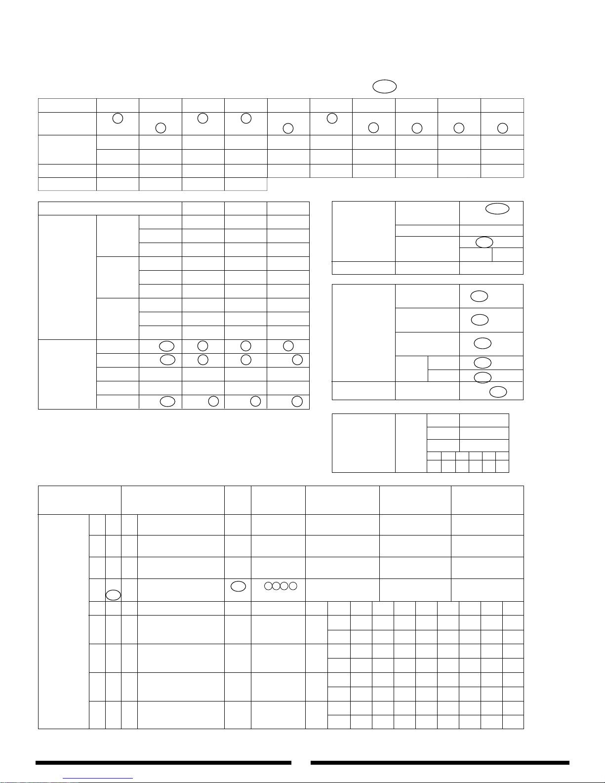
76
AILE ELEV RUDD
D/R 100 % 100 % 90 %
0 EXP 0 % 0 % +60 %
TYPE LIN/EXP LIN/EXP LIN/EXP
D/R 100 % 100 % 100 %
1 EXP 0 % 0 % +70 %
TYPE LIN/EXP LIN/EXP LIN/EXP
D/R 100 % 100 % 100 %
2 EXP 0% 0% +45%
TYPE LIN/EXP LIN/EXP LIN/EXP
ST-1 INH•ACT 0 •1 •20 •1 •20 •1 •2
ST-2 INH•ACT 0 •1 •20 •1 •20 •1 •2
ST-3 INH•ACT 0 •1 •20 •1 •20 •1 •2
ST-4 INH•ACT 0 •1 •20 •1 •20 •1 •2
HOLD INH•ACT 0 •1 •20 •1 •20 •1 •2
0
1
2
NR S1 S2 S3 S4 HD
0111 12
10X Curtis Vigor™CS Program 120° CCPM as Contained on the DataSafe Disk
THRO AILE ELEV RUDD GEAR PITCH AUX2 AUX3 AUX4 AUX5
RRRRRRRRRR
NNNNNNNNNN
H 125% L 115 % D 115 % L 150 % + 100 % + 115 % + 150 % + 150 % + 150 % + 150 %
L 125% R 115 % U 115 % R 150 % – 100 % – 115 % – 150 % – 150 % – 150 % – 150 %
60 % 4 1 1
REVERSE SW (11)
TRAVEL ADJUST
(12)
SUB-TRIM (15)
TRIM RATE (83)
D/R
EXP
(13)
AUTO
D/R
(23)
PROGRAM
MIX
(51) - (58)
HOLD
INH•
HOLD
SW GEAR
POS
AUTO CUT INH•
ACT
POS
Delay 1/4 1/2 3/4 1
FLIGHT
INH
•
GEAR
EXTRA AILE
GEAR
INH
•
GEAR
SW HOLD
AUX2
INH•ACT
SW
PIT.
LOW INH•ACT
LEVER
HI INH•ACT
ADT STUNT INH•ACT
THROTTLE
HOLD
(16)
INH
•
AUX 3
•
AUTO
GYRO
SENS
(44)
FUNCTION
SELECT
(17)
CHANNEL
TRIM SW OFFSET +GAIN –GAIN
MASTER SLAVE
INH OFF NR•S1•S2•S3•S4
51
•
→
•
ACT ON HD•AX2•GER
INH OFF NR
•S1•S2•S3•
S4
52
•
→
•
ACT ON HD•AX2•GER
INH OFF NR
•S1•S2•S3•
S4
53
•
→
•
ACT ON HD•AX2•GER
INH OFF NR
•S1•S2•S3•
S4
54
•
→
•
ACT ON HD•AX2•GER
EXP L 1 2 3 4 5 6 H
INH OFF NR•S1•S2•S3•S4 OFF IN 0 100
55
•
→
••
ACT ON HD•AX2•GER ON OUT
INH OFF NR•S1•S2•S3•S4 OFF IN 0 100
56
•
→
••
ACT ON HD•AX2•GER ON OUT
INH OFF NR•S1•S2•S3•S4 OFF IN 0 100
57
•
→
••
ACT ON HD•AX2•GER ON OUT
INH OFF NR•S1•S2•S3•S4 OFF IN 0 100
58
•
→
••
ACT ON HD•AX2•GER ON OUT
MODEL NO. (84) _____________________________________
MODEL NAME (81) ___________________________________
MODULATION (85) SPCM-ZPCM-PPM
JR Vigor CS 120
Adjust for idle
40
30
40
ELEV AILE 0 +14 +14
EQUIPMENT:
Gyro: JR G5000T or G550T
Engine: OS 61SXH WC
Muffler: YEI Muscle Pipe
Servos: JR Digital
Page 77

77
EXP L 1 2 3 4 5 6 H
OFF
IN 0 14 28 74 88 100
N
•
OUT 0 29 38 50 56 100
ON
HOV.SEL
——
HOV HOV HOV HOV HOV HOV
——
1
OFF IN 0 25 48 74 88 100
•
ON OUT 100 84 60 86 94 100
2
OFF IN 0 25 48 74 88 100
•
ON OUT 100 84 60 86 94 100
3
OFF IN 0 13 26 39 80 100
•
ON OUT 0 16 27 51 78 97
4
OFF IN 0 100
•
ON OUT
OFF
IN 0 13 26 39 80 100
N
•
OUT 0 16 27 51 78 97
ON
HOV.SEL
——
HOV HOV HOV HOV HOV HOV
——
1
OFF IN 0 50 65 85 100
•
ON OUT 0 52 69 88 98
2
OFF IN 0 50 65 85 100
•
ON OUT 0 52 69 88 98
3
OFF IN 0 100
•
ON OUT
4
OFF IN 0 100
•
ON OUT
HOLD
OFF IN 0 50 100
•
ON OUT 0 60 100
THRO
CURVE
(18)
TH,TRIM=SLOW
HOV.T=CENTER
PITCH
CURVE
(68)
P,TRIM=CENTER
HOV.P=CENTER
1 SERVO
• 3SERVO - 120°CCPM • 3SERVO - 140°CCPM
ELE → AIL
D%
1SERVO
U%
AIL → ELE
L%
R%
SWITCH NR
• S1 • S2 • S3 • S4 • HD
3 SERVO
AIL % ELE % PIT %
120° CCPM
3 SERVO
AIL % ELE % PIT %
140° CCPM
SWASHPLATE
MIXING
TYPE
(65)
TRIM OFFSET
HV.T HV.P LO.P HI.P
(82)
N
NOR IN L 1 2 3 4 5 6 H
ORG OUT
1
NOR IN 100
ORG OUT
2
NOR IN 100
ORG OUT
3
NOR IN 100
ORG OUT
4
NOR IN 100
ORG OUT
MIX RATE 1/1
•
1/2 •1/4 •1/10
TAIL
ROTOR
CURVE
(47)
Z
MODE HOLD • 1.0s • 0.5s • 0.25s
MEMORY
S MEMORY THROTTLE 1/4 STICK
FAIL-
SAFE
(77)
+15 %
-15
%
MODE SELECTION NR •S1 •S2 •S3 •S4 •AX2
Rudder→Throttle
4→1
MIX (41)
+20 %
-20 %
MODE SELECTION NR •S1 •S2 •S3 •S4 •AX2
Aileron→Throttle
2→1
MIX (42)
+20 %
-20 %
MODE SELECTION NR
•
S1 •S2 •S3 •S4 •AX2
Elevator→Throttle
3→1
MIX (43)
+48 +52 +60
Page 78

78
START SHAFT/ CLUTCH/ ENGINE ASSEMBLY
™
JRP981005
JRP970031
JRP996016
JRP980036
JRP980059
JRP960005
JRP980004
JRP981025
JRP960157
JRP980036
JRP980013
JRP991001
JRP996013
JRP996017
JRP970080
JRP960471
JRP960121
JRP981005
JRP980062
JRP970050
JRP996006
JRP980029
JRP980036
JRP996002
JRP980036
JRP980039
JRP970102
JRP996014
JRP980012
JRP980036
JRP996003
JRP996011
JRP980062
JRP996002
JRP996006
JRP980036
JRP980029
JRP980026
JRP980106
JRP970004
JRP980071
JRP980064
JRP980036
JRP980122
JRP980022
JRP970001
JRP980037
Page 79

79
VIGOR™CS MANUAL PARTS LISTINGS
Start Shaft/ Clutch/ Engine Assembly
Part # Description Quantity Comments/ Additional Contents
960005 Hex Shaft Adaptor 1 Complete w/two 4 x 4 mm set screws
980004 Set Screw, 4 x 4 mm 10
981025 Bearing, Sealed, 5 x 19 x 6 mm 2
960157 Start Shaft Bearing Block w/BB 1
980036 Flat Washer, 3 mm 10
980013 Socket Head Bolt, 3 x 8 mm 10
996017 Clutch Bell Assembly w/BB 1 Complete w/bearing & clutch lining
970080 clutch lining 1
960471 Start Shaft 1
960121 Clutch Assembly 1 Complete w/two 4 x 6 mm bolts
980062 Socket Head Bolt, 4 x 6 mm 10
981005 Ball Bearing, 10 x 19 x 7 mm 2
970031 Pinion Gear, 9 Tooth 1
991001 Ball Bearing, 15 x 24 x 5 mm 1
996013 Long Bearing Block “B” 1 Complete w/bearing
996016 Long Bearing Block “A” 1 Complete w/bearing
980059 Socket Head Bolt, 3 x 14 mm 10
970050 Taper Collet “B”, Upper 1
996006 Cooling Fan Shroud 1 1-left, 1-right half Complete w/screws
996002 Cooling Shroud Brackets 2 Complete w/screws and washers
996003 Cooling Fan Blades 1 Complete w/screws and washers
996011 Cooling Fan Hub 1
980062 Socket Head Bolt, 4 x 6 mm 10
980029 Self Tapping Screw, 3 x 12 mm 10
970102 Taper Collet “C”, Lower 1
980039 Nylon Lock Nut, 3 mm Low Profile 10
996014 Engine Mount 1
980022 Socket Head Bolt, 3 x 40 mm 10
980122 Socket Head Bolt, 3 x 50 mm 10
980071 Flat Washer, 4 mm 10
980064 Socket Head Bolt, 4 x 15 mm 10
970001 Steel Joint Ball w/2 x 8 mm Screw 10 Complete w/ten 2 x 8 mm screws
980037 Hex Nut, 2 mm 10
970004 Universal Ball Link 10
Page 80
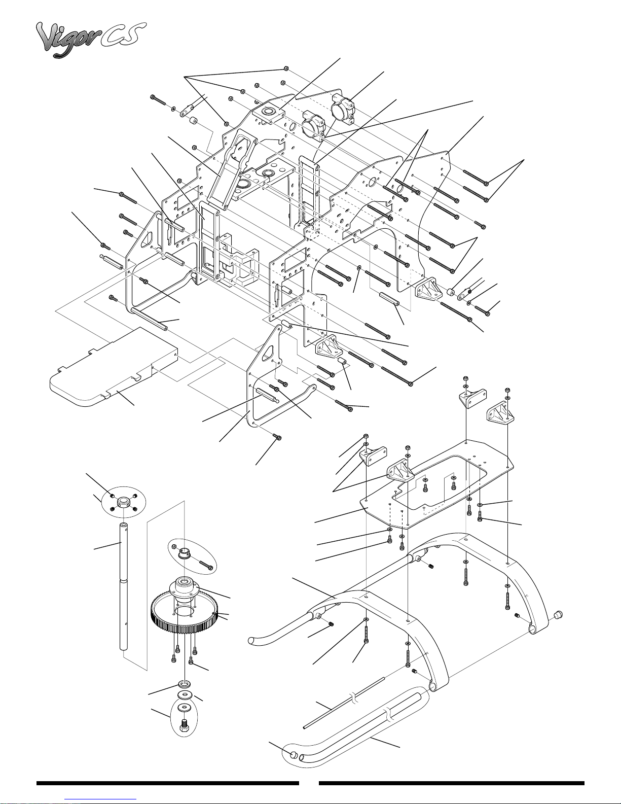
JRP996001
JRP980039
JRP996004
JRP970020
JRP980061
RV01050
JRP980061
JRP970213
JRP980014
JRP980014
JRP980039
JRP980036
JRP996005
JRP980013
JRP970092
JRP960191
JRP980013
JRP970204
RV01051
JRP994009
JRP996009
JRP996004
JRP970020
JRP980036
JRP970094
JRP980122
JRP980019
JRP980122
JRP980022
JRP980022
JRP980022
JRP980036
JRP970018
JRP980036
JRP980036
JRP980012
JRP960338
JRP980004
JRP970008
JRP996012
JRP996015
JRP996030
JRP980012
JRP994001
JRP970047
JRP980004
JRP980036
JRP980060
JRP980014
JRP996018
JRP960036
JRP960119
JRP970048
JRP994010
JRP990053
JRP960504
(CNC)
Driven
Tail Rotor
JRP9940011
80
MAIN FRAME/LANDING GEAR/AUTOROTATION ASSEMBLY
™
Page 81

81
VIGOR™CS MANUAL PARTS LISTINGS
Main Frame/Landing Gear/Autorotation assembly
Part # Description Quantity Comments/ Additional Contents
980039 Nylon Lock Nut, 3 mm Low Profile 10
996009 Upper Main Shaft Bearing Block w/BB 1 Complete with ball bearing
994010 Tail Boom Mounting Clamp 1
994009 Tail Boom Mounting Clamp (Aluminum) 1 Complete w/one 3.5 x 6 & one 3.5 x 8 bolt
996004 I-Beam Crossmember “B” 2
RV01050 Main Frame Set 1 Complete Set (2 pcs)
980022 Socket Head Bolt, 3 x 40 mm 10
996001 I-Beam Crossmember “A” 1
970020 Main Frame Crossmember, 32 mm 2
980061 Socket Head Bolt, 3 x 25 mm 10
980014 Socket Head Bolt, 3 x 10 mm 10
990053 Socket Head Bolt, 3.5 x 6 mm 10
970018 Mixing Lever Spacer 2
980036 Flat Washer, 3 mm 10
980019 Socket Head Bolt, 3 x 22 mm 10
980122 Socket Head Bolt, 3 x 50 mm 10
980013 Socket Head Bolt, 3 x 8 mm 10
970092 Main Frame Crossmember, 64 mm 2
970094 Spacer, 3 x 6 x 14 mm 2
970213 Spacer, 3 x 6 x 10 mm 2
RV01051 Fuel Tank Mounting Frames 2
970204 Canopy Mounting Standoff 2
960191 Front Radio Bed 1
980004 Set Screw, 4 x 4 mm 10
970008 Main Shaft Collar 1 Complete w/four 4 x 4 mm set screws
996012 Main Rotor Shaft 1
996005 Landing Strut Mounts 4
980014 Socket Head Bolt, 3 x 10 mm 10
996018 Carbon Bottom Frame Plate 1
980012 Socket Head Bolt, 3 x 6 mm 10
960338 Landing Struts, white 2
980004 Set Screw, 4 x 4 mm 10
980060 Socket Head Bolt, 3 x 20 mm 10
960036 Antenna Tube 3
960119 Landing Skids 2 Complete w/four skid caps
970048 Landing Skid Caps 4
996015 Autorotation Assembly 1
996030 84T Molded Main Drive Gear 1 (standard)
970047 Main Shaft Washer and Bolt 1 Complete w/one 6 x 10 mm hex bolt
994001 Steel Auto Hub Washer 1
960504 84T CNC Main Drive Gear 1 (optional)
Page 82
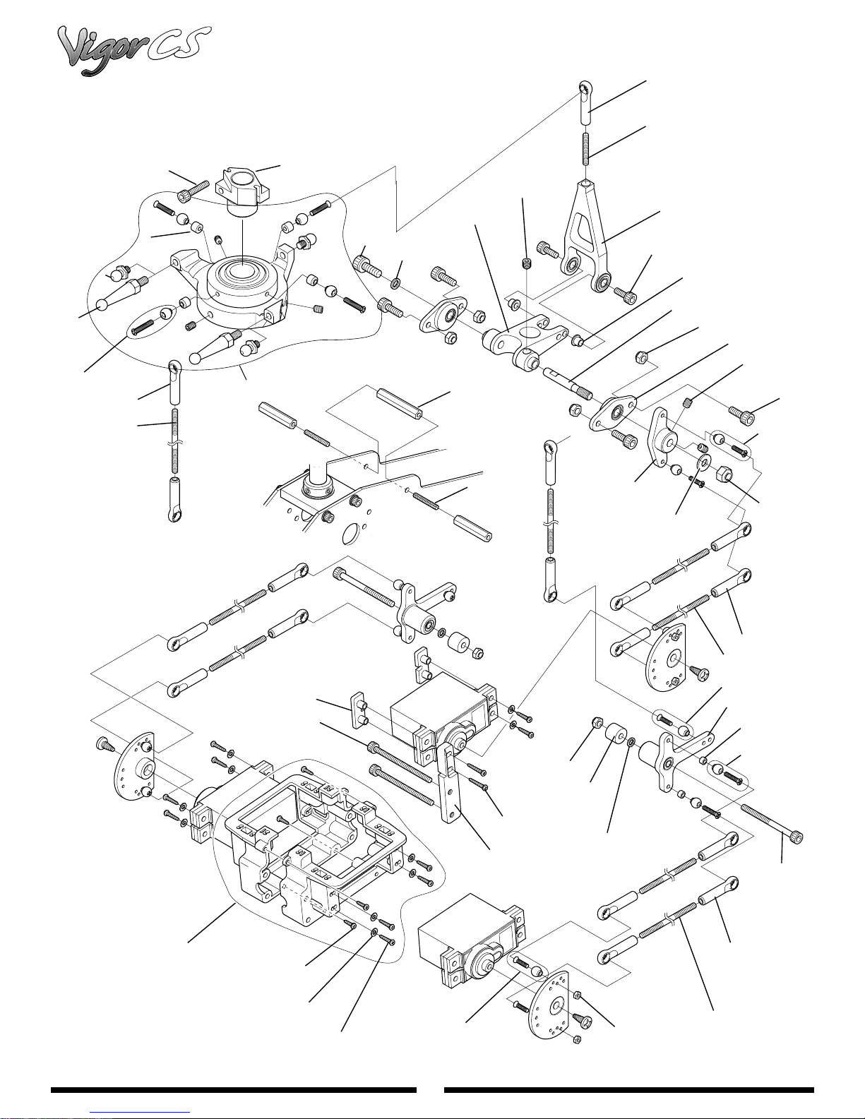
82
SWASHPLATE/CCPM CONTROL SYSTEM
™
JRP994021
JRP980052
JRP970078
JRP970201
JRP994019
JRP970002
JRP970004
JRP980046
JRP980016
JRP996039
JRP996038
JRP980102
JRP970211
JRP996043
JRP970020
JRP980002
JRP980004
JRP996042
JRP980013
JRP970209
JRP994020
JRP980039
JRP991003
JRP980004
JRP980013
JRP970001
JRP994018
JRP980040
JRP980071
JRP996007
JRP970104
JRP980022
JRP980026
JRP980035
JRP980027
JRP970001
JRP980039
JRP970018
JRP980148
JRP996041
JRP970206
JRP980037
JRP970004
JRP980056
JRP970001
JRP996040
JRP970053
JRP970002
JRP980020
JRP970004
JRP980057(L95)
JRP980105(L80)
Page 83

83
VIGOR™CS MANUAL PARTS LISTINGS
Swashplate/CCPM Control System
Part # Description Quantity Comments/ Additional Contents
JRP970001 Joint Balls w/8 mm screws 10
JRP970002 Joint Balls w/10 mm screws 10
JRP970004 Universal Links 10
JRP970018 Mixing Lever Spacer 2
JRP970020 Main Frame Standoff, 32 mm 2
JRP970053 Control Ball Spacer 2
JRP970078 Control Ball Spacer, 2.75 mm 2
JRP970082 Washer, 3 x 4.5 x 4 mm 2
JRP970104 Servo Mounting Plates 8
JRP970201 Control Ball, 4 mm 2
JRP970206 CCPM T Lever Spacer 2
JRP970209 CCPM A Arm Collar 2
JRP970211 Shaft Washer, CCPM 2
JRP980002 Set Screws,3 x 4 mm 10
JRP980004 Set Screws,4 x 4 mm 10
JRP980013 Socket Head Bolts,3 x 8 mm 10
JRP980016 Socket Head Bolts,3 x 15 mm 10
JRP980020 Socket Head Bolts,3 x 28 mm 10
JRP980022 Socket Head Bolts,3 x 40 mm 10
JRP980027 Self Tapping Screws,2 x 8 mm 10
JRP980035 Plate Washer, 2.6 mm 10
JRP980037 Hex Nuts, 2 mm 10
JRP980039 Nylon Lock Nuts, 3 mm 10
JRP980040 Nylon Lock Nuts, 4 mm 10
JRP980046 Control Rod, 2.3 x 60 mm 2
JRP980052 Control Rod, 2.3 x 15 mm 2
JRP980056 Control Rod, 2.3 x 85 mm 2
JRP980057 Control Rod, 2.3 x 95 mm 2
JRP980067 Set Screws, 3 x 3 mm 10
JRP980071 Plate Washers, 4 mm 10
JRP980102 Socket Head Bolts, 4 x 10 mm 10
JRP980105 Control Rod, 2.3 x 80 mm 2
JRP980148 Self Tapping Screws,2.6 x 15 mm 10
JRP991003 CCPM Control Arm Block w/bb 1
JRP994018 CCPM Elevator Control Arm 1
JRP994019 Control Ball, 20 mm 2
JRP994020 CCPM Control Arm Shaft 1
JRP994021 Special Universal Link (White) 10
JRP996038 CCPM Swashplate Assembly 1 Complete with control balls and screws
JRP996040 CCPM T Lever Assm. w/BB 1
JRP996041 CCPM Top Servo Mounting Post 1
JRP996042 CCPM A Arm Assembly 1
JRP996043 CCPM Elevator Arm Assembly 1
JRP996039 Aluminum Washout Base 1
Page 84
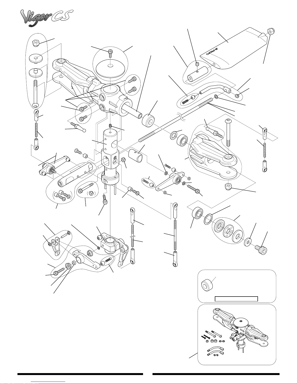
84
Main Rotor Head/Washout Assembly
™
JRP960178B
(Optional)
JRP970069
JRP960195
JRP980013
JRP970098
JRP994005
JRP980052
JRP960258
JRP980013
JRP996027
JRP960189
JRP960180
JRP980001
JRP980039
JRP970001
JRP980004
JRP994008
JRP970001
JRP960288
(Hardness #50)
JRP994007
JRP970115
JRP996026
JRP960176
JRP996020 (Red)
KS330 (Grey)
JRP994005
JRP980040
JRP960179
JRP980004
JRP970175
JRP993001 (610mm)
JRP983081 (450mm)
JRP970098
JRP980052
JRP970010
JRP981015
JRP960249
JRP980016
JRP981031
JRP970119
JRP996028
JRP970082
JRP970077
JRP980015
JRP996039
JRP970029
JRP970002
JRP980030
JRP970004
JRP980053
JRP980042
JRP970004
JRP980037
JRP981026
JRP970082
JRP980016
JRP980075
(5mm)
JRP970099
JRP981027
JRP970093
JRP980074
Blade Dampner Rubber
JRP960573: Hardness # 45
OPTION
JRP996021
Page 85

85
VIGOR™CS MANUAL PARTS LISTINGS
Main Rotor Head/ Washout Assembly
Part # Description Quantity Comments/ Additional Contents
980013 Socket Head Bolt, 3 x 8 mm 10
980004 Set Screw, 4 x 4 mm 10
996020 Flybar Paddles, Red 1
994008 Flybar Weights 2 Complete w/set screws
960189 Head Button 1 Complete w/one 3 x 8 mm socket head bolts
960180 Blade Spindle Shaft 1 Complete w/two 5 x 10 mm socket head bolts
980040 Nylon Lock Nut, 4 mm 10
960179 Flybar Control Arm 2 Complete w/steel joint ball and screws
960288 Blade Dampeners, 50 2
960195 Main Rotor Body 1 Complete w/four 3 x 8 mm socket head bolts
970098 Universal Ball Link (short) 10
994005 Control Ball, 14 mm 2
960176 Blade Holder Spacer 2
980001 Set Screw, 3 x 4 mm 10
980052 Control Rod, 2.3 x 15 mm 2
960258 Seesaw Mixing Arm Assm. w/BB 1 Complete w/all hardware
960178B Seesaw Mixing Arm w/BB (23) (optional) 2 Hardware not included
980039 Nylon Lock Nut, 3 mm Low Profile 10
994007 Spindle Shaft Guide 1
970115 Washer, .03 x 4.5 x 0.7 10
996026 Main Blade Holder 2 Complete w/two 14 mm control balls
970082 Washer, .03 x 4.5 x 0.4 10
980037 Hex nut, 2 mm 10
980030 Button Head Bolt, 3 x 5 mm 10
970069 Blade Bolts w/Spacers 2 Complete w/two 4 mm bolts, and 12 mm grip spacers
980075 Nylon Lock Nut. 5mm 10
980016 Socket Head Bolt, 3 x 15 mm 10
970029 Seesaw Spacer Collar 2
970077 Main Rotor Shaft Bolt, 3 x 22 mm 2 Complete w/two lock nuts and washers
996028 Seesaw Shaft Assembly 1 Complete w/all hardware
970010 Washout Link 2 Complete w/all hardware
981015 CA Stopper Ring 10
960013 Washout Base 1
970004 Universal Ball Link 10
980053 Control Rod, 2.3 x 50 mm 2
980042 Control Rod, 2.3 x 30 mm 2
981026 Bearing, 8 x 16 x 5 mm 2
970099 Washer, 12 x 16 x 0.5 mm 2
981027 Thrust Bearing, 8 x 16 x 5 mm 2
970093 Spindle Shaft Washer 2
980074 Socket Head Bolt, 5 x 10 mm 10
960573 Blade Dampeners, 45 2
996021 Main Rotor Head Assembly, Complete 1 Preassembled w/all hardware
960249 Washout Arm w/BB 1 Complete w/all hardware
980016 Socket Head Bolt, 3 x 15 mm 10
981031 Bearing w/Flange, 3 x 8 x 4 mm 2
970119 Spacer, 3 x 5 x 1.8 mm 2
996012 Main Rotor Shaft 1
KSJ330 Flybar Paddles, Grey 1
Page 86
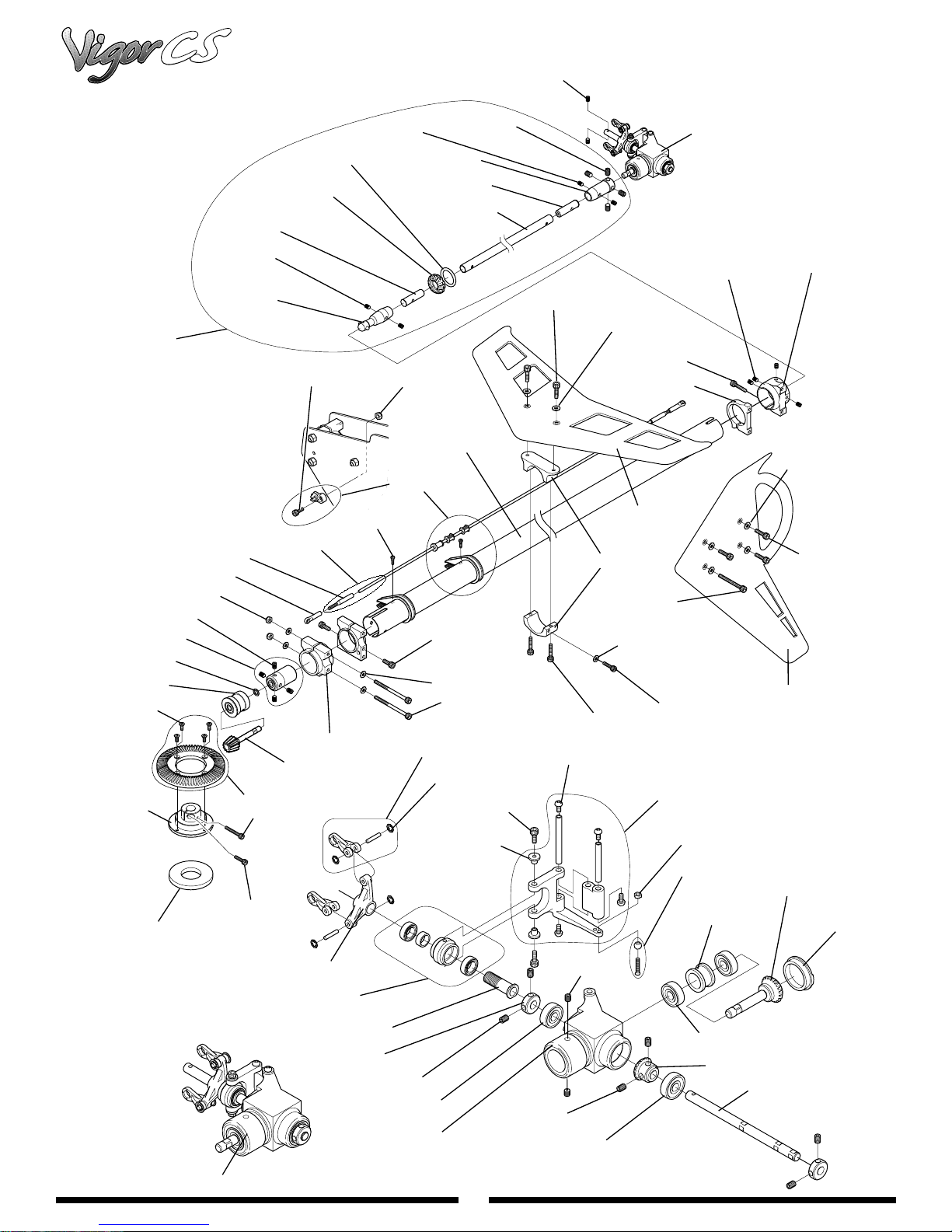
86
TAIL DRIVE SYSTEM/SHAFT DRIVE PARTS
™
JRP980067
JRP993007
JRP960094
JRP970111
JRP991002
JRP980065
JRP996035
JRP970004
JRP980039
JRP980069
JRP970171
JRP980001
JRP970169
JRP970081
JRP960092
JRP960111
JRP980060
JRP970173
JRP970172
JRP980013
JRP983007
JRP994010
JRP980001
JRP980039
JRP996024
JRP980024
JRP980004
JRP970170
JRP970171
JRP993004
JRP993005
JRP990053
JRP980036
JRP980022
JRP960056
JRP981015
JRP980073
JRP980012
JRP960132
JRP980015
JRP980036
JRP99203H
JRP980019
JRP980077
JRP980015
JRP960134
JRP980036
JRP980013
JRP996036
JRP996034
JRP980067
JRP960133
JRP980036
JRP980013
JRP99203V
JRP980015
JRP994001S
JRP994022
JRP970060
JRP994013
JRP996034
JRP994012
JRP980067
JRP981004
JRP996037
JRP970061
JRP980067
JRP991004
JRP980067
JRP980037
JRP970001
JRP994016
JRP981004
JRP994015
JRP994014
JRP994017
JRP994011
Page 87

87
VIGOR™CS MANUAL PARTS LISTINGS
Tail Drive System/Shaft Drive Parts
Part # Description Quantity Comments/ Additional Contents
JRP960056 Tail Pitch Link 2
JRP960092 Bevel Front Pinion Gear (metal) 1
JRP960094 Tube Drive Joint, Front 1
JRP960111 Bevel Tail Drive Gear (Plastic) 1 Complete with screws
JRP960132 Aluminum Tail Support Clamp 1
JRP960133 Tail Gear Box Clamp A 1
JRP960134 Tail Gear Box Clamp B 1
JRP970001 Joint Balls w/8 mm Screws 10
JRP970004 Joint Balls w/10 mm Screws 10
JRP970060 Tail Pitch Slider Assembly 1
JRP970061 Tail Control Arm Collar 1
JRP970081 Control Rod Ends 2
JRP970111 Washer, 8 x 9 x 1 mm 2
JRP970169 Shaft Drive Universal, Front 1
JRP970170 Shaft Drive Joint, Rear 1
JRP970171 Shaft Drive Tube Inserts 2
JRP970172 Shaft Drive Guides w/Bearings 2
JRP970173 Shaft Drive Guide O-Rings 2
JRP980001 Set Screws, 3 x 4 mm 10
JRP980004 Set Screws, 4 x 4 mm 10
JRP980012 Socket Head Bolts, 3 x 6 mm 10
JRP980013 Socket Head Bolts, 3 x 8 mm 10
JRP980015 Socket Head Bolts, 3 x 12 mm 10
JRP980019 Socket Head Bolts, 3 x 22 mm 10
JRP980022 Socket Head Bolts, 3 x 40 mm 10
JRP980024 Self Tapping Screws, 2 x 8 mm 10
JRP980036 Plate Washer, 3 mm 10
JRP980037 Hex Nuts, 2 mm 10
JRP980039 Nylon Lock Nuts, 3 mm 10
JRP980060 Socket Head Bolts, 3 x 2 0mm 10
JRP980065 Flat Head Bolts, 3 x 6 mm 10
JRP980067 Set Screws, 3 x 3 mm 10
JRP980069 Set Screws, 4 x 6 mm 10
JRP980073 Socket Head Bolts, 2 x 6 mm 10
JRP980077 Self Tapping Screws, 2 x 4 mm 10
JRP981004 Ball Bearing, 5 x 13 x 4 mm 2
JRP981015 CA Stopper Ring, 2 mm 10
JRP983007 CF Tail Control Rod 1 Compete with rod ends and links
JRP990053 Socket Head Bolts, 3.5 x 6 mm 2
JRP991002 Front Pinion Case w/ Bearings 1
JRP993004 Tail Drive Shaft, Aluminum 1
JRP993005 Tail Boom, Aluminum 1
JRP993006 Tail Brace Set (Black) 1 Complete with all hardware
JRP993007 Tail Drive Shaft Assm. Complete 1 Complete with all hardware
JRP994010 Tail Boom Mounting Clamp B 1
JRP994011 Tail Output Shaft 1
JRP994012 Tail Slide Ring Sleeve 1
JRP994013 Tail Output Shaft Collar 2
JRP994014 Tail Case Input Gear w/ Shaft 1
JRP994015 Tail Case Output Gear 1
JRP994016 Tail Case Input Gear Collar 1
JRP994017 Tail Case Rear Cap 1
JRP994022 Tail Pitch Plate 1
JRP996024 Tail Guide Clamp Set 1 One Compete set with screws
JRP996034 Tail Gear Box Assm. Complete 1
JRP996035 Split Gear Hub Adapter 1
JRP996037 Tail Gear Case Set 1
JRP996036 Tail Case Control Lever 1
JRP99203H CF Tail Fin, Horizontal 1
JRP99203V CF Tail Fin, Vertical 1
JRP994001S Special Washer 16 x 10 mm 1
Page 88
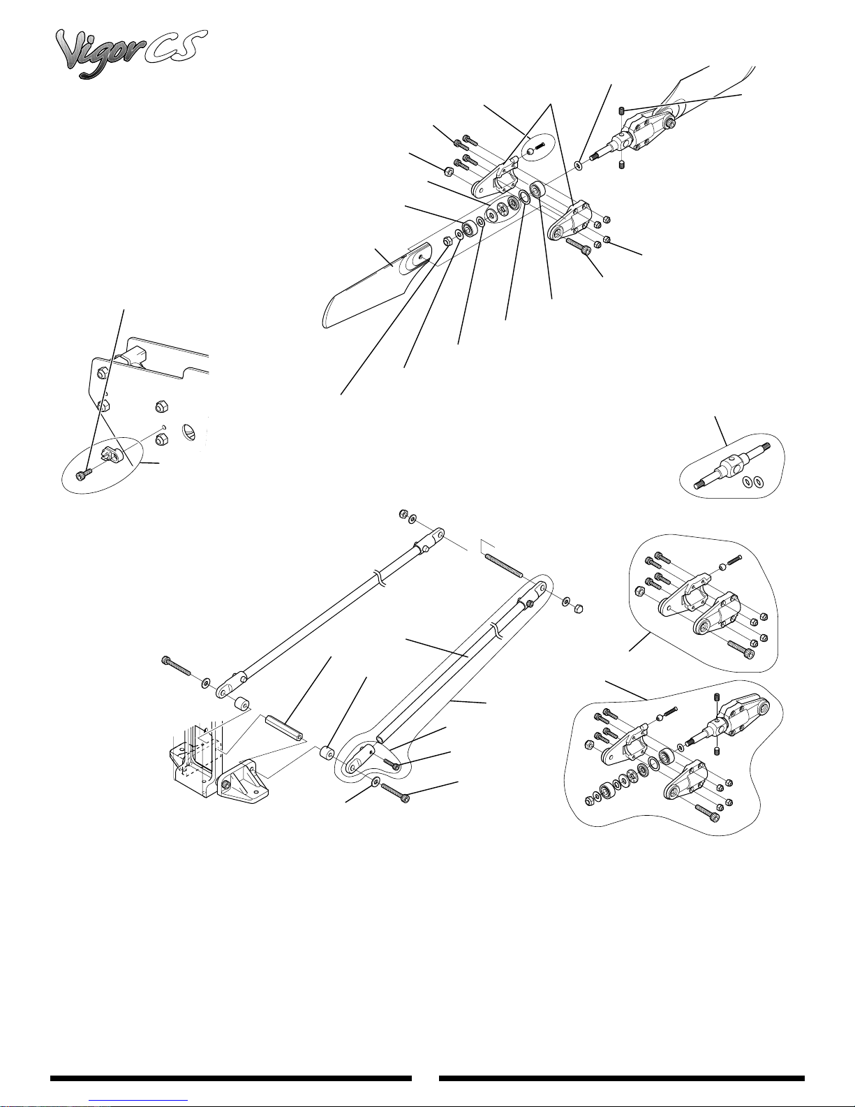
88
TAIL ROTOR BLADE HOLDER/TAIL BRACE
JRP980131
JRP980070
JRP960129
JRP980070
JRP980036
JRP981018
JRP970054
JRP970065
JRP981019
JRP976103
JRP970002
JRP981034
JRP980067
JRP980128
JRP980016
JRP960128
JRP960507
JRP960370
JRP960470
JRP993003
JRP980009
JRP994004
JRP970018
JRP970020
JRP980019
JRP980036
JRP990054
JRP996024
JRP960047
™
Page 89

89
VIGOR™CS MANUAL PARTS LISTINGS
Tail Brace/ Tail Boom Assembly
Part # Description Quantity Comments/ Additional Contents
994004 Tail Brace Connector 1 Complete w/bolt
960047 Tail Brace Tube 2
996024 Tail Rod Guide Set 5 Complete w/all hardware
970020 Main Frame Standoff , 32 mm 2
980009 Socket Head Bolt, 2.6 x 12 mm 10
980036 Flat Washer, 3 mm 10
980070 Nylon Lock Nut, 3 mm 10
993003 Tail Brace Set 1 Two brace tubes, 4 brace connectors and hardware
970002 Steel Joint Ball w/ 2 x 10 mm Screw 10 Complete w/ten 2 x 8 mm screws
960128 Tail Blade Holder Set 1 One complete set (4 pcs)
976103 O-Ring, Tail Hub 2
980131 Socket Head Bolt, 2 x 10 mm 10
981034 Thrust Bearing, 4 x 9 x 4 mm 2
981018 Open Bearing, 4 x 10 x 4 mm 2
960129 Tail Rotor Blades 2
970054 Washer, 4 x 7 x 0.5 mm 2
970065 Washer, 7 x 10 x 1 mm 2
981019 Sealed Bearing, 4 x 10 x 4 mm 2
980128 Nylon Lock Nut, 2 mm 10
980067 Set Screw, 3 x 3 mm 0
970018 Mixing Lever Spacer 2
960470 Tail Rotor Hub Assembly, Complete 1 Complete assembly
960507 Tail Blade Holder Set w/Hardware 1 One complete set (4 pcs) with hardware
960370 Tail Center Hub w/O-rings 1 Complete w/two O-rings
Page 90
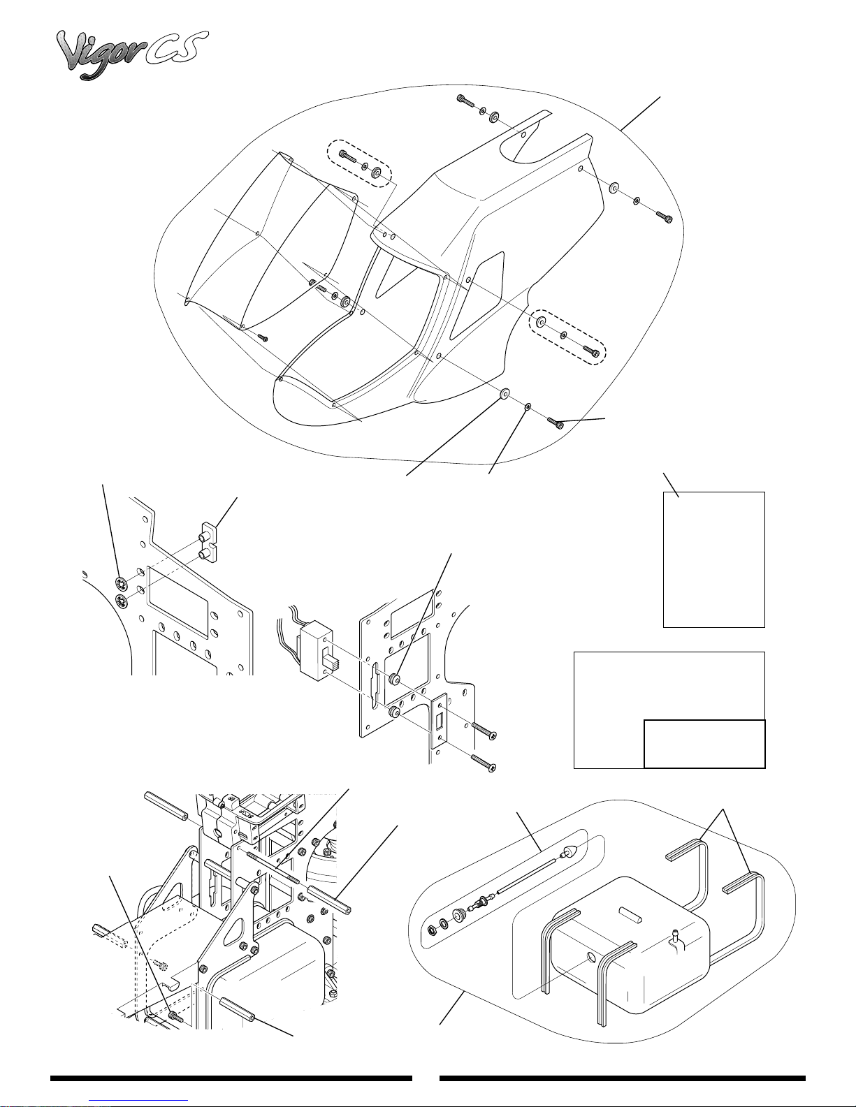
90
BODY SET/FUEL TANK ASSEMBLY
™
JRP9920011
JRP980015
JRP980132
JRP980013
JRP970104
JRP990051
JRP960072
JRP994006
JRP980036
JRP970025
JRP970106
JRP996032
Decal
Vigor CS Decal
JRP9960291
Assembly
Manual
JRP996029
JRP960336
JRP970214
JRP996010
Page 91

91
VIGOR™CS MANUAL PARTS LISTINGS
Body Set/ Fuel Tank Assembly
Part # Description Quantity Comments/ Additional Contents
9920011 Vigor Body Set 1
960072 Rubber Body Grommets 4
980036 Flat Washer, 3 mm 10
980015 Socket Head Bolt, 3 x 12 mm 10
980132 CA Stopper Ring, 3.5 mm 10
970104 Servo Mounting Plates, Type B 10
970025 Switch Mounting Grommets 4
990051 Threaded Rod, 3 x 50 mm 2
994006 Main Frame Standoff, 41 mm 2
980013 Socket Head Bolt, 3 x 8 mm 10
970214 Main Frame Standoff, 21 mm 2
970106 Fuel Tank Hardware Set 1 Complete with stopper, clunk, nut, and washer
996010 Vigor Fuel Tank Set 1 Complete with all tank hardware
960336 Tank Mounting Rubber (3 ft) 1
996032 Vigor CS Instruction Manual 1
996029 Vigor Decal Set 1
9960291 Vigor CS Decal Set 1
Page 92

Distributed exclusively by
Horizon Hobby, Inc.
4105 Fieldstone Road
Champaign, IL 61822
www.horizonhobby.com
www.vigorpilot.com
© 2001 Horizon Hobby, Inc. All Rights Reserved.
JRP9051.46
®
 Loading...