


IRIS-IMSV DRIVER
USER MANUAL
Version:V5.03

Safety Precautions and Warnings!
CAUTION! WARNING!
Pay attention to these
They indicate danger to human body or damage to the device. Before installing and putting the device into
operation, please read the safety precautions and warnings following this page.
1. Make sure that the warning signs are kept in a legible condition and replace missing or damaged signs.
2. Before starting, familiarize yourself with the operation of the inverter. It may be too late if you start
working with the inverter before read this instruction manual.
3. Never permit unqualified personnel to operate the inverter.
!
WARNING!
z This inverter produces dangerous electrical voltages and controls rotating mechanical parts.
z Death, severe injury or substantial damage to property can occur if the instructions in this operating
manual are not completed with.
z Only personnel with appropriate qualifications should work with this inverter. These personnel must be
familiar with all the warning signs and precautions laid out in these operating instructions for the
transport, installation and operation of this device.
z The successful and safe use of this inverter depends on the correct installation, commissioning,
operation and maintenance of the device.
z This device operates at high voltages.
!
CAUTION, WARNING, and
!
signals on the device or instruction documents.
!
CAUTION!
z The DC-link capacitors remain charged to dangerous voltages even the power is removed. For this
reason it is not permissible to open the inverter cover until five (5) minutes after the power has been
turned off.
z When handling the open inverter it should be noted that live parts are exposed. Do not touch these live
parts.
z The terminals R, S, T, U, V, W, P, N, B, PR, and BR can carry dangerous voltages even if the motor is
inoperative.
z Only qualified personnel may connect, start the system up and repair faults. These personnel must be
thoroughly acquainted with all the warnings and operating procedures contained with this manual.
z Certain parameter settings may cause the device to start up automatically after power on or power
recover.
DEFINITIONS
z Qualified Person
For the purposes of this manual and product labels, a qualified person is one who is familiar with the
installation, construction, operation and maintenance of this device and with hazards involved. In
addition, the person must be:
Trained and authorized to energize, de-energize, clear, ground and tag circuits and equipment in
accordance with established safety practices.
Trained in the proper care and use of protective equipment in accordance with established safety
practices.
1
www.jps.com.tw

Trained in rendering first aid.
z DANGER
For the purposes of this manual and product labels, DANGER indicates that loss of life, severe personal
injury or substantial property damage WILL result if proper precautions are not taken.
z WARNING
For the purposes of this manual and product labels, WARNING indicates that loss of life, severe personal
injury or substantial property damage CAN result if proper precautions are not taken.
z CAUTION
For the purpose of this manual and product labels, CAUTION indicates that minor personal injury or
property damage CAN result if proper precautions are not taken.
z NOTE
For the purpose of this manual and product labels, NOTES merely call attention to information that is
especially significant in understanding and operating the inverter.
!
DANGER and WARNING
z Make sure that the location selected for installation is safe, protected from moisture and splash and
drip-proof!
z Children and the general public must be prevented from accessing or approaching the equipment!
z The equipment may only be used for the purpose specified by the manufacturer. Unauthorized
modifications and the use of spare parts and accessories that are not sold or recommended by the
manufacturer of the equipment can cause fires, electric shocks and injuries.
z Keep these operating instructions within easy reach and give them to all users!
!
WARNING
This is a Class A product. In a domestic environment this product may cause radio interference in which case
the user may be required to take adequate measures.
2
www.jps.com.tw

Contents
1.Production Introduction...................................................................................................................... 7
1.1 Check Items...................................................................................................................................................................... 7
1.2 Description of Nameplate Content ............................................................................................................................. 7
1.2.1 The Label on the Packing Case ............................................................................................................................. 7
1.2.2 The Driver Rating Label.......................................................................................................................................... 8
1.3The Specification of IRIS Series ..................................................................................................................................... 9
1.3.1The Rating .................................................................................................................................................................. 9
1.3.2 The Specification of Hardware............................................................................................................................ 10
2.Condition of Storage Environment .................................................................................................11
3.Attention of Installation.....................................................................................................................11
4.Outline Dimension ..............................................................................................................................12
5.Description of Wiring..........................................................................................................................13
5.1Power Terminal ..............................................................................................................................................................13
5.1.1The Power Input Terminals (R, S, T) .................................................................................................................... 13
5.1.2The Output Terminals (U, V, W to Motor) .......................................................................................................... 13
5.2The Control Signal Terminals ......................................................................................................................................13
5.3 Brake Resistor Terminals .............................................................................................................................................14
5.4 The Input Reactor.......................................................................................................................................................... 15
5.5The Proper Screw Drive for Power Terminals........................................................................................................... 16
6.Basic Wiring Diagram for IRIS Series Drive.....................................................................................17
7. I/O Interface.........................................................................................................................................18
7.1The Map of I/O Terminal Position...............................................................................................................................18
7.1.1【0.5~2HP】Input/Output terminal on front side: ......................................................................................18
7.1.2【0.5~2HP】 Input/Output terminal on back side:..................................................................................... 19
7.1.3【3~30HP】Input/Output terminal on front side: ....................................................................................... 20
7.1.4 Definition of control signals ................................................................................................................................ 20
7.2 CON6 Comm., DI/O, AI, AM, PG_in, PG_out, XY_in Description.......................................................................... 21
7.3 XY Signal Input Description........................................................................................................................................ 23
8.Quick Start ............................................................................................................................................24
8.1Run Command Set from Digital Input Terminals ....................................................................................................24
Step II Start to Run....................................................................................................................................................... 24
8.2 RUN Command Set from Control Panel....................................................................................................................25
8.2.1 R-Panel operation method: ..............................................................................................................................25
8.2.2 C-Panel operation method:.............................................................................................................................. 25
8.3 Change the Definition of Motor’s Direction ......................................................................................................... 25
9.Parameter Description .......................................................................................................................26
9.1 IRIS-IMSV Parameter List .............................................................................................................................................26
9.2 Monitor Type Parameters’ Address........................................................................................................................32
www.jps.com.tw
3

9.3Parameter’s Type ........................................................................................................................................................32
10. IRIS-IMSV Parameter Description .................................................................................................33
10.1 Driver Specification Group........................................................................................................................................ 33
10.2 Digital Input Group .................................................................................................................................................... 35
10.3 Digital Output Group................................................................................................................................................. 36
10.4 Analog Input Group ................................................................................................................................................... 37
10.4.1 Analog Input:AI1...............................................................................................................................................37
10.4.2 Analog Input:AI2...............................................................................................................................................38
10.5 Analog Output Group................................................................................................................................................ 41
10.6 Encoder Sensor Group............................................................................................................................................... 44
10.7 IMSV Motor Group...................................................................................................................................................... 45
10.8 IMSV Control Group.................................................................................................................................................... 46
10.9 IMSV Multi-Speed Setting Group ............................................................................................................................ 52
10.10 IMSV Acc/Dec/S-curve Group................................................................................................................................. 53
10.11 DC-BUS Adjust Group .............................................................................................................................................. 56
10.12 Thermistor Adjust Group ........................................................................................................................................ 56
10.13 FAN Adjust Group..................................................................................................................................................... 57
11. Digital Input Function.....................................................................................................................58
12. Digital Output Function..................................................................................................................63
13. Flip-Flop Function Description......................................................................................................65
13.1 Pulse-Couter Group.................................................................................................................................................... 65
13.1.1 Pulse-Counter Parameters................................................................................................................................. 65
13.1.2 Pulse-Counter Digital Input...............................................................................................................................65
13.1.3 Pulse-Counter Digital Output ........................................................................................................................... 65
13.2 FlipFlop Group............................................................................................................................................................. 66
13.2.1 FlipFlop Group Parameters ...............................................................................................................................66
13.2.2 FlipFlop Group Digital-Input.............................................................................................................................66
13.2.3 FlipFlop Group Digital-Output..........................................................................................................................66
13.2.4 General Flip-Flop ................................................................................................................................................. 67
13.2.5 D-Type Flip-Flop ..................................................................................................................................................68
13.2.6 T-Type Flip-Flop................................................................................................................................................... 69
13.3 Timer Group................................................................................................................................................................. 70
13.3.1 Timer Group Parameters.................................................................................................................................... 70
13.3.2 Timer Group Digital-Input................................................................................................................................. 70
13.3.3 Timer Group Digital-Output.............................................................................................................................. 70
13.3.4 Timer Function (Delay Off Mode)..................................................................................................................... 71
13.3.5 Timer Function (Delay On Mode)..................................................................................................................... 71
13.3.6 Timer Function (Auto On/Off Mode) ...............................................................................................................72
13.4 Speed Compare Group .............................................................................................................................................. 73
13.4.1 Speed Compare Group Parameters.................................................................................................................73
13.4.2 Speed Compare Group Digital-Input ..............................................................................................................73
www.jps.com.tw
4

13.4.3 Speed Compare Group Digital-Ouput.............................................................................................................73
13.5 Speed Up / Down Counter........................................................................................................................................ 74
13.5.1 Speed Up/Down Counter Parameters............................................................................................................. 74
13.5.2 Speed Up/Down Counter Digital-Input.......................................................................................................... 76
13.5.3 Speed Up/Down Counter Digital-Ouput ........................................................................................................76
13.5.4 PulseType-Speed Up/Down Counter ..............................................................................................................77
13.5.5 Level Type-Speed Up/Down Counter.............................................................................................................. 78
13.6 Rotary Switch Group ..................................................................................................................................................79
13.6.1 Rotary Switch Group Parameters.....................................................................................................................79
13.6.2 Rotary Switch Group Digital-Input ..................................................................................................................79
13.6.3 Rotary Switch Group Digital-Output............................................................................................................... 80
13.7 PID Function ................................................................................................................................................................81
13.7.1 PID Function Parameters................................................................................................................................... 81
13.7.2 PID Function Digital-Input................................................................................................................................. 83
13.7.3 PID Function Digital-Output .............................................................................................................................83
13.7.4 PID Function Block ..............................................................................................................................................83
14. PCMD Mode.......................................................................................................................................84
14.1 PCMD Rule.................................................................................................................................................................... 84
14.2 PCMD Connection....................................................................................................................................................... 84
14.3 PCMD Function Block................................................................................................................................................. 85
14.4 PCMD Function Group............................................................................................................................................... 86
14.4.1 PCMD Group Parameters................................................................................................................................... 86
14.4.2 PCMD Group Digital Input.................................................................................................................................88
14.4.3 PCMD Group Digital Output.............................................................................................................................. 88
14.5 PCMD Function Basic Example ................................................................................................................................ 89
14.5.1 PCMD Parameter Setting................................................................................................................................... 89
14.5.2 PCMD Start............................................................................................................................................................ 89
15. Alarm Message and Maintenance ................................................................................................90
15.1 Display of Alarm Message.........................................................................................................................................90
15.2 Maintenance of Alarm Message ..............................................................................................................................90
16. CE Certificate.....................................................................................................................................94
16.1 EMC Certificate............................................................................................................................................................ 94
16.2 LVD Certificate............................................................................................................................................................. 95
17. Control Panel Description ..............................................................................................................96
17.1 C-Panel Operational................................................................................................................................................... 96
17.1.1 Lock and unlock...................................................................................................................................................96
17.1.2 Change mode....................................................................................................................................................... 96
17.1.3 Monitor mode ......................................................................................................................................................96
17.1.4 Use the fly wheel function in the monitor mode..........................................................................................97
17.1.5 Parameter mode (select, read, edit, write)..................................................................................................... 98
17.1.6 RESET Function ....................................................................................................................................................99
www.jps.com.tw
5

17.2 R-PANEL Operational ...............................................................................................................................................100
17.2.1 Control Mode 【CTL MODE】 ........................................................................................................................100
17.2.2 Monitor Mode 【MON MODE】 ....................................................................................................................100
17.2.3 Parameter Editing Mode 【PAR MODE】....................................................................................................101
17.2.4 ALARM MODE【ALM MODE】........................................................................................................................101
17.2.5 RD / WT【Single-Word】/【Double-Word】Parameters .........................................................................102
17.2.6 Single-Word】/【Double-Word】Negative Numbers...............................................................................103
17.2.7 Alarm Mode of R-Panel【ALM Code Description】 ...................................................................................104
17.2.8【Definition of Cables】 ...................................................................................................................................104
www.jps.com.tw
6

1.Production Introduction
R
1.1 Check Items
To avoid the carelessness during packing and delivery, please check the list below carefully。
Items Amount Contents
IRIS IMSV Manual 1 book Please read carefully and keep with care for referring usage.
Check the spec. of the device with the case label is same or not.
IRIS IMSV Driver 1 set
Encoder
Feedback cable
If any miss or defect happened, please contact with the agency to get resolve of the problem.
1 set
1.2 Description of Nameplate Content
1.2.1 The Label on the Packing Case
Check the out looking of the device to make sure that there is no defect on it.
All screws should be tighten and exist.
Make sure content in the package(cable had been tested before packing)。
※Attached only when driver rated current higher than 11A
2R5-IMSV-PCMD-A-
220V
The contents of indication:
1. 2R5 Æ Indicates that this driver should access 220 Volt power and the rated output is 5A.
2. IMSV Æ Suit for Induction motor with encoder feedback.
3. PCMD Æ Stndard type. Pulse Command Mode embedded.
4. A Æ Indicates that this driver is an Advanced type.
5. R Æ Indicates that the control panel of this driver .
Description of Control Panel
C
C-Panel
R
6. 220V Æ Indicate the suitable power rating individually.
R-Panel
7
www.jps.com.tw
1.2.2 The Driver Rating Label
The figure below is a sample of the rating label that is put on the outside of the driver.
MODEL 2R5-IMSV-PCMD-A-C
INPUT
OUPUT
Serial NO
The contents of rating label are showed below:
MODEL:2 R □ - IMSV- STD - A- R
AC 3ψ 220V / 50/60HZ
3ψ 5A/ 2KVA/ 0~400HZ
080A0001
MADE IN TAIWAN
Input voltage
Model series R : IRIS Series
Output current According to Driver-Current
Suit motor IMSV : Induction Motor Type
Firmware Standard
Function Factory Only
2 : 220VAC
4 : 380VAC
INPUT :AC3Ø220 / 50/60HZ
OUTPUT : 3Ø5A 2KVA / 0~400Hz
Panel R Panel
Power-Type A.C. 1 or 3 Phase, 220Volt.
Power Frequency 50Hz/60Hz
Phase / Current 3Phase/5A
Capacitance (KVA) 2KVA
Output Frequency Range 0 ~ 400HZ
www.jps.com.tw
8

1.3The Specification of IRIS Series
1.3.1The Rating
220V Series:
2R□ 2 3P5 5 7 11 17 24 33 46 61 90
Output Current 2 3.5 5 7 11 17 24 33 46 61 90
Horse Power(HP) 0.5 1 1.5 2 3 5 7.5 10 15 20 30
Rated Capacity(KVA) 0.65 1.3 1.8 2.5 4.0 6.5 9.5 13 19 25 34
Rated Power(KW) 0.4 0.75 1 1.5 2.2 3.7 5.5 7.5 11 15 22.5
Max Output Voltage(V) Match 3 phase Input Voltage
Dimension P1 P2 P3 P4
380V Series:
4R□ 5P5 8P5 12 17 23 31 45
Output Current(A) 5.5 8.5 12 17 23 31 45
Horse Power(HP) 3 5 7.5 10 15 20 30
Rated Capacity(KVA) 4.0 6.5 9.5 13 19 25 34
Rated Power(KW) 2.2 3.7 5.5 7.5 11 15 22.5
Max Output Voltage(V) Match 3 phase Input Voltage
Dimension P2 P3 P4
www.jps.com.tw
9

1.3.2 The Specification of Hardware
2R◇- IMSV- STD - □
□Driver type
Digital Input 6 Unit
<=2HP 1 Unit
Digital Output(Signal)
>2HP 2 Unit
<=2HP Without
Digital Output (Relay)
>2HP 1 Unit
Analog Input 2 Unit(12bit resolution)
Analog Output 1 Unit
RS485 Communication Interface 2 Units
Fan Malfunction & Precaution Function Included
Over Heat Protect Function Included
PG Feedback Interface 1Unit
Brake Discharge MOS-FET Included
External Received Interface 1 Unit
A Type
www.jps.com.tw
10

2.Condition of Storage Environment
This driver should be contained in the packing case. If do not use this driver temporarily, in order to ensure
this driver in our warranty scope, please follow the items below:
z The ambient temperature must be in the scope of - 20℃ to +65℃, relative humidity 0% to 95%, and no
dew clings.
z Must be preserved in the environment that is dustless, stainless, and dry.
z Avoid to store under the environment that has caustic gas or liquid.
3.Attention of Installation
!
WARNING
To guarantee the safe operation of the equipment it must be installed and commissioned properly by
qualified personnel in compliance with warnings laid down in these operating instructions.
Take particular note of the general and regional installation and safety regulations regarding work on high
voltage regulations, as well as the relevant regulations regarding the correct use of tools and personal
protective gear.
Make sure that the unobstructed clearance for each of the cooling inlets and outlets above and below the
inverter is at least 100mm.
Make sure that a space of 40mm is kept free at the sides of the inverter to permit the cooling air to escape
from the side slits.
>10cm
Cooling Air
>4cm
>4cm
>10cm
Ensure that the temperature does not exceed the specified level when the inverter is installed in cubicle.
Avoid excessive vibration and shaking of the equipment.
Do not be obstructing the cooling fan that installed on the inverter, it is used to build proper airflow for heat
sink thermo dissipation. And do not touch the fan hole when it is running.
Please consider the possible use of options, such as RFI suppression filters at the planning stage.
!
WARNING
To prevent electrical shock, do not open cover for at least 5 minutes after removing AC power to allow
capacitors to discharge.
Cooling Air 保持
www.jps.com.tw
11

4.Outline Dimension
P1:0.5HP~2HP Unit:mm P2:3HP~5HP Unit:mm
P3:7.5 HP~10HP Unit:mm P4:15HP~30HP Unit:mm
www.jps.com.tw
12

5.Description of Wiring
The upper cover must be removed in order to connect the electrical leads.
5.1Power Terminal
The power terminals are divided into three portions:
1.
The power input terminals (R, S, T) receives power for the operation of the inverter.
2.
The output terminals (U, V, and W) deliver output power to motor.
3.
Brake resistor should be connects to icon
!
NOTE: The terminal has icon should be connected to Earth properly.
!
WARNING: Never connect power source line to U, V, W, P, N, B terminals.
5.1.1The Power Input Terminals (R, S, T)
!
WARNING! NOTE!
z The power input terminals are R, S, and T. Never connect power source line to U, V, W, P, N, B terminals.
z Between the power source and driver, add NFB for system protection.
z There are static sensitive components inside the Printed Circuit Board. Avoid touching the boards or
components with your hands or metal objects.
z Make sure to connect the power terminals tight and correctly.
z Make sure that the power source supplies the correct voltage and is designed for the necessary current.
.
z The terminal has icon should be connected to Earth properly.
5.1.2The Output Terminals (U, V, W to Motor)
z Make sure the motor’s rated voltage and current are suitable with driver’s specification.
!
WARNING: Do not insert contactors between driver and motor; the U, V, W terminals should be connected
to motor directly.
5.2The Control Signal Terminals
!
WARNING! NOTE!
All the input/output control signal lines, or remote panel lines and communication lines must be laid
separately from the high current power/motor/brake lines. They must not be fed through the same cable
conduit/trucking.
www.jps.com.tw
13

5.3 Brake Resistor Terminals
!
NOTE: This driver contains braking discharge circuits. The terminals have icon
connect external resistor to discharge the re-generating energy when in braking condition.
Refer to the list below when choosing resistor for braking discharge. The wattage of resistor can be increased
for heavier re-generating energy or higher discharge duty.
Model Resistance(ohm) Wattage (W)
2R2 400 40
2R3P5 300 60
2R5 200 80
2R7 100 150
2R11 60 250
2R17 40 300
2R24 30 500
2R33 20 600
2R46 15 1000
are used to
2R61 10 1500
2R90 10 2000
4R5P5 250 250
4R8P5 150 300
4R12 100 500
4R17 75 750
4R23 50 1000
4R31 40 1500
4R45 40 2000
The discharge duty is 10 %
www.jps.com.tw
14

5.4 The Input Reactor
When power supply capacity is larger than 500KVA and /or using thyrister, phase advance capacitor etc. from
same power supply, must fit an A.C.L. in front of R.S.T. power input to curb instantaneous current and to
improve power efficient ratio. Refer to the list below to choose proper reactance.
Voltage (V) Model Current (A) Inductance
2R2 6 1.8mH
2R3P5 6 1.8mH
2R5 6 1.8mH
2R7 10 1.1mH
2R11 11 0.71mH
220
380
2R17 17 0.53mH
2R24 24 0.35mH
2R33 33 0.26mH
2R46 46 0.18mH
2R61 61 0.13mH
2R90 120 0.09mH
4R5P5 7.5 3.6mH
4R8P5 10 2.2mH
4R12 15 1.42mH
4R17 20 1.0mH
4R23 30 0.7mH
4R31 40 0.53mH
4R45 60 0.36mH
www.jps.com.tw
15

5.5The Proper Screw Drive for Power Terminals
It is necessary to choose proper tool for wiring connection to avoid screw stripped or burst. Please refer to the
list below to choose a proper screw drive for driving power terminals.
A - B mm C mm D mm P mm L mm
0.6 - 3.3 3.3 - - -
B C mm D mm P mm L mm
#0 3.3 - - -
www.jps.com.tw
16

6.Basic Wiring Diagram for IRIS Series Drive
POWER
SOURCE
NFB
POTENTIAL
METER
Filter
E
AI1
EMI
R
S
T
BRAKE
V5T
0V ~ +10V RANGE
-10V ~ +10V RANGE
IGBT
LCD-485
U
V
W
AM1
MOTOR
TO PLC、
HMI、、、
ACOM
485-A
485-B
DI1
DI2
DI3
DI4
FWD
REV
G24
24V
PHOTO
ISOLATED
DIGITAL
INPUT PORT
DO3
24V
OPEN
COLLECTER
G24
ACOM
RY3A
RY3B
24V
DO1
DO2
MAX. RATING
200V, 3A
www.jps.com.tw
17

7. I/O Interface
7.1The Map of I/O Terminal Position
Refer to the position map to locate the terminals or interface.
7.1.1【0.5~2HP】Input/Output terminal on front side:
DI1 DI2 DI3 DI4 DI5 DI6 DO1 DO2 DO3
TM1 TM2
AI2 AI1 5V AM1 485B 485A
ACOM 24V G24
DB1(F):XY IN
DB1(F):XY_IN DB2(M):PG_IN
XY_IN
PIN Signal
1 X+
2 X-
3 Y+
4 Y-
5
6
7 5V
8 ACOM
9 ---
FG SHIELD
---
PG_IN
1A+
2A-
3B+
4B-
5C+
6C-
7
8
9
10
11
---
DB2(M):PG IN
TM1: Terminal Spec. IEC 130V,8A
Digital Input:DI1 ~ DI6。
Digital Ouput:DO1 ~ DO3。
Voltage Ground:G24。
TM2: Terminal Spec. IEC 130V,8A
Voltage Output:4V。
Analog Output:AM1。
Analog Input:AI1、A I2。
Voltage Outp ut:T5V、(ACOM)。
RS485 Communication(485-A,485-B)。
12
13 V5
14
PGND
15
FG SHIELD
www.jps.com.tw
18

7.1.2【0.5~2HP】 Input/Output terminal on back side:
DB3(M):PG OUT
DB3(M):PG_OUT
PG_OUT
CON9 9PinD-sub(Male) Signal
*PG_OUT:use cable with DB9M-SC8P-0.5M。
*DB9M-SC 8P-0 .5M:Optional。
Pin1 Pin 1 OA+
Pin2 Pin 2 OA-
Pin3 Pin 3 OB+
Pin4 Pin 4 OB-
Pin5 Pin 5 OC+
Pin6 Pin 6 OC-
Pin 7 ---
Pin7 Pin 8 VSS-D
Pin 9 ---
Pin8 FG SHIELD
www.jps.com.tw
19

7.1.3【3~30HP】Input/Output terminal on front side:
CON9 PG1 CON8 CON6
A I 2 5 V
RY3A RY3B ACOM ACOM
485A 485B AM1 AI1 T5V ACOM 24V G24
D O1 D O2 D I 1 D I 2 D I 3 D I 4 FWD REV
7.1.4 Definition of control signals
CON9 Definition
Æ24V
PG-IN caption:
Wire name:D15M-SJW10P-0.5M
Connector defined:
PG1 D-sub15(M) definition
Pin1 Pin1 A
Pin2 Pin2 /A
Pin3 Pin3 B
Pin4 Pin4 /B
Pin5 Pin5 C
Pin6 Pin6 /C
Pin7 Pin13 +5V
Pin8 Pin14/ Pin15 0V
Pin9
Pin10
XY-IN caption:
Wire name:D09F-SC07P-0.5M
Connector defined:
CON8 D-sub9(F) definition
Pin1 Pin1 X
Pin2 Pin2 /X
Pin3 Pin3 Y
Pin4 Pin4 /Y
Pin5 N.C.
Pin6 N.C.
Pin5 Pin7 +5V
Pin6 Pin8 0V
Pin9 N.C.
Pin7 shell shield
PG-OUT caption:
Wire name:D09M-SC08P-0.5M
Connector defined:
CON6 D-sub9(M) definition
Pin1 Pin1 Aout
Pin2 Pin2 /Aout
Pin3 Pin3 Bout
Pin4 Pin4 /Bout
Pin5 Pin5 Cout
Pin6 Pin6 /Cout
Pin7 N.C.
Pin7 Pin8 0V
Pin9 N.C.
Pin8 shell shield
www.jps.com.tw
20

7.2 CON6 Comm., DI/O, AI, AM, PG_in, PG_out, XY_in Description
C
A
V
G
A
A
A
A
S
f
V
-
(x)
Terminal Name Function Hardware construction
CON6
PLC
485-A
RS485 communication port
(photo coupler isolated)
PLC
485-B
Analog output
AM1
(refer to ACOM)
AI1
Analog Input
(refer to ACOM)
AI2
5V reference voltage
T5V
(refer to ACOM)
The reference ground of Analog
ACOM
signal system.
24V 24V output power (refer to G24).
The reference ground of digital
G24
I/O system.
CC
RX
485-
485-B
PWM Waveform from CPU
I(x)
COM
!
NOTE
1.
ACOM and G24 are not the same electric level.
2.
5V is used to be a voltage reference for analog
R
ND
RE
DE
B
D
GND
Photo
coupler
12Bit Resolution Analog Input
R
C
M1
COM
To CPU
OP
signal; 24V is used for digital input / output
signal connection; do not use both these two
voltage as power supplier to external circuits.
VCC
TE
TX
VC
Digital output terminals.
DO-(x)
(reference ground is G24)
DO1 ~DO3
Only be used under 24V voltage
ignal
rom C PU
level to keep system stable.
Programmable by setting
parameter value.
Digital Output
Digital input terminals.
(reference ground is G24)
Only be used under 24V voltage
DI1 ~ DI6
level to keep system stable.
Programmable by setting
DI
G24
parameter value.
www.jps.com.tw
21
Open Collector
+24
4.7K
G24
G24
To CPU
GND
Digital Input

CON6
PG_IN
PG_OUT
XY_IN
The input hardware structure of
signal B & C is same as signal A.
The Encoder type muse be 5V
Line Driver.
Inside the IRIS drive PG_OUT
and PG_IN signal is derectly
connected.
The input hardware structure of
signal OB+-、OC+- is same as
signal OA+-.
The XY pulse input hardware
structure is design as 5V Line
Drive type input.
The input hardware structure of
signal Y is same as signal X.
220,1/4W
A+
A-
Vcc
A
A+
A-
OA+
OA-
Vcc
220,1/4W
X+
X-
X
www.jps.com.tw
22

7.3 XY Signal Input Description
5V Line Driver Type Signal +24V Open Collector Type Signal
z If use 5V Line Deiver signal as digital input ,
Just connect to terminal。
220,1/4W
X+
X-
ps:Y signal & X signal 。
Use 5V Line Driver signal,please refer to: Open Collector Signal,please refer to:
X+
Vcc
5V
0V
z If use 24V Open Collector signal as digital input ,
Need to connect limit resistance(2K,1W)。
2K,1W
+24V
X
ps:Y signal & X signal 。
X+
X-
220,1 /4W
Vcc
X-
5V
X-
0V
X
24V
0V
5V
X
5V
0V
X
0V
www.jps.com.tw
23

8.Quick Start
8.1Run Command Set from Digital Input Terminals
!
NOTE!
Please make sure the specification of motor’s feed back encoder, and check the related parameters’ setting
value. Refer to Chapter 0 10.6 Encoder Sensor Group for detailed description.
Step I Setting Basic Parameters and Auto Tuning (Close Loop)
A. Setting the Parameter of Motor
Refer to the nameplate on motor to set the following parameters:
1.
Pr.210 Full Load Current (%)
This parameter defines the percentage of the motor’s rating and the driver’s rating.
Full Load Current (%) = (Rated Current of Motor / Rated Current of Driver) x 100%
2.
Pr.116 Motor Pole No.
3.
Pr.128 Max. RPM Limit
B. Execute R&L Auto Tuning
1.
Setting Pr.003 (Motor Operation Mode) to be 7 (select R&L Auto Tuning).
2.
Reset the driver.
3.
Connect FWD and G24 terminals, and wait till display shows 【END or do】
After completing R&L Auto Tuning, driver will set following parameters automatically:
1.
Pr.216 the phase resistance of motor.
2.
Pr.217 the phase inductance of motor.
C. Execute Current Gain Auto Tuning
1.
Setting Pr.003 (Motor Operation Mode) to be 6 (select Current Gain Auto Tuning).
2.
Reset the driver.
3.
Connect FWD and G24 terminals, and wait till display shows 【END or do】
After completing Current Gain Auto Tuning, driver will set following parameters automatically.
1.
Pr.004 Current Loop P-gain
2.
Pr.005 Current Loop I-gain
D. Set Motor Operation Mode
1.
Setting Pr.003 (Motor Operation Mode) to be 2 (Close Loop Mode.)
2.
Reset the driver.
Step II Start to Run
1.
Setting Pr.120 (Speed Set 0) = 100. ÆSetting Speed Set 0 = 100 rpm.
2.
Connect FWD and G24 terminals, the motor will start and run at 100 rpm speed
www.jps.com.tw
24

8.2 RUN Command Set from Control Panel
8.2.1 R-Panel operation method:
1. Pr.120 (Speed Set 0) = 100 Î Setting Speed Set 0 = 100 rpm。
2. Directly click FWD button to operate。
8.2.2 C-Panel operation method:
1. Pr.120 (Speed Set 0) = 100 Î Setting Speed Set 0 = 100 rpm.
2. Pr.065 (FWD function select) = 0
3. Pr.068 (Virtual function select) = 73
4. Pr.059 (Panel’s Run / Stop Enable) = 1
Now, the motor can be set to run or stop directly from Panel’s run / stop keys.
Î Disable FWD terminal function.
Î Setting virtual function to be 73 (FWD function).
Î Enable the Run / Stop function.
8.3 Change the Definition of Motor’s Direction
If in regular condition, the driver can drive motor normally and want to change the direction definition of
motor. Please following the steps listed below:
※ When driver is in Forward Run condition, and the motor rotating in CCW direction (face to the motor axis):
1.
Setting Pr.065 (FWD terminal function select) to be 0 Î Disable FWD terminal functions.
2.
Turn off AC input power
3.
Connect the U, V, W wires to the terminals U, V, W of driver. Î Change the output power lines.
4.
Turn on the AC input power.
5.
Setting Pr.188 (Encoder sensor direction) to be 1. Î Phase B leads phase A.
6.
Setting Pr.065 = 73 Î Redefined the FWD terminal function.
※ When driver is in Forward Run condition, and the motor rotating in CW direction (face to the motor axis):
1.
Setting Pr.065 (FWD terminal function select) to be 0 Î Disable FWD terminal functions.
2.
Turn off AC input power
3.
Connect the U, W, V wires to the terminals U, V, W of driver. Î Change the output power lines.
4.
Turn on the AC input power.
5.
Setting Pr.188 (Encoder sensor direction) to be 0. Î Phase A leads phase B.
6.
Setting Pr.065 = 73 Î Redefined the FWD terminal function.
www.jps.com.tw
25

9.Parameter Description
9.1 IRIS-IMSV Parameter List
Driver Specification Group <Refer to Chapter-10.1> *There is different setting for different model
No. Name Default Min. Max. Unit Type GXX-XX
071 Unit Address 1 1 63 -- FR/W;R 00-00
097 Driver system software version -- 0 FFFF Version F 00-01
130 AC power input voltage *220 10 1000 Vac(rms) FR/W 00-04
209 Rated output current *5.0 1.0 6000.0 Ampere FR/W 00-05
239 Carrier frequency *10.0 2.0 16.0 Khz FR/W;R 00-06
337 Special Function *0 0 65535 -- F 00-03
348 Motor type 2 0 4 -- F 00-02
368 EAROM Lock 0 0 1 -- FR/W 00-07
369 Recover parameter to default 0 0 1 -- R/W 00-08
Digital Input Group <Refer to Chapter-10.2>
No. Name Default Min. Max. Unit Type GXX-XX
011 Status of DI1~DI16 0000 0000 FFFF -- M 01-00
059 The enable switch of panel’s Run/Stop keys 0 0 1 -- R/W 01-17
061 DI1 function select 0 0 255 -- R/W 01-01
062 DI2 function select 0 0 255 -- R/W 01-02
063 DI3 function select 0 0 255 -- R/W 01-03
064 DI4 function select 0 0 255 -- R/W 01-04
065 FWD (DI5) function select 73 0 255 -- R/W 01-05
066 REV (DI6) function select 74 0 255 -- R/W 01-06
068 The Run/Stop keys function select 0 0 255 -- R/W 01-08
475 DI15 function select (a virtual input, links to DO15) 0 0 255 -- R/W 01-15
476 DI16 function select (a virtual input, links to DO16) 0 0 255 -- R/W 01-16
【NOTE】Digital input function definition can’t be repeated. Check this point after finish setting this group.
Digital Output Group <Refer to Chapter-10.3>
No. Name Default Min. Max. Unit Type GXX-XX
012 DOx Status 0000 0000 FFFF -- M 02-00
111 DO-1 function select 0 0 255 -- R/W 02-01
112 DO-2 function select 0 0 255 -- R/W 02-02
113 DO-3 function select 0 0 255 -- R/W 02-03
165 DO-15 function select (virtual output, link to DI15) 0 0 255 -- R/W 02-15
166 DO-16 function select (virtual output, link to DI16) 0 0 255 -- R/W 02-16
Analog Input Group <Refer to Chapter-10.4>
www.jps.com.tw
26

No. Name Default Min. Max. Unit Type GXX-XX
229 AI-1 Adc data 0 0 4095 -- M 03-00
230 AI-1 Positive Maximum Reference 4095 0 4095 -- FR/W 03-01
231 AI-1 Zero(/Middle) Reference 2048 0 4095 -- FR/W 03-02
232 AI-1 Negative Minimum Reference 0 0 4095 -- FR/W 03-03
233 AI-1 TYPE 0 0 1 -- R/W;R 03-04
234 AI-1 Command Value 0.00 0.00 100.00 % M 03-05
235 AI-1 D-band Value 0 0 1000 -- R/W 03-06
477 AI-2 Adc data 0 0 4095 -- M
481 AI-2 Positive Maximum Reference 4095 0 4095 -- FR/W
482 AI-2 Zero(/Middle) Reference 2048 0 4095 -- FR/W
483 AI-2 Negative Minimum Reference 0 0 4095 -- FR/W
484 AI-2 TYPE 0 0 1 -- R/W;R
485 AI-2 Command Value 0.00 0.00 100.00 % M
486 AI-2 D-band Value 0 0 1000 -- R/W
487 AI-2 Compare Set Value 50 0.00 100.00 % R/W
488 AI-1 Compare Set Value 50 0.00 100.00 % R/W
Analog Output Group <Refer to Chapter-10.5>
No. Name Default Min. Max. Unit Type GXX-XX
370 AMOUT-Select Data 0 0 15 -- R/W;R 05-00
371 AMOUT-Full-Scale Data Range 0 0 65535 -- FR/W 05-01
372 AMOUT-Test Data( 0~100% Full scale) 0.0 0.0 100.0 % RAM 05-02
373 AMOUT-100% Full Scale adjustment 0.0 0.0 100.0 % FR/W 05-03
374 AMOUT-75% adjustment 0.0 0.0 100.0 % FR/W 05-04
375 AMOUT-50% scale adjustment 0.0 0.0 100.0 % FR/W 05-05
376 AMOUT-25% scale adjustment 0.0 0.0 100.0 % FR/W 05-06
377 AMOUT-12.5% scale adjustment 0.0 0.0 100.0 % FR/W 05-07
Encoder Sensor Group <Refer to Chapter-10.6>
No. Name Default Min. Max. Unit Type GXX-XX
188 ENCODER DIRECTION 0 0 1 -- FR/W;R 07-00
189 ENCODER PPR 256 256 60000 -- FR/W;R 07-01
190 ENCODER A/B/Z Status 0 0 7 -- M 07-04
191 ENCODER COUNTER 0 0 65535 -- M 07-05
192 ENCODER DATA FILTER BUFFER 6 0 6 FR/W;R 07-03
193 ENCODER CHECK TIME 0 0 30000 ms R/W 07-08
194 ENCODER TYPE 0 0 2 -- FR/W;R
354 Actual Counts Per Revolution 0 0 65535 Cks M
www.jps.com.tw
27

XY Pulse Tracking Group <Refer to Chapter-14.4>
No. Name Default Min. Max. Unit Type GXX-XX
396 Servo position gain 0 0 60000 Rpm/rev R/W
398 X/Y Pulse Counter 0000 0000 FFFF Cks M
399 X/Y Input DIRECTION 0 0 1 -- R/W
450 X/Y MUL1 Setting-Value(ROM) 1000 0 65535 -- R/W
451 X/Y DIV1(ROM) 1000 0 65535 -- R/W
452 X/Y Commad Type 0 0 1 -- R/W
453 X/Y Pcmd Sampling time 50 10 1000 -- R/W
454 X/Y Pcmd Feed forward Gain 0 0 100 % R/W
455 X/Y Input Status 0 0 65535 -- M
IMSV Motor Group <Refer to Chapter-10.7>
No. Name Default Min. Max. Unit Type GXX-XX
116 Motor Pole No 8 2 128 FR/W;R 10-02
198 Motor Ke(Back Emf constant) 0 0 10000 Volts/krpm
202 No-Load Speed (=Base or Synchrnous Speed) 1800 0 30000 rpm R/W
203 Full-Load SLIP-RPM 60 0 1000 rpm R/W
210 Full Load Current(?% of AMP-Rating-Current) 50 0 200 % FR/W 10-00
211 Filed Current(?% of Full-Load-Current) 30 0 200 % FR/W 10-01
215 Electronic Over-Load Thermal Relay Time 3 0 120 sec R/W 10-04
216 RESISTANCE(between V&W, U phase open) 1.000 0.00 60.00 Ohm FR/W 10-05
217 INDUCTANCE(between V&W, U phase open) 1.00 0.00 60.00 mH FR/W 10-06
IMSV Multi-Speed Setting Group <Refer to Chapter-10.9>
No. Name Default Min. Max. Unit Type GXX-XX
010 JOG Rpm 60 0 30000 rpm R/W
119 Actual RPM Set Command 0 -30000 30000 rpm M 16-10
120 Speed Set0 0 0 30000 rpm R/W 16-00
121 Speed Set1 0 0 30000 rpm R/W 16-01
122 Speed Set2 0 0 30000 rpm R/W 16-02
123 Speed Set3 0 0 30000 rpm R/W 16-03
124 Speed Set4 0 0 30000 rpm R/W 16-04
125 Speed Set5 0 0 30000 rpm R/W 16-05
126 Speed Set6 0 0 30000 rpm R/W 16-06
127 Speed Set7 0 0 30000 rpm R/W 16-07
128 Maximum RPM Limit 3000 0 30000 rpm FR/W 16-08
278 Select Speed Source when SWx=000 0 0 19 - R/W;R 16-09
www.jps.com.tw
28

IMSV Closed-loop Motor Setting Group <Refer to Chapter-10.8>
No. Name Default Min. Max. Unit Type GXX-XX
003 Drive Operation mode 11 0 29 R/W;R 15-00
004 Current loop P-gain 1000 0 3000 R/W 15-01
005 Current loop I-gain 100 0 3000 R/W 15-02
008 Current loop filter level 0 0 7 R/W 15-03
018 Speed loop P/I gain select 1 1 2 R/W 15-04
029 1'st Speed Loop Switch point 100 0 3000 rpm R/W 15-05
031 1'st speed loop P-gain 500 0 1000 R/W 15-06
032 1'st speed loop I-gain 50 0 1000 R/W 15-07
033 1'st Speed Loop Filter 0 0 7 R/W 15-08
086 Torque control mode 0 0 3 R/W 15-13
087 Torque Limit-I 100.0 0.0 300.0 % R/W 15-14
088 Torque Limit-II 100.0 0.0 300.0 % R/W 15-15
089 Torque Limit-III 100.0 0.0 300.0 % R/W 15-16
090 Torque Limit-IV 100.0 0.0 300.0 % R/W 15-17
095 Torque Compare Level (% of Motor Rated Torque) 100 0 300 % R/W 15-20
096 Random Torque Command Setting (RAM) 0.0 0.0 300.0 %
108 Torque Droop Range 10 0 100 % R/W 15-18
110 Directional Limitation 0 0 2 FR/W 15-19
160 2'nd Speed Loop Switch point 100 0 3000 rpm R/W 15-09
161 2'nd speed loop P-gain 500 0 1000 R/W 15-10
162 2'nd speed loop I-gain 50 0 1000 R/W 15-11
163 2'nd speed loop filter l 0 0 7 R/W 15-12
www.jps.com.tw
29

IMSV Acc/Dec/S-curve Group <Refer to Chapter-10.10>
No. Name Default Min. Max. Unit Type GXX-XX
053 ACC Time 5.00 0.00 650.00
054 DEC Time 5.00 0.00 650.00
Sec/Krpm
Sec/Krpm
R/W 17-00
R/W 17-01
055 Scurve T1 time 0.00 0.00 5.00 Sec R/W 17-02
056 Scurve T2 time 0.00 0.00 5.00 Sec R/W 17-03
057 Scurve T3 time 0.00 0.00 5.00 Sec R/W 17-04
058 Scurve T4 time 0.00 0.00 5.00 Sec R/W 17-05
289 START OPTION SELECT 0 0 1 R/W
290 START DELAY TIME 0.00 0.00 60.00 Sec R/W
291 BRAKE HOLD TIME 1.00 0.00 60.00 Sec R/W 17-06
Counter Group <Refer to Chapter-13.1>
No. Name Default Min. Max. Unit Type GXX-XX
240 PULSE_COUNTER-Mon1 0 0 65535 Counts M
241 PULSE_COUNTER-Mon2 0 0 65535 Counts M
242 PULSE_COUNTER-Mon3 0 0 65535 Counts M
243 PULSE_FREQUENCY-Mon1 0 0 65535 Hz M
244 PULSE_FREQUENCY-Mon2 0 0 65535 Hz M
245 PULSE_FREQUENCY-Mon3 0 0 65535 Hz M
246 COMPARE_SET-1 0 0 65000 -- R/W
247 COMPARE_SET-2 0 0 65000 -- R/W
248 COMPARE_SET-3 0 0 65000 -- R/W
Timer Group <Refer to Chapter-13.3>
No. Name Default Min. Max. Unit Type GXX-XX
249 TIMER-A, Type Select 2 0 2 R/W 62-00
250 TIMER-A, T1 Period 1.00 0.01 300.00 Sec R/W 62-01
251 TIMER-A, T2 Period 1.00 0.01 300.00 Sec R/W 62-02
252 TIMER-B, Type Select 2 0 2 R/W 62-03
253 TIMER-B, T1 Period 1.00 0.01 300.00 Sec R/W 62-04
254 TIMER-B, T2 Period 1.00 0.01 300.00 Sec R/W 62-05
Up/Down Group <Refer to Chapter-13.5>
No. Name Default Min. Max. Unit Type GXX-XX
104 Up/Dn Setting Mode 0 0 1 R/W 64-00
105 Up/Dn Data Preset Value 0 0 3000 Rpm R/W 64-01
106 Up/Dn Rate ( Trigger active ) 1.00 0.00 300.00 Rpm/Trigger R/W 64-02
107 Up/Dn Rate ( Level active ) 100 0 30000 Rpm/Sec R/W 64-03
117 Up/Dn Data Temperary Value 0 0 30000 Rpm M
www.jps.com.tw
30

Speed Compare Group <Refer to Chapter-13.4>
No. Name Default Min. Max. Unit Type GXX-XX
206 SPEED_ZERO_REFERENCE 30 0 30000 Rpm R/W 65-00
207 SPEED_EQUAL_REFERENCE 1000 0 30000 Rpm R/W 65-01
208 SPEED_EQUAL_RANGE 30 0 30000 Rpm R/W 65-02
Rotary Switch Group <Refer to Chapter-13.6>
No. Name Default Min. Max. Unit Type GXX-XX
118 RSW TYPE 0 0 3 -- R/W;R 66-00
137 RSW Data 0 0 65535 -- M 66-01
138 RSW Backup Memory 0 0 65535 -- R/W 66-02
152 RSW Data Max. Limit 1000 0 65535 -- R/W 66-03
PID Function Group <Refer to Chapter-13.7>
No. Name Default Min. Max. Unit Type GXX-XX
236 PID-SET Value(Belong to RAM) 0.00 0.00 100.00 % R/W
237 PID-PILOT Value(Belong to RAM) 0.00 0.00 100.00 % R/W
238 PID-ERROR Value 0.00 0.00 100.00 -- M
255 PID-P-Gain1 100 0 30000 -- R/W
256 PID-I-Gain1 100 0 30000 -- R/W
257 (Reserved) 100 0 30000 -- R/W
258 (Reserved) 100 0 30000 -- R/W
279 PID-CONSTANT Value(Belong to ROM) 0.00 -100.00 100.00 % R/W
280 PID-Select-Source of SET Value 0 0 10 -- R;FR/W
281 PID-Select-Source of PILOT Value 0 0 10 -- R/W
282 PID-Output Limit 0 0 2 -- R;FR/W
292 PID-OUTPUT Value 0 -32767 32767 -- M
295 PID-P-Gain2 100 0 30000 -- R/W
296 PID-I-Gain2 100 0 30000 -- R/W
297 PID-Gain-Switch Point 0.00 0.00 100.00 -- R/W
DC-BUS adjust Group <Refer to Chapter-10.11>
No. Name Default Min. Max. Unit Type GXX-XX
131 DC bus measurement adjust 100 80 120 % FR/W 82-00
132 DC bus voltage 0 0 1000 Vdc M 82-01
151 Over-Discharge-Protect time 5.0 0.0 10.0 sec R/W 82-02
159 UP Recovery 0 0 1 R/W
www.jps.com.tw
31

THERMISTOR adjust Group <Refer to Chapter-10.12>
No. Name Default Min. Max. Unit Type GXX-XX
140 Heat sink temperature ( degC) 0 0 250 degC M 83-00
150 OVER-Temperature Protect LEVEL 80 50 100 degree R/W 83-01
FAN adjust Group <Refer to Chapter-10.13>
No. Name Default Min. Max. Unit Type GXX-XX
146 FAN control type 0 0 1 -- R/W 84-00
148 FAN measure Speed 0 0 65535 rpm M 84-02
149 FAN Speed Warning/Trip Level 2000 0 30000 rpm R/W 84-03
9.2 Monitor Type Parameters’ Address
The table showed below list the Monitor type parameters, and there address. User can read it by communication.
Name Unit Address (Pr.)
Driver’s output voltage V 013
Motor’s actual speed rpm 019
Driver’s output frequency Hz 030
Alarm message -- 035
Driver’s output current rms(Amp) 213
9.3Parameter’s Type
The table showed below describing the different type of all the parameter of this manual:
Type Description
R/W
FR/W
RAM
M The parameter is Monitor type. Only readable and no effect for writing this parameter.
F Factory set parameter, and should not be changed.
R
The parameter is Readable and Writable, and can be stored in EAROM.
All this type parameters can be initialized by the Pr.369 function.
The parameter is Readable and Writable, and can be stored in EAROM.
This type of parameter is specially set by Factory and not for user normally usage.
This type of parameter only can be modified by authorized person.
The parameter is Readable and Writable, but it uses the RAM to temporally store the
change of parameter. After power on or reset it will be recover to be default value.
To indicate that any change of this type of parameter have to Reset the driver to enable
the change.
www.jps.com.tw
32

10. IRIS-IMSV Parameter Description
10.1 Driver Specification Group
z Pr.071 Î Unit Address (for communication)
This parameter can be set from 1 to 63. If there are above 2 driver connected to the
communication line, the unit address should be set for individual number.
【NOTICE】The communication port format should be 19200bps、8bits、1stop、no parity.
z Pr.097 Î System software version
Indicate the CPU software version.
z Pr.130 Î Input AC power voltage
This parameter defines the input AC power voltage level:
For 220V driver, it should set 220;
For 380V driver, it should set 380.
【NOTE】
This parameter has been defined well before leaving factory. User should not change it.
If necessary to adjust it, please measure the R, S, T voltage and get the average to write into
this parameter.
※ If the R, S, T input voltage is different form the designed level exceed 10%, please contact
with the agency or producer to confirm. Rashly change this parameter may cause damage
to this driver or public danger.
The driver will follow this parameter’s setting to calculate the followed voltage check level:
※
Over Potential
※
OP
recover level = 1.414 * Pr.130 * 120%。
※
Under Potential
※
UP
recover level = 1.414 * Pr.130 * 80%。
※ CONTACTOR ON level = 1.414*Pr.130*69%。
※ CONTACTOR OFF = 1.414* Pr.130*65%。
【NOTE】The Contactor is inside the driver to short the charging resistor.
※ Brake Discharge start level = 1.414*Pr.130*117%。
z Pr.209 Î Rated Output Current
This parameter defines the rated output current of driver.
【NOTE】This parameter is set as the specification of driver, and there is no need to change it.
z Pr.239 Î Carrier Frequency
This parameter defines the PWM carrier frequency. The range can be set from 2 KHz~16 KHz.
If setting higher carrier frequency, the output waveform will be less distortion for sinusoidal,
and the human ear will hear less noise, but the electronically interference to the environment
will be larger, and generate more switching loss on power module.
If setting lower carrier frequency, the output waveform there will be more distortion for
sinusoidal, and the human ear will hear more noise, but the electronically interference
environment will be less, and the switching loss on power module will be less too.
trip level = 1.414 * Pr.130 * 130 %。
trip level = 1.414 * Pr.130 * 70%。
www.jps.com.tw
33

z Pr.337 Î Special function select
Set this parameter to be 0 for standard model.
z Pr.348 Î Motor Type
Setting this parameter to choice suitable motor type; it should select 5 (IMSV type) for this
driver.
z Pr.368 Î EAROM Lock
Value Description
0 The parameter value can be changed and stored into EAROM.
1 The change of parameter value will not be stored into EAROM
【NOTE】The value of Pr.368 will not be changed after reset.
If Pr.368=0, after reset the Pr.368=0.
If Pr.368=1, Pr.368=1.
z Pr.369 Î Recover Parameters to Default
If setting Pr.369 to be 1, all the R/W type parameters in EAROM will be initialized to default
value. After changing the value of this parameter, must reset the driver.
www.jps.com.tw
34

10.2 Digital Input Group
z Pr.011 Î Status of DI1~DI16
This parameter shows the DI1 ~ DI16 status by hexadecimal numerical data. Converting this
data to be binary format, status of DI1 ~ DI16 will be presented from LSB to MSB of the data.
For example:
if Pr.011=0
If Pr.011=5
others are OFF.
z Pr.059 Î The Enable Switch of Run/Stop
If Pr.059 = 0, the Run/Stop keys have no function.
If Pr.059 = 1, the Run/Stop keys have function.
【NOTE】The Run/Stop can be enabled or disabled from Dix(21)
z Pr.061 Î DI1 Function Select
z Pr.062 Î DI2 Function Select
z Pr.063 Î DI3 Function Select
z Pr.064 Î DI4 Function Select
z Pr.065 Î FWD (DI5) Function Select
FWD terminal has been set to be 73
z Pr.066 Î REV (DI6) Function Select
REV terminal has been set to be 74
z Pr.067 Î FAN running status (Factory set, cannot be changed)
This parameter is fixed set by factory and cannot be changed. The FAN running status will
showed on the bit7 of Pr.011.
z Pr.068 Î The Run/Stop keys function select
Only in Monitor mode or Fly wheel mode can operate this way:
Click FWD,the virtual input DI8 will be set to be ON,check Pr.011 can see DI8 ON。
Click STOP,the virtual input DI8 will be set to be OFF,check Pr.011 can see DI8 OFF。
【NOTE】Usually the Pr.068 is set to be 73 (FWD) or 74 (REV).
z Pr.475 Î DI15 Function Select (virtual input, links to DO15)
z Pr.476 Î DI16 Function Select (virtual input, links to DO16)
DI15 and DI16 are virtual inputs, and are directly links to DO15 and DO16 respectively.
【NOTE】 The digital input function definition can’t be repeated. Check this point after finish
Î Converting to binary is “0000 0000 0000 0000”. The DI1 ~ DI16 are OFF.
Î Converting to binary is “0000 0000 0000 0101”. The DI1 and DI3 are ON, and
Î Forward Run.
Î Reverse Run.
setting this group.
www.jps.com.tw
35

10.3 Digital Output Group
z Pr.012 Î Status of DO1~DO16
This parameter shows the DO1 ~ DO16 status by hexadecimal numerical data. Converting this
data to be binary format, status of DI1 ~ DI16 will be presented from LSB to MSB of the data.
For example:
if Pr.012=0
If Pr.012=5
and others are OFF.
z Pr.111 Î DO1 Function Select
z Pr.112 Î DO2 Function Select
DO1~DO2 are reality output terminals. The function of these terminals can be selected by
setting these parameters.
z Pr.113 Î DO3 Function Select
DO3 actual output terminals are the RY3A and RY3B of TM1. It is a A-type relay output. The
function of this terminal can be selected by setting this parameter.
z Pr.165 Î DO15 Function Select (virtual output, links to DI15)
z Pr.166 Î DO16 Function Select (virtual output, links to DI16)
DO15 and DO16 are virtual outputs, and are directly links to DI15 and DI16 respectively.
Î Converting to binary is “0000 0000 0000 0000”. The DO1 ~ DO16 are OFF.
Î Converting to binary is “0000 0000 0000 0101”. The DO1 and DO3 are ON,
www.jps.com.tw
36

10.4 Analog Input Group
10.4.1 Analog Input:AI1
z Pr.229 Î AI1 A/D Output Value
This parameter displays the A/D value of AI1 input.
z Pr.230 Î AI1 Max. Input Value
Applying the maximum input voltage to AI1 read the data from Pr.229 and set into this
parameter as the AI1 input maximum limit.
z Pr.231 Î AI1 0V Input Value
Appling 0V to AI1 read the data from Pr.229 and set into this parameter as the AI1 0V input
reference.
z Pr.232 Î AI1 Min. Input Value
Appling the minimum input voltage to AI1 read the data from Pr.229 and set into this
parameter as the AI1 input minimum limit.
z Pr.233 Î AI1 Input Type
Select the AI1 input type of voltage range.
Value Description
0 The input voltage range is 0 ~ +10V.
1 The input voltage range is -10V ~ +10V.
z Pr.234 Î AI1 % Display of Input Value
The displayed data = (AI1 actually input voltage / AI1 input range) x 100 %.
The AI1 input range is adjusted by Pr.230 ~ Pr.232.
z Pr.235 Î AI1 Blind Zone Setting
If Pr.233 select type 0, the AI1 input in the range of Pr.232 +/- Pr.235 will be negated.
【NOTE】Only when Pr.233 select type 1, the function of Pr.235 is available.
z Pr.488 Î AI-1 Compare Set Value
Setting Pr.488 to compare with Pr.234 AI-1 Command Value。Unit:%
www.jps.com.tw
37

10.4.2 Analog Input:AI2
z Pr.477 Î AI-2 Adc data
This parameter displays the A/D value of AI2 input.
z Pr.481 Î AI-2 Positive Maximum Reference
Applying the maximum input voltage to AI2 read the data from Pr.477 and set into this
parameter as the AI2 input maximum limit.
z Pr.482 Î AI-2 Zero(/Middle) Reference
Appling 0V to AI2 read the data from Pr.477 and set into this parameter as the AI2 0V input
reference.
z Pr.483 Î AI-2 Negative Minimum Reference
Appling the minimum input voltage to AI2 read the data from Pr.477 and set into this
parameter as the AI2 input minimum limit.
z Pr.484 Î AI2 Input Type
Select the AI2 input type of voltage range.
Value Description
0 The input voltage range is 0 ~ +10V.
1 The input voltage range is -10V ~ +10V.
z Pr.485 Î AI-2 Command Value
The displayed data = (AI2 actually input voltage / AI2 input range) x 100 %.
The AI2 input range is adjusted by Pr.481 ~ Pr.483.
z Pr.486 Î AI-2 D-band Value
If Pr.484 select type 0, the AI2 input in the range of Pr.482 +/- Pr.486 will be negated.
【NOTE】Only when Pr.484 select type 1, the function of Pr.486 is available.
z Pr.487 Î AI-2 Compare Set Value
Setting Pr.487 to compare with Pr.485 AI-2 Command Value。
Unit:%
www.jps.com.tw
38

Example 1: AI1 input range -10V ~ +10V
AI1 input range is -10V ~ +10V, and rated speed of motor is 3000rpm. Setting Pr.233 = 1, and
Pr.235 = 20. Please following the situation listed below to learn how to use the parameters.
-10V +10V
-30rpm
20 20
※ Input +10V to AI1, and read Pr.229 = 4012.
※ Set Pr.230 = 4012.
※ Input 0V to AI1, and read Pr.229 = 2014.
※ Set Pr.231 = 2014.
※ Input -10V, and read Pr.229 = 18.
※ Set Pr.232 = 18.
※ By the equation 3000÷(4012-2014) 1.5 to know that one A/D count is about 1.5rpm.
※ By the equation 20x1.5=30 to know the range of Blind Zone is +/-30rpm.
If the input voltage of AI1 is in the range of 2014+/-20, the motor will not run.
If the input voltage of AI1 exceeds f the range of 2014+/-20, the motor will run, and the min. start
speed of motor will be about 30rpm.
+rpm
+30rpm
-rpm
4012 2014 18
www.jps.com.tw
39

Example 2: Simply using a variable resistor to set the running speed
V
V
A
A
V
A
V
A
V
A
1.
Wiring the variable resistor (VR) to control input terminals as the figure showed below.
2.
Setting Pr.233 = 0. Î Select AI1 input range (0 ~ 10V).
3.
Turn the VR to the maximum input position and read Pr.229.
4.
Write the Pr.229 value into Pr.230 Î Setting AI1 maximum value.
5.
Turn the VR to the min. input position and read Pr.229.
6.
Write the Pr.229 value into Pr.231. Î Setting AI1 0V value.
7.
Write the Pr.229 value into Pr.232 Î Setting AI1 min. value.
8.
Setting Pr.278 (Speed Command Select)=1 Î Select AI1 input as speed command.
9.
Reset the driver. Î Change Pr.278, must reset driver.
TM2
24
24V
ACOM
R
I1
5V
ACOM
Example 3: Using external +10V ~ -10V signal as speed command.
1.
Wiring the input signal lines to control terminals as the figure showed below.
2.
Setting Pr.233 = 1 Î Select AI1 input range (-10V ~ +10V).
3.
Input maximum voltage to AI1, read Pr.229.
4.
Write Pr.229 value into Pr.230. Î Setting AI1 maximum value.
5.
Input 0V to AI1, read Pr.229.
6.
Write Pr.229 value into Pr.231. Î Setting AI1 0V value.
7.
Input min. voltage to AI1, read Pr.229.
8.
Write Pr.229 value into Pr.232. Î Setting AI1 min. value.
9.
Setting Pr.278 (Speed Command Select) =1 Î Select AI1 input as speed command.
Reset the driver. Î Change Pr.278, must reset driver.
10.
TM2
M1
485B
485A
24
24V
0
+10V ~ -10V
ACOM
I1
5
M1
485B
485
ACOM
www.jps.com.tw
40

10.5 Analog Output Group
【NOTE】 The output signal of AM1is used to drive the external analog meter. The rating of meter is 1V/1mA.
z Pr.370 Î AMOUT-Select Data
Value Description
0 No output.
1 Output Frequency.
2 Output Current
3 Output Voltage
4 Motor’s Actual Speed
5~9 Reserved.
10 100% Test Output.
11 75% Test Output.
12 50% Test Output.
13 25% Test Output.
14 12.5% Test Output.
15 The output of AM1 is set by Pr.372.
Description:
Select =0
Select =1
Select =2
Select =3
Select =4
Select =5~9
Select =10
Select =11
Select =12
Select =13
Select =14
Select =15
【NOTE】After change this parameter, the driver should be reset to let the changes be effect.
Æ AM1 has no output.
Æ The output of AM1 presents the driver’s output frequency. The accuracy is 0.01Hz.
Æ The output of AM1 presents the driver’s output current. The accuracy is 0.1A.
Æ The output of AM1 presents the driver’s output voltage. The accuracy is 1V.
Æ The output of AM1 presents the motor’s actual speed. The accuracy is 1rpm.
Æ All these are reserved. Should not select these function numbers for operation safety.
Æ AM1 send out 100% volume for adjusting. The output is adjusted by Pr.373.
Æ AM1 send out 75% volume for adjusting. The output is adjusted by Pr.374.
Æ AM1 send out 50% volume for adjusting. The output is adjusted by Pr.375.
Æ AM1 send out 25% volume for adjusting. The output is adjusted by Pr.376.
Æ AM1 send out 12.5% volume for adjusting. The output is adjusted by Pr.377.
Æ The output of AM1 is set by Pr.372.
【NOTE】
All these 5 functions are used to adjust the
linearity of AM1 output. Normally, the
linearity had been adjusted in factory already;
therefore, users don’t have to do it again.
www.jps.com.tw
41

z Pr.371 Î AM1 Full Scale Data Range
This parameter sets the maximum full scale of the external analog meter. Note the rules listed
below:
1.
When execute the adjustment of AM1 signal, the output full scale is 100.0%; therefore, this
parameter should set to be 1000 for the need.
2.
After finishing the adjustment of AM1 signal, the output full scale should refer to the actual
external analog meter.
3.
AM1 output rating is 1V/1mA.
Example:
Frequency Meter (full scale 60.00Hz) Î the full scale should set to be 6000.
Current Meter (full scale 20.0A) Î the full scale should set to be 200.
Voltage Meter (full scale 500V) Î the full scale should set to be 500.
Speed Meter (full scale 1800rpm) Î the full scale should set to be 1800.
z Pr.372 Î AM1 Output Volume Setting
IF Pr.370 select function 15, the output of AM1 is set by this parameter. The range of this
parameter is 0.0% ~ 100.0%.
z Pr.373 Î AM1 100% Full Scale Adjustment
Be used for AM1 100% output scale adjustment.
z Pr.374 Î AM1 75% Scale Adjustment
Be used for AM1 75% output scale adjustment.
z Pr.375 Î AM1 50% Scale Adjustment
Be used for AM1 50% output scale adjustment.
z Pr.376 Î AM1 25% Scale Adjustment
Be used for AM1 25% output scale adjustment.
z Pr.377 Î AM1 12.5% Scale Adjustment
Be used for AM1 12.5% output scale adjustment.
www.jps.com.tw
42

EXAMPLE: Introduce how to use an external analog speed meter.(The meter’s full scale is 1800rpm)
A
A
Connect the meter to the AM1 and Acom terminals as showed in the following figure.
485a
485b DO1 DO2
DI1
DI2 DI3 DI4
DO3 +24
DI5 DI6
DCOM
M1
I1
5V
ACOM
Analog Meter
1V / 1mA
Follow these steps to use the meter properly.
1. Pr.370=4 Î Set AM1 function to output motor’s actual speed.
2. Pr.371=1800rpm Î Set AM1 full scale data range to be 1800rpm.
3. Execute RESET Î After reset the driver, the setting of AM1 is finished.
【NOTE】If there is need to adjust the output linearity of AM1, please follow below steps.
1. Pr.370=10 Î Set AM1 function to send 100% scale output.
2. Execute RESET Î Reset the driver.
3. Pr.371=1000 Î Set AM1 Full Scale Range to be 1000.
4. Pr.373=100 Î Check if the meter point to 1800rpm.
【NOTE】If it is not in proper position, adjust by the VR knob of the meter.
5. Pr.370=11 Î Set AM1 function to send 75% scale output.
6. Execute RESET Î Reset the driver.
7. Pr.374=(check the meter to set %) Î Adjust the Pr.374 to let the meter point to
1800x75%=1350.
8. Pr.370=12 Î Set AM1 function to send 50% scale output.
9. Execute RESET Î Reset the driver.
10. Pr.375=( check the meter to set %) Î Adjust the Pr.375 to let the meter point to
1800x50%=900.
11. Pr.370=13 Î Set AM1 function to send 25% scale output.
12. Execute RESET Î Reset the driver.
13. Pr.376=( check the meter to set %) Î Adjust the Pr.376 to let the meter point to
1800x25%=450.
14. Pr.370=14 Î Set AM1 function to send 12.5% scale output.
15. Execute RESET Î Reset the driver.
16. Pr.377=( check the meter to set %) Î Adjust the Pr.377 to let the meter point to
800x12.5%=225.
17. Pr.370=4 Î Set AM1 function to output motor’s actual speed.
18. Pr.371=1800 Î Set AM1 full scale data range to be 1800.
19. Execute RESET Î After reset the driver, the setting of AM1 is finished.
www.jps.com.tw
43

10.6 Encoder Sensor Group
z Pr.188 Î Encoder Sensor Direction
If observe the signals A and B (of the Encoder Sensor output):
z If motor is running in forward direction, the A signal leads the B signal, then Pr.188 should set 0.
z If the A signal lags the B signal, then Pr.188 should set 1.
If observe Pr.191 (Encoder Sensor Counter Status) status:
z If motor is running in forward direction, the counter value is increased, and then Pr.188 should set 0.
z If the counter value is decreased, then Pr.188 should set 1.
z Pr.189 Î Encoder Sensor PPR
Input the Encoder Sensor ppr value in this parameter.
z Pr.190 Î Encoder Sensor A/B/C Status
This parameter displays the status of A/B/C of encoder sensor.
【NOT E】About the detail of this status, please contact with agency or technical department of factory.
z Pr.191 Î Encoder Sensor Counter Status
This parameter displays the encoder sensor counter status. The counter will increase when
receive a forward direction pulse, and decrease when receive a reverse direction pulse. The
range of the counter is 0 ~ 65535.
z Pr.192 Î Encoder Sensor Input Buffer Size
If using 256 pps sensor, Pr.192 should set 6.
If Using 1024 pps sensor, Pr.192 should set 2.
z Pr.193 Î ENCODER CHECK TIME
This parameter is used to set the check time for driver to check the PG signal at every time the
speed command be send to check if the encoder sensor is in good condition. Every time the
driver send a speed command to motor, and after the time which is set in this parameter the
driver will check the motor’s speed by checking the encoder sensor feedback, if the speed is
not match the command the driver will show PG alarm message. This function can be disabled
by setting 0 into this parameter.
z Pr.194 Î Encoder type
This parameter is used to select proper encoder type for used.
Pr.194 Encoder type
0 JPS MAG-C Encoder (Recommand)
Note:The Encoder type 1 and 2 uses the ABZ to deliver the UVW status within 5 or 500 ms when
power on starts. After the 5 or 500ms period, the output signals of ABZ will change to present
normal AB phase pulses and Z index.
z Pr.354 Î Actual Counts Per Revolution
This parameter displays encoder feedback pules per revolution ,range = 0 ~ 65535。
www.jps.com.tw
44

10.7 IMSV Motor Group
z Pr.116 Î Motor Pole No.
According to the data of the motor’s manufacturer, set correct value.
z Pr.198 Î Motor Ke(Back Emf constant)
When Motor running at 1000rpm,input Pr.13 value to this parameter。
z Pr.202 Î No-Load Speed (=Base or Synchrnous Speed)
This parameter is mean motor rated speed,accroding to motor’s manufacturer
Set correct value。
z Pr.203 Î Full-Load SLIP-RPM
This parameter is mean slip rpm of motor,accroding to motor’s manufacturer
For example:if motor rated speed is 1720 rpm,please input 1800-1720=60 rpm
z Pr.210 Î Full Load Current(?% of AMP-Rating-Current)
Set the ratio of the motor’s rating to the driver’s rating.
Motor Full Load Current ratio (%) = (motor's full load current / driver's rating current) x100%。
z Pr.211 Î Filed Current(?% of Full-Load-Current)
Set the ratio of the motor’s exciting current to the motor’s full load current.
Motor Exciting Current Ratio (%) = (motor's exciting current / motor's full load current)x100%。
z Pr.215 Î Electronic Over-Load Thermal Relay Time
This Driver has built an electronic thermo function. If the driver volume is large then the motor
which is used, this function can prevent the motor overload. If this parameter sets to be 0, the
Electronic Thermo protect function is disabled.
(Irms /Pr.210)
150%
110%
Pr.215
z Pr.216 Î RESISTANCE(between V&W, U phase open)
z Pr.217 Î INDUCTANCE(between V&W, U phase open)
These two parameters should refer to the data of motor’s manufacturer, or can be auto
tuned by driver.
TIME
www.jps.com.tw
45

10.8 IMSV Control Group
z Pr.003 Î Drive Operation mode
Refer to the followed table to set the operation mode. Don’t select other value!
Value Description
IMSV close loop mode.
2
This is standard operation mode for this driver. To operate in this mode, the motor
and feedback signal should be connect correctly.
6 Execute the Auto Current Gain Tuning.
7 Execute the Auto R&L Tuning.
【NOTE】After change this parameter, the driver should be reset then the change is effect. If
select wrong mode may cause damage to the driver and motor or the facility that use this
driver and motor.
z Pr.004 Î Current Loop P-gain
Set the current loop P gain of the driver.
z Pr.005 Î Current Loop I-gain
Set the current loop I gain of the driver.
【NOTE】This parameter is auto set by executing Auto Current Gain Tuning.
Pr.004 should keep larger then Pr.005.
z Pr.008 Î Current Loop Filter Level
Define the current loop filter level.
z Pr.018 Î Speed Loop P/I Gain Select
Value Description
1 Only use the 1’st Gain
2
z Pr.029 Î 1'st Speed Loop Switch point
z Pr.031 Î 1'st Speed Loop Pgain
z Pr.032 Î 1'st Speed Loop Igain
z Pr.033 Î 1'st Speed Loop Filter
These are the 1’st PI tuning parameter for close loop control.
【NOTE】If Pr.033 set too large, the response will be low, and the system will be unstable.
Pr.031 should keep larger then Pr.032.
According to the motor’s speed, the driver will use 1’st or 2’nd
Gain for different speed range.
www.jps.com.tw
46

z Pr.086 Î Torque Control Mode
r
r
.08
r
r
Define the torque control mode.
Value Description
0 Only use torque limit-quadrant I setting in any operation condition.
When operate in different quadrant, the driver use different torque limit respectively.
1
Refer to Pr.087 ~ Pr.090 for detail in this paragraph.
2 Use AI1 input as the torque limit with maximum speed limit and direction.
3 The torque limit and run direction are set by (AI1) x (Pr.087 Torque Limit-quadrant I).
4 Direct Torque Control by RAM(Pr.096) with Speed Limit
8 Torque Limit By Rotary-Switch ( TL-I * Pr.137/Pr.152 )
9 Torque Limit By AI-2 * TL-I
※ If Pr.086 select 0:
The driver uses only Torque Limit-quadrant I setting as torque limit.
+Torque
Reverse
Motor
-rpm
Reverse
Generator Generato
Q-Ⅲ Q-Ⅳ
+Pr.087
-Pr
7
-Torque
Q-ⅠQ-Ⅱ
Forward
Moto
+rpm
+Pr.128 -Pr .128
Forward
※ If Pr.086 select 1:
When the motor runs in different guardant, the driver will use different torque limit setting respectively.
+Torque
Reverse
Motor
Pr.088
Pr.087
Q-ⅠQ-Ⅱ
Forward
Moto
-rpm
-Pr.128
Reverse
Generator Generato
Q-Ⅲ Q-Ⅳ
www.jps.com.tw
Pr.089
Pr.090
-Torque
47
+rpm
+Pr.128
Forward

※ If Pr.086 select 2:
r
r
y
r
r
y
Use AI1 input as torque limit, and motor will run in the direction of AI1 input with the limit of max speed.
+Torque
Reverse
Motor
-rpm
-Pr.128
Reverse
Generator Generato
Q-Ⅲ Q-Ⅳ
※ If Pr.086 select 3
The torque is set by AI1 x (Pr.087 Torque Limit-quadrant I).
+Torque
Reverse
Motor
Varied by AI1
Varied b
-Torque
+Pr.087
AI1
Q-ⅠQ-Ⅱ
Forward
Moto
+rpm
+Pr.128
Forward
Q-ⅠQ-Ⅱ
Forward
Moto
-rpm
Reverse
Generator Generato
Q-Ⅲ Q-Ⅳ
※ If Pr.086 select 9
Torque-limit source=AI2,similar Pr.086 = 1。
Varied by AI1
Varied b
-Pr.087
-Torque
+rpm
+Pr.128 -Pr.128
AI1
Forward
www.jps.com.tw
48

z Pr.087 Î Torque Limit-I
Set the torque limit value when motor is running in quadrant me.
In this guardant the motor is running in forward direction and output positive torque to load.
z Pr.088 Î Torque Limit-II
Set the torque limit value when motor is running in quadrant II.
In this guardant the motor is running in reverse direction and output positive torque to load.
z Pr.089 Î Torque Limit-III
Set the torque limit value when motor is running in quadrant III.
In this guardant the motor is running in reverse direction and there is negative torque comes
from load.
z Pr.090 Î Torque Limit-IV
Set the torque limit value when motor is running in quadrant IV.
In this guardant the motor is running in forward direction and there is negative torque comes
from load.
+Torque
Q-Ⅱ
Reverse
Motor
-rpm
Reverse
Generator Generator
Q-Ⅲ Q-Ⅳ
-Torque
Q-Ⅰ
Forward
Motor
+rpm
Forward
z Pr.095 Î Torque Compare Level (% of Motor Rated Torque)
Set the compared torque value for Over-torque-warning in this parameter.
【NOTE】About the detail, please refer to Chapter 0 12. Digital Output Function.
z Pr.096 Î Random Torque Command Setting (RAM)
This parameter can set torque-limit
percentage
【Note】Suitable Mode Æ Pr.086= 4
www.jps.com.tw
49

z Pr.108 Î Torque Droop Range
T
Set the Torque Drooping Range (% ratio of max. speed) to prevent the motor vibrate at the
maximum speed.
Tcmd
rpm
RPM-a=(Pr.128)
RPM-b=(Pr.128) x(Pr.108)
RPM-a RPM-b
Example:
If motor’s maximum speed is 1000rpm, and set Pr.128 = 1000, Pr.108 = 10(%), the
torque limit will droop to zero by linear manner when speed is in the range of 1000 ~
1100rpm.
z Pr.110 Î Direction Limit
Value Description
0 Permit forward and reverse direction run command.
1 Only forward direction run command is permitted.
The reverse direction run command will stop the motor.
2 Only reverse direction run command is permitted.
The forward direction run command will stop the motor.
www.jps.com.tw
50

z Pr.160 Î 2’nd Speed Loop Gain Switch Point
z Pr.161 Î 2’nd Speed Loop P-gain
z Pr.162 Î 2’nd Speed Loop I-gain
z Pr.163 Î 2’nd Speed Loop Filter Level
These are the 2’nd PI tuning parameter for close loop control.
【NOTE】If Pr.163 set too large, the response will be low, and the system will be unstable.
Pr.161 should keep larger then Pr.162.
Example: If set
z Pr.029=300rpm
z Pr.160=1500rpm
Gain
2’nd Gain
1’st Gain
rpm
300
When speed start from 0rpm to 300rpm (under the 1’st gain switch point), the driver
1.
1500
Max rpm
uses the 1’st PI tuning parameters for close loop control.
2.
When speed is in the range of 300 ~ 1500rpm, the driver will change the PI tuning
parameters’ value from 1’st to 2’nd by linear manner.
3.
When speed exceeds 1500rpm, the driver uses 2’nd PI tuning parameters for close loop
control.
www.jps.com.tw
51

10.9 IMSV Multi-Speed Setting Group
z Pr.010 Î JOG Rpm
This parameter set Jog Rpm,switch【DIx(009):Jog Speed】can start this function。
z Pr.119 Î Actual RPM Set Command
This parameter display actually speed command。
z Pr.120 Î Speed Set0
z Pr.121 Î Speed Set1
z Pr.122 Î Speed Set2
z Pr.123 Î Speed Set3
z Pr.124 Î Speed Set4
z Pr.125 Î Speed Set5
z Pr.126 Î Speed Set6
z Pr.127 Î Speed Set7
The parameters Pr.120~Pr.127 can set 8 sets different speed, and can be selected by digital
input terminals.
【NOTE】If want to select Pr.120 ~ Pr.127 speed, the parameter Pr.278 must set 0.
z Pr.128 Î Maximum RPM Limit
Refer to the data from motor’s manufacturer to get correct setting value.
z Pr.278 Î Select Speed Source when SWx=000
Value Description
0 The speed command select from Pr.120 ~ Pr.127 setting.
1 The speed command set from AI1 input.
2 The speed command set from Speed Up / Down Counter output.
3 The speed command set from Pcmd
3~9
11~18
Reserved
19 The speed command set from Rotary Switch.
20 The speed command set from AIP (VR of then R-Panel Only)
21 The speed command set from PID Block
www.jps.com.tw
52

10.10 IMSV Acc/Dec/S-curve Group
z Pr.053 Î Acc. Time (0~1000rpm)
Set the speed rising ramp time, calculated from 0 to 1000rpm. Unit precision is 0.01sec.
z Pr.054 Î Dec. Time (1000~0rpm)
Set the speed falling ramp time, calculated from 1000 to 0rpm. Unit precision is 0.01sec.
rpm
1500rpm
1000rpm
Pr.053
Acc. Time
According to the front figure:
Acc. Time Pr.053 = 8.00sec, Dec. Time Pr.054 = 10.00sec.
The slope of rising ramp is 1000rpm/8sec; the slope of falling ramp is 1000rpm/10sec.
Therefore, from 0 to 1000rpm need 8+4 = 12sec; from 1500 to 0rpm need 10+5 = 15sec.
4 sec. 5 sec.
Pr.054
Dec. Time
∆ = 1000rpm
500rpm
time
www.jps.com.tw
53

z Pr.055 Î S-curve T1 Time
z Pr.056 Î S-curve T2 Time
z Pr.057 Î S-curve T3 Time
z Pr.058 Î S-curve T4 Time
The S-curve can smooth the vibration of machine at the period of motor’s speed change. To
set the s-curve time longer can get more effect of smoothing, but it causes timing extends for
actual acc. time and deceleration time.
Speed
Acc
T1 T2
T3 T4
Example: Explain how the S-curve affects the Acc. and Dec. timing.
Speed
Ta
If setting Pr.053 (Acc. Time) =1.00 (Sec/Krpm), and Pr.055 (S-curve T1 Time) = 1.00sec, Pr.056
(S-curve T2 Time) = 1.00sec.
Ta (totally acc. time) = (0.5 x S-curve T1 Time) + (Acc. Time) + (0.5 x S-curveT2 Time) = 2sec.
z Pr.289 Î START OPTION SELECT
Value Description
0 Select start speed from zero speed
1 Select start speed from current speed
z Pr.290 Î START DELAY TIME
Setting START DELAY TIME
1000RPM
T
www.jps.com.tw
54

z Pr.291 Î Brake Hold Time
This parameter sets the brake hold time for brake period. Refer to the figure below.
When driver decelerate to 0 speed, it will send a brake voltage to motor and hold for a period
of time to make sure the motor actually stopped. This time is called Brake Hold Time.
Speed
Output
Voltage
Run
Brake
Pr.054 Pr.291
www.jps.com.tw
55

10.11 DC-BUS Adjust Group
z Pr.131 Î DC Bus Measurement Adjust
This parameter used to adjust the Pr.132 displayed DC Bus Voltage.
【NOTE】This parameter is pre-adjust in the factory, user don't have the necessary to adjust it
【WARNING】This parameter can be modified only by trained person, otherwise may cause
damage to the driver.
Adjust method:
1.
Set Pr.131 to be 100.
2.
Read the value of Pr.132 (DC Bus Voltage). The value is 290 for example.
3.
Check the actual input AC input power. The measured voltage is 220Vac for example.
4.
The DC power will be 220 x 1.414=311(Vdc).
5.
The adjust value is calculated by the equation 311 / 290 x 100(%) = 107(%).
6.
Set Pr.131 to be 107, then check Pr.132 will get correct voltage display for DC bus.
z Pr.132 Î DC Bus Voltage
This parameter will display the measured DC bus voltage.
The relation of input AC power and DC bus voltage is Vdc = 1.414 * Vac(input power)。
z Pr.151 Î Over Discharge Protect Time
This parameter can set the Over Discharge Protect Time to protect the discharge resistor. If the
discharge time exceeds this setting, the driver will tip and show the Od alarm message.
【NOTE】
When Pr.132 > (Pr.130 x 1.17) the driver will start to discharge.
z Pr.159 Î UP Recovery
This parameter set UP alarm recovery,switch on/off:UP recovery
Value Description
0 Disabled UP Recovery
1 Enabled UP Recovery
10.12 Thermistor Adjust Group
z Pr.140 Î Heat Sink Temperature (centigrade)
This parameter displays the temperature of the driver’s heat sink.
z Pr.150 Î Over Heat Protect Temperature (centigrade)
When the heat sink temperature (displays in Pr.140) exceeds the setting of this parameter, the
driver will trip and show the OH alarm message.
www.jps.com.tw
56

10.13 FAN Adjust Group
z Pr.146 Î FAN Control Type
Value Description
0 According to the temperature of heat sink to control the FAN.
1 Always run.
If Pr.146 = 0, the FAN will turn to run when the temperature of heat sink exceeds 40
centigrade, and will turn off until the temperature is lower then 35 centigrade.
If Pr.146 = 1, the FAN will be on all the time.
z Pr.148 Î Measured FAN Speed
This parameter displays the speed of FAN.
z Pr.149 Î FAN Low Speed Warning and Trip Level
This parameter is used to set the fan speed check level. It can check if the fan speed is too low
or malfunctioned.
If Pr.148 < Pr.149, the driver will output warning signal by using digital output function 11.
If Pr.148 < (Pr.149 x 0.5), the driver will trip and show CF alarm message.
【NOTE】If set Pr.149 to be 0, the protect function will be disabled.
【WARNING】It is important to keep the cooling fan in ordinary condition, because there is lot
of heat be generated while driving the motor. If there happened the CF warning, must check
or replace the cooling fan to keep the driver in a well cooling condition.
If not for necessary, user should not disable this protect function.
Example:
If set Pr.149 to be 2000rpm, and set DOx(11). When fan speed is lower then 2000rpm, the
output terminal will have warning signal output, when fan speed is lower then 1000rpm, the
driver will trip and show CF alarm message.
FAN Speed
FAN RPM=2000
FAN RPM=1000
DOx(11)
CF Alarm
www.jps.com.tw
57

11. Digital Input Function
Function Function Description Version Chapter
0 No function
6 Over Heat Protect (OH)
7 Negative Output of Over Heat Protect (/OH)
9 RUN JOG Speed
10 Speed Select SW0
11 Speed Select SW1
12 Speed Select SW2
13 Speed Command Setting Select
21 Run / Stop Enable Switch
23 Reset
27 Pulse-Counter-1 CLEAR to Zero
28 Pulse-Counter-2 CLEAR to Zero
29 Pulse-Counter-3 CLEAR to Zero
8 Speed Select
13.1
30 FAN Detector Input
31 Pulse-Counter-1 INPUT
32 Pulse-Counter-2 INPUT
33 Pulse-Counter-3 INPUT
60 TIMER-A "TRIG/START" input 13.3
61 TIMER-B "TRIG/START" input
70 PID --> ENABLE PID Block 13.7
73 RUN Forward Command
74 RUN Reverse Command
75 RUN Exchange (Forward <--> Reverse)
76 FWD / REV Switch
77 FWD + DIx(76)
78 REV + DIx(76)
80 Set Flip-Flop (1)
81 Set Flip-Flop (2)
82 Clear Flip-Flop(1)
83 Clear Flip-Flop(2)
13.1
84 Set T-Type Flip-Flop (1)
85 Set T-Type Flip-Flop (2)
86 Set Data Flip-Flop (1)
87 Set Data Flip-Flop (2)
88 Set Ck Flip-Flop (1)
89 Set Ck Flip-Flop (2)
www.jps.com.tw
58
13.2

Function Function Description Version Chapter
90 Clear the Speed Up / Down counter register to be 0 when be active.
91 Increase the Speed Up / Down Counter (Pr.106) when be active.
92 Decrease the Speed Up / Down Counter (Pr.106) when be active.
93 Increase the Speed Up / Down Counter by a preset value in Pr.107 every second
94 Decrease Speed Up / Down Counter by a preset value in Pr.107 every second.
95 Save,will save Speed Up / Down Counter value into Pr.105.
203 Rotary Switch signal-A input.
204 Rotary Switch signal-B input.
205 Rotary Switch signal-Store input.
220 PCMD-> X/Y input simulation enable(Refer to Carrier)
221 PCMD-> Vcmd change to Pcmd
222 PCMD-> Pcmd change to Vcmd
223 PCMD-> Pcmd Direction Select
224 PCMD-> Pcmd Input Clocks Enable
226 PCMD-> Pcmd Input Clocks Enable + XYM online change
249 Emergency Stop (will cause ES trip)
13.5
13.6
14.4.2
www.jps.com.tw
59

z DIx _ Select Î 0, No function
When select number, the output will be OFF all the time.
z DIx _ Select Î 6, Over Heat Protect (OH)
The input terminal can accept external A type output thermo-relay signal to let driver to
trip and show
z DIx _ Select Î 7, Negative Output of Over Heat Protect (/OH)
The input terminal can accept external B type output thermo-relay to let driver to trip
and show
z DIx _ Select Î 10, Speed Select SW0
z DIx _ Select Î 11, Speed Select SW1
z DIx _ Select Î 12, Speed Select SW2
These 3 functions are used to select the pre-set speed Pr.270 ~ Pr.277. To use the 8 sets
pre set speed function, the Pr.278 must set to be 0.
Usage of SW0 ~ SW2:
Parameter
120 Speed Set0 0 0 0
121 Speed Set1 0 0 1
122 Speed Set2 0 1 0
123 Speed Set3 0 1 1
124 Speed Set4 1 0 0
125 Speed Set5 1 0 1
126 Speed Set6 1 1 0
127 Speed Set7 1 1 1
z DIx _ Select Î 13, Speed Command Setting Select
If the input is active, the speed command is set from AI1.
If the input is non active, the speed command is set from digital (Speed Set0 ~ 7).
z DIx _ Select Î 21, Run / Stop Enable Switch
If the input is active, the Run / Stop function is enabled.
If the input is non active, the Run / Stop function is disabled.
【NOTE】This function is same with the Pr.059 function, please refer to Pr.059 for detail.
z DIx _ Select Î 23, Reset
If the input is active, the driver will be reset by this signal.
【NOTE】This function only can be selected only by actual terminal, for virtual terminal
OH
alarm message.
OH
alarm message.
Selected
Speed
The priority of these two function is: DIx(21) > Pr.059.
can not select this function.
SW2
DIx(12)
SW1
DIx(11)
SW0
NOTE
DIx(10)
0:DI non active
1:DI active
www.jps.com.tw
60

z DIx _ Select Î 73, Forward Run
If the input is active, the driver will drive motor to forward direction.
z DIx _ Select Î 74, Reverse Run
If the input is active, the driver will drive motor to reverse direction.
z DIx _ Select Î 75, Change Running Direction
If the input is active, the driver will change the motor direction.
The figure below shows how to use the function of 73, 74, and 75.
+rpm
-rpm
DIx(73)
DIx(74)
DIx(75)
www.jps.com.tw
61

z DIx _ Select Æ 76,FWD / REV Switch
p
(78)
If select this function,DIx(73) is forward and DIx(74) is not useful。
Motor forward must set:DIx(77)+DIx(76)。
Motor reverse must set:DIx(78)+DIx(76)。
About function 76、77、78 activity,please refer to next。
z DIx _ Select Æ 77,FWD + DIx(76)
z DIx _ Select Æ 78,REV + DIx(76)
DI-x(76)
DI-x(77)
DI-x
Motor FWD
Zero s
Motor REV
eed
z DIx _ Select Æ 249,Emergency Stop (will cause ES trip)
If the input is active, the driver will:
The driver will immediately trip and stop output to motor.
Motor will have no power and free run to stop.
The driver will show ES alarm message.
www.jps.com.tw
62

12. Digital Output Function
function Function Description Version Chapter
0 Always OFF
1 Always ON
2 In Running
3 Over Load Pre-Alarm
4 Alarm
5 No Alarm
6 Forward Run and Speed >= Pr.206 (speed compared value).
7 Reverse Run and Speed >= Pr.206 (speed compared value).
9 SPZ (Speed Zero), Speed <= Pr.206.
10 NSPZ (Not Speed Zero), Speed > Pr.206.
11 Fan Speed < Pr.149
12 SPA: Speed Arrive (Pr.19: Actual speed – Speed Cmd) <Pr.208 C514
13 SPNA: Speed Not Arrive (Pr.19: Actual speed – Speed Cmd )> = Pr.208 C514
14 SPO (Speed Over compared value), Speed >= (Pr.207+Pr.208)
15 SPU (Speed Under compared value), Speed<= (Pr.207-Pr.208)
16 SPE (Speed Equal), the different between Speed and Pr.207 < Pr.208.
17 INDEX (5ms PGC)
20 INDEX (0±5 degree)
27 Pulse_Frequency-1 > COMPARE-Set1
28 Pulse_Frequency-1 > COMPARE-Set2
29 Pulse_Frequency-1 > COMPARE-Set3
31 Pulse-Counter-1 > COMPARE-Set1
32 Pulse-Counter-1 > COMPARE-Set2
33 Pulse-Counter-1 > COMPARE-Set3
13.4
13.4
13.1
80 Flip-Flop(1) Output.
81 Flip-Flop (2) Output.
82 Flip-Flop (1) Reverse Output.
83 Flip-Flop (2) Reverse Output.
85 Over Torque Warning
88 ACCing
89 DECing
97 ABS(AI2 Command Value ) > AI2 Compare Set Value
98 ABS(AI1 Command Value ) > AI1 Compare Set Value
104 Timer A output “Q”
105 Timer A output “/Q”.
106 Timer B output “Q”
107 Timer B output “/Q”.
www.jps.com.tw
63
13.2
13.3

z DOx _ Select Æ 0,Always OFF
The output terminal is always non active.
z DOx _ Select Æ 1,Always ON
The output terminal is always active.
z DOx _ Select Æ 2,In Running
If the driver is in running the terminal will be active.
If the driver is not in running the terminal will be non active.
z DOx _ Select Æ 3,Over Load Pre-Alarm
If electronic thermo accumulate to 50% of setting time, the terminal will be active.
z DOx _ Select Æ 4,Alarm
In normal condition, the output terminal is non active. If there is any kind of alarm
happened, the output terminal will be active。
z DOx _ Select Æ 5,No Alarm
In normal condition, the output terminal is active. If there is any kind of alarm
happened, the output terminal will be non active。
z DOx _ Select Î11,Fan Speed < Pr.149
If the fan speed < Pr.149, the output terminal will be active.
FAN Speed
Pr.149
DOx(11)
z DOx_Select Î 17,INDEX (5ms PGC)
If select this function,this function is activity when C signal of encoder switch on。
【Note】this signal keep on status 5ms。
z DOx_Select Î 20,INDEX (0±5 degree)
If select this function,this function is activity when angle of C signal in 5 degree。
z DOx _Select Æ 85,Over Torque Warning
If driver’s output torque exceeds the setting of Pr.095, the output will be active。
z DOx_Select Æ 88,ACCing
If select this function,when drive is accerating,output status will be active。
z DOx_Select Æ 89,DECing
If select this function,when drive is decelerating,output status will be active。
z DOx_Select Æ 97,ABS(AI2 Command Value ) > AI2 Compare Set Value
When AI2 command value(Pr.485)> AI2 compare set value(Pr.487),output status will
be active。
z DOx_Select Æ 98,ABS(AI1 Command Value ) > AI1 Compare Set Value
When AI1 command value(Pr.234)> AI1 compare set value(Pr.488),output status will
be active。
www.jps.com.tw
64

13. Flip-Flop Function Description
13.1 Pulse-Couter Group
13.1.1 Pulse-Counter Parameters
z Pr.240 Æ PULSE_COUNTER-Mon1
z Pr.241 Æ PULSE_COUNTER-Mon2
z Pr.242 Æ PULSE_COUNTER-Mon3
Upper parameters display each pulse-counter index value。
z Pr.243 Æ PULSE_FREQUENCY-Mon1
z Pr.244 Æ PULSE_FREQUENCY-Mon2
z Pr.245 Æ PULSE_FREQUENCY-Mon3
Upper parameters display each frequence of pulse-counter。
z Pr.246 Æ COMPARE_SET-1
z Pr.247 Æ COMPARE_SET-2
z Pr.248 Æ COMPARE_SET-3
Upper parameters set each compare-value of pulse-counter。
13.1.2 Pulse-Counter Digital Input
z DIx_Select Æ 27,Pulse-Counter-1 CLEAR to Zero
z DIx_Select Æ 28,Pulse-Counter-2 CLEAR to Zero
z DIx_Select Æ 29,Pulse-Counter-3 CLEAR to Zero
Upper functions clear each pulse-counter result to zero。
z DIx_Select Æ 31,Pulse-Counter-1 INPUT
z DIx_Select Æ 32,Pulse-Counter-2 INPUT
z DIx_Select Æ 33,Pulse-Counter-3 INPUT
When trigger each function,will add each result of pulse-counter。
13.1.3 Pulse-Counter Digital Output
z DOx_Select Æ 27,Pulse_Frequency-1 > COMPARE-Set1
Active when (Pr.243:Pulse_Frequency-1)>(Pr.246:COMPARE_SET-1)。
z DOx_Select Æ 28,Pulse_Frequency-1 > COMPARE-Set2
Active when (Pr.244:Pulse_Frequency-2)>(Pr.247:COMPARE_SET-2)。
z DOx_Select Æ 29,Pulse_Frequency-1 > COMPARE-Set3
Active when (Pr.245:Pulse_Frequency-1)>(Pr.248:COMPARE_SET-3)。
z DOx_Select Æ 31,Pulse-Counter-1 > COMPARE-Set1
Active when (Pr.240:PULSE_COUNTER-Mon1)>(Pr.246:COMPARE_SET-1)。
z DOx_Select Æ 32,Pulse-Counter-1 > COMPARE-Set2
Active when (Pr.241:PULSE_COUNTER-Mon2)>(Pr.247:COMPARE_SET-2)。
z DOx_Select Æ 33,Pulse-Counter-1 > COMPARE-Set3
Active when (Pr.242:PULSE_COUNTER-Mon3)>(Pr.248:COMPARE_SET-3)。
www.jps.com.tw
65

13.2 FlipFlop Group
13.2.1 FlipFlop Group Parameters
13.2.2 FlipFlop Group Digital-Input
z DIx _ Select Æ 80, Set Flip-Flop (1)
z DIx _ Select Æ 81, Set Flip-Flop (2)
z DIx _ Select Æ 82, Clear Flip-Flop(1)
z DIx _ Select Æ 83, Clear Flip-Flop(2)
z DIx _ Select Æ 84, Set T-Type Flip-Flop (1)
z DIx _ Select Æ 85, Set T-Type Flip-Flop (2)
z DIx _ Select Æ 86, Set Data Flip-Flop (1)
z DIx _ Select Æ 87, Set Data Flip-Flop (2)
z DIx _ Select Æ 88, Set Ck Flip-Flop (1)
z DIx _ Select Æ 89, Set Ck Flip-Flop (2)
13.2.3 FlipFlop Group Digital-Output
z DOx _ Select Æ 80, Flip-Flop(1) Output
z DOx _ Select Æ 82, Flip-Flop (1)Reverse Output
z DOx _ Select Æ 81, Flip-Flop(2) Output
z DOx _ Select Æ 83, Flip-Flop (2)Reverse Output
www.jps.com.tw
66

13.2.4 General Flip-Flop
(80)
(82)
Flip Flop1
DIx(80)
DIx(82)
DIx(80)
Flip Flop1
Set
Clr /Q
Q
DOx(80)
DOx(82)
Flip Flop 2
DIx(81)
DIx(83)
Flip Flop2
Set
Clr /Q
Q
DOx(81)
DOx(83)
DIx
DOx
DOx(82)
The driver contains the general Flip-Flop.In each Flip-Flop needs two input,and two output
Two input set to DIx(80) and DIx(82)
Two outout set to DOx(80) and DOx(82)
Relationship:
※ DOx(82) opposite DOx(80) output。
When trigger DIx(80),DOx(80) output ON。
When trigger DIx(82),DOx(80) output OFF。
www.jps.com.tw
67

13.2.5 D-Type Flip-Flop
)
(80)
(82)
Flip Flop1 D- type
Flip Flop2 D- type
DIx(86)
DIx(88)
DIx(80)
DIx(82)
Flip Flop1
Data
Ck
SET
CLR
DOx(80 )
Q
DOx(82)
/Q
Truth Table:(D Type Flip/Flop)
STEP D CK SET CLR Q /Q
Reset 0 0 0 0 0 1
0 ↑ 0 0 0 1
1 ↑ 0 0 1 0
X X 1 0 1 0
X X X 1 0 1
X: Don’t Care
DI-x(86)
DIx(87)
DIx(89
DIx(81)
DIx(83)
Data
Ck
SET
CLR
Flip Flop2
DOx(81 )
Q
DOx(83)
/Q
DI-x(88)
DI-x(80)
DI-x
DO- x
DO- x(82)
1.
When trigger DIx(88),show DIx(86) status to DOx(80) 。
2.
When trigger DIx(80),then DOx(80) output ON。
3.
When trigger DIx(82),then DOx(80) output OFF。
4.
DOx(82) opposite DOx(80) output。
www.jps.com.tw
68

13.2.6 T-Type Flip-Flop
)
(80)
(82)
Flip Flop1 T-type
DIx(80)
DIx(82)
DIx(84)
Flip Flop1
SET
CLR
Toggle
Truth Table:(T type Flip/Flop)
STEP Toggle SET CLR Q /Q
Rese t 0 0 0 0 1
0,1,↓↑ 0,1,↓1 0
0, 1,↓ 0, 1,↓ ↑ 0 1
↑ 0,1,↓0,1,↓/Q Q
DI-x(84)
DI-x(80)
Q
/Q
DOx (80)
DOx(82
Flip Flop2T-type
DIx(81)
DIx(83)
DIx(85)
Flip Flop2
SET
CLR
Toggle
Q
/Q
DOx(81 )
DOx(83)
DI-x
DO- x
DO- x(82)
When trigger DIx(80),DOx(80) output is ON。
When trigger DIx(82),DOx(80) output is OFF。
1. When trigger DIx(84),all status opposite and show to DOx(80) 。
2. When trigger DIx(80),then DOx(80) output ON。
3. When trigger DIx(82),then DOx(80) output OFF。
4. DOx(82),opposite DOx(80) output。。
www.jps.com.tw
69

13.3 Timer Group
13.3.1 Timer Group Parameters
The drive has embedded two timer module (Timer A, Timer B); below section will describe the
function and application of these two timer.
z Pr.249 Æ Type of Timer A
This parameter can set the operation type of Timer A.
Value Description
0 Timer A Delay Off Mode
1 Timer A Delay On Mode
2 Timer A Auto On/Off Mode
z Pr.250 Æ T1 time of Timer A.
z Pr.251 Æ T2 time of Timer A.
z Pr.252 Æ Type of Timer B.
This parameter can set the operation type of Timer B.
Value Description
0 Timer B Delay Off Mode
1 Timer B Delay On Mode
2 Timer B Auto On/Off Mode
z Pr.253 Æ T1 time of Timer B.
z Pr.254 Æ T2 time of Timer B.
13.3.2 Timer Group Digital-Input
z DIx _ Select Æ 60, TIMER-A "TRIG/START" input
z DIx _ Select Æ 61, TIMER-B "TRIG/START" input
13.3.3 Timer Group Digital-Output
z DOx _ Select Æ 104, Timer A output “Q”
z DOx _ Select Æ 105, Timer A output “/Q”
z DOx _ Select Æ 106, Timer B output “Q”
z DOx _ Select Æ 107, Timer B output “/Q”
Description of the usage:
Below section will description the way to set and start the timer. All the two timers are individual and
have there own parameter group for setting.
1.
Select the function type of timer; for Timer A use Pr.249, for Timer B use Pr.252.
2.
Define the action time of the timer; for Timer A use Pr.250 and Pr.251, for Timer B use Pr.253 and Pr.254.
3.
Define a DI to be the Enable input of timer.
4.
Define a DO to be the output of timer.
www.jps.com.tw
70

13.3.4 Timer Function (Delay Off Mode)
A
(60)
)
Example : Delay off Mode Timer
Pr.249 = 0: Delay Off Mode
Pr.252 = 0: Delay Off Mode
TIMER A
DIx(60)
DOx(104)
DOx(105)
DIx(60)
DOx(104)
DOx(105)
When DIx(60) is ON, DOx(104) becomes ON and after
the time of T1, it becomes OFF.
DOx(105) is opposite to DOx(104).
T1
13.3.5 Timer Function (Delay On Mode)
TIMER B
DIx(61)
DOx(106)
DOx(107)
DIx(61)
DOx(106)
DOx(107)
When DIx(61) is ON, DOx(106) becomes ON and after
the time of T1, it becomes OFF.
DOx(107) is opposite to DOx(106).
T1
Example : Delay On Mode
Pr.249 = 1: Delay On Mode
TIMER
DIx
DOx(104)
DOx(105)
DIx(60)
T1
DOx(104)
DOx(105)
When DIx(60) ON, DOx(104) becomes OFF, and after
T1 time, it becomes ON; when DIx(60) becomes OFF,
DOx(104) becomes OFF immediately.
DOx(105) is opposite to DOx(104).
Pr.25 2 = 1: Delay On Mode
TIMER B
D
Ix(61
DOx(106)
DOx(107)
DIx(61)
T1
DOx(106)
DOx(107)
When DIx(61) ON, DOx(106) becomes OFF, and after
T1 time, it becomes ON; when DIx(61) becomes OFF,
DOx(106) becomes OFF immediately.
DOx(107) is opposite to DOx(106).
www.jps.com.tw
71

13.3.6 Timer Function (Auto On/Off Mode)
Example 3: Auto On/Off Mode
Pr.249 = 2: Auto On/Off Mode
Pr.252 = 2: Auto On/Off Mode
TIMER A
DOx(104)
DIx(60)
DOx(105)
DIx(60)
T1
T2 T1
DOx(104)
DOx(105)
When DIx(60) is ON, DOx(104) output ON/OFF
toggled; T1 determine the ON timing, T2 determine
the OFF timing. When DIx(60) becomes OFF,
DOx(104) becomes OFF immediately.
DOx(105) is opposite to DOx(104).
T1 T2
TIMER B
DOx(106)
DIx(61)
DOx(107)
DIx(61)
T1
T2 T1
DOx(106)
DOx(107)
When DIx(61) is ON, DOx(106) output ON/OFF
toggled; T1 determine the ON timing, T2 determine
the OFF timing. When DIx(61) becomes OFF,
DOx(106) becomes OFF immediately.
DOx(107) is opposite to DOx(106).
T1 T2
www.jps.com.tw
72

13.4 Speed Compare Group
)
(10)
13.4.1 Speed Compare Group Parameters
z Pr.206 Î Speed Compare Value
z Pr.207 Î Speed Arrive Setting
z Pr.208 Î Speed Arrive Range
13.4.2 Speed Compare Group Digital-Input
13.4.3 Speed Compare Group Digital-Ouput
z DOx _ Select Æ 6,Forward Run and Speed >= Pr.206 (speed compared value)
If motor runs in forward direction and the speed >= Pr.206, output will be active。
z DOx _ Select Æ 7,Reverse Run and Speed >= Pr.206 (speed compared value)
If motor runs in reverse direction and the speed >= Pr.206, output will be active。
z DOx _ Select Æ 9, SPZ (Speed Zero), Speed <= Pr.206
If the motor’s speed <= Pr.206, the output terminal will be active.
z DOx _ Select Æ 10, NSPZ (Not Speed Zero), Speed > Pr.206
If the motor’s speed > Pr.206, the output terminal will be active.
Speed
Pr.206
DOx(9
DOx
z
DOx _ Select Æ 12,SPA: Speed Arrive (Pr.19: Actual Speed - Set speed) <Pr.208
When the output terminal function selection mode, the function of the
SPA (Speed Arrive) The terminal must start forward or reverse the state,
and when the drive Pr.19: the actual speed - Set the speed <Pr.208,
the terminal output ON.
z
DOx _ Select Æ 13,SPNA: Speed Not Arrive (Pr.19: the actual speed - the speed setting)> = Pr.208
When the output terminal function selection mode, function
SPNA (Speed Not Arrive: ) The terminal must start forward or reverse the state,
and when the drive Pr.19: actual speed - Set the speed> = Pr.208,
the terminal output ON.
www.jps.com.tw
73
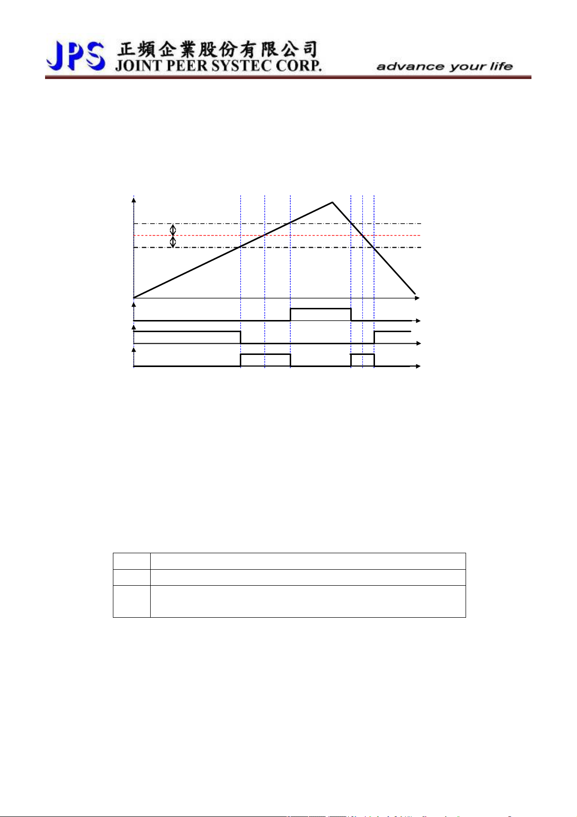
z DOx _ Select Æ 14,SPO (Speed Over compared value), Speed >= (Pr.207+Pr.208)
(14)
(15)
)
z DOx _ Select Æ 15,SPU (Speed Under compared value), Speed<= (Pr.207-Pr.208)
z DOx _ Select Æ 16,SPE (Speed Equal), the different between Speed and Pr.207 < Pr.208
Description: Refer to the figure below.
If the motor’s speed reaches or exceeds Pr.207+Pr.208, the output terminal DOx(14) will be active.
If the motor’s speed is equal or under “Pr.207 - Pr.208”, the output DOx(15) will be non active.
If the motor’s speed is between Pr.207-Pr.208 and Pr.207+Pr.208, the output DOx(16) will be active.
RPM
Pr. 207
DOx
DOx
DOx (16
Pr.208
Pr.208
13.5 Speed Up / Down Counter
There is a embedded module called Speed Up / Down Counter; it has two types of function:
1.
Counting by trigger type
2.
Counting by time type
All the two types function of timer are used to be a speed command source, and can be used by selecting
the Pr.278 function type 2.
13.5.1 Speed Up/Down Counter Parameters
z Pr.104 Î Speed Up / Down Counter start type.
This parameter defines the start value of Speed Up / Down Counter.
Value Description
0 After power-on or reset the Speed Up / Down Counter start from 0.
After power-on or reset the Speed Up / Down Counter start from the
1
preloaded value that was set in Pr.105.
z Pr.105 Î Speed Up / Down Counter preload value
If Pr.104 = 1, the Speed Up / Down Counter will preloaded a start value from Pr.105.
If DIx(95) is trigged, the value of Speed Up / Down Counter will be stored into Pr.105.
z Pr.106 Î Speed Up / Down Counter change volume by trigger
This parameter defines the change volume that will be changed for Speed Up / Down Counter
when every trigger happened.
When trigger DIx(91), the counter will increase a volume of Pr.106.
When trigger DIx(92), the counter will decrease a volume of Pr.106.
www.jps.com.tw
74

z Pr.107 Î Speed Up / Down Counter change volume by time
This parameter defines the change volume that will be changed for Speed Up / Down Counter
in every second.
When DIx(93) is ON, the counter will increase a volume of Pr.107 in every second.
When DIx(94) is ON, the counter will decrease a volume of Pr.107 in every second.
z Pr.117 Î Up/Dn Data Temperary Value
This parameter display Up/Dn Result value。
www.jps.com.tw
75

13.5.2 Speed Up/Down Counter Digital-Input
z DIx _ Select Æ 90,Up/Down Buffer Clear to Zero
If input is active, clear the Speed Up / Down counter register to be 0 when be active.
z DIx _ Select Æ 91,Up/Down Buffer Trig. INC
If the input is active, increase the Speed Up / Down Counter (Pr.106) when be active.
z DIx _ Select Æ 92,Up/Down Buffer Trig. DEC
If the input is active, Decrease the Speed Up / Down Counter (Pr.106) when be active.
z DIx _ Select Æ 93,Up/Down Buffer Level-INC
Increase the Speed Up / Down Counter by a preset value in Pr.107 every second.
z DIx _ Select Æ 94,Up/Down Buffer Level- DEC
Decrease the Speed Up / Down Counter by a preset value in Pr.107 every second.
z DIx _ Select Æ 95,Up/Down Buffer "SAVE Buffer to Pr.105"
Save Speed Up / Down Counter value into Pr.105.
13.5.3 Speed Up/Down Counter Digital-Ouput
www.jps.com.tw
76

13.5.4 PulseType-Speed Up/Down Counter
Clr S
DIx(91)
DIx(92)
DIx(90)
Up/Down Module
Up
Down
Up / Down
Counter
(Pr.106)
Speed command
Pr.104
DIx(95)
Set all the parameters as the drawing showed in front of here. The start value of Speed Up / Down
Counter can be determined by selecting the type of Pr.104 to start from 0 or preload a value from
Pr.105.
The following timing chart describes the DI and DO status of Speed Up / Down Counter.
rpm
+4 Pr.106
+3 Pr.106
+2 Pr.106
+1 Pr.106
0
DIx(91)
DIx(92)
ave
Pr. 105
△ = Pr.106
DIx(90)
DIx(95)
Description:
1.
The start value can be determined by selecting type of Pr.104 to start from 0 or a preloaded value
of Pr.105. In here, it start from 0.
2.
When DIx(91) is trigged, the output of counter will increase a value of Pr.106.
3.
When DIx(90) is trigged, the output of counter will be cleared to 0.
4.
When DIx(92) is trigged, the output of counter will decrease a value of Pr.106.
5.
When DIx(95) is trigged, the value of counter will be stored into Pr.105.
www.jps.com.tw
77

13.5.5 Level Type-Speed Up/Down Counter
Clr S
DIx(93)
DIx(94)
DIx(90)
Up/Down Module
Up
Down
Up / Down
Counter
(Pr.107)
Speed command
Pr.104
DIx(95)
Set all the parameters as the drawing showed in front of here. The start value of Speed Up / Down
Counter can be determined by selecting the type of Pr.104 to start from 0 or preload a value from
Pr.105.
The following timing chart describe the DI and DO status of Speed Up / Down Counter.
rpm
+4 Pr.107
+3 Pr.107
+2 Pr.107
+1 Pr.107
0
0 1 2 3 4 5 6 7 8 9 10 11 13 14 sec12
DIx(93)
ave
Pr.105
△ = Pr.107
DIx(94)
DIx(90)
DIx(95)
Description:
1.
The start value can be determined by selecting type of Pr.104 to start from 0 or a preloaded value
of Pr.105. In here, it start from 0.
2.
When DIx(93) is trigged, the output of counter will increase a value of Pr.107 for every second.
3.
When DIx(90) is trigged, the output of counter will be cleared to 0.
4.
When DIx(94) is trigged, the output of counter will decrease a value of Pr.107 for every second.
5.
When DIx(95) is trigged, the value of counter will be stored into Pr.105.
www.jps.com.tw
78

13.6 Rotary Switch Group
The Rotary Switch function is used to set frequency or speed of the drive.
13.6.1 Rotary Switch Group Parameters
z Pr.118 Æ RSW TYPE
This parameter can define the type of the Rotary Switch. There are for types can be select.
Value description
After RESET, the Pr.137(RSW data) will start from 0, and the max. value will be
0
limited by the setting of Pr.152.
After RESET, the Pr.137(RSW data) will start from Pr.138, and the max. value will
1
be limited by the setting of Pr.152.
After RESET, the Pr.137(RSW data) will start from 0, and the max. value will be
2
65535.
After RESET, the Pr.137(RSW data) will start from Pr.138, and the max. value will
3
be limited 65535.
When select 0 or 1, the speed is calculated by the equation showed below:
Rpm = Pr.137 / Pr.152 * Pr.128
When select 2 or 3, the speed is calculated by the equation showed below:
Rpm = Pr.137 / 65535 * Pr.128
z Pr.137 Æ RSW Data
This parameter can show the pulse count that come from the Rotary Switch A/B phase clock.
The frequency of the A/B clock is multiplied by 4 times inside the drive.
【NOTE】Because the frequency of the A/B clock, every step of the Rotary Switch will cause the
record of Pr.137 to increase 4 or decrease 4 counts.
z Pr.138 Æ RSW Backup Memory
This parameter defines the value that can be the default of the Pr.137 or save the Pr.137 value.
z Pr.152 Æ RSW Max Data Limit
This parameter defines the max. limit of the Pr.137 value.
【NOTE】Please refer to paragraph 0 11. Digital Input Function for detailed.
13.6.2 Rotary Switch Group Digital-Input
z DIx _ Select Æ 203,Rotary Switch signal-A input.
This function defines the terminal to be the input of Rotary Switch signal-A.
z DIx _ Select Æ 204,Rotary Switch signal-B input.
This function defines the terminal to be the input of Rotary Switch signal-B.
【NOTE】These two DI functions should be defined at the same time. The signal
A and B are used to define the direction and 4-times frequency accuracy
of the Rotary Switch pulse train.
z DIx _ Select Æ 205,Rotary Switch signal-Store input.
This function defines the terminal to be the input of Rotary Switch pulse count
store; when this function is active, the value in Pr.137 (RSW Data) will be stored
into Pr.138 (RSW Backup Memory).
www.jps.com.tw
79

13.6.3 Rotary Switch Group Digital-Output
Example for using Rotary Switch:
1.
Set the speed limit Pr.128 = 2000.
2.
Pr.065 = 73 Æ Set FWD.
3.
Pr.066 = 74 Æ Set REV.
4.
Pr.278 = 19 Æ Select speed command set from Rotary Switch.
5.
Pr.118 = 0 Æ Select Rotary Switch type: Start from 0, with max. limit.
6.
Set DI1(203), DI2(204), DI3(205) Æ Set the input definition for Rotary Switch.
7.
Pr.152 = 1000 Æ Set max. limit value of Rotary Switch.
8.
Connect the signals A, B, Store of Rotary Switch to the DIs those were defined by step 6.
9.
It is necessary to reset the drive to let the changes available.
10.
Start to run forward and the drive will run in the speed that set by Rotary Switch. If the Rotary Switch
is see in 500, the speed will be Pr.137 / Pr.152 * Pr.128 = 1000rpm.
11.
Press the Store bottom, the value in Pr.137 will be stored into Pr.152.
www.jps.com.tw
80

13.7 PID Function
13.7.1 PID Function Parameters
z Pr.278 Æ Select Speed Source when SWx=000
This parameter select speed source。
【Note】When set value = 21,speed source = PID block as main speed。
z Pr.236 Æ PID-SET Value(Belong to RAM)
This parameter set PID-Value。
【Note】this parameter set value belong to RAM,preset to default after reset or power off。
z Pr.237 Æ PID-PILOT Value(Belong to RAM)
This parameter set PID-Pilot。
【Note】this parameter set value belong to RAM,preset to default after reset or power off。
z Pr.238 Æ PID-ERROR Value
This parameter display PID-Error。
z Pr.255 Æ PID-P-Gain1
This parameter set PID-P-Gain1。
【Note】Normally set method,I-gain > P-gain。
z Pr.256 Æ PID-I-Gain1
This parameter set PID-I-Gain1。
【Note】Normally set method,I-gain > P-gain。
z Pr.257 Æ Reserved
z Pr.258 Æ Reserved
These parameters belong to factory only,please do not set。
z Pr.279 Æ PID-CONSTANT Value(Belong to ROM)
This parameter set as constant value,can set as PID source or feedback。
【Note】This parameter belong to ROM,keep value after reset or power off。
z Pr.280 Æ PID-Select-Source of SET Value
z Pr.281 Æ PID-Select-Source of PILOT Value
value Item description
0 RAM as Set Data (Pr.236)
1 RAM as Set Data (Pr.237)
2 ROM as Set Data (Pr.279)
3 AI1 as Set Data (Pr.234)
Actual Speed(normalized)
4
as Set Data
RSW as Set Data
5
(100%*Pr.137/152)
Use Pr.236,as PID set,belnog to (RAM),
preset to default after reset or power off
Use Pr.237,as PID set,belnog to (RAM),
preset to default after reset or power off
Use Pr.279,as PID set,belnog to (ROM),
Keep value after reset or power off
Use AI1%,as PID set,
AI1data can check with Pr.236
Use actual speed,as PID set
Use RSW(Rotary Switch Data) as PID set,
Resolution=(100%×Pr.137/Pr.152)
www.jps.com.tw
81

z Pr.282 Æ PID-Output Limit
value Item description
0 STOP PID block Stop PID block function
PID-Output = Bi-Directional
Bi-Directional Output
1
※ When range = -32767~0:Reverse Run
(+/-32767)
※ When range = 0~+32767:Forward Run
Uni-Directional Positive
PID- Output = Positive side
2
Output (0 ~ +32767)
Uni-Directional Negative
※ When range = 0~+32767:Forward Run
PID- Output = Negative side
3
Output (0 ~ -32767)
z Pr.292 Æ PID-OUTPUT Value
※ When range = -32767~0:Reverse Run
This parameter display PID-Output。
【Note】This parameter follow set resolution of Pr.282,produce PID output。
z Pr.295 Æ PID-P-Gain2
This parameter set PID-P-Gain2。
【Note】Normally set method,I-gain > P-gain。
z Pr.296 Æ PID-I-Gain2
This parameter set PID-P-Gain2。
【Note】Normally set method,I-gain > P-gain。
z Pr.297 Æ PID-Gain-Switch Point
PID switch point = (PID gain switch speed / Max speed)× 100%
Pr.297 = XX.YY,include XX and YY,two sets value。
XX = PID-1 gain switch point,YY = PID-2 gain switch point,
When (Actual speed / Max speed)× 100% > XX
When (Actual speed / Max speed)× 100% < YY
When (Actual speed / Max speed)× 100% between XX.YY
Æ use PID-1 gain
Æ use PID-2 gain
Æ use linear gain of PID1/PID2
※ YY shoulde be larger then XX,if YY > XX,driver will set YY as switch point of PID2
,and set XX as switch point of PID1。
www.jps.com.tw
82

13.7.2 PID Function Digital-Input
)
z DIx_Select Æ 70,PID --> ENABLE PID Block
When select this function,enable PID block。
13.7.3 PID Function Digital-Output
13.7.4 PID Function Block
PID Set
PID Error
PID Process
P Gain
I Gain
PID Output
PID Enable DIx(70
PID block compare with PID-Set and PID-Pilot,and produce the result:PID-Error
Formule: ----------------(1-1)
【Example】:
Pr.128:Motor Maximun speed limit = 1000
Pr.297:PID-switch point = 80.20
Pr.255:PID P- gain1 = 500
Pr.256:PID I - gain1 = 50
Pr.295:PID P-gain2 = 100
Pr.296:PID I - gain2 = 10
※ When actually speed > 800rpm,main gain = PID- Gain1
※ When actually speed < 200rpm,main gain = PID-Gain2
※ When actually speed between 200rpm ~ 800rpm,main gain = linear adjustment。
PID High Gain
Rpm
1000
800
600
ÎXX =(800/1000)×100% = 80%;YY =(200/1000)×100% = 20%
ErrorIgainPgainErrorOutputPID +×=
∫
dt
400
PID Low Gain
www.jps.com.tw
200
80%
83
20%

(
(73)
14. PCMD Mode
14.1 PCMD Rule
z The software version shoud contain the PCMD functions, the content of Pr.337 should be 201 (the PCMD
special function)
z The driver should be in the mode of closed loop
14.2 PCMD Connection
PCMD
5V Line Driver
Input Line speed
G24
DI-1
220)
DI-2(222)
DI-3(223)
DI-4(224)
DI-5
IRIS Servo Drive
DB1(F) XY Input
Enable Simulated XY input pulse
Switch to Speed Command Mode
Change XY input pulse direction
Enable Pulse Command mode
Forward Run
DB3(M) PG Output
DB2(M) PG Input
To Slave
To Encoder
www.jps.com.tw
84

14.3 PCMD Function Block
Master Speed Source CMD
Pr.278=10
Pulse CMD Mode
Pr.278
Speed Source Select
Pr.278=0
Speed CMD Mode
XY Pulse
Pr.399 X/Y
Input Direction
Pr.450 XY MULTIPLY
Pr.451 XY DIVIDE
Pr.452
XY Command Type
Pr.396 PCMD:
Position Servo-Gain
Pr.456 XY MULTIPLY
Execute-Value(RAM)
Pr.452=0 XY QEP Type
Pr.452=1 X: Enable Y:CKinput
Actual Position CMD
www.jps.com.tw
85

14.4 PCMD Function Group
14.4.1 PCMD Group Parameters
z Pr.396 Î Servo position gain
When setting 10000, the position comsumption is calculated as the speed of 10000 rpm per
every revolution.
z Pr.398 Î X/Y Pulse Counter
This parametrer contents the XY input pulse counts; the input pulse counts will be increased
by positive direction pulse and decreased by negative direction pulse.
z Pr.399 Î X/Y Input DIRECTION
For changing the XY pulse direction.
【Note】After change the value of this parameter, the drive should be resetted.
【Note】DIx(223) has same function but it’s priority is greater then Pr.398.
z Pr.450 Î X/Y MUL1 Setting-Value(ROM)
z Pr.451 Î X/Y DIV1(ROM)
The above two parameters are used to modify the speed rate for XY input pulse and motor.
【EXP】If the input pulses are 10000 and wish motor to move 1024 pulses, Pr.399 should be
1024 and Pr.450 should be 10000.
z Pr.452 Î X/Y Commad Type
Can set the format of XY input pulse.
Setting X/Y Commad Type
Tow phase pulse train.
X
0
Y
2
3
5 1
4 6
7
9
A
8
8
9
6
7
A pulse clock train and a direction indicae signal.
z Y input is clock train.
z Using DIx(223) to accept the direction indicate signal.
Y
1
DIx(223)
1 2
3 4 5 3
4 2
【Note】The variation will be effected only after the drive is resetted.
5
www.jps.com.tw
86

z Pr.453 Î X/Y Pcmd Sampling time
The speed feed volumn is calculated by the pulses counted within some period. The time
period is setted by this parameter.
If Pr.452 is small, the response will be fast but the system will vibrate easily.
If Pr.452 large, the response will be slow but the system will be more stable.
z Pr.454 Î X/Y Pcmd Feed forward Gain
If setting 50% to this parameter and the speed feed volumn is 1000 rpm, then the actual feed
volumn is 500 rpm.
※ for normal condition, the value 100% for this parameter is recommended.
z Pr.455 Î X/Y Input Status
This parameter displays X/Y input status,status = 0、1、2、3。
【Note】if value=2,mean X signal is on status;if value=1,mean Y signal is on status。
z Pr.456 Î X/Y MULx Execute-Value(RAM)
XY Multi factor parameter,belong to RAM type,change this parameter will change Pcmd
Factor immediately。
【Note】This parameter will be put by program after reset every time。
Allow on-line change。
z Pr.470 Î Position Tracking Error
This parameter displays tracking error when Pcmd activity。
www.jps.com.tw
87

14.4.2 PCMD Group Digital Input
z DIx _ Select Î 220,,Enable the simulated XY input pulse.
When this input is “ON”, the simulated XY input pulse function is enabled.
When this input is “OFF”, the simulated XY input pulse function is diabled.
【Note】The simulated XY input pulse is related to the Pr.239 contents; therefore,
please don’t change the Pr.239 if is not necessary (the default setting is
10kHz). This function also guarded by DIx(224) situation.
z DIx _ Select Î 221,Switch from Speed Command to Pulse Command.
When set “ON”, the control mode is switched to Pulse Command mode.
When set “OFF”, the control mode is switched to Speed Command mode.
z DIx _ Select Î 222,Reversed definition of function 221.
When set “ON”, the control mode is switched to Speed Command mode.
When set “OFF”, the control mode is switched to Pulse Command mode.
z DIx _ Select Î 223,Change the direction of XY input pulse
When set “ON”, the direction definition of XY input pulse will be changed to the
reversed definition of the original.
The input pulse counts status: increased
Decreased
z DIx _ Select Î 224,Enable Pulse Command mode.
When set “ON”, the Pulse Command mode is enabled.
When set “OFF”, the Pulse Command mode is disabled.
z DIx_Select Î 226,PCMD-> Pcmd Input Clocks Enable + XYM online change
When set “ON”,enable Pcmd enabled and XY-online adjustment。
When set “OFF”,not allow any external command,drive stop running。
【Note】when eable this function i,program allow Pr.450 setting value。
Î decreased;
Î increased.
14.4.3 PCMD Group Digital Output
www.jps.com.tw
88

14.5 PCMD Function Basic Example
14.5.1 PCMD Parameter Setting
Step 1: Setting DI function
Pr.061=220 > DI1: Enable Simulated XY input pulse.
Pr.062=222 > DI2: Switch to Speed Command mode.
Pr.063=223 > DI3: Change XY input pulse direction.
Pr.064=224 > DI4: Enable Pulse Command mode.
Pr.065=73 > DI5: Forward Run.
Step 2: Setting relative parameters
Pr.278=10 >【Speed Command Select】Speed source from PCMD mode.
Pr.396=1000 >【SERVO-GAIN】
Pr.452=0 >【XY command type】
Pr.450=10000 >【XY MUL1】
Pr.451=10000 >【XY DIV1】
Pr.454=100 >【XY Forward Gain】if slower respone is needed, pleae set to lower value.
【Note】After setting Drive needs to be reset
After Reset,Pr450 value will move to Pr.456,as main PCMD multi executing value。
14.5.2 PCMD Start
【Note】In case of avoiding damage, please pre-excute the process in the condition that motor is not linked
to transmit system.
DI5(73): Forward Run > Keep in “ON” state
DI2(222) Switch to Speed Command mode > Keep in “OFF” state
DI4(224): Enable Pulse Command mode > Keep in “ON” state
DI1(220): Enable simulated XY input pulse > Keep in “ON” state
【Note】If the motor runs in forward direction, the drive is operating correctly and might go on next step;
if not, check all settings.
DI1(220): Disable Simulated XY input pulse > Keep in “OFF” state
【Note】In this moment, the pulse train from XY inpu port will decide the speed of motor.
www.jps.com.tw
89

15. Alarm Message and Maintenance
15.1 Display of Alarm Message
Ala rm Re cor d
position, and the A0 will be clear to record the current status.
The Alarm Message description will be explained in next paragraph.
Alarm
Icon
Alarm
Message
When alarm happened, the LCD display will show message as the
figure showed in the left side. If used panel is COLOR type, the display
back light will turn to red.
The items of the alarm message are Alarm Record and Alarm Message.
The current alarm record is A0, and user can press the up or down keys
to check the earlier records A1, A2, A3.
Every time the drive turned on, the alarm records will be shift to earlier
15.2 Maintenance of Alarm Message
When the panel enter the alarm mode, it means that there is important message to show on the LCD display.
The user should treat this condition by following the setps introduced below with serious maner. If still cannot
fix the problem after these methods mentioned in here, please contact with product agency or maintain
department of manufacturer. The basicaly maintenance steps are described below:
Alarm message Description and maintenance
A0 – no
When showing
Î No Alarm
no presents there is no alarm.
z If the driver is in normal condition, the display will show like this way when enter
alarm mode.
A0 – PG
When showing
z Check the connection of feed back cable. Is there any broken or defect?
z If the feed back cable is long, make sure there is no serious interference to the
z Check the setting of Pr.193 (Magnetic Sensor Check Time) is proper or not.
z Because the reason of this problem may includes magnetic sensor, therefore,
Î PG feed back Alarm
PG presents the encoder feed back signal error.
cable.
before sending the driver for maintenance, it is better to replace the driver with
another good condition one to make sure the problem is caused by driver
individually.
www.jps.com.tw
90
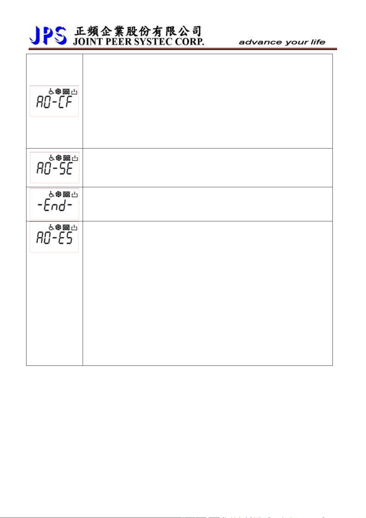
A0 – CF
When showing
z Check if the fan is stalled by dust.
z Check the setting of Pr.149 (FAN Low Speed Warning and Trip Level) is proper or
z Set the parameter Pr.146 (FAN Control Type) = 1 to force the fan running, and
A0 – SE
When showing
z Contact with agency or send the driver back for maintenance.
- End -
When showing
z This message is used to indicate procedure status and is not an alarm message.
A0 – ES
Î FAN Alarm
CF presents the fan speed is too low or failed to run.
not. Normally the fan speed is in 3000~4000rpm; therefore, this parameter should
set for 2000~2500rpm for proper check level.
check the running condition of fan to confirm the fan is in good condition or not.
If the fan is out of work, replace it.
Î Memory Alarm
SE presents the EEPROM is not in good condition.
Î Auto Tuning Procedure End
End presents the auto tuning procedure is finished.
Î Emergency Stop
When showing
emergency.
z Remove the input line of emergency stop signal from the driver’s input terminal.
Under safe condition, reset the driver. If the alarm message still exists, please send
this driver for maintenance.
z Check the wiring condition of the emergency stop signal. Is the line broken or
short with other signal?
z Check the emergency stop switch or signal generator. Is there any defect or miss?
z Is there any interference to cause the signal happened?
z If the emergency condition is indeed, contact with the system engineer to fix the
condition.
z Unless the emergency condition is fixed completely, the driver shouldn’t be
operated to run the motor.
ES presents that there is an external signal to order the driver stop for
www.jps.com.tw
91

A0 – Od
When showing
Pr.151 (Over Discharge Protect Time).
z Check the setting of Pr.151 is proper or not. If the setting is too short, it is easily to
z Check the load of motor. Is the inertia too large to generate great feed back
z Check the input power voltage of driver. Is the voltage exceeds the rating of
z Check if the setting of Pr.130 (Input Power Voltage) is suitable or not.
z Check if the displayed message of Pr.132 (DC Bus Voltage) is correct or not?
z According to the result of last 3 check items to decide if there is necessary to
A0 – OL
When showing
executed by the internal electronic thermo relay. When the accumulate thermo time
exceeds the setting value, the driver will trip and show this message.
z Check the setting of Pr.215 (Electronic Thermo Relay Time) is proper or not.
z Check the setting of Pr.210 (Motor Full Load Current Ratio) is correct or not.
z Check the setting of r Pr.211 (Motor Exciting Current Ratio) is correct or not.
z Check if the motor is stalled.
z Check if the load exceeds the rating of motor.
z Check if the variant of load exceeds the design specification.
A0 – OH
Î Over Discharge
Od presents the discharge time exceeds the setting in parameter
cause alarm. To set it for longer time, should consider if the resistor’s wattage is
enough or not.
energy?
input?
modify the setting of Pr.131 (DC Bus Measurement Adjust).
Î Motor Over Load
OL presents the motor is over load. The over load protection is
Î Heat Sink Over Heat or External Over Heat Protect
When showing
(Over Heat Protect Temperature) or there is an external over heat protect signal
happened.
z Check if the setting of Pr.150 (Over Heat Protect Temperature) is proper or not.
z Set the Pr.146 (Fan Control Type) = 1 to check the fan function. If the fan is out of
working, replace it.
z Check if the fan is stalled.
z Check if the condition of driver fit in the installation environment.
z Check if the ambient temperature exceeds the installation environment.
z The temperally variation of climate may cause ambient temperature to be high,
arranging a proper cooling method to prevent over heat contition is necessary at
this moment.
www.jps.com.tw
OH presents the heat sink temperature exceeds the setting of Pr.150
92

A0 – OP
Î Over Potential
When showing
z If it is caused by the regeneration when decreasing speed, apply a proper
discharge resistor to discharge circuits.
z Re-calculate the value of discharge resistor to fit in the volume of regeneration
energy.
z Check if the input power voltage exceeds the input rating of driver.
z Check if the setting of Pr.130 (Input Power Voltage) is correct or not.
z Check if the displayed message of Pr.132 (DC Bus Voltage) is correct or not.
z According to the result of last 3 check items to decide if there is necessary to
modify the setting of Pr.131 (DC Bus Measurement Adjust).
A0 – UP
When showing
z Check the input power system.
z Check the input power voltage fits in the rating of driver.
z Check if the setting of Pr.130 (Input AC Power Voltage) is correct or not.
z Check if the displayed message of Pr.132 (DC Bus Voltage) is correct or not.
A0 – OC
OP presents the dc bus voltage exceeds the protect level.
Î Under Potential
UP presents the dc bus voltage is lower the protect level.
Î Over Current
When showing
z Check if the type of motor fits in the driver’s specification.
z Check if the rating of motor’s fits in the rating of driver.
z Check if the connection of U, V, and W is properly or not.
z Check if the power lines to motor is broken or short with other lines or any defect.
z Check if the motor’s wires are short or not.
z Check the settings of parameter group BLAC Motor Group are correct or not.
z If the OC happened in the accelerating period, try to increase the setting of Pr.053
(Acc Time).
z If the OC happened in the decelerating period, try to increase the setting of Pr.054
(Dec Time).
z Check if the setting of Pr.130 (Input AC Power Voltage) is correct or not.
z Check if the displayed message of Pr.132 (DC Bus Voltage) is correct or not.
OC presents the output current exceeds the rating of driver.
www.jps.com.tw
93

16. CE Certificate
16.1 EMC Certificate
www.jps.com.tw
94

16.2 LVD Certificate
www.jps.com.tw
95

17. Control Panel Description
17.1 C-Panel Operational
When power-on start or reset the panel, the key will be locked and need user to unlock it. After user left it
after 10 minutes for not using, the panel will lock the keys automatically.
17.1.1 Lock and unlock
at least 1 sec, till 4 beeps sound.
Press
The panel will be unlocked.
z After unlock the panel, to do this proceedure again will lock the panel.
z Keep unprocees this panel for 10 minutes, the panel will lock the key function automatically.
z After unlock process, the display will show “unloc”; after lock process, display will show “loc”
17.1.2 Change mode
At any status Î
By pressing this bottom, can enter these different modes sequentially:
z Monitor mode
z Parameter mode
z Alarm mode
Press
17.1.3 Monitor mode
Select the monitoring item
When in
Monitor mode
Î
Press
By using the up/down keys, can select the monitoring item:
z N Motor’s speed.
z Hz The output frequency.
z A Output current.
z V Output voltage.
To run or stop the motor
When in
monitor mode Î
Press
Will start the motor to run, or
When in
monitor mode Î
Press
Will stop the motor.
or
twice
(within 0.5sec)
twice
(within 0.5sec)
www.jps.com.tw
96

In order to operate the run and stop function on the control panel, the condition list below should be
satisfied:
z Pr.065=0 FWD terminal function: no function.
z Pr.068=73 Set the virtual input function: FWD function.
z Pr.059=1 Control panel RUN / STOP function switch: enable.
17.1.4 Use the fly wheel function in the monitor mode
In monitor mode, can enter the fly wheel mode by touching and draw on the wheel.
or
If enter the fly wheel mode successfully, the icon
time, the display will show the present speed, and the latest digital will flash to notice that the data is
ready to be edit.
Use fly wheel and the up/down keys to edit data
z Change the edit position
Touch the right or left side
of the wheel lightly
By using this way, can change the edit positon to save the operation time.
z Edit the value
1.
Using the fly wheel to change the value
or to increase or decrease the value.
2.
Using up/down keys to change the value
will be showed on the display; in the mean
to change the edit
position.
press
Bothe of these two ways can be used to change the value.
z Write
twice within 0.5sec, the value will be written into
Press
www.jps.com.tw
memory.
or
to change the value.
97

17.1.5 Parameter mode (select, read, edit, write)
Press to enter parameter mode.
After enter parameter mode, LCD display will show Pr.000.
In the parameter mode should follow the steps list below to read or change the parameter’s value.
1.
Select parameter.
2.
Read out the value of parameter.
3.
Enter edit mode to change the value, if you wish.
4.
Write down the value into the parameter and save in memory.
5.
Exit from edit mode to select another parameter, or exit to the top level to change to another
operation mode.
Select the parameter
【NOTICE】All the operation described below can only work under the condition of the
By using the operation described below, can select parameter, read value, edit value and write the value
into parameter.
1.
Select parameter
z Enter select parameter mode
(parameter mode) or (edit mode).
Press
Touch one of the left or
right side of wheel
lightly.
By processes, least digital of displayed data will be flashed to indicate that is ready to be edit.
z Change the edit position
Touch the left
or right
or
to enter select parameter mode.
or
to enter select
parameter mode.
to change the edit
position.
z Enter parameter number
Press
Draw on the fly wheel
circularly
www.jps.com.tw
or
to increase or decrease value.
or
to change the value.
98

2.
Read the value of parameter
In
Edit parameter value
3.
Write down the parameter value
4.
The proceedures of editing and writing the parameter value are same with the proceedure that are
introduced in paragraph 0
5.
Use fly wheel and the up/down keys to edit data.
6.
Return
mode Î to read parameter value.
press
Press to return to previous mode sequentially.
Alarm mode
Press to select alarm mode.
In mode Î
Press
By using Up or Down keys, can show A0 ~ A3 alarm
z A0 Showing the present alarm message.
z A1 Showing the alarm message previous than A0.
z A2 Showing the alarm message previous than A1.
z A3 Showing the alarm message previous than A2.
After power on or reset, all alarm rec
** ord will be shift by the sequence A0
A0 will be refresh by present status.
or
messages sequentially:
then
ÆA1ÆA2ÆA3, and the record
17.1.6 RESET Function
In
mode Î Press
This procedure will reset the driver and panel itself, and the effect like power-on restart.
www.jps.com.tw
Twice within 0.5sec.
99
 Loading...