

JpS
IRIS-IMAC DRIVER
USER MANUAL
Version: V2.01
Software Rel.: V98.26
Panel Rel.: V9916
Safety Precautions and Warnings!
CAUTION! WARNING!
Pay attention to these
They indicate danger to human body or damage to the device. Before installing and putting the device into
operation, please read the safety precautions and warnings following this page.
1. Make sure that the warning signs are kept in a legible condition and replace missi ng or damaged signs.
2. Before starting, familiarize yourself with the operation of the inverter. It may be too late if you start working
with the inverter before read this instruction manual.
3. Never permit unqualified personnel to operate the inverter.
!
WARNING!
z This inverter produces dangerous electrical voltages and control s ro tating mechanical parts.
z Death, severe injury or substantial damage to property can occur if the instructions in this operating manual
are not completed with.
z Only personnel with appropriate qualifications should work with this inverter. These personnel must be
familiar with all the warning signs and precautions laid out in these operating instructions for the transpo rt,
installation and operation of this device.
z The successful and safe use of this inverter depends on the correct installation, commissioning, operation
and maintenance of the device.
z This device operates at high voltages.
!
CAUTION!
z The DC-link capacitors remain charged to dangerous voltages even the power is removed. For this reason it
is not permissible to open the inverter cover until five (5) minutes after the power has been turned off.
z When handling the open inverter it should be noted that live parts are exposed. Do not touch these live
parts.
z The terminals R, S, T, U, V, W, P, N, B, PR, and BR can carry dangerous voltages even if the motor is
inoperative.
z Only qualified personnel may connect, start the system up and repair faults. These personnel must be
thoroughly acquainted with all the warnings and operating procedures contained with this manual.
z Certain parameter settings may cause the device to start up automatically after power on or power recover.
!
CAUTION, WARNING, and
!
signals on the device or instruction documents.
DEFINITIONS
z Qualified Person
For the purposes of this manual and product labels, a qualified person is one who is familiar with the
installation, construction, operation and maintenance of this device and with hazards involved. In addition,
the person must be:
Trained and authorized to energize, de-energize, clear, ground and tag circuits and equipment in
accordance with established safety practices.
Trained in the proper care and use of protective equipment in accordance with established safety
practices.
Trained in rendering first aid.
z DANGER
For the purposes of this manual and product labels, DANGER indicates that loss of life, severe personal
injury or substantial property damage WILL result if proper precautions are not taken.
z WARNING
For the purposes of this manual and product labels, WARNING indicates that loss of life, severe personal
injury or substantial property damage CAN result if proper precautions are not taken.
z CAUTION
For the purpose of this manual and product labels, CAUTION indicates that min or personal injury or property
damage CAN result if proper precautions are not taken.
z NOTE
For the purpose of this manual and product labels, NOTES merely call attention to information that is
especially significant in understanding and operating the inverter.
1

!
DANGER and WARNING
z Make sure that the location selected for installation is safe, protected from moisture and spl ash and
drip-proof!
z Children and the general public must be prevented from accessing or approaching the equipment!
z The equipment may only be used for the purpose specified by the manufacturer. Unauthorized modifications
and the use of spare parts and accessories that are not sold or recommended b y the manufacturer of the
equipment can cause fires, electric shocks and injuries.
z Keep these operating instructions within easy reach and give them to all users!
!
WARNING
This is a Class A product. In a domestic environment this product may cause radio interference in which case the
user may be required to take adequate measures.
2
Contents
1. DESCRIPTION OF IRIS............................................................................................................................................... 5
1.1 CHECK ITEMS............................................................................................................................................................. 5
1.2 DESCRIPTION OF NAMEPLATE CONTENT.................................................................................................................... 5
1.3 THE SPECIFICATION OF IRIS SERIES........................................................................................................................... 6
2. CONDITION OF STORAGE ENVIRONMENT......................................................................................................... 7
3. ATTENTION OF INSTALLATION.............................................................................................................................. 7
4. OUTLINE DIMENSION................................................................................................................................................ 8
5. DESCRIPTION OF WI RING........................................................................................................................................ 9
5.1 POWER TERMINAL ..................................................................................................................................................... 9
5.2 THE CONTROL SIGNAL TERMINALS............................................................................................................................ 9
5.3 BRAKE RESISTOR TERMINALS.................................................................................................................................. 10
5.4 THE INPUT REACTOR ............................................................................................................................................... 10
5.5 THE PROPER SCREW DRIVE FOR POWER TERMINALS................................................................................................11
6. BASIC WIRING DIAGRAM FOR IRIS SERIES DRIVE ....................................................................................... 12
7. I/O INTERFACE........................................................................................................................................................... 13
7.1 THE MAP OF I/O TERMINAL POSITION ..................................................................................................................... 13
7.2 TM3 DESCRIPTION................................................................................................................................................... 14
7.3 CONNECTOR CON5 ................................................................................................................................................. 15
7.4 TERMINAL BLOCK TM1........................................................................................................................................... 15
7.5 CONNECTOR PG 1.................................................................................................................................................... 15
8. DIGITAL CONTROL PANEL DESCRIPTION ........................................................................................................ 16
8.1 DIGITAL CONTROL PANEL APPEARANCE INTRODUCTION .........................................................................................16
8.2 MONITOR'S GRAPHICAL DESCRIPTION ..................................................................................................................... 16
8.3 THE START UP MESSAGE OF PANEL.......................................................................................................................... 16
9. THE OPERATION GUIDE OF DIGITAL CONTROL PANEL..............................................................................17
9.1 LOCK AND UNLOCK.................................................................................................................................................. 17
9.2 CHANG E MOD E......................................................................................................................................................... 17
9.3 MONITOR MODE....................................................................................................................................................... 17
9.4 PARAMETER MODE (SELECT, READ, EDIT, WRITE) ..................................................................................................... 19
9.5 ALARM MODE .......................................................................................................................................................... 20
9.6 RESET .................................................................................................................................................................... 20
10. QUICK START......................................................................................................................................................... 21
10.1 RUN COMMAND SET FROM DIGITAL INPUT TERMINALS........................................................................................... 21
10.2 RUN COMMAND SET FROM CONTROL PANEL ..........................................................................................................21
10.3 CHANGE THE DEFINITION OF MOTOR’S DIRECTION ................................................................................................. 22
11. PARAMETER DESCRIPTION............................................................................................................................... 23
11.1 IRIS-IMAC PARAMETER LIST ................................................................................................................................. 23
11.2 MONITOR TYPE PARAMETERS’ ADDRESS ................................................................................................................. 26
11.3 PARAMETER’S TYPE................................................................................................................................................. 26
12. IRIS-IMAC PARAMETER DESCRIPTION......................................................................................................... 27
12.1 G00 DRIVER SPECIFICATION GROUP........................................................................................................................ 27
12.2 G01 DIGITAL INPUT GROUP ..................................................................................................................................... 28
12.3 G02 DIGITAL OUTPUT GROUP.................................................................................................................................. 29
12.4 G03 ANALOG INPUT GROUP..................................................................................................................................... 29
12.5 G05 ANALOG OUTPUT GROUP................................................................................................................................. 32
12.6 G07 MAGNETIC SENSOR GROUP.............................................................................................................................. 34
12.7 G10 IMAC MOTOR GROUP ..................................................................................................................................... 34
12.8 G15 IMAC CONTROL GROUP.................................................................................................................................. 35
12.9 G16 IMAC MULTI-SPEED SETTING GROUP .............................................................................................................39
12.10 G17 IMAC ACC/DEC/S-CURVE GROUP................................................................................................................ 39
12.11 G62 TIMER GROUP .............................................................................................................................................. 41
12.12 G64-MISC SPEED UP / DOWN COUNTER............................................................................................................. 41
12.13 G65 MISC. SPEED COMPARE GROUP................................................................................................................... 41
3

G66 MISC. ROTARY SWITCH GROUP................................................................................................................... 42
12.14
12.15 G82 H/W DC-BUS ADJUST GROUP..................................................................................................................... 42
12.16 G83 H/W THERMISTOR ADJUST GROUP............................................................................................................... 42
12.17 G84 H/W FAN ADJUST GROUP............................................................................................................................ 43
13. DIGITAL INPUT FUNCTION................................................................................................................................ 44
14. DIGITAL OUTPUT FUNCTION............................................................................................................................ 47
15. EMBEDDED MULTI-FUNCTION MO D ULE...................................................................................................... 49
15.1 TIMER ......................................................................................................................................................................49
15.2 SPEED UP / DOWN COUNTER.................................................................................................................................... 51
16. ALARM MESSAGE AND MAINTENANCE........................................................................................................54
16.1 ALARM MESSAGE ....................................................................................................................................................54
16.2 MAINTENANCE......................................................................................................................................................... 54
17. CE CERTIFICATE................................................................................................................................................... 57
17.1 EMC CERTIFICATE................................................................................................................................................... 57
17.2 LVD CERTIFICATE.................................................................................................................................................... 58
4
1. Description of IRIS
1.1 Check Items
To avoid the carelessness during packing and delivery, please check the list below carefully。
Items Amount Contents
IRIS IMAC Manual 1 book Please read carefully and keep with care for referring usage.
Check the spec. of the device with the case label is same or not.
IRIS IMAC Driver 1 set
Encoder Feedback cable 1 set
If any miss or defect happened, please contact with the agency to get resolve of the problem.
Check the out looking of the device to make sure that there is no
defect on it.
All screws should be tighten and exist.
Make sure it is contented in the package (the cable had been tested
before packing)。
1.2 Description of Nameplate Content
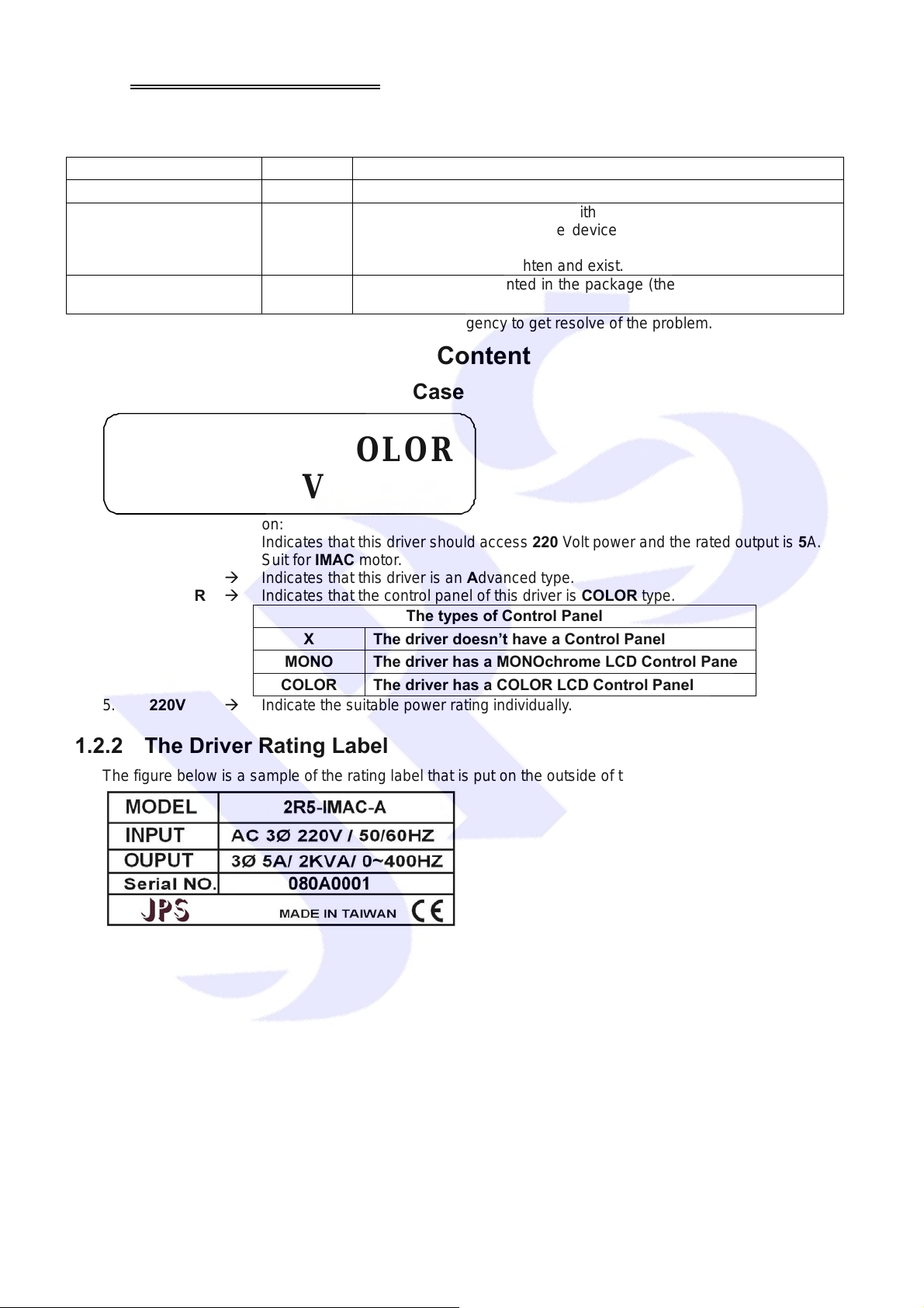
1.2.1 The Label on the Packing Case
2R5-IMAC-A-COLOR
220V
The contents of indication:
1. 2R5 Æ Indicates that this driver should access 220 Volt power and the rated output is 5A.
2. IMAC Æ Suit for IMAC motor.
3. A Æ Indicates that this driver is an Advanced type.
4. COLOR Æ Indicates that the control panel of this driver is COLOR type.
The types of Control Panel
X The driver doesn’t have a Control Panel
MONO The driver has a MONOchrome LCD Control Panel
COLOR The driver has a COLOR LCD Control Panel
5. 220V Æ Indicate the suitable power rating individually.
1.2.2 The Driver Rating Label
The figure below is a sample of the rating label that is put on the outside of the driver.
5
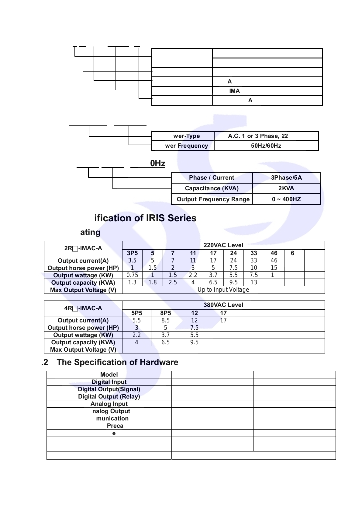
The contents of rating label are showed below:
MODEL:2 R □ - IMAC- A
INPUT :AC3Ø220 / 50/60HZ
OUTPUT : 3Ø5A 2KVA / 0~400Hz
Inp ut voltage
Model series R : IRIS Series
Output current According to Dr iver-Current
Suit mot or IMA C : Induct io n Moto r AC
Function A : Advanced
Pow er -Type A.C. 1 or 3 Phase, 220Volt.
Power Frequency 50Hz/60Hz
Pha se / Cur rent 3Pha se/5A
Capacita nce ( KVA) 2KVA
Output Frequency Range 0 ~ 400HZ
2 : 220VAC
4 : 380VAC
1.3 The Specification of IRIS Series
1.3.1 The Rating
2R□-IMAC-A
Output current(A)
Output horse power (HP)
Output wattage (KW)
Output capacity (KVA)
Max Output Voltage (V)
4R□-IMAC-A
Output current(A)
Output horse power (HP)
Output wattage (KW)
Output capacity (KVA)
Max Output Voltage (V)
1.3.2 The Specification of Hardware
Model 2R3P5~2R7 2R11~2R90 / 4R5P5~4R45
Digital Input
Digital Output(Signal)
Digital Output (Relay)
Analog Input
Analog Output
RS485 Communication Interface
Fan Malfunction & Precaution Function
Over Heat Protect Function
PG Feedback Interface
Brake Discharge MOS-FET
Digital Control Panel
3P5 5 7 11 17 24 33 46 61 90
3.5 5 7 11 17 24 33 46 61 90
1 1.5 2 3 5 7.5 10 15 20 30
0.75 1 1.5 2.2 3.7 5.5 7.5 11 15 22.5
1.3 1.8 2.5 4 6.5 9.5 13 19 25 34
5P5 8P5 12 17 23 31 45
5.5 8.5 12 17 23 31 45
3 5 7.5 11 15 20 30
2.2 3.7 5.5 7.5 11 15 22.5
4 6.5 9.5 13 19 25 34
1 Unit(12bit resolution) 2 Units(12bit resolution)
X:non-included ; M:Monochrome ; Color:Color
220VAC Level
Up to Input Voltage
380VAC Level
Up to Input Voltage
6 Unit 6 Unit
2 Unit 2 Unit
1 Unit 1 Unit
1 Unit 1 Unit
2 Unit 2 Unit
Included Included
Included Included
1Unit 1Unit
Included Included
6
2. Condition of Storage Environment
This driver should be contained in the packing case. If do not use this driver temporarily, in order to ensure this
driver in our warranty scope, please follow the items below:
z The ambient temperature must be in the scope of - 20℃ to +65℃, relative humidity 0% to 95%, and no dew
clings.
z Must be preserved in the environment that is dustless, stainless, and dry.
z Avoid to store under the environment that has caustic gas or liquid.
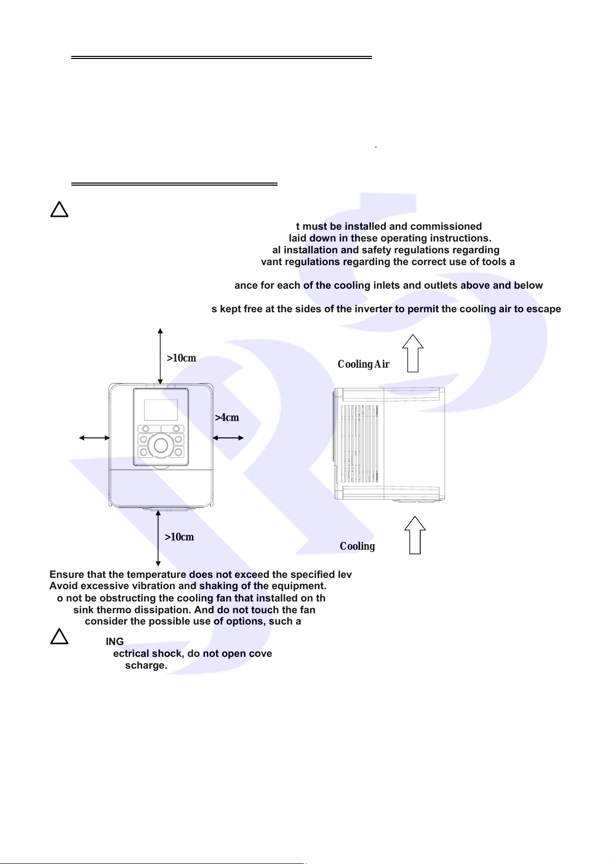
3. Attention of Installation
!
WARNING
To guarantee the safe operation of the equipment it must be installed and commissioned properly by
qualified personnel in compliance with warnings laid down in these operating instructions.
Take particular note of the general and regional installation and safety regulations regarding work on
high voltage regulations, as well as the relevant regulations regarding the correct use of tools and
personal protective gear.
Make sure that the unobstructed clearance for each of the cooling inlets and outlets above and below the
inverter is at least 100mm.
Make sure that a space of 40mm is kept free at the sides of the inverter to permit the cooling air to escape
from the side slits.
>10cm
>4cm
>10cm
Ensure that the temperature does not exceed the specified level when the inverter is installed in cubicle.
Avoid excessive vibration and shaking of the equipment.
Do not be obstructing the cooling fan that installed on the inverter, it is used to build proper airflow for
heat sink thermo dissipation. And do not touch the fan hole when it is running.
Please consider the possible use of options, such as RFI suppression filters at the planning stage.
!
WARNING
To prevent electrical shock, do not open cover for at least 5 minutes after removing AC power to allow
capacitors to discharge.
>4cm
Cooling Air
Cooling Air
7
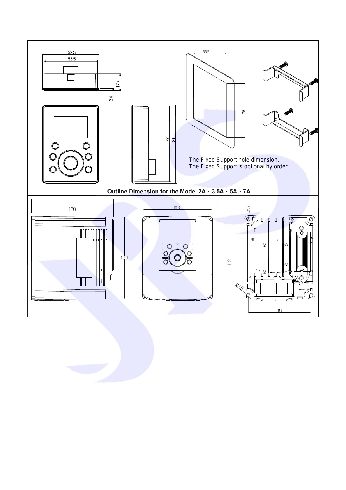
4. Outline Dimension
Control Panel The fixed Support of Control Panel
The Outline Dimension for the Model 2A、3.5A、5A,7A
The Fixed Support hole dimension.
The Fixed Support is optional by order.
8
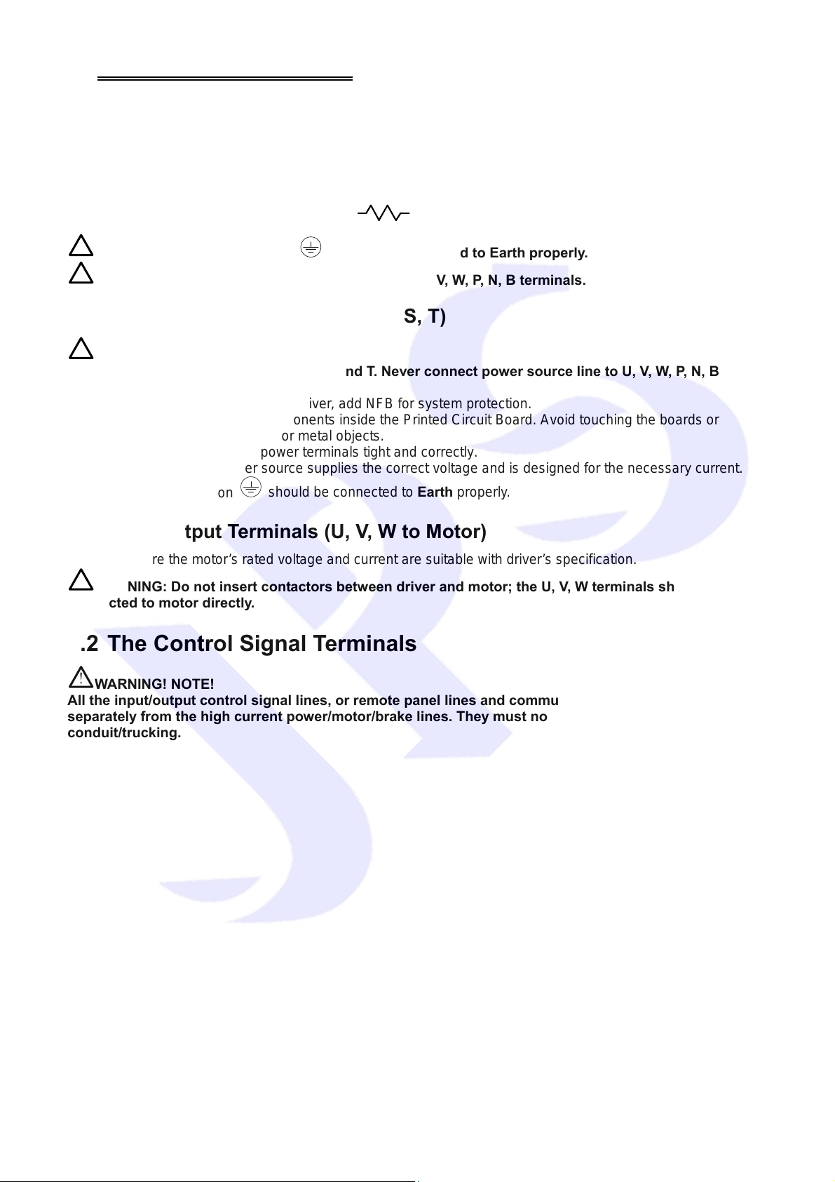
5. Description of Wiring
The upper cover must be removed in order to connect the electrical leads.
5.1 Power Terminal
The power terminals are divided into three portions:
1. The power input terminals (R, S, T) receives power fo r the operation of the inverter.
2. The output terminals (U, V, and W) deliver output power to motor.
3. Brake resistor should be connects to icon
!
NOTE: The terminal has icon should be connected to Earth properly.
!
WARNING: Never connect power source line to U, V, W, P, N, B terminals.
5.1.1 The Power Input Terminals (R, S, T)
!
WARNING! NOTE!
z The power input terminals are R, S, and T. Never connect power source line to U, V, W, P, N, B
terminals.
z Between the power source and driver, add NFB for system protection.
z There are static sensitive components inside the Printed Circuit Board. Avoid touching the boards or
components with your hands or metal objects.
z Make sure to connect the power terminals tight and correctly.
z Make sure that the power source supplies the correct voltage and is designed for the necessary current.
.
z The terminal has icon
should be connected to Earth properly.
5.1.2 The Output Terminals (U, V, W to Motor)
z Make sure the motor’s rated voltage and current are suitable with driver’s specification.
!
WARNING: Do not insert contactors between driver and motor; the U, V, W terminals should be
connected to motor directly.
5.2 The Control Signal Terminals
!
WARNING! NOTE!
All the input/output control signal lines, or remote panel lines and communication lines must be laid
separately from the high current power/motor/brake lines. They must not be fed through the same cable
conduit/trucking.
9
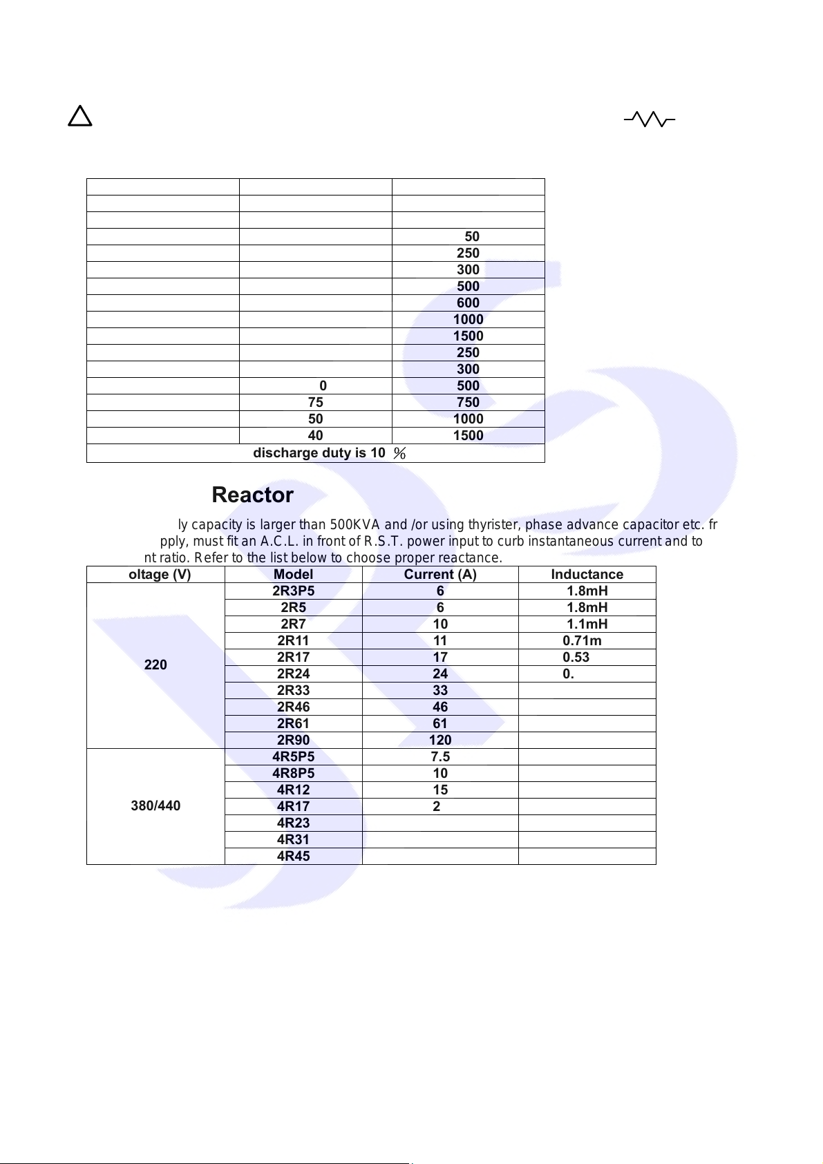
5.3 Brake Resistor Terminals
!
NOTE: This driver contains braking discharge circuits. The terminals have icon
connect external resistor to discharge the re-generating energy when in braking condition.
Refer to the list below when choosing resistor for braking discharge. The wattage of resistor can be
increased for heavier re-generating energy or higher discharge duty.
Model Resistance Wattage (W)
2R3P5 300 60
2R5 200 80
2R7 100 150
2R11 60 250
2R17 40 300
2R24 30 500
2R33 20 600
2R46 15 1000
2R61 10 1500
4R5P5 250 250
4R8P5 150 300
4R12 100 500
4R17 75 750
4R23 50 1000
4R31 40 1500
The discharge duty is 10 %
are used to
5.4 The Input Reactor
When power supply capacity is larger than 500KVA and /or using thyrister, phase advance capacitor etc. from
same power supply, must fit an A.C.L. in front of R.S.T. power input to curb instantaneous current and to improve
power efficient ratio. Refer to the list below to choose proper reactance.
Voltage (V) Model Current (A) Inductance
2R3P5 6 1.8mH
2R5 6 1.8mH
2R7 10 1.1mH
2R11 11 0.71mH
220
380/440
2R17 17 0.53mH
2R24 24 0.35mH
2R33 33 0.26mH
2R46 46 0.18mH
2R61 61 0.13mH
2R90 120 0.09mH
4R5P5 7.5 3.6mH
4R8P5 10 2.2mH
4R12 15 1.42mH
4R17 20 1.0mH
4R23 30 0.7mH
4R31 40 0.53mH
4R45 60 0.36mH
10
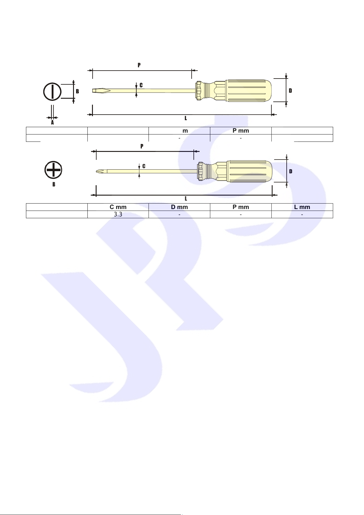
5.5 The Proper Screw Drive for Power Terminals
It is necessary to choose proper tool for wiring connection to avoid screw stripped or burst. Please refer to the list
below to choose a proper screw drive for driving power terminals.
A - B mm C mm D mm P mm L mm
0.6 - 3.3 3.3 - - -
B C mm D mm P mm L mm
#0 3.3 - - -
11
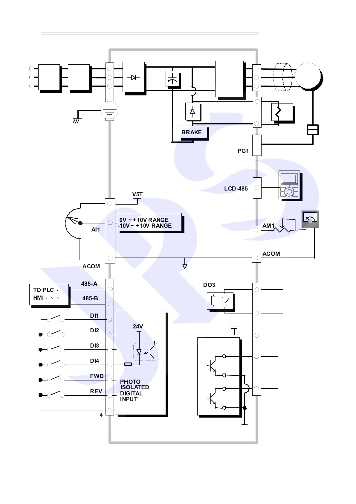
6. Basic Wiring Diagram for IRIS Series Drive
2
POWER
SOURCE
NFB
Filter
E
R
S
T
IGB T
BRAKE
PG1
U
V
W
EMI
MOTOR
POTENTIAL
METER
TO PLC、
HMI、、、
AI1
COM
485-A
485-B
DI1
DI2
DI3
DI4
V5T
0V ~ +10V RANGE
-10V ~ +10V RANGE
24V
LCD-485
DO3
24V
OPEN
COL LECTER
AM1
ACOM
RY3 A
MAX. RATING
00V, 3A
RY3 B
24V
DO1
FWD
REV
G24
PHOTO
ISOLATED
DIGI TAL
INPUT PORT
DO2
G24
12
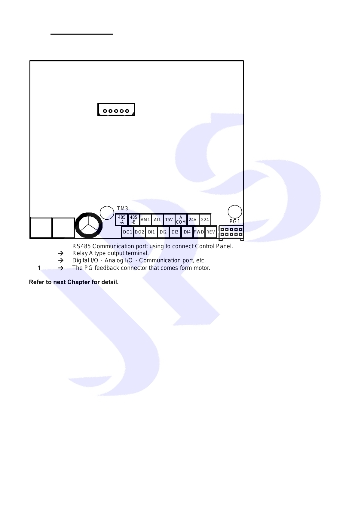
7. I/O Interface
7.1 The Map of I/O Terminal Position
Refer to the position map to locate the terminals or interface.
1
CON5
TM1
RY3A RY3B
TM3
485
485
-A
AM1 AI1 T5V
-B
DO1 DO2 DI1 DI2 DI3 DI4 FWD REV
A
COM
24V G24
PG1
CON5 Æ RS485 Communication port; using to connect Control Panel.
TM1 Æ Relay A type output terminal.
TM3 Æ Digital I/O、Analog I/O、Communication port, etc.
PG1 Æ The PG feedback connector that comes form motor.
Refer to next Chapter for detail.
13
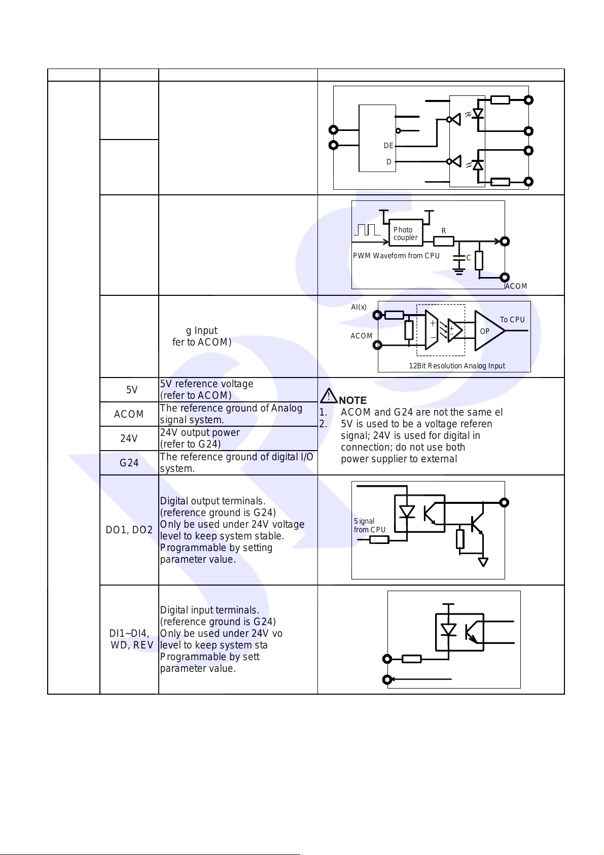
7.2 TM3 Description
C
A
G
A
A
A
AI(x)
)
V
-
(x)
Terminal Name Function Hardware construction
TM3
485-A
485-B
AM1
AI1
T5V
ACOM
24V
G24
RS485 communication port
(photo coupler isolated)
Analog output
(refer to ACOM )
Analog Input
(refer to ACOM )
5V reference voltage
(refer to ACOM )
The reference ground of Analog
signal system.
24V output power
(refer to G24)
The reference ground of digital I/O
system.
485-
485-B
B
PWM Waveform fr om CPU
COM
!
NOTE
CC
RX
R
ND
RE
DE
D
GND
Photo
coupler
12Bit Resolution Analog Input
R
C
To CPU
OP
M1
COM
VCC
TE
TX
VC
1. ACOM and G24 are not the same electric level.
2. 5V is used to be a voltage reference for analog
signal; 24V is used for digital input / output signal
connection; do not use both these two voltage as
power supplier to external circuits.
DO-(x
Digital output terminals.
DO1, DO2
(reference ground is G24)
Only be used under 24V voltage
level to keep system stable.
ignal
rom C PU
Programmable by setting
parameter value.
Open Collector
+24
4.7K
G24
G24
To CPU
GND
Digital Input
DI1~DI4,
FWD, REV
Digital input terminals.
(reference ground is G24)
Only be used under 24V voltage
level to keep system stable.
Programmable by setting
parameter value.
Digital Output
DI
G24
14
7.3 Connector CON5
Pin No. Function Description
Pin1 5V
Pin2 0V
Pin3 LCD-A
Pin4 LCD-B
Pin5 N.C.
Default designed to be the communication port of Control
Panel.
It is not suitable to apply to another communication usage.
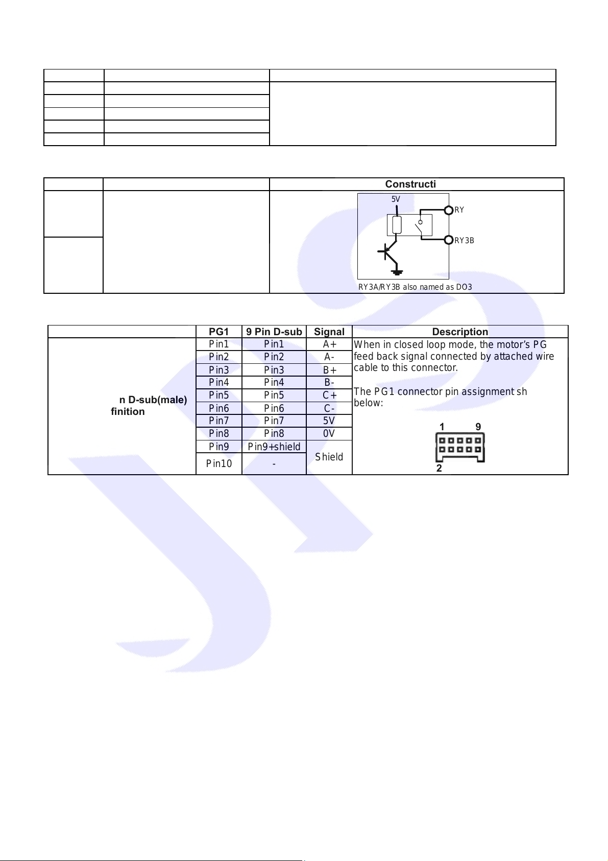
7.4 Terminal Block TM1
Terminal Function Construction
RY3A
RY3B
Relay A type output terminals.
Rating: 200V, 3A
Only be used under 24V voltage
level to keep system stable.
Programmable by setting
parameter value
RY3A/RY3B also name d as DO3
5V
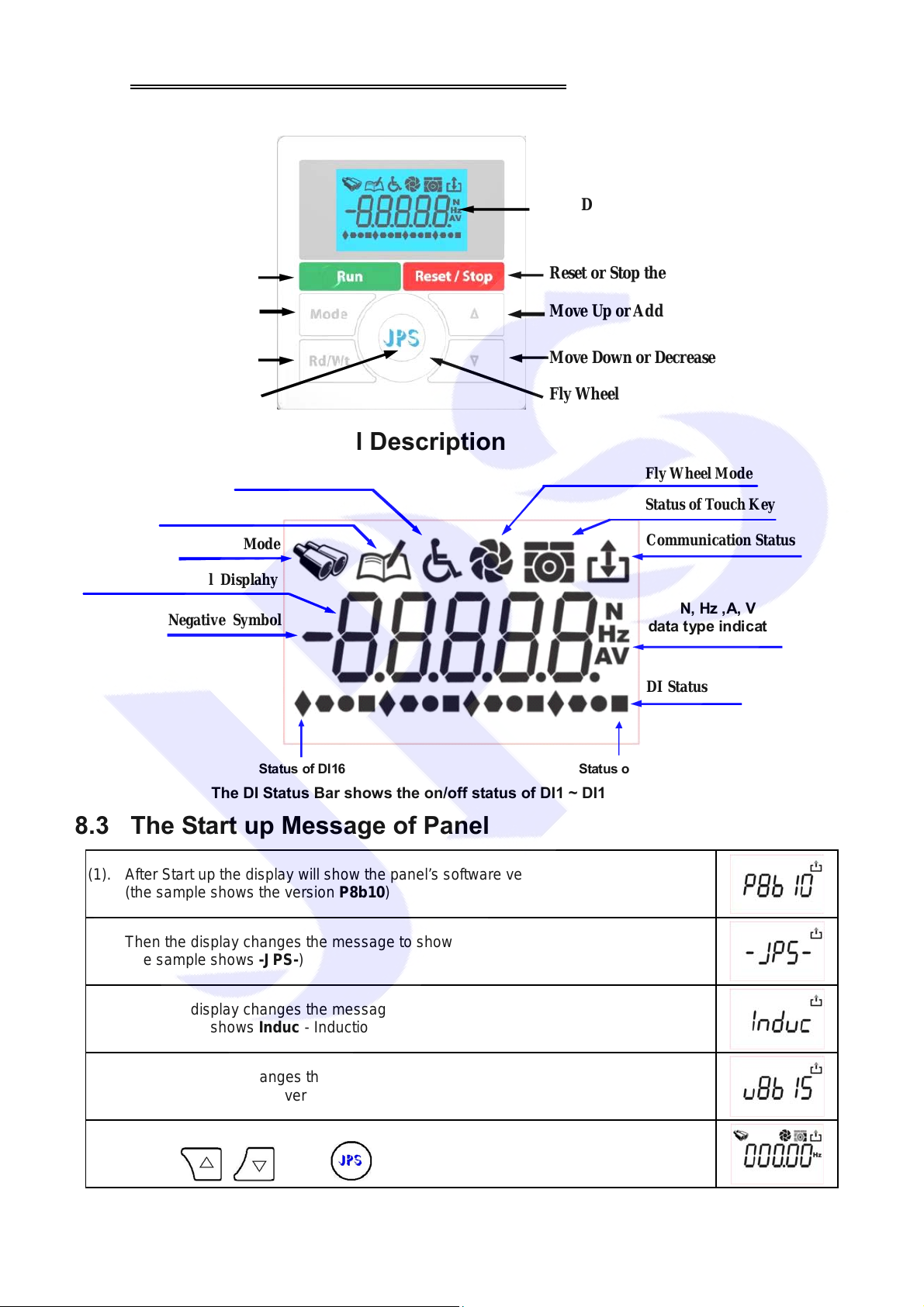
7.5 Connector PG 1
Connector PG1 9 Pin D-sub Signal Description
PG1 and 9-pin D-sub(male)
definition
Pin1 Pin1 A+
Pin2 Pin2 A-
Pin3 Pin3 B+
Pin4 Pin4 B-
Pin5 Pin5 C+
Pin6 Pin6 C-
Pin7 Pin7 5V
Pin8 Pin8 0V
Pin9 Pin9+shield
Pin10 -
Shield
When in closed loop mode, the motor’s PG
feed back signal connected by attached wire
cable to this connector .
The PG1 connector pin assignment show as
below:
2 10
RY3A
RY3B
1 9
15
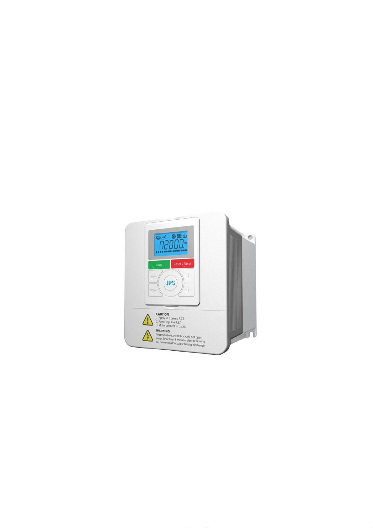
8. Digital Control Panel Description
k
r
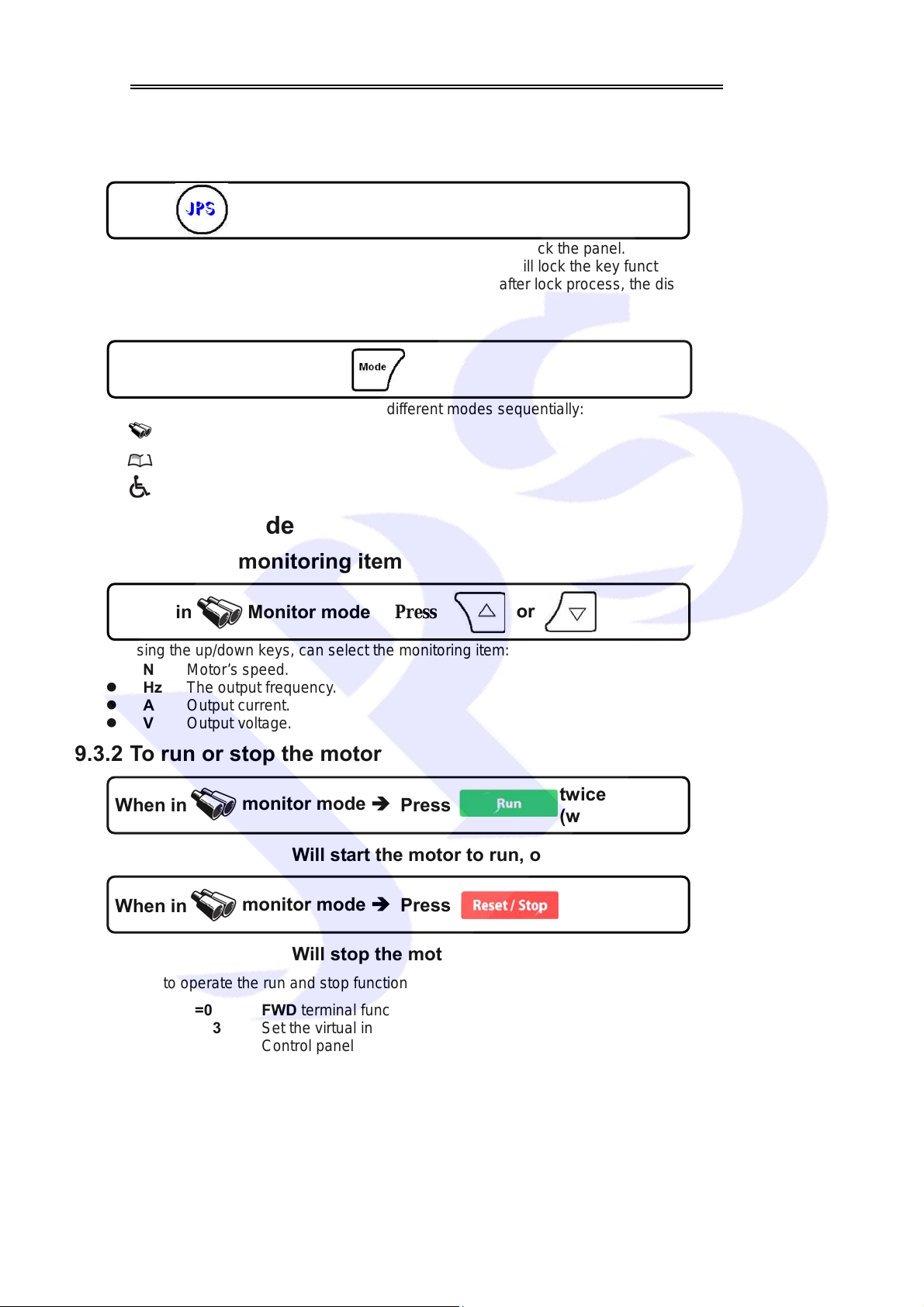
8.1 Digital Control Panel Appearance Introduction
LCD Display
Run the Drive
Mode Switch
Read / Write
Lock / Unloc
8.2 Monitor's Graphical Description
Alarm Mode
Parameter Mode
Monitor Mode
5-digital Numerical Displahy
Negative Symbol
Reset or Stop the Driver
Move Up or Ad d
Move Down or Decrease
Fly Wheel
Fly Wheel Mode
Status of Touch Key
Communication Status
N, Hz ,A, V
data t ype indi cator
DI Status Bar
Status of DI1 Status of DI16
The DI Status Bar shows the on/off status of DI1 ~ DI16 for real time.
8.3 The Start up Message of Panel
(1). After Start up the display will show the panel’s sof tware version firstly.
(the sample shows the version P8b10)
(2). Then the display changes the message to show company’s logo.
(the sample shows -JPS-)
(3). Then the display changes the message to show the fitting motor type.
(the sample shows Induc - Induction type)
(4). Then the display changes the message to show the driver’s software version.
(the sample shows the version v8b15)
(5). At last, the display changes the status to show the monitor mode.
Only
, and keys can be operated at this status.
16
9. The Operation Guide of Digital Control Panel
When power-on start or reset the panel, the key will be locked and need user to unlock it. After user
left it after 10 minutes for not using, the panel will lock the keys automatically.
9.1 Lock and unlock
Press
at least 1 sec, till 4 beeps sound.
The panel will be unlocked.
z After unlock the panel, to do this proceedure again will lock the panel.
z Keep unprocees this panel for 10 minutes, the panel will lock the key function automatically.
z After unlock process, the display will show “unloc”; after lock process, the display will show “loc”.
9.2 Change mode
At any status Î
By pressing this bottom, can enter these different modes sequentially:
z
z
z
Monitor mode
Parameter mode
Alarm mode
Press
9.3 Monitor mode
9.3.1 Select the monitoring item
When in
Monitor mode
Press
By using the up/down keys, can select the monitoring item:
z N Motor’s speed.
z Hz The output frequency.
z A Output current.
z V Output voltage.
or
9.3.2 To run or stop the motor
When in
monitor mode Î
Press
Will start the motor to run, or
When in
monitor mode Î
Press
Will stop the motor.
In order to operate the run and stop function on the control panel, the condition list below should be sati sfied:
z G01-05=0 FWD terminal function: no function.
z G01-08=73 Set the virtual input function: FWD function.
z G01-17=1 Control panel RUN / STOP function switch: enable.
twice
(within 0.5sec)
twice
(within 0.5sec)
17

9.3.3 Use the fly wheel function in the monitor mode
In monitor mode, can enter the fly wheel mode by touching and draw on the wheel.
or
If enter the fly wheel mode successfully, the icon will be showed on the display; in the mean time,
the display will show the present speed, and the latest digital will flash to notice that the data is ready to
be edit.
9.3.4 Use fly wheel and the up/down keys to edit data
z Change the edit position
Touch the right or left
side of the wheel lightly
By using this way, can change the edit positon to save the operation time.
z Edit the value
1. Using the fly wheel to change the value
to change the edit
position.
or to increase or decrease the value.
2. Using up/down keys to change the value
press
Bothe of these two ways can be used to change the value.
z Write
Press
twice within 0.5sec, the value will be written into
memory.
or
to change the value.
18

9.4 Parameter mode (select, read, edit, write)
Press to enter parameter mode.
After enter parameter mode, LCD display will show 00-00; the left side of hyphen is group nu mber, and the
left side is parameter number in the group; that is to say, the presently showed parameter is G00-00.
In the parameter mode should follow the steps list below to read or change the parameter’s value.
1. Select parameter.
2. Read out the value of parameter.
3. Enter edit mode to change the value, if you wish.
4. Write down the value into the parameter and save in memory.
5. Exit from edit mode to select another parameter, or exit to the top level to change to another
operation mode.
9.4.1 Select the parameter
【NOTICE】All the operation described below can only work under the condition of the
(parameter mode) or
By using the operation described below, can select parameter, read value, edit value and write the value into
parameter .
1. Select parameter
z Enter select parameter mode
(edit mode).
Pres
or
to enter select parameter
or
Touch one of the left
or right side of
to enter select
parameter mode.
wheel lightly.
By these processes, the least digital of displayed data will be flashed to indicate that is ready to be
edit.
z Change the edit position
Touch the left
or right
to change the edit
position.
z Enter parameter number
Press
or
to increase or decrease value.
or
Draw on the fly wheel
to change the value.
circularly
19

2. Read the value of parameter
In
mode
3. Edit parameter value
4. Write down the parameter value
The proceedures of editing and writing the parameter value are same with the proceedure that are
introduced in paragraph 9.3.4Use fly wheel and the up/down keys to edit data.
5. Return
Press
to return to previous mode sequentially.
9.5 Alarm mode
Press
to select alarm mode.
Î
press
to read parameter value.
then
In mode Î
Press
By using Up or Down keys, can show A0 ~ A3 alarm messages sequentially:
z A0 Showing the present alarm message.
z A1 Showing the alarm message previous than A0.
z A2 Showing the alarm message previous than A1.
z A3 Showing the alarm message previous than A2.
** After power on or reset, all alarm record will be shift by the sequence A0ÆA1ÆA2ÆA3, and the
record A0 will be refresh by present status.
or
9.6 RESET
In
mode ÎPress
This procedure will reset the driver and panel itself, and the effect like power-on restart.
Twice within 0.5sec.
20

10. Quick Start
10.1 Run Command Set from Digital Input Terminals
Step I Setting Basic Parameters and Auto Tuning (Close Loop)
A. Setting the Parameter of Motor
Refer to the nameplate on motor to set the following parameters:
1. G10-00 Full Load Current (%)
This parameter defines the percentage of the motor’s rating and the driver’s rating.
Full Load Current (%) = (Rated Current of Motor / Rated Current of Driver) x 100%
2. G10-02 Motor Pole No.
3. G16-08 Max. RPM Limit
B. Execute R&L Auto Tuning
1. Setting G15-00 (Motor Operation Mode) to be 7 (select R&L Auto Tuning).
2. Reset the driver .
3. Connect FWD and G24 terminals, and wait till display shows .
After completing the R&L Auto Tuning, the driver will set the following parameters automatically:
1. G10-05 the phase resistance of motor.
2. G10-06 the phase inductance of motor.
C. Execute Current Gain Auto Tuning
1. Setting G15-00 (Motor Operation Mode) to be 6 (select Current Gain Auto Tuning).
2. Reset the driver .
3. Connect FWD and G24 terminals, and wait till display shows .
After completing the Current Gain Auto Tuning, the driver well set the following parameters
automatically.
1. G15-01 Current Loop P-gain
2. G15-02 Current Loop I-gain
D. Set Motor Operation Mode
1. Setting G15-00 (Motor Operation Mode) to be 2 (Close Loop Mode.
2. Reset the driver.
Step II Start to Run
1. Setting G16-00 (Speed Set 0) = 100. ÆSetting Speed Set 0 = 100 rpm.
2. Connect FWD and G24 terminals, the motor will start and run at 100 rpm speed.
10.2 RUN Command Set from Control Panel
After studying the paragraph 10.1, if want to control Run and Stop directly from Control Panel, follow the steps
below:
1. G16-00 (Speed Set 0) = 100 Î Setting Speed Set 0 = 100 rpm.
2. G01-05 (FWD function select) = 0 Î Disable FWD terminal function.
3. G01-08 (Virtual terminal function select) = 73 Î Setting virtual terminal function to be 73 (FWD function).
4. G01-17 (Panel’s Run / Stop Enable) = 1 Î Enable the Run / Stop function.
Now, the motor can be set to run or stop directly from Panel’s run / stop keys.
21

10.3 Change the Definition of Motor’s Direction
!
NOTE
In normally, the definition of running direction is defined by default setting, and the wiring of motor and
feed back encoder have been defined before packing. Somehow, there may happen some condition, for
example the G07-00 or the wiring of motor is changed, then the definition between the driver and motor
and encoder will not match and may cause serious vibration or laud noise. When in this situation, please
stop to operate the driver and contact with your agency to correct all the condition.
If in regular condition, the driver can drive motor normally and want to change the direction definition of motor.
Please following the steps listed below:
※ When driver is in Forward Run condition, and the motor rotating in CCW direction (face to the motor
axis):
1. Setting G01-05 (FWD terminal function select) to be 0 Î Disable FWD terminal functions.
2. Turn off AC input power
3. Connect the U, V, W wires to the terminals U, V, W of driver. Î Change the output power lines.
4. Turn on the AC input power.
5. Setting G07-00 (Magnetic sensor direction) to be 0. Î Phase A leads phase B.
6. Setting G01-05 = 73 Î Redefined the FWD terminal function.
※ When driver is in Forward Run condition, and the motor rotating in CW direction (face to the motor
axis):
1. Setting G01-05 (FWD terminal function select) to be 0 Î Disable FWD terminal functions.
2. Turn off AC input power
3. Connect the U, W, V wires to the terminals U, V, W of driver. Î Change the output power lines.
4. Turn on the AC input power.
5. Setting G07-00 (Magnetic sensor direction) to be 0. Î Phase A leads phase B.
6. Setting G01-05 = 73 Î Redefined the FWD terminal function.
22

11. Parameter Description
11.1 IRIS-IMAC Parameter List
G00-Driver Specification Group *There is different setting for different model.
No. Name Default Min. Max. Unit Type Pr.
Unit Address
00-00
00-01 Driver system software version -- 0 FFFF Version F 097
00-02 Motor type 1 0 4 -- F 348
00-03 Special Function *0 0 65535 -- F 337
00-04 AC power input voltage *220 10 1000 Vac(rms) FR/W 130
00-05 Rated output current *5.0 1.0 6000.0 Ampere FR/W 209
Carrier frequency
00-06
00-07 EAROM Lock 0 0 1 -- FR/W 368
00-08 Recover parameter to default 0 0 1 -- R/W 369
G01-Digital Input Group
No. Name Default Min. Max. Unit Type Pr.
01-00 Status of DI1~DI16 0000 0000 FFFF -- M 011
01-01 DI1 function select 0 0 255 -- R/W 061
01-02 DI2 function select 0 0 255 -- R/W 062
01-03 DI3 function select 0 0 255 -- R/W 063
01-04 DI4 function select 0 0 255 -- R/W 064
01-05 FWD (DI5) function select 73 0 255 -- R/W 065
01-06 REV (DI6) function select 74 0 255 -- R/W 066
01-07 FAN running status (fixed and cannot be changed) 30 30 30 -- F 0
01-08 The Run/Stop keys function select 0 0 255 -- R/W 068
01-09 ~ 01-14 are reserved -- --
01-15 DI15 function select (a virtual input, links to DO15) 0 0 255 -- R/W 475
01-16 DI16 function select (a virtual input, links to DO16) 0 0 255 -- R/W 476
01-17 The enable switch of panel’s Run/Stop keys 0 0 1 -- R/W 059
【NOTE】
The digital input function definition can’t be repeated. Check this point after finish setting this group.
G02-Digital Output Group
No. Name Default Min. Max. Unit Type Pr.
02-00 Status of DO1~DO16 0000 0000 FFFF -- M 012
02-01 DO1 function select 0 0 255 -- R/W 111
02-02 DO2 function select 0 0 255 -- R/W 112
02-03 DO3 function select 0 0 255 -- R/W 113
02-04 ~ 02-14 are reserved
02-15 DO15 function select (a virtual output, links to DI15) 0 0 255 -- R/W 165
02-16 DO16 function select (a virtual output, links to DI16) 0 0 255 -- R/W 166
G03-Analog Input Group
No. Name Default Min. Max. Unit Type Pr.
03-00 AI1 A/D output value 0 0 4095 -- M 229
03-01 AI1 max. input value 4095 0 4095 -- FR/W 230
03-02 AI1 0V input value 2048 0 4095 -- FR/W 231
03-03 AI1 min. input value 0 0 4095 -- FR/W 232
03-04 AI1 input type 0 0 1 -- R/W;R 233
03-05 AI1 % display of input value 0.00 0.00 100.00 % M 234
03-06 AI1 blind zone setting (used in ±10V input type) 0 0 1000 -- R/W 235
G05-Analog Output Group
No. Name Default Min. Max. Unit Type Pr.
05-00 AM1 Function Select 0 0 15 -- R/W;R 370
05-01 AM1 Full Scale Data Range 0 0 65535 -- FR/W 371
05-02 AM1 Output Volume Setting (0~100% full-scale) 0.0 0.0 100.0 % RAM 372
05-03 AM1 100% full scale adjustment 0.0 0.0 100.0 % FR/W 373
05-04 AM1 75% scale adjustment 0.0 0.0 100.0 % FR/W 374
05-05 AM1 50% scale adjustment 0.0 0.0 100.0 % FR/W 375
05-06 AM1 25% scale adjustment 0.0 0.0 100.0 % FR/W 376
05-07 AM1 12.5% scale adjustment 0.0 0.0 100.0 % FR/W 377
1 1 63 --
*10.0 2.0 16.0 Khz
FR/W;R
FR/W;R
071
239
23

G07-Magnetic Sensor Group
No. Name Default Min. Max. Unit Type Pr.
07-00 Magnetic sensor direction 0 0 1 -07-01 Magnetic sensor PPR 256 256 60000 --
Magnetic sensor angle alignment (do not change)
07-02
0.0 0.0 359.9 Deg
07-03 Magnetic sensor input buffer size 6 0 6
FR/W;R
FR/W;R
FR/W;R
FR/W;R
188
189
197
192
07-04 Magnetic sensor A/B/C stat us 0 0 7 -- M 190
07-05 Magnetic sensor Counter status 0 0 65535 -- M 191
07-06~07-07 Reserved
07-08 Magnetic sensor check time 0 0 30000 ms R/W 193
G10-IMAC Motor Group
No. Name Default Min. Max. Unit Type Pr.
10-00 Motor full load current ratio (%) 50 0 200 % FR/W 210
10-01 Motor exciting current ratio (%) 30 0 200 % FR/W 211
Motor pole no.
10-02
4 2 128
FR/W;R
116
10-03 Ke value 0 0 1000 V/krpm FR/W 198
10-04 Electronic thermo relay time 3 0 120 sec R/W 215
10-05 Phase resistance 1.000 0.000 60.000 Ohm FR/W 216
10-06 Phase inductance 1.00 0.00 60.00 mH FR/W 217
10-07 Reserved
10-08 Full Load Slip 60 0 1000 Rpm R/W 203
G15-IMAC Control Group
No. Name Default Min. Max. Unit Type Pr.
Operation mode
15-00
11 0 29
R/W;R
003
15-01 Current loop P-gain 1000 0 3000 R/W 004
15-02 Current loop I-gain 100 0 3000 R/W 005
15-03 Current loop filter level 0 0 7 R/W 008
15-04 Speed loop P/I gain select 1 1 2 R/W 018
15-05 1’st speed loop gain switch point 100 0 3000 rpm R/W 029
15-06 1’st speed loop P-gain 500 0 1000 R/W 031
15-07 1’st speed loop I-gain 50 0 1000 R/W 032
15-08 1’st speed loop filter level 0 0 7 R/W 033
15-09 2’nd speed loop gain switch point 100 0 3000 rpm R/W 160
15-10 2’nd speed loop P-gain 500 0 1000 R/W 161
15-11 2’nd speed loop I-gain 50 0 1000 R/W 162
15-12 2’nd speed loop filter level 0 0 7 R/W 163
15-13 Torque control mode 0 0 1 R/W 086
15-14 Torque limit-quadrant I setting 100.0 0.0 300.0 % R/W 087
15-15 Torque limit-quadrant II setting 100.0 0.0 300.0 % R/W 088
15-16 Torque limit-quadrant III setting 100.0 0.0 300.0 % R/W 089
15-17 Torque limit-quadrant IV setting 100.0 0.0 300.0 % R/W 090
15-18 Torque drooping range 10 0 100 % R/W 108
15-19 Direction limit 0 0 2 FR/W 110
15-20 Torque compare value 100 0 300 % R/W 95
G16-IMAC Multi-Speed Setting Group
No. Name Default Min. Max. Unit Type Pr.
16-00 Speed Set0 0 0 30000 rpm R/W 120
16-01 Speed Set1 0 0 30000 rpm R/W 121
16-02 Speed Set2 0 0 30000 rpm R/W 122
16-03 Speed Set3 0 0 30000 rpm R/W 123
16-04 Speed Set4 0 0 30000 rpm R/W 124
16-05 Speed Set5 0 0 30000 rpm R/W 125
16-06 Speed Set6 0 0 30000 rpm R/W 126
16-07 Speed Set7 0 0 30000 rpm R/W 127
16-08 Max. speed limit 3000 0 30000 rpm FR/W 128
Speed command select
16-09
Actual RPM setting Æ Actual Command RPM
16-10
Display
0 0 19 rpm
0
-3000
0
30000 rpm M 119
R/W;R
278
24

G17-IMAC Acc/Dec/S-curve Group
No. Name Default Min. Max. Unit Type Pr.
17-00 Acc. time (0~1000rpm) 5.00 0.00 650.00 Sec/Krpm R/W 053
17-01 Dec. time (1000~0rpm) 5.00 0.00 650.00 Sec/Krpm R/W 054
17-02 S-curve T1 time (start of Acc. period) 0.00 0.00 5.00 Sec R/W 055
17-03 S-curve T2 time(end of Acc. period) 0.00 0.00 5.00 Sec R/W 056
17-04 S-curve T3 time(start of Dec. period) 0.00 0.00 5.00 Sec R/W 057
17-05 S-curve T4 time(end of Dec. period) 0.00 0.00 5.00 Sec R/W 058
17-06 Brake Hold Time 1.00 0.00 60.00 Sec R/W 291
G62-Timer Group
No. Name Default Min. Max. Unit Type Pr.
62-00 Type of Timer A. 2 0 2 R/W 249
62-01 T1 time of Timer A. 1.00 0.01 300.00 sec R/W 250
62-02 T2 time of Timer A. 1.00 0.01 300.00 sec R/W 251
62-03 Type of Timer B. 2 0 2 R/W 252
62-04 T1 time of Timer B. 1.00 0.01 300.00 sec R/W 253
62-05 T2 time of Timer B. 1.00 0.01 300.00 sec R/W 254
G64-MISC Up/Down Group
No. Name Default Min. Max. Unit Type Pr.
64-00 Speed Up / Down Counter type select. 0 0 1 -- R/W 104
64-01 Speed Up / Down Counter start value. 0 0 3000 Rpm R/W 105
Speed Up / Down Counter change volume by
64-02
trigger.
Speed Up / Down Counter change volume by
64-03
time.
1.00 0.00 300.00 Rpm/Trigger R/W 106
100 0 30000 Rpm/Sec R/W 107
G65-MISC. Speed Compare Group
No. Name Default Min. Max. Unit Type Pr.
65-00 Speed compare value 30 0 30000 Rpm R/W 206
65-01 Speed arrive setting 1000 0 30000 R pm R/W 207
65-02 Speed arrive range 30 0 30000 Rpm R/W 208
G66-MISC. Rotary Switch Group
No. Name Default Min. Max. Unit Type Pr.
66-00 RSW TYPE 0 0 3 -- R/W;R 118
66-01 RSW Data 0 0 65535 -- M 137
66-02 RSW Backup Memory 0 0 65535 -- R/W 138
66-03 RSW Max Data Limit 1000 0 65535 -- R/W 152
G82-H/W DC-BUS adjust Group
No. Name Default Min. Max. Unit Type Pr.
82-00 DC bus measurement adjust 100 80 120 % FR/W 131
82-01 DC bus voltage 0 0 1000 Vdc M 132
82-02 Over-Discharge-Protect time 5.0 0.0 10.0 sec R/W 151
G83-H/W THERMISTOR adjust Group
No. Name Default Min. Max. Unit Type Pr.
83-00 Heat sink temperature (centigrade) 0 0 250 degC M 140
83-01 Over-Heat protect temperature (centigrade) 80 50 100 degree R/W 150
G84-H/W FAN adjust Group
No. Name Default Min. Max. Unit Type Pr.
84-00 FAN control type 0 0 1 -- R/W 146
84-01 FAN feed back signal (Factory set) 2 1 16 -- FR/W 147
84-02 Measured FAN speed 0 0 65535 rpm M 148
84-03 FAN low speed warning and trip level 2000 0 30000 rpm R/W 149
25

11.2 Monitor Type Parameters’ Address
The table showed below list the Monitor type parameters, and there address. User can rea d it by communication.
Name Unit Address (Pr.)
Driver’s output voltage
Motor’s actual speed
Driver’s output frequency
Alarm message
Driver’s output current
V 013
rpm 019
Hz 030
-- 035
rms(Amp) 213
11.3 Parameter’s Type
The table showed below describing the different type of all the parameter of this manual:
Type Description
R/W
FR/W
RAM
M
F
R
The parameter is Readable and Writable, and can be stored in EAROM.
All this type parameters can be initialized by the G00-08 function.
The parameter is Readable and Writable, and can be stored in EAROM.
This type of parameter is specially set by Factory and not for user normally usage.
This type of parameter only can be modified by authorized person.
The parameter is Readable and Writable, but it uses the RAM to temporally store the
change of parameter. After power on or reset it will be recover to be default value.
The parameter is Monitor type. Only readable and no effect for writing this parameter.
Factory set parameter, and should not be changed.
To indicate that any change of this type of parameter have to Reset the driver to enable the
change.
26

12. IRIS-IMAC Parameter Description
12.1 G00 Driver Specification Group
z G00-00 Î Unit Address (for communication)
This parameter can be set from 1 to 63. If there are above 2 driver connected to the
communication line, the unit address should be set for individual number.
【NOTICE】The communication port format should be 19200bps、8bits、1stop、no parity.
z G00-01 Î System software version
Indicate the CPU software version.
z G00-02 Î Motor Type
Setting this parameter to choice suitable motor type; it should select 1 (IMAC type) for this driver.
z G00-03 Î Special function select
Set this parameter to be 0 for standard model.
z G00-04 Î Input AC power voltage
This parameter defines the input AC power voltage level:
For 220V driver, it should set 220;
For 380V driver, it should set 380.
【NOTE】
This parameter has been defined well before leaving factory. User should not change it.
If necessary to adjust it, please measure the R, S, T voltage and get the average to write
into this parameter.
※ If the R, S, T input voltage is different form the designed level exceed 10%, please
contact with the agency or producer to confirm. Rashly change this parameter may
cause damage to this driver or public danger.
The driver will follow this parameter’s setting to calculate the followed voltage check level:
※ Over Potential trip level = 1.414 * G00-04 * 130 %。
※ OP recover level = 1.414 * G00-04 * 120%。
※ Under Potential trip level = 1.414 * G00-04 * 70%。
※ UP recover level = 1.414 * G00-04 * 80%。
※ CONTACTOR ON level = 1.414*G00-04*69%。
TOR OFF = 1.414* G00-04*65%。
※ CO
【NOTE】The Contactor is inside the driver to short the charging resistor.
※ Brake Discharge start level = 1.414*G00-04*117%。
NTAC
z G00-05 Î Rated Output Current
This parameter defines the rated output current of driver.
【NOTE】This parameter is set as the specification of driver, and there is no need to change it.
z G00-06 Î Carrier Frequency
This parameter defines the PWM carrier frequency. The range can be set from 2 KHz~16 KHz.
If setting higher carrier frequency, the output waveform will be less distortion for sinusoidal, and
the human ear will hear less noise, but the electronically interference to the environment will be
larger, and generate more switching loss on power module.
If setting lower carrier frequency, the output waveform there will be more distortion for sinusoidal,
and the human ear will hear more noise, but the electronically interference environment will be
less, and the switching loss on power module will be less too.
z G00-07 Î EAROM Lock
Value Description
0 The parameter value can be changed and stored into EAROM.
1 The change of parameter value will not be stored into EAROM
【NOTE】The value of G00-07 will not be changed after reset.
If G00-07=0, after reset the G00-07=0.
If G00-07=1, G00-07=1.
z G00-08 Î Recover Parameters to Default
If setting G00-08 to be 1, all the R/W type parameters in EAROM will be initialized to default val ue.
After changing the value of this parameter, must reset the driver.
27

12.2 G01 Digital Input Group
z G01-00 Î Status of DI1~DI16
This parameter shows the DI1 ~ DI16 status by hexadecimal numerical data. Converting thi s data
to be binary format, the status of DI1 ~ DI16 will be presented from LSB to MSB of the data.
For example:
if G01-00=0 Î Converting to binary is “0000 0000 0000 0000”. The DI1 ~ DI16 are OFF.
If G01-00=5 Î Converting to binary is “0000 0000 0000 0101”. The DI1 and DI3 are ON, and
others are OFF.
z G01-01 Î DI1 Function Select
z G01-02 Î DI2 Function Select
z G01-03 Î DI3 Function Select
z G01-04 Î DI4 Function Select
z G01-05 Î FWD (DI5) Function Select
FWD terminal has been set to be 73 Î Forward Run.
z G01-06 Î REV (DI6) Function Select
REV terminal has been set to be 74 Î Reverse Run.
z G01-07Î FAN running status (Factory set, cannot be changed)
This parameter is fixed set by factory and cannot be changed. The FAN runnin g status will
showed on the bit7 of G01-00.
z G01-08 Î The Run/Stop keys function select
Only in Monitor mode or Fly wheel mode can operate this way:
Press
change can be check from G01-00.
Press
change can be check from G01-00.
【NOTE】Usually the G01-08 is set to be 73 (FWD) or 74 (RWD).
z G01-09 ~ 01-14 Î Reserved
【NOTE】G01-09~G01-14 are reserved, and keep them all to be 0.
z G01-15 Î DI15 Function Select (virtual input, links to DO15)
z G01-16 Î DI16 Function Select (virtual input, links to DO16)
DI15 and DI16 are virtual inputs, and are directly links to DO15 and DO16 respectively.
【NOTE】 About the function of such inputs DI1~DI4/FWD/REV/DI15/DI16, please refer to
chapter 13 Digital Input Function.
The digita
this group.
z G01-17 Î The Enable Switch of Run/Stop
If G01-17 = 0, the Run/Stop keys have no function.
If G01-17 = 1, the Run/Stop keys have function.
【NOTE】The Run/Stop can be enable d or disabled from Dix(21) (refer to chapter 13 Digital
Input Func
l input function definition can’t be repeated. Check this point after finish setting
ti
on).
twice within 0.5 sec, the virtual input DI8 will be set to be ON, and this
twice within 0.5 sec, the virtual input DI8 will be set to be OFF, and this
28

12.3 G02 Digital Output Group
z G02-00 Î Status of DO1~DO16
This parameter shows the DO1 ~ DO16 status by hexadecimal numerical data. Converting this
data to be binary format, the status of DI1 ~ DI16 will be presented from LSB to MSB of the data.
For example:
if G02-00=0 Î Converting to binary is “0000 0000 0000 0000”. The DO1 ~ DO16 are OFF.
If G02-00=5 Î Converting to binary is “0000 0000 0000 0101”. The DO1 and DO3 are ON, and
others are OFF.
z G02-01 Î DO1 Function Select
z G02-02 Î DO2 Function Select
DO1~DO2 are reality output terminals. The function of these terminals can be selecte d by setting
these parameters.
z G02-03 Î DO3 Function Select
DO3 actual output terminals are the RY3A and RY3B of TM1. It is a A-type relay output. The
function of this terminal can be selected by setting this parameter.
z G02-04 ~ 02-14Î Reserved
z G02-15 Î DO15 Function Select (virtual output, links to DI15)
z G02-16 Î DO16 Function Select (virtual output, links to DI16)
DO15 and DO16 are virtual outputs, and are directly links to DI15 and DI16 re spectively.
【NOTE】About the function of such outputs DO1~DO3/DO15/DO16, please refer to chapter 14 Digital
Function.
t
Outpu
12.4 G03 Analog Input Group
z G03-00 Î AI1 A/D Output Value
This parameter displays the A/D value of AI1 input.
z G03-01 Î AI1 Max. Input Value
Applying the maximum input voltage to AI1 read the dat a from G03-00 and set into this p arameter
as the AI1 input maximum limit.
z G03-02 Î AI1 0V Input Value
Appling 0V to AI1 read the data from G03-00 and set into this parameter as the AI1 0V input
reference.
z G03-03 Î AI1 Min. Input Value
Appling the minimum input voltage to AI1 read the data from G03-00 and set into this parameter
as the AI1 input minimum limit.
z G03-04 ÎAI1 Input Type
Select the AI1 input type of volt age range.
Value Description
The input voltage range is 0 ~ +10V.
0
The input voltage range is -10V ~ +10V.
1
z G03-05 Î AI1 % Display of Input Value
The displayed data = (AI1 actually input voltage / AI1 input range) x 100 %.
The AI1 input range is adjusted by G03-01 ~ G03-03.
z G03-06 Î AI1 Blind Zone Setting
If G03-04 select type 0, the AI1 input in the rang e of G03-03 +/- G03-06 will be negated.
【NOTE】Only when G03-04 select type 1, the function of G03-06 is available.
29

Example 1: AI1 input range -10V ~ +10V
AI1 input range is -10V ~ +10V, and rated speed of motor is 3000rpm. Setting G03-04 = 1,
and G03-06 = 20. Please following the situation listed below to learn how to use the
parameters.
+rpm
-10V +10V
-30rpm
20 20
+30rpm
-rpm
4012 2014 18
※ Input +10V to AI1, and read G03-00 = 4012.
※ Set G03-0 1= 4012.
※ Input 0V to AI1, and read G03-00 = 2014.
※ Set G03-02 = 2014.
※ Input -10V, and read G03-00 = 18.
※ Set G03-03 = 18.
※ By the equation 3000÷(4012-2014)≈1.5 to know that one A/D count is about 1.5rpm.
※ By the equation 20x1.5=30 to know the range of Blind Zone is +/-30rpm.
If the input voltage of AI1 is in the range of 2014 +/-20, the motor will not run.
If the input voltage of AI1 exceeds f the range of 2014+/-20, the motor will run, and the min. start speed
of motor will be about 30rpm.
30

Example 2: Simply using a variable resistor to set the running speed
V
1. Wiring the variable resistor (VR) to control input terminals as the figure showed below.
2. Setting G03-04 = 0. Î Select AI1 input range (0 ~ 10V).
3. Turn the VR to the maximum input position and read G03-00.
4. Write the G03-00 value into G03-01 Î Setting AI1 maximum value.
5. Turn the VR to the min. input position and read G03-00.
6. Write the G03-00 value into G03-02. Î Setting AI1 0V value.
7. Write the G03-00 value into G03-03 Î Setting AI1 min. value.
8. Setting G16-09 (Speed Command Select)=1 Î Select AI1 input as speed command.
9. Reset the driver . Î Change G16-09, must reset driver.
485-A 485-B AM1 AI1 T5V Acom +24V G24
DO1 DO2 DI1 DI2 DI3 DI4 FWD REV
2
R
3
Example 3: Using external +10V ~ -10V signal as speed command.
1. Wiring the input signal lines to control terminals as the figure showed below.
2. Setting G03-04 = 1 Î Select AI1 input range (-10V ~ +10V).
3. Input maximum voltage to AI1, read G03-00.
4. Write G03-00 value into G03-01. Î Setting AI1 maximum value.
5. Input 0V to AI1, read G03-00.
6. Write G03-00 value into G03-02. Î Setting AI1 0V value.
7. Input min. voltage to AI1, read G03-00.
8. Write G03-00 value into G03-03. Î Setting AI1 min. value.
9. Setting G16-09 (Speed Command Select) =1 Î Select AI1 input as speed command.
10. Reset the driver. Î Change G16-09, must reset driver.
485-A 485-B AM1 AI1 T5V Acom +24V G24
DO1 DO2 DI1 DI2 DI3 DI4 FWD REV
0V
Vi = +10V ~ -10V
31

12.5 G05 Analog Output Group
【NOTE】 The output signal of AM1is used to drive the external analog meter . The rating of meter is 1V/1mA.
z G05-00 Î AM1 Function Select
Value Description
No output.
0
Output Frequency.
1
Output Current
2
Output Voltage
3
Motor’s Actual Speed
4
Reserved.
5~9
100% Test Output.
10
75% Test Output.
11
50% Test Output.
12
25% Test Output.
13
12.5% Test Output.
14
The output of AM1 is set by G05-02.
15
Description:
Select0. AM1 has no output.
Select1. The output of AM1 presents the driver’s output frequency. The accuracy is 0.01Hz.
Select2. The output of AM1 presents the driver’s output current. The accura cy is 0.1A.
Select3. The output of AM1 presents the driver’s output voltage. The accuracy is 1V.
Select4. The output of AM1 presents the motor’s actual speed. The accuracy is 1rpm.
Select5~9. All these are reserved. Should not select these function numbers for operation safety.
Select10. AM1 send out 100% volume for adjusting. The output is adjusted by G05-03.
Select11. AM1 send out 75% volume for adjusting. The output is adjusted by G05-04.
Select12. AM1 send out 50% volume for adjusting. The output is adjusted by G05-05.
Select13. AM1 send out 25% volume for adjusting. The output is adjusted by G05-06.
Select14. AM1 send out 12.5% volume for adjusting. The output is adjusted by G05-07.
Select15. The output of AM1 is set by G05-02.
【NOTE】After change this parameter, the driver should be reset to let the changes be effect.
【NOTE】
All these 5 functions are used to adjust the
linearity of AM1 output. Normally, the
linearity had been adjusted in factory
already; therefore, users don’t have to do it
again.
z G05-01 Î AM1 Full Scale Data Range
This parameter sets the maximum full scale of the external analog meter. Note the rules listed
below:
1. When execute the adjustment of AM1 signal, the output full scale is 100.0%; therefore, this
parameter should set to be 1000 for the need.
2. After finishing the adjustment of AM1 signal, the output full scale should refer to the actual
external analog meter .
3. AM1 output rating is 1V/1mA.
Example:
Frequency Meter (full scale 60.00Hz) Î the full scale should set to be 6000.
Current Meter (full scale 20.0A) Î the full scale should set to be 200.
Voltage Meter (full scale 500V) Î the full scale should set to be 500.
Speed Meter (full scale 1800rpm) Î the full scale should set to be 1800.
z G05-02 Î AM1 Output Volume Setting
IF G05-00 select function 15, the output of AM1 is set by this parameter. The range of this
parameter is 0.0% ~ 100.0%.
z G05-03 Î AM1 100% Full Scale Adjustment
Be used for AM1 100% output scale adjustment.
z G05-04 Î AM1 75% Scale Adjustment
Be used for AM1 75% output scale adjustment.
z G05-05 Î AM1 50% Scale Adjustment
Be used for AM1 50% output scale adjustment.
z G05-06 Î
Be used for AM1 25% output scale adjustment.
AM1 25% Scale Adjustment
z G05-07 Î AM1 12.5% Scale Adjustment
Be used for AM1 12.5% output scale adjustment.
32

EXAMPLE: Introduce how to use an external analog speed meter.
The meter’s full scale is 1800rpm.
Connect the meter to the AM1 and Acom terminals as showed in the following figure.
TERMINAL
485-A 485-B
AM1 AI1 T5V Acom +24V G24
DO1 DO2 DI1 DI2 DI3 DI4 DI5 DI6
Analog Meter
1V/1mA
【NOTE】AM1 output rati ng is 1 V /1mA .
Follow these steps to use the meter properly.
1. G05-00=4 Î Set AM1 function to output motor’s actual speed.
2. G05-01=1800rpm Î Set AM1 full scale dat a ra nge to be 1800rpm.
3. Execute RESET Î After reset the driver, the setting of AM1 is finished.
【NOTE】If there is need to adjust the output linearity of AM1, please follow below steps.
1. G05-00=10 Î Set AM1 function to send 100% scale output.
2. Execute RESET Î Reset the driver.
3. G05-01=1000 Î Set AM1 Full Scale Range to be 1000.
4. G05-03=100 Î Check if the meter point to 1800rpm.
【NOTE】If it is not in proper position, adjust by the VR knob of the meter.
5. G05-00=11 Î Set AM1 function to send 75% scale output.
6. Execute RESET Î Reset the driver.
7. G05-04=(check the meter to set %) Î Adjust the G05-04 to let the meter point to 1800x75%=1350.
8. G05-00=12 Î Set AM1 function to send 50% scale output.
9. Execute RESET Î Reset the driver.
10. G05-05=( check the meter to set %) Î Adjust the G05-05 to let the meter point to 1800x50%=900.
11. G05-00=13 Î Set AM1 function to send 25% scale output.
12. Execute RESET Î Reset the driver.
13. G05-06=( check the meter to set %) Î Adjust the G05-06 to let the meter point to 1800x25%=450.
14. G05-00=14 Î Set AM1 function to send 12.5% scale output.
15. Execute RESET Î Reset the driver.
16. G05-07=( check the meter to set %) Î Adjust the G05-07 to let the meter point to 800x12.5%=225.
17. G05-00=4 Î Set AM1 function to output motor’s actual speed.
18. G05-01=1800 Î Set AM1 full scale data range to be 1800.
19. Execute RESET Î After reset the driver, the setting of AM1 is finished.
33

12.6 G07 Magnetic Sensor Group
z G07-00 Î Magnetic Sensor Direction
If observe the signals A and B (of the Magnetic Sensor output):
z If motor is running in forward direction, the A signal leads the B signal, then G07-00 should
set 0.
z If the A signal lags the B signal, then G07-00 should set 1.
If observe G07-05 (Magnetic Sensor Counter Status) status:
z If motor is running in forward direction, the counter value is increased, and then G07-00
should set 0.
z If the counter value is decreased, then G07-00 should set 1.
z G07-01 Î Magnetic Sensor PPR
Input the Magnetic Sensor ppr value in this parameter.
z G07-02 Î Magnetic Sensor Angle Alignment (do not change)
Here records the magnetic sensor angle alignment data, and should not be changed.
【NOTE】This record is written by factory, and should not changed by user.
z G07-03 Î Magnetic Sensor Input Buffer Size
If using 256 pps sensor, G07-03 should set 6.
If Using 1024 pps sensor, G07-03 should set 2.
z G07-04 Î Magnetic Sensor A/B/C Status
This parameter displays the status of A/B/C of magnetic sensor.
【NOTE】About the detail of this status, please contact with agency or technical
department of factory.
z G07-05 Î Magnetic Sensor Counter Status
This parameter displays the magnetic sensor counter status. Th e counter will increase when
receive a forward direction pulse, and decrease when receive a reverse direction pulse. The
range of the counter is 0 ~ 65535.
z G07-08 Î Magnetic Sensor Check Time
This parameter is used to set the check time for driver to check the PG signal at every time the
speed command be send to check if the magnetic sensor is in good condition. Every time the
driver send a speed command to motor, and after the time which is set in this parameter the
driver will check the motor’s speed by checking the magnetic sensor feedback, if the speed is not
match the command the driver will show PG alarm message. This function can be disabled by
setting 0 into this parameter.
12.7 G10 IMAC Motor Group
z G10-00 Î Motor Full Load Current Ratio (%)
Set the ratio of the motor’s rating to the driver’s rating.
Motor Full Load Current ratio (%) = (motor's full load current / driver's rating current) x100%。
z G10-01 Î Motor Exciting Current Ratio (%)
Set the ratio of the motor’s exciting current to the motor’s full load current.
Motor Exciting Current Ratio (%) = (motor's exciting current / motor's full load current) x100%。
z G10-02 Î Motor Pole
According to the data of the motor’s manufacturer, set correct value.
z G10-03 Î Motor’s Ke Value
According to the data of the motor’s manufacturer, set correct value.
34

z G10-04 Î Electronic Thermo Relay Time
This Driver has built an electronic thermo function. If the driver volume is large then the motor
which is used, this function can prevent the motor overload. If this parameter sets to be 0, the
Electronic Thermo protect function is disabled.
(Irms / G10-00)
150%
110 %
G10-04
z G10-05 Î Phase Resistance
z G10-06 Î Phase Inductance
These two parameters should refer to the data of motor’s manufacturer, or can be auto tuned by
driver.
z G10-08 Î Full Load Slip
Refer to the data from motor’s manufacturer to set the correct value.
12.8 G15 IMAC Control Group
z G15-00 Î Operation Mode
Refer to the followed table to set the operation mode. Don’t select other value!
Value Description
IMAC open loop mode.
0
IMAC close loop mode.
2
This is standard operation mode for this driver. To operate in this mode, the motor
and feedback signal should be connect correctly.
Execute the Auto Current Gain Tuning.
6
Execute the Auto R&L Tuning.
7
【NOTE】After change this parameter, the driver should be reset then the change is effect.
If select wrong mode may cause damage to the driver and motor or the facility that use
this driver and motor.
z G15-01 Î Current Loop P-gain
Set the current loop P gain of the driver.
TIME
z G15-02 Î Current Loop I-gain
Set the current loop I gain of the driver.
【NOTE】This parameter is auto set by executing Auto Current Gain Tuning.
G15-01 should keep larger then G15-02.
z G15-03 Î Current Loop Filter Level
Define the current loop filter level.
z G15-04 Î Speed Loop P/I Gain Select
Value Description
1 Only use the 1’st Gain
2
z G15-05 Î 1’st Speed Loop Gain Switch Point
z G15-06 Î 1’st Speed Loop P-gain
z G15-07 Î 1’st Speed Loop I-gain
z G15-08 Î 1’st Speed Loop Filter Level
These are the 1’st PI tuning parameter for close loop control.
【NOTE】If G15-08 set too large, the response will be low, and the system will be unstable.
G15-06 should keep larger then G15-07.
According to the motor’s speed, the driver will use 1’st or 2’nd Gain for
different speed range.
35

z G15-09 Î 2’nd Speed Loop Gain Switch Point
p
z G15-10 Î 2’nd Speed Loop P-gain
z G15-11 Î 2’nd Speed Loop I-gain
z G15-12 Î 2’nd Speed Loop Filter Level
These are the 2’nd PI tuning parameter for close loop control.
【NOTE】If G15-12 set too large, the response will be low, and the system will be unstable.
G15-10 should keep larger then G15-11.
Example:
If set
z G15-05=300rpm
z G15-09=1500rpm
Gain
2’nd Ga in
1’st Gain
rpm
300
1. When speed start from 0rpm to 300rpm (under the 1’st gain switch point), the driver uses the
1’st PI tuning parameters for close loop control.
2. When speed is in the range of 300 ~ 1500rpm, the driver will change the PI tuning
parameters’ value from 1’st to 2’nd by linear manner.
3. When speed exceeds 1500rpm, the driver uses 2’nd PI tuning parameters for close loop
control.
z G15-13 Î Torque Control Mode
Define the torque control mode.
Value Description
0
Only use torque limit-quadrant I setting in any operation condition.
When operate in different quadrant, the driver use different torque limit respectively.
1
Refer to G15-14 ~ G15-17 for detail in this paragraph.
2
Use AI1 input as the torque limit with maximum speed limit and direction.
3
The torque limit and run direction are set by (AI1) x (G15-14 Torque Limit-quadrant I).
If G15-13 select 0:
The driver uses only Torque Limit-quadrant I setting as torque limit.
Q-Ⅱ
Reverse
Motor
+Torque
+G15-14
1500
Q-Ⅰ
Forward
Motor
Max rpm
-r
m
Reverse
Generator Generator
Q-Ⅲ Q-Ⅳ
-G15-14
-Torque
+rpm
+G16-0 8-G16-08
Forward
36

If G15-13 select 1:
p
p
V
V
p
V
V
When the motor runs in different guardant, the driver will use different torque limit setting
respectively.
Q-Ⅱ
Reverse
Motor
+Torque
G15-14
G15-15
Q-Ⅰ
Forward
Motor
-r
m
G15-16
G15-17
Reverse
Generator Generator
Q-Ⅲ Q-Ⅳ
-Torque
+rpm
+G16-0 8-G16-08
Forward
If G15-13 select 2:
Use AI1 input as the torque limit, and the motor will run in the direction of AI1 input with the limit of
max speed.
Q-Ⅱ
Reverse
Motor
-r
m
+Torque
aried by AI1
Q-Ⅰ
Forward
Motor
+rpm
+G16-0 8-G16-08
Reverse
Generator Generator
Q-Ⅲ Q-Ⅳ
aried by AI1
-Torque
Forward
If G15-13 select 3
The torque is set by AI1 x (G15-14 Torque Limit-quadrant I).
Q-Ⅱ
Reverse
Motor
-r
m
Reverse
Generator Generator
Q-Ⅲ Q-Ⅳ
+Torque
+G15-14
aried by AI1
aried by AI1
-G15-14
-Torque
Q-Ⅰ
Forward
Motor
+rpm
+G16-0 8-G16-08
Forward
37

z G15-14 Î Torque Limit-quadrant I Setting
Q
p
Set the torque limit value when motor is running in quadrant me.
In this guardant the motor is running in forward direction and output positive torque to load.
z G15-15 Î Torque Limit-quadrant II Setting
Set the torque limit value when motor is running in quadrant II.
In this guardant the motor is running in reverse direction and output positive torque to load.
z G15-16 Î Torque Limit-quadrant III Setting
Set the torque limit value when motor is running in quadrant III.
In this guardant the motor is running in reverse direction and there is negative torque comes from
load.
z G15-17 Î Torque Limit-quadrant IV Setting
Set the torque limit value when motor is running in quadrant IV.
In this guardant the motor is running in forward direction and there is negative torque comes from
load.
-Ⅱ
Reverse
Motor
m
-r
+Torque
Q-Ⅰ
Forward
Motor
+rpm
Reverse
Generator Generator
Q-Ⅲ Q-Ⅳ
z G15-18 Î Torque Drooping Range
Set the Torque Drooping Range (% ratio of max. speed) to prevent the motor vibrate at the
maximum speed.
T
Tcm
RPM-a RPM-b
RPM-a=(G16-08)
RPM-b=(G16-08) x(G15-18)
Example:
If motor’s maximum speed is 1000rpm, and set G16-08 = 1000, G15-18 = 10(%), the torque
limit will droop to zero by linear manner when the speed is in the range of 1000 ~ 1100rpm.
z G15-19 Î Direction Limit
Value Description
0 Permit forward and reverse direction run command.
1 Only forward direction run command is permitted.
The reverse direction run command will stop the motor.
2 Only reverse direction run command is permitted.
The forward direction run command will stop the motor.
-Torque
Forward
rpm
z G15-20 Î Torque Compare Value
Set the compared torque value for Over-torque-warning in this parameter.
【NOTE】About the detail, please refer to Chapter 14 Digital Output Function.
38

12.9 G16 IMAC Multi-Speed Setting Group
z G16-00 Î Speed Set0
z G16-01 Î Speed Set1
z G16-02 Î Speed Set2
z G16-03 Î Speed Set3
z G16-04 Î Speed Set4
z G16-05 Î Speed Set5
z G16-06 Î Speed Set6
z G16-07 Î Speed Set7
The parameters G16-00~G16-07 can set 8 sets dif f erent speed, and can be selected by digital
input terminals.
【NOTE】If want to select G16-00 ~ G16-07 speed, the parameter G16-09 must set 0.
Please refer to Chapter 13 Digital Input Function to
z G16-08 Î Max. Speed Limit
Refer to the data from motor’s manufacturer to get correct setting value.
z G16-09 Î Speed Command Select
Value Description
The speed command select from G16-00 ~ G16-07 setting.
0
The speed command set from AI1 input.
1
The speed command set from Speed Up / Down Counter output.
2
Please refer to paragraph 15.2 Speed Up / Down Counter for det
3~18
Reserved
The speed command set from Rotary Switch.
19
Please refer to paragraph 13 Digital Input Function for detailed.
get more det
ail.
ailed.
z G16-10 Î Actual RPM Setting
This parameter displays the actual speed command send to motor.
12.10 G17 IMAC Acc/Dec/S-curve Group
z G17-00 Î Acc. Time (0~1000rpm)
Set the speed rising ramp time, calculated from 0 to 1000rpm. Unit precision is 0.01sec.
z G17-01 Î Dec. Time (1000~0rpm)
Set the speed falling ramp time, calculated from 1000 to 0rpm. Unit precision is 0.01sec.
rpm
1500rpm
1000rpm
G17-00
4 sec. 5 sec.
G17-01
∆ = 1000rpm
500rpm
time
Acc. Time
According to the front figure:
Acc. Time G1 7-00 = 8.00sec, Dec. Time G17-01 = 10.00sec.
The slope of rising ramp is 1000rpm/8sec; the slope of falling ramp is 1000rpm/10sec.
Therefore, from 0 to 1000rpm need 8+4 = 12sec; from 1500 to 0rpm need 10+5 = 15sec.
Dec. Time
39

z G17-02 Î S-curve T1 Time (Start of Acc. Period)
z G17-03 Î S-curve T2 Time (End of Acc. Period)
z G17-04 Î S-curve T3 Time (Start of Dec. Period)
z G17-05 Î S-curve T4 Time (End of Dec. Period)
The S-curve can smooth the vibration of machine at the period of motor’s speed change. To set
the s-curve time longer can get more effect of smoothing, but it causes timing extends for actual
acc. time and deceleration time.
Speed
Acc
T3 T4
T1 T2
Example: Explain how the S-curve affects the Acc. and Dec. timing.
Speed
Ta
If setting G17-00 (Acc. Time) =1.00 (Sec/Krpm), and G17-02 (S-curve T1 Time) = 1.00sec,
G17-03 (S-curve T2 Time) = 1.00sec.
Ta (totally acc. time) = (0.5 x S-curve T1 Time) + (Acc. Time) + (0. 5 x S-curveT2 Time) = 2sec.
z G17-06 Î Brake Hold Time
This parameter sets the brake hold time for brake period. Refer to the figure below.
When driver decelerate to 0 speed, it will send a brake voltage to motor and hold for a period of
time to make sure the motor actually stopped. This time is called Brake Hold Time.
Speed
Output
Voltage
1000RPM
T
Brake
Run
G17-01 G17-06
40

12.11 G62 Timer Group
z G62-00 Î Type of Timer A
This parameter can set the operation type of Timer A.
Value Description
Timer A Delay Off Mode
0
Timer A Delay On Mode
1
Timer A Auto On/Off Mode
2
z G62-01 Î T1 time of Timer A.
z G62-02 Î T2 time of Timer A.
z G62-03 Î Type of Timer B.
This parameter can set the operation type of Timer B.
Value Description
Timer B Delay Off Mode
0
Timer B Delay On Mode
1
Timer B Auto On/Off Mode
2
z G62-04 Î T1 time of Timer B.
z G62-05 Î T2 time of Timer B.
【注意】Please refer to 15.1 Timer for detailed.
12.12 G64-MISC Speed Up / Down Counter
z G64-00 Î Speed Up / Down Counter start type.
This parameter defines the start value of Speed Up / Down Counter.
Value Description
After power-on or reset the Speed Up / Down Counter start from 0.
0
After power-on or reset the Speed Up / Down Counter start from the
1
preloaded value that was set in G64-01.
z G64-01 Î Speed Up / Down Counter preload value
If G64-00 = 1, the Speed Up / Down Counter will preloaded a start value from G64-01.
If DIx(95) is trigged, the value of Speed Up / Down Counter will be stored into G64-01.
z G64-02 Î Speed Up / Down Counter change volume by trigger
This parameter defines the change volume that will be changed for Speed Up / Down Counter
when every trigger happened.
When trigger DIx(91), the counter will increase a volume of G64-02.
When trigger DIx(92), the counter will decrease a volume of G64-02.
z G64-03 Î Speed Up / Down Counter change volume by time
This parameter defines the change volume that will be changed for Speed Up / Down Counter in
every second.
When DIx(93) is ON, the counter will increase a volume of G64-03 in every second.
When DIx(94) is ON, the counter will decrease a volume of G64-03 in every second.
【NOTE】For above 4 parameters please refer to paragraph 15.2 Speed Up / Down Counter
iled.
for det
a
12.13 G65 MISC. Speed Compare Group
z G65-00 Î Speed Compare Value
z G65-01 Î Speed Arrive Setting
z G65-02 Î Speed Arrive Range
【NOTE】Refer to Chapter 14 Digital Output Function for detail.
41

12.14 G66 MISC. Rotary Switch Group
The Rotary Switch function is used to set frequency or speed of the drive.
z G66-00 Î RSW TYPE
This parameter can define the type of the Rotary Switch. There are for types can be select.
Value description
0
1
2
3
When select 0 or 1, the speed is calculated by the equation showed below:
Rpm = G66-01 / G66-03 * G16-08
When select 2 or 3, the speed is calculated by the equation showed below:
Rpm = G66-01 / 65535 * G16-08
z G66-01 Î RSW Data
This parameter can show the pulse count that come from the Rotary Switch A/B phase clock. The
frequency of the A/B clock is multiplied b y 4 times inside the drive.
【NOTE】Because the frequency of the A/B clock, every step of the Rotary Switch will
cause the record of G66-01 to increase 4 or decrease 4 counts.
z G66-02 Î RSW Backup Memory
This parameter defines the value that can be the default of the G66-01 o r save the G66 -01 value.
After RESET, the G66-01(RSW data) will start from 0, and the max. value will be
limited by the setting of G66-03.
After RESET, the G66-01(RSW data) will start from G66-02, and the max. value
will be limited by the setting of G66-03.
After RESET, the G66-01(RSW data) will start from 0, and the max. value will be
65535.
After RESET, the G66-01(RSW data) will start from G66-02, and the max. value
will be limited 65535.
z G66-03 Î RSW Max Data Limit
This parameter defines the max. limit of the G66-01 value.
【NOTE】Please refer to paragraph 13 Digital Input FunctionDigital Input Function for detailed.
12.15 G82 H/W DC-BUS Adjust Group
z G82-00 Î DC Bus Measurement Adjust
This parameter used to adjust the G82-01 displayed DC Bus Voltage.
【NOTE】This parameter is pre-adjust in the factory, user don't have the necessary to
adjust it again.
【WARNING】This parameter can be modified only by trained person, otherwise may cause
damage to the driver.
Adjust method:
1. Set G82-00 to be 100.
2. Read the value of G82-01 (DC Bus Voltage). The value is 290 for example.
3. Check the actual input AC input power. The measured voltage is 220Vac for example.
4. The DC power will be 220 x 1.414=311(Vdc).
5. The adjust value is calculated by the equation 311 / 290 x 100(%) = 107(%).
6. Set G82-00 to be 107, then check G82-01 will get correct voltage display for DC bus.
z G82-01 Î DC Bus Voltage
This parameter will display the measured DC bus voltage.
The relation of input AC power and DC bus voltage is Vdc = 1.414 * Vac(input power)。
z G82-02 Î Over Discharge Protect Time
This parameter can set the Over Discharge Protect Time to protect the discharge resistor. If the
discharge time exceeds this setting, the driver will tip and show the Od alarm message.
【NOTE】
When G82-01 > (G00-04 x 1.17) the driver will start to discharge.
12.16 G83 H/W Thermistor Adjust Group
z G83-00 Î Heat Sink Temperature (centigrade)
This parameter displays the temperature of the driver’s heat sink.
z G83-01 Î Over Heat Protect Temperature (centigrade)
When the heat sink temperature (displays in G83-00) exceeds the setting of this parameter, the
driver will trip and show the OH alarm message.
42

12.17 G84 H/W FAN Adjust Group
z G84-00 Î FAN Control Type
Value Description
According to the temperature of heat sink to
0
control the FAN.
1 Always run.
If G84-00 = 0, the F A N will turn to run when the temperature of heat sink exceeds 40 centigrade,
and will turn off until the temperature is lower then 35 centigrade.
If G84-00 = 1, the FAN will be on all the time.
z G84-01 Î FAN Feed Back Signal (Factory Set)
【NOTE】This parameter is set to 2, and should not change it.
z G84-02 Î Measured FAN Speed
This parameter displays the speed of FAN.
z G84-03 Î FAN Low Speed Warning and Trip Level
This parameter is used to set the fan speed che ck level. It can check if the fan speed is to o low or
malfunctioned.
If G84-02 < G84-03, the driver will output warning signal by using digital output function 11.
If G84-02 < (G84-03 x 0.5), the driver will trip and show CF alarm message.
【NOTE】If set G84-03 to be 0, the protect function will be disabled.
【WARNING】It is important to keep the cooling fan in ordinary condition, because there is
lot of heat be generated while driving the motor. If there happened the CF warning, must
check or replace the cooling fan to keep the driver in a well cooling condition.
If not for necessary, user should not disable this protect function.
Example:
If set G84-03 to be 2000rpm, and set DOx(11). When fan speed is lower then 2000rpm, the
output terminal will have warning signal output, when fan speed is lower then 1000rpm, the driver
will trip and show CF alarm message.
FAN Speed
FAN RPM=2000
FAN RPM=1000
DOx(11)
CF Alarm
43

13. Digital Input Function
Select function Description
0
6
7
10
11
12
13
21
23
73
74
75
90
91
92
93
94
95
203
204
205
249
No function
Over Heat Protect (OH)
Negative Output of Over Heat Protect (/OH)
Speed Select SW0
Speed Select SW1
Speed Select SW2
Speed Command Setting Select
Run / Stop Enable Switch
Reset
Forward Run
Reverse Run
Change Running Direction
Clear, will clear the Speed Up / Down counter register to be 0 when be active.
Up, will increase the Speed Up / Down Counter (G64-02) when be active.
Down, will decrease the Speed Up / Down Counter (G64-02) when be active.
Up, will increase the Speed Up / Down Counter by a preset value in G64-03 every second.
Down, will decrease the Speed Up / Down Counter by a preset value in G64-03 every
second.
Save,will save Speed Up / Down Cou nter value into G64-01.
Rotary Switch signal-A input.
Rotary Switch signal-B input.
Rotary Switch signal-Store input.
Emergency Stop (will cause ES trip)
8 Speed Select
z DIx _ Select Î 0, No function
When select number, the output will be OFF all the time.
z DIx _ Select Î 6, Over Heat Protect (OH)
The input terminal can accept external A type output thermo-relay signal to let driver to trip
and show OH alarm message.
z DIx _ Select Î 7, Negative Output of Over Heat Protect (/OH)
The input terminal can accept external B type output thermo-relay to let driver to trip and
show OH alarm message.
z DIx _ Select Î 10, Speed Select SW0
z DIx _ Select Î 11, Speed Select SW1
z DIx _ Select Î 12, Speed Select SW2
These 3 functions are used to select the pre-set speed G16-00 ~ G16-07. To use the 8 sets
pre set speed function, the G16-09 must set to be 0.
Usage of SW0 ~ SW2:
Parameter
G16-00 Speed Set0 0 0 0
G16-01 Speed Set1 0 0 1
G16-02 Speed Set2 0 1 0
G16-03 Speed Set3 0 1 1
G16-04 Speed Set4 1 0 0
G16-05 Speed Set5 1 0 1
G16-06 Speed Set6 1 1 0
G16-07 Speed Set7 1 1 1
Selected
Speed
SW2
DIx(12)
SW1
DIx(11)
SW0
DIx(10)
NOTE
0:DI non active
1:DI active
z DIx _ Select Î 13, Speed Command Setting Select
If the input is active, the speed command is set from AI1.
If the input is non active, the speed command is set from digital (Speed Set0 ~ 7).
z DIx _ Select Î 21, Run / Stop Enable Switch
If the input is active, the Run / Stop function is enable d.
If the input is non active, the Run / Stop function is disabled.
【NOTE】This function is same with the G01-17 function, please refer to Paragraph
12.2 about the G01-17 for detail.
y
The priorit
of these two function is: DIx(21) > G01-17.
44

z DIx _ Select Î 23, Reset
If the input is active, the driver will be reset by this signal.
【NOTE】This function only can be selected only by actual terminal, for virtual
terminal can not select this function.
z DIx _ Select Î 73, Forward Run
If the input is active, the driver will drive motor to forward direction.
z DIx _ Select Î 74, Reverse Run
If the input is active, the driver will drive motor to reverse direction.
z DIx _ Select Î 75, Change Running Direction
If the input is active, the driver will change the motor direction.
The figure below shows how to use the function of 73, 74, and 75.
+rpm
-rpm
DIx(73)
DIx(74)
DIx(75)
z DIx _ Select Î 90, Clear, will clear the Speed Up / Down counter register to be 0 when be active.
z DIx _ Select Î 91, Up, will increase the Speed Up / Down Counter (G64-02) when be active.
z DIx _ Select Î 92, Down, will decrease the Speed Up / Down Counter (G64-02) when be active.
z DIx _ Select Î 93, Up, will increase the Speed Up / Down Counter by a preset value in G64-03 every
second.
z DIx _ Select Î 94, Down, will decrease the Speed Up / Down Counter by a preset value in G64-03
every second.
z DIx _ Select Î 95, Save,will save Speed Up / Down Counter value into G64-01.
【NOTE】Fore the above 6 parameters, please refer to paragraph 15.2 Speed Up / Down Counter for
a
iled.
det
45

z DIx _ Select Î 203, Rotary Switch signal-A input.
This function defines the terminal to be the input of Rotary Switch signal-A.
z DIx _ Select Î 204, Rotary Switch signal-B input.
This function defines the terminal to be the input of Rotary Switch signal-B.
【NOTE】These two DI functions should be defined at the same time. The signal A
and B are used to define the direction and 4-times frequency accuracy of the Rotary
Switch pulse train.
z DIx _ Select Î 205, Rotary Switch signal-Store input.
This function defines the terminal to be the input of Rotary Switch pulse count store; when
this function is active, the value in G66-01 (RSW Data) will be stored into G66-02 (RSW
Backup Memory).
Example for using Rotary Switch:
1. Set the speed limit G16-08 = 2000.
2. G01-05 = 73 Æ Set FWD.
3. G01-06 = 74 Æ Set REV.
4. G16-09 = 19 Æ Select speed command set from Rotary Switch.
5. G66-00 = 0 Æ Select Rotary Switch type: Start from 0, with max. limit.
6. Set DI1(203), DI2(204), DI3(205) Æ Set the input definition for Rotary Switch.
7. G66-03 = 1000 Æ Set max. limit value of Rotary Switch.
8. Connect the signals A, B, Store of Rotary Switch to the DIs those were defined by step 6.
9. It is necessary to reset the drive to let the changes available.
10. Start to run forward and the drive will run in the speed that set by Rotary Switch. If the Rotary Switch is
see in 500, the speed will be G66-01 / G66-03 * G16-08 = 1000rpm.
11. Press the Store bottom, the value in G66-01 will be stored into G66-03.
z DIx _ Select Î 249, Emergency Stop (will cause ES trip)
If the input is active, the driver will:
The driver will immediately trip and stop output to motor.
Motor will have no power and free run to stop.
The driver will show ES alarm message.
46

14. Digital Output Function
Select function Description
0
1
2
3
4
5
6
7
9
10
11
14
15
16
85
104
105
106
107
z DOx _ Select Î0, Always OFF
Always OFF
Always ON
In Running
Over Load Pre-Alarm
Alarm
No Alarm
Forward Run and Speed >= G65-00 (speed compared value).
Reverse Run and Spee d >= G65-00 (speed compared value).
SPZ (Speed Zero), Speed <= G65-00.
NSPZ (Not Speed Zero), Speed > G65-00.
Fan Speed < G84-03
SPO (Speed Over compared value), Speed >= (G65-01+G65-02 )
SPU (Speed Under compared value), Speed<= (G65-01-G65-02)
SPE (Speed Equal), the different between Speed and G65-01 < G65-02.
Over Torque Warning
Timer A output “Q”.
Timer A output “/Q”.
Timer B output “Q”.
Timer B output “/Q”.
The output terminal is always non active.
z DOx _ Select Î1, Always ON
The output terminal is always active.
z DOx _ Select Î2, In Running
If the driver is in running the terminal will be active.
If the driver is not in running the terminal will be non active.
z DOx _ Select Î3, Over Load Pre-Alarm
If the electronic thermo accumulate to 50% of setting time, the terminal will be active.
z DOx _ Select Î4, Alarm
In normal condition, the output terminal is non active. If there is any kind of alarm
happened, the output terminal will be active.
z DOx _ Select Î5, No Alarm
In normal condition, the output terminal is active. If there is any kind of alarm happened,
the output terminal will be non active.
z DOx _ Select Î6, Forward Run and Speed >= G65-00 (speed compared value)
If the motor runs in forward direction and the speed >= G65-00, the output terminal will be
active.
z DOx _ Select Î7, Reverse Run and Speed >= G65-00 (speed compared value)
If the motor runs in reverse direction and the speed >= G65-00, the output terminal will be
active.
z DOx _ Select Î9, SPZ (Speed Zero), Speed <= G65-00
If the motor’s speed <= G65-00, the output terminal will be active.
z DOx _ Select Î10, NSPZ (Not Speed Zero), Speed > G65-00
If the motor’s speed > G65-00, the output terminal will be active.
Speed
G65-00
DOx(9)
DOx(10)
47

z DOx _ Select Î11, Fan Speed < G84-03
If the fan speed < G84-03, the output terminal will be active.
FAN
Speed
G84-03
DOx(11)
z DOx _ Select Î14, SPO (Speed Over compared value), Speed >= (G65-01+G65-02)
z DOx _ Select Î15, SPU (Speed Under compared value), Speed<= (G65-01-G65-02)
z DOx _ Select Î16, SPE (Speed Equal), the different between Speed and G65-01 < G65-02
Description: Refer to the figure below.
If the motor’s speed reaches or exceeds G65-01+G65-02, the output
terminal DOx(14) will be active.
If the motor’s speed is equal or under “G65-01 - G65-02”, the output
terminal DOx(15) will be non active.
If the motor’s speed is between G65-01-G65-02 and G65-01+G65-02, the
output terminal DOx(16) will be active.
RPM
G65-01
DOx(14)
DOx(15)
DOx(16)
z DOx _ Select Î85, Over Torque Warning
z DOx _ Select Î 104, Timer A output “Q”.
z DOx _ Select Î 105, Timer A output “/Q”.
z DOx _ Select Î 106, Timer B output “Q”.
z DOx _ Select Î 107, Timer B output “/Q”.
【NOTE】Fore the above 4 parameters, please refer to paragraph 15.1 Timer for detailed.
G65-02
G65-02
If the driver’s output torque exceeds the setting of G15-20, the output terminal will be
active.
48

15. Embedded Multi-function Module
A
15.1 Timer
The drive has embedded two timer module (Timer A, Timer B); below section will describe the function and
application of these two timer.
1. The parameters for setting timer
Parameter Name Default Min. Max. Unit type
62-00
62-01
62-02
62-03
62-04
62-05
2. The relative DI function of timer.
DIx(set value) description
3. The relative DO function of timer.
DOx(set value) Description
Type of Timer A. 2 0 2 RW
T1 time of Timer A. 1.00 0.01 300.00 sec RW
T2 time of Timer A.
Type of Timer B.
T1 time of Timer B.
T2 time of Timer B. 1.00 0.01 300.00 sec RW
60
61
104
105
106
107
Timer A Enable.
Timer B Enable.
Timer A output “Q”
Timer A output “/Q”.
Timer B output “Q”
Timer B output “/Q”.
1.00 0.01 300.00 sec RW
2 0 2 RW
1.00 0.01 300.00 sec RW
Description of the usage::
Below section will description the way to set and start the timer. All the two timers are individual and have there
own parameter group for setting.
1. Select the function type of timer; for Timer A use G62-00, for Timer B use G62-03.
Value Description
0
1
2
2. Define the action time of the timer; for Timer A use G62-01 and G62-02, for Timer B use G62-04 and G62-05.
3. Define a DI to be the Enable input of timer.
4. Define a DO to be the output of timer.
Example 1: Delay off Mode Timer
G62-00 = 0: Delay Off Mode
DIx(60)
DI x(60)
DOx(104)
Delay Off Mode
Delay On Mode
Auto On/Off Mode
TIMER
T1
DOx(104)
DOx(105)
G62-03 = 0: Delay Off Mode
TIMER B
DIx(61)
DOx(106)
DOx(107)
DI x(61)
DOx(106)
T1
DOx(105)
When DIx(60) is ON, DOx(104) becomes ON and afte r
the time of T1, it becomes OFF.
DOx(105) is opposite to DOx(104).
DOx(107)
When DIx(61) is ON, DOx(106) becomes ON and afte r
the time of T1, it becomes OFF.
DOx(107) is opposite to DOx(106).
49

Example 2: Delay On Mode
A
(60)
)
G62-00 = 1: Delay On Mode
TIMER
DIx
DOx(104)
DOx(105)
DIx(60)
T1
DOx(104)
DOx(105)
When DIx(60) ON, DOx(104) becomes OFF, and after
T1 time, it becomes ON; when DIx(60) becomes OFF,
DOx(104) becomes OFF immediately.
DOx(105) is opposite to DOx(104).
Example 3: Auto On/Off Mode
62-00 = 2: A uto On /Of f Mo de
G62-03 = 1: Delay On Mode
TIMER B
D
Ix(61
DOx(106)
DOx(107)
DIx(61)
T1
DOx(106)
DOx(107)
When DIx(61) ON, DOx(106) becomes OFF, and after
T1 time, it becomes ON; when DIx(61) becomes OFF,
DOx(106) becomes OFF immediately.
DOx(107) is opposite to DOx(106).
62-03 = 2: Auto On/Off Mode
TIMER A
DOx(104)
DIx(60)
DOx(105)
DIx(60)
T1
T2 T1
DOx(10 4)
DOx(10 5)
When DIx(60) is ON, DOx(104) output ON/OFF
toggled; T1 determine the ON timing, T2 determine the
OFF timing. When DIx(60) becomes OFF, DOx(104)
becomes OFF immediately.
DOx(105) is opposite to DOx(104).
T1 T2
TIME R B
DOx(106)
DIx(61)
DOx(107)
DIx(61)
T1
T2 T1
DOx(10 6)
DOx(10 7)
When DIx(61) is ON, DOx(106) output ON/OFF
toggled; T1 determine the ON timing, T2 determine the
OFF timing. When DIx(61) becomes OFF, DOx(106)
becomes OFF immediately.
DOx(107) is opposite to DOx(106).
T1 T2
50

15.2 Speed Up / Down Counter
There is a embedded module called Speed Up / Down Counter; it has two types of function:
1. Counting by trigger type
2. Counting by time type
All the two types function of timer are used to be a speed command source, and can be u sed by selecting the
G16-09 function type 2.
Description of relative parameters:
Parameter Name Default Min. Max. Unit type
64-00
64-01
64-02
64-03
Relative DI Function:
DIx function Description
Speed Up / Down Counter type select. 0 0 1 -- R/W
Speed Up / Down Counter start value. 0 0 3000 Rpm R/W
Speed Up / Down Counter change volume by
trigger.
Speed Up / Down Counter change volume by
time.
90
91
92
93
94
95
Clear, will clear the Speed Up / Down counter register to be 0 when be active.
Up, will increase the Speed Up / Down Counter (G64-02) when be active.
Down, will decrease the Speed Up / Down Counter (G64-02) when be active.
Up, will increase the Spee d Up / Down Counter by a preset value in G64-03 every second.
Down, will decrease the S peed Up / Down Co unter by a preset value in G64-0 3 every second.
Save,will save Speed Up / Down Cou nter value into G64-01.
1.00 0.00 300.00 Rpm/Trigger R/W
100 0 30000 Rpm/Sec R/W
51

Examples:
1. Speed Up / Down Counter counting by trigger
Set all the parameters as the drawing showed in front of here. The start value of Speed Up / Down
Counter can be determined by selecting the type of G64-00 to start from 0 or preload a value from
G64-01.
The following timing chart describes the DI and DO status of Speed Up / Down Counter.
+4 G64-02
+3 G64-02
+2 G64-02
+1 G64-02
Ix(91)
Ix(92)
Ix(90)
Ix(95)
rpm
Up
Down
Clr
Save
0
Up/Down Module
Up / Down
Counter
(G64-02)
G64-01
G64-00
Speed command
△ = G64-02
DIx(91)
DIx(92)
DIx(90)
DIx(95)
Description:
1. The start value can be determined by selecting type of G64-00 to start from 0 or a preloaded value
of G64-01. In here, it start from 0.
2. When DIx(91) is trigged, the output of counter will increase a value of G64-02.
3. When DIx(90) is trigged, the output of counter will be cleared to 0.
4. When DIx(92) is trigged, the output of counter will decrease a value of G64-02.
5. When DIx(95) is trigged, the value of counter will be stored into G64-01.
52

2. Speed Up / Down Counter counting by time
Ix(93)
Ix(94)
Ix(90)
Ix(95)
Set all the parameters as the drawing showed in front of here. The start value of Speed Up / Down
Counter can be determined by selecting the type of G64-00 to start from 0 or preload a value from
G64-01.
The following timing chart describe the DI and DO status of Speed Up / Down Counter.
rpm
+4 G64-03
+3 G64-03
+2 G64-03
+1 G64-03
Up/Down Module
Up
Down
Clr
Save
0
0 1 2 3 4 5 6 7 8 9 10 11 13 14 sec12
Up / Down
Counter
(G64-03)
G64-01
Speed command
G64-00
△ = G64-03
DIx(93)
DIx(94)
DIx(90)
DIx(95)
Description:
1. The start value can be determined by selecting type of G64-00 to start from 0 or a preloaded value
of G64-01. In here, it start from 0.
2. When DIx(93) is trigged, the output of counter will increase a value of G64-03 for every second.
3. When DIx(90) is trigged, the output of counter will be cleared to 0.
4. When DIx(94) is trigged, the output of counter will decrease a value of G64-03 for every second.
5. When DIx(95) is trigged, the value of counter will be stored into G64-01.
53

16. Alarm Message and Maintenance
16.1 Alarm Message
When alarm happened, the LCD display will show message as the figure
showed in the left side. If used panel is COLOR type, the display back
light will turn to red.
The items of the alarm message are Alar m Record and Alarm Message.
The current alarm record is A0, and user can press the up or down keys
to check the earlier records A1, A2, A3.
Every time the drive turned on, the alarm records will be shift to earlier
position, and the A0 will be clear to record the current status.
The Alarm Message description will be explained in next paragraph.
Alarm Record
Alarm
Icon
Alarm
Message
16.2 Maintenance
When the panel enter the alarm mode, it means that there is important message to show on the LCD display. The
user should treat this condition by following the setps introduced below with serious maner. If still cannot fix the
problem after these methods mentioned in here, please contact with product agency or maintain department of
manufacturer. The basicaly maintenance steps are described below:
Alarm message Description and maintenance
A0 – no Î No Alarm
When showing
z If the driver is in normal condition, the display will show like this way when enter
alarm mode.
no presents there is no alarm.
A0 – PG Î PG feed back Alarm
When showing
z Check the connection of feed back cable. Is there any broken or defect?
z If the feed back cable is long, make sure there is no serious interference to the
cable.
z Check the setting of G07-08 (Magnetic Sensor Check Time) is proper or not.
z Because the reason of this problem may includes magnetic sensor , therefore, before
sending the driver for maintenance, it is better to replace the driver with another
good condition one to make sure the problem is caused by driver individually.
A0 – CF Î FAN Alarm
When showing
z Check if the fan is stalled by dust.
z Check the setting of G84-03 (FAN Low Speed Warning and Trip Level) is proper or
not. Normally the fan speed is in 3000~4000rpm; therefore, this parameter should
set for 2000~2500rpm for proper check level.
z Set the parameter G84-00 (FAN Control Type) = 1 to force the fan running, and
check the running condition of fan to confirm the fan is in good condition or not. If the
fan is out of work, replace it.
A0 – SE Î Memory Alarm
When showing
z Contact with agency or send the driver back for maintenance.
PG presents the encoder feed back signal error.
CF presents the fan speed is too low or failed to run.
SE presents the EEPROM is not in good condition.
- End - Î Auto Tuning Procedure End
When showing
z This message is used to indicate procedure status and is not an alarm message.
End presents the auto tuning procedure is finished.
54

A0 – ES Î Emergency Stop
When showing
emergency.
z Remove the input line of emergency stop signal from the driver’s input terminal.
Under safe condition, reset the driver. If the alarm message still exists, please send
this driver for maintenance.
z Check the wiring condition of the emergency stop signal. Is the line broken or short
with other signal?
z Check the emergency stop switch or signal generator. Is there any defect or miss?
z Is there any interference to cause the signal happened?
z If the emergency condition is indeed, contact with the system engineer to fix the
condition.
z Unless the emergency condition is fixed completely, the driver shouldn’t be operated
to run the motor.
A0 – Od Î Over Discharge
When showing
(Over Discharge Protect Time).
z Check the setting of G82-02 is proper or not. If the setting is too short, it is easily to
cause alarm. To set it for longer time, should consider if the resistor’s wattage is
enough or not.
z Check the load of motor. Is the inertia too large to generate great feed back energy?
z Check the input power voltage of driver. Is the voltage exceeds the rating of input?
z Check if the setting of G00-04 (Input Power Voltage) is suitable or not.
z Check if the displayed message of G82-01 (DC Bus Voltage) is correct or not?
z According to the result of last 3 check items to decide if there is necessary to modify
the setting of G82-00 (DC Bus Measurement Adjust).
ES presents that there is an external signal to order the driver stop for
Od presents the discharge time exceeds the setting in pa rameter G82 -02
A0 – OL Î Motor Over Load
When showing
by the internal electronic thermo relay. When the accumulate thermo time exceeds the
setting value, the driver will trip and show this message.
z Check the setting of G10-04 (Electronic Therm o Relay Time) is p roper or not.
z Check the setting of G10-00 (Motor Full Load Current Ratio) is correct or not.
z Check the setting of r G10-01 (Motor Exciting Current Ratio) is correct or not.
z Check if the motor is stalled.
z Check if the load exceeds the rating of motor.
z Check if the variant of load exceeds the design specification.
A0 – OH Î Heat Sink Over Heat or External Over Heat Protect
When showing
(Over Heat Protect Temperature) or there is an external over heat protect signal
happened.
z Check if the setting of G83-01 (Over Heat Protect Temperature) is proper or not.
z Set the G84-00 (Fan Control Type) = 1 to check the fan function. If the fan is out of
working, replace it.
z Check if the fan is stalled.
z Check if the condition of driver fit in the installation environment.
z Check if the ambient temperature exceeds the installation environment.
z The temperally variation of climate may cause ambient temperature to be high,
arranging a proper cooling method to prevent over heat contition is necessary at this
moment.
OL presents the motor is over load. The over load protection is executed
OH presents the heat sink temperature exceeds the setting of G83-01
55

A0 – OP Î Over Potential
When showing
z If it is caused by the regeneration when decreasing speed, apply a proper discharge
resistor to discharge circuits.
z Re-calculate the value of discharge resistor to fit in the volume of regeneration
energy.
z Check if the input power voltage exceeds the input rating of driver.
z Check if the setting of G00-04 (Input Power Voltage) is correct or not.
z Check if the displayed message of G82-01 (DC Bus Voltage) is correct or not.
z According to the result of last 3 check items to decide if there is necessary to modify
the setting of G82-00 (DC Bus Measurement Adjust).
A0 – UP Î Under Potential
When showing
z Check the input power system.
z Check the input power voltage fits in the rating of driver.
z Check if the setting of G00-04 (Input AC Power Voltage) is correct or not.
z Check if the displayed message of G82-01 (DC Bus Voltage) is correct or not.
A0 – OC Î Over Current
When showing
z Check if the type of motor fits in the driver’s specification.
z Check if the rating of motor’s fits in the rating of driver.
z Check if the connection of U, V, and W is properly or not.
z Check if the power lines to motor is broken or short with other lines or any defect.
z Check if the motor’s wires are short or not.
z Check the settings of parameter group G10 are correct or not.
z If the OC happened in the accelerating period, try to increase the setting of G17-00
(Acc Time).
z If the OC happened in the decelerating period, try to increase the setting of G17-01
(Dec Time).
z Check if the setting of G00-04 (Input AC Power Voltage) is correct or not.
z Check if the displayed message of G82-01 (DC Bus Voltage) is correct or not.
OP presents the dc bus voltage exceeds the protect level.
UP presents the dc bus voltage is lower the protect level.
OC presents the output current exceeds the rating of driver.
56

17. CE Certificate
17.1 EMC Certificate
57

17.2 LVD Certificate
58

正頻企業股份有限公司
(222)6F
266, S
p
JPS
JOINT PEER SYSTEC CORP.
., No.
Road, Shen Keng shiang, Taipei
Hsien, Taiwan
TEL:886-2-26646866 F AX:886-2-26644889
://www.jps.com.tw
htt
59
ec.3, Pei shen
 Loading...