

Page 1
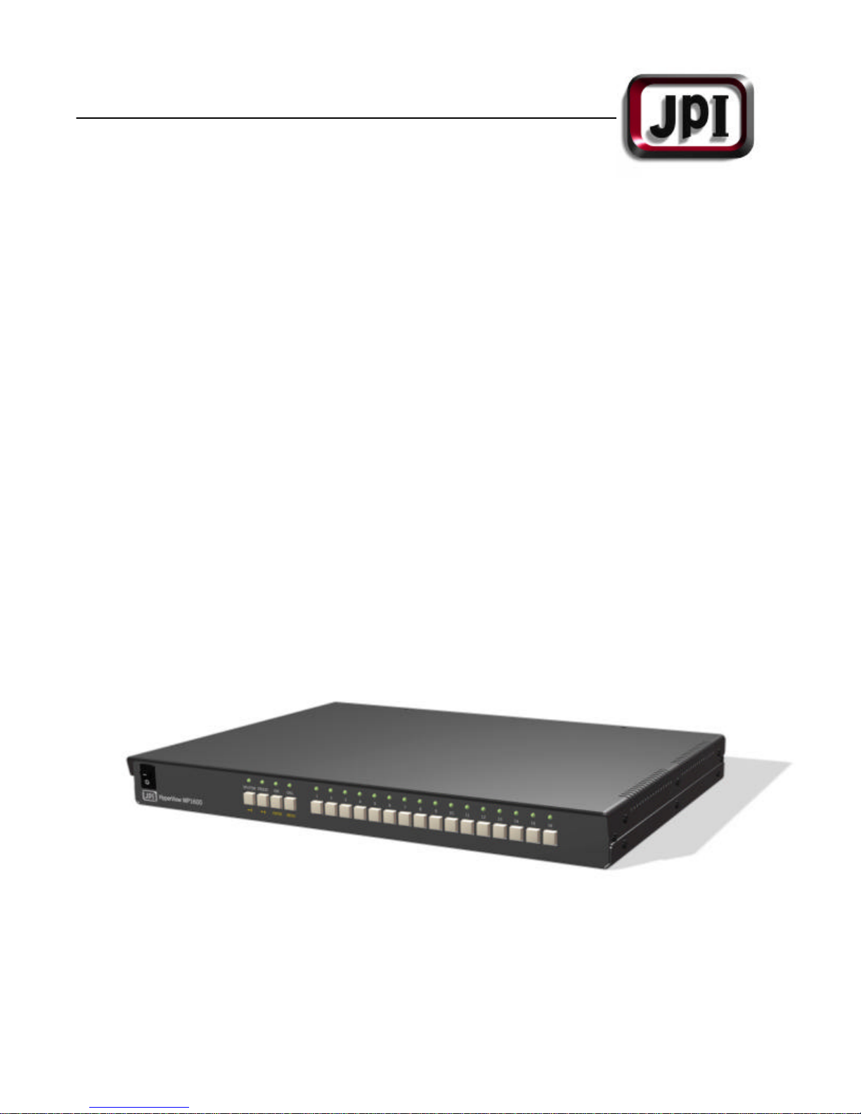
plex Multiplexer
Color/B&W Du
MP1600/BMP1600
USER’S MANUAL
Page 2
Safety Precautions
CAUTION
RISK OF ELECTRIC
CAUTION
:
TO PREVENT FIRE OR ELECTRIC
SHOCK, DO NOT EXPOSE THIS
PRODUCT TO RAIN OR MOISTURE.
SHOCK
DO NOT OPEN
TO REDUCE THE RISK OF
ELECTRIC SHOCK,
DO NOT REMOVE COVER (OR BACK).
NO USER-SERVICEABLE PARTS INSIDE.
REFER SERVICING TO QUALIFIED
SERVICE PERSONNEL.
CAUTION
ATTENTION:
POUR EVITER LES CHOCS
ELECTRIQUES, INTRODUIRE LA LAME
LA PLUS LARGE DE LA FICHE DANS LA
BORNE CORRESPONDANTE DE LA
PRISE ET POUSSER JUSQU’AU FOND.
This symbol is intended to alert the user to
the presence of un-insulated “dangerous
voltage” within the product’s enclosure that
may be of sufficient magnitude to
constitute a risk of electric shock to
persons.
This symbol is intended to alert the user to
the presence of important operating and
maintenance (servicing) instructions in the
literature accompanying the appliance.
Operating Safety
?? Use only the factory supplied (5VDC
8.0A) power adapter to operate the
system.
?? Do not try to force the system’s plug
into a power outlet. It has one blade
that is wider than the other for safety
purposes.
?? If any liquid or solid object falls into the
cabinet, unplug the system and have it
checked by a qualified technician
before operating it again.
?? Do not block the ventilation opening.
The openings keep the system from
overheating.
?? Do not install the system in a hot or
humid place, or where there is
excessive dust or vibration.
Owner’s Record
The model and serial numbers are located
at the bottom of the system. Record these
numbers in the spaces provided below.
Refer to them whenever you call technical
support regarding this product.
Model Number: _____________________
Serial Number: _____________________
1
Page 3

FCC Compliance Statement
User/Installer Caution: Your authority to
operate this FCC verified equipment could
be voided if you make changes or
modifications not expressly approved by
the party responsible for compliance to
Part 15 of the FCC rules.
Note: this equipment has been tested and
found to comply with the limits for a Class A
digital device, pursuant to Part 15 of the
FCC rules. These limits are designed to
provide reasonable protection against
harmful interference when the equipment is
operated in a commercial environment. This
equipment generates, uses, and can
radiate radio frequency energy and if not
installed and used in accordance with the
instruction manual, may cause harmful
interference to radio communications.
Operation of this equipment in a residential
area is likely to cause harmful interference
that the user will be required to correct at
his or her own expense.
This digital apparatus does not exceed the
Class A limit for radio noise emissions from
digital apparatus set out in the radio
interference regulations of Canada.
2
Page 4

Contents
Safety Precautions
FCC Compliance Statement
System Controls and Connectors
Front Panel Controls
Back Panel Connectors
Basic System Setup
Basic Operations
Full-Screen / Split-Screen Modes
Video Switching Mode
VCR Playback Mode
Call Monitor
System Configuration
Understanding Menu Buttons
Main Menu
Dwell Time
Display Formats
Alarm Settings
Activity Detection
Display – Date & Time Settings
Clock / Camera ID
Advanced Configuration
Options
Event Log / Factory Default
Video Gain
VCR Playback
Bypass Mode
Tracking Adjustment
Alarm Setup
Remote Interface
Command Set
Specifications
1
2
4
4
5
6
7
7
8
9
10
11
12
13
14
15
19
20
21
22
23
23
24
25
27
28
29
30
32
33
34
3
Page 5
System Controls and Connectors
4 5 7 8 9 1011 12 6 2 13 14 15 3 16 1
Front Panel Controls
SPLIT/SW FREEZE
VCR
CALL
ENTER
HyperView MP 1600
MENU
1 3 4 5 6 2
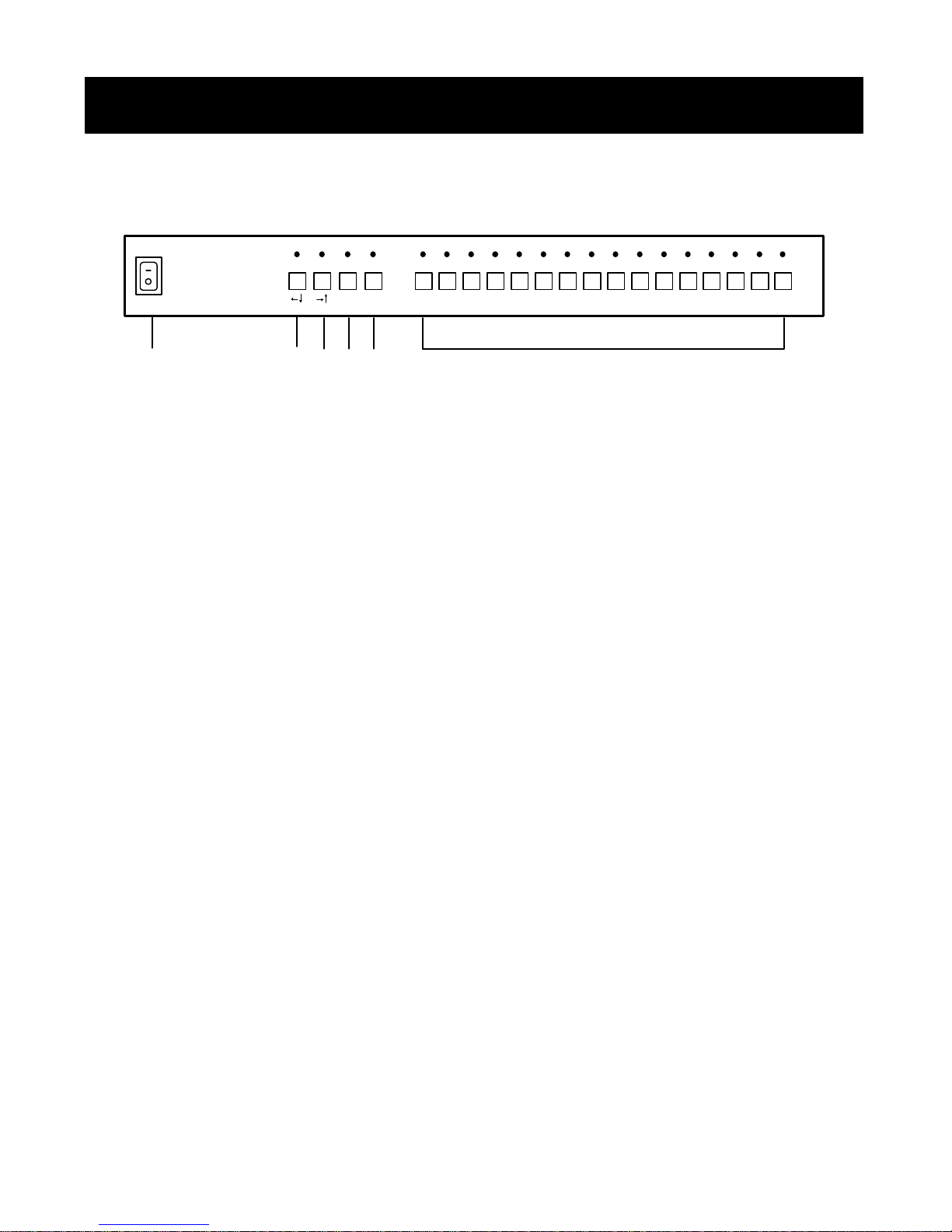
1. Power Switch p. 7
Turns the MP1600/BMP1600 on
4. FREEZE Button
Freezes the currently selected video
and off.
2. Video Selector p. 7
Selects a camera input to be
?? Function p. 12
The FREEZE button provides up and
displayed in full-screen mode to
the main monitor output.
3. SPLIT/SW Selector p. 7
Selects a preset multi-screen
5. PLAYBACK Button p. 9
Selects a VCR input to be displayed to
mode and the multi-screen/fullscreen switching mode’s main
monitor output.
?? Function p. 12
The SPLIT/SW button provides
ENTER Function p. 12
The PLAYBACK button acts as the ENTER
down and left navigation while in
user setup mode.
6. CALL Button p. 10
If this pressed for less than three
MENU Function p. 11
If pressed for longer than three
input’s main monitor output or returns to
normal video.
right navigation while in user setup
mode.
main monitor output. This button does
not affect the VCR output during duplex
operation.
button while in user setup mode.
seconds, this button will enable or
disable call monitor select mode.
seconds, the MP1600/BMP1600 will
enter user setup mode.
4
Page 6
System Controls and Connectors
1 2 3
4 5 6 7 8 9 10 11 12 13 14 15 16
1 2 3
4 5 6 7 8 9 10 11 12 13 14 15 16
Back Panel Connectors
1 2 3 5
IN
IN
OUT
OUT
7 8 4 9 10 6
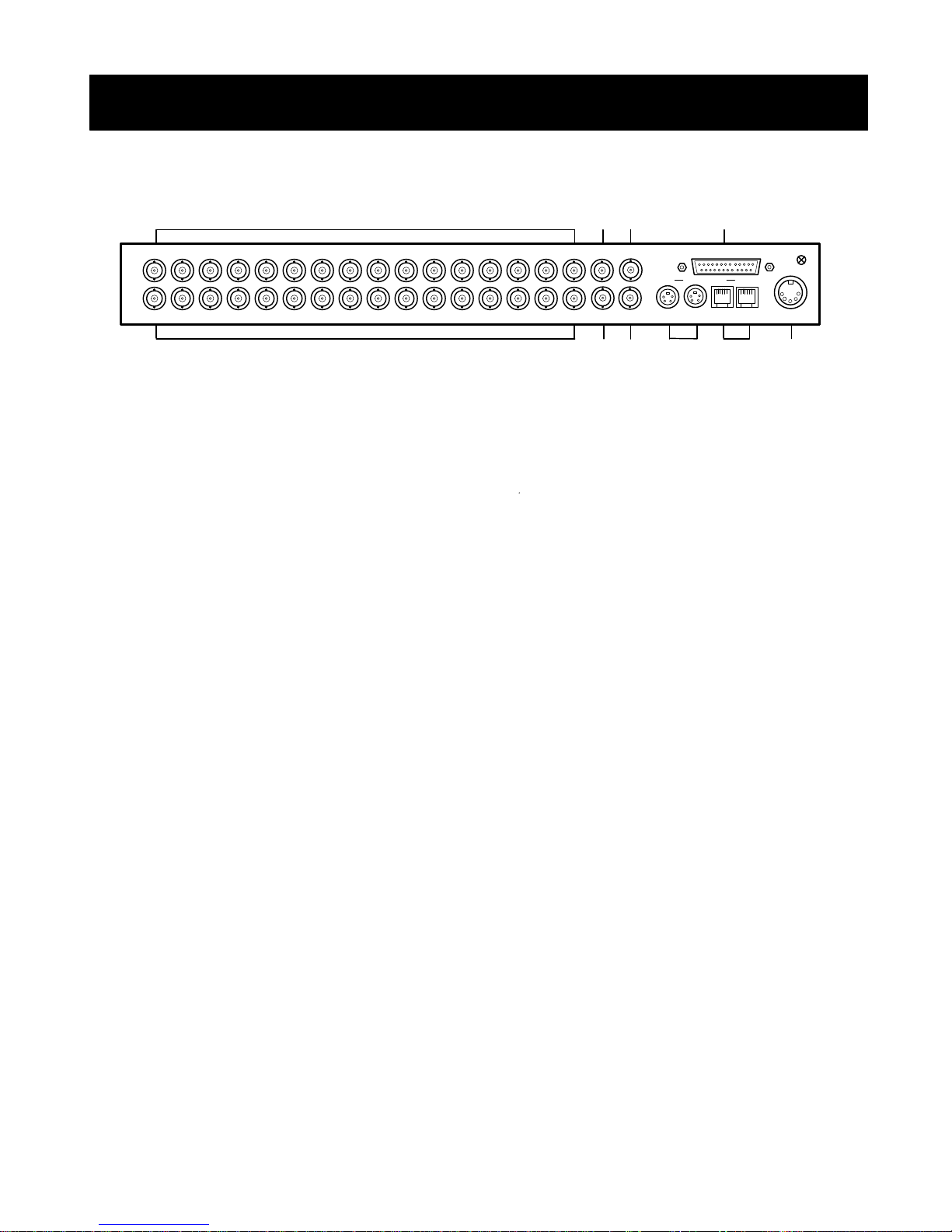
1. Video Input
Connects to the video output of up to
16 cameras.
2. Main Monitor Output
Connects to the video input of a video
monitor.
3. VCR Input
Connects to the video output of a VCR
or time-lapse recorder.
4. VCR Output
Connects to the video input of a VCR or
time-lapse recorder.
5. Alarm Input/Output
Connects to the alarm input sources
and output targets.
MONITOR VCR IN
MONITOR VCR IN
ALARM
ALARM
IN OUT IN OUT
CALL VCR OUT
CALL VCR OUT
IN OUT IN OUT
S-VIDEO VCR REMOTE I/F POWER IN
S-VIDEO VCR REMOTE I/F POWER IN
6. Power Input
Connects to the factory supplied AC/DC
power adapter.
7. Loop Thru Output
Connects to the video inputs of other
video systems.
8. Call Monitor Output
Connects to the video input of a
secondary video monitor.
9. S-Video VCR Input/Output
Connects to the S-Video output/input of
an S-Video VCR or time-lapse recorder.
10. Remote Interface Input
Connects to an MP1600/BMP1600
compatible system control device or to
a computer using an optional IBM PC
interface cable.
5
Page 7
Basic System Setup
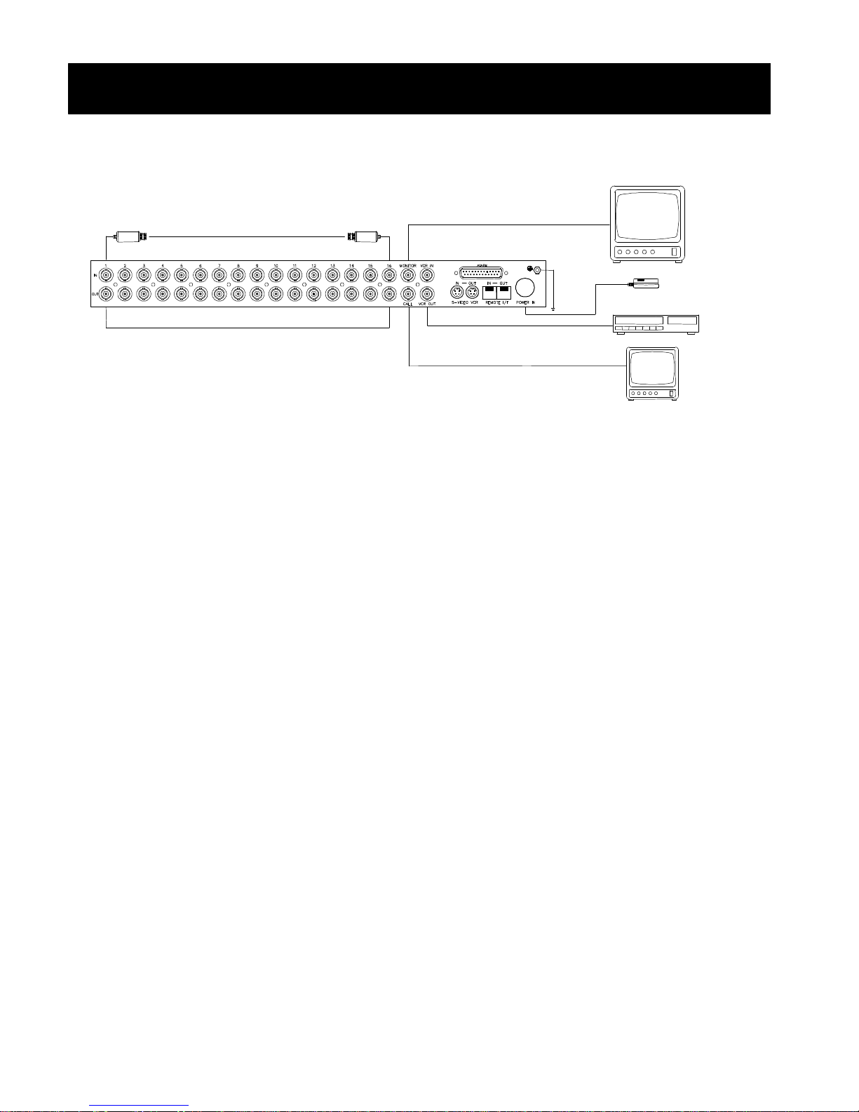
Typical System Configuration Diagram
16x Video Camera Input
16x Active Video Loop Thru
Included Equipment
?? Multiplexer Unit
?? AC/DC Power Supply
?? Operating Instructions
?? AC Power Cord
Recommended Equipment
?? Video Monitor
?? Video Tape Recorder
?? Video Cameras
?? Coaxial BNC Cables
Main Monitor
Power Supply
Time Lapse Recorder
Call Monitor
Configuration
Video Cameras
Connect up to 16 cameras to the 16 video
inputs using coaxial cable.
Main Monitor
Connect the main monitor output with the
video input connector on a video monitor
using coaxial cable.
Call Monitor
Connect the call monitor output with the
video input connector on a video monitor
using coaxial cable.
Video Tape Recorder
Connect the VCR input with the video
output on a VCR or a time-lapse tape
recorder using coaxial cable.
Connect the VCR output with the video
input on a VCR or a time-lapse tape
recorder using coaxial cable.
Power Supply
Make sure the power switch is off before
connecting the power supply. Once the
power is off, connect the factory supplied
AC power supply with the DC plug on the
MP1600/BMP1600 and an AC power
outlet.
6
Page 8
Basic Operations
Basic Buttons
FREEZE
Power Switch
SPLIT/SW
Full-Screen Mode
Video Selector
1
16
SPLIT/SW Button
SPLIT/SW
FREEZE
VCR
CALL
ENTER
MENU
Basic Buttons
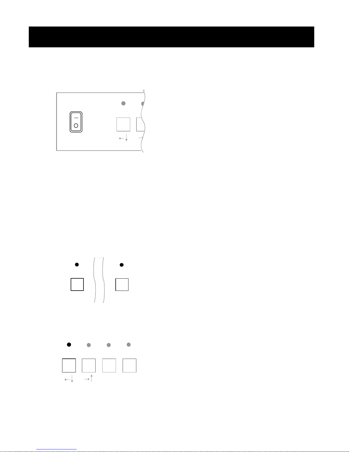
Power Switch
Turning Power On
To turn power on, press the top half of
the power switch marked “-”.
Turning Power Off
To turn the power off, press the bottom
half of the power switch marked “0”.
Caution: Make sure the power switch is
set to the off position when connecting
the AC/DC adapter to the POWER IN
connector on the MP1600/BMP1600 and
the AC outlet.
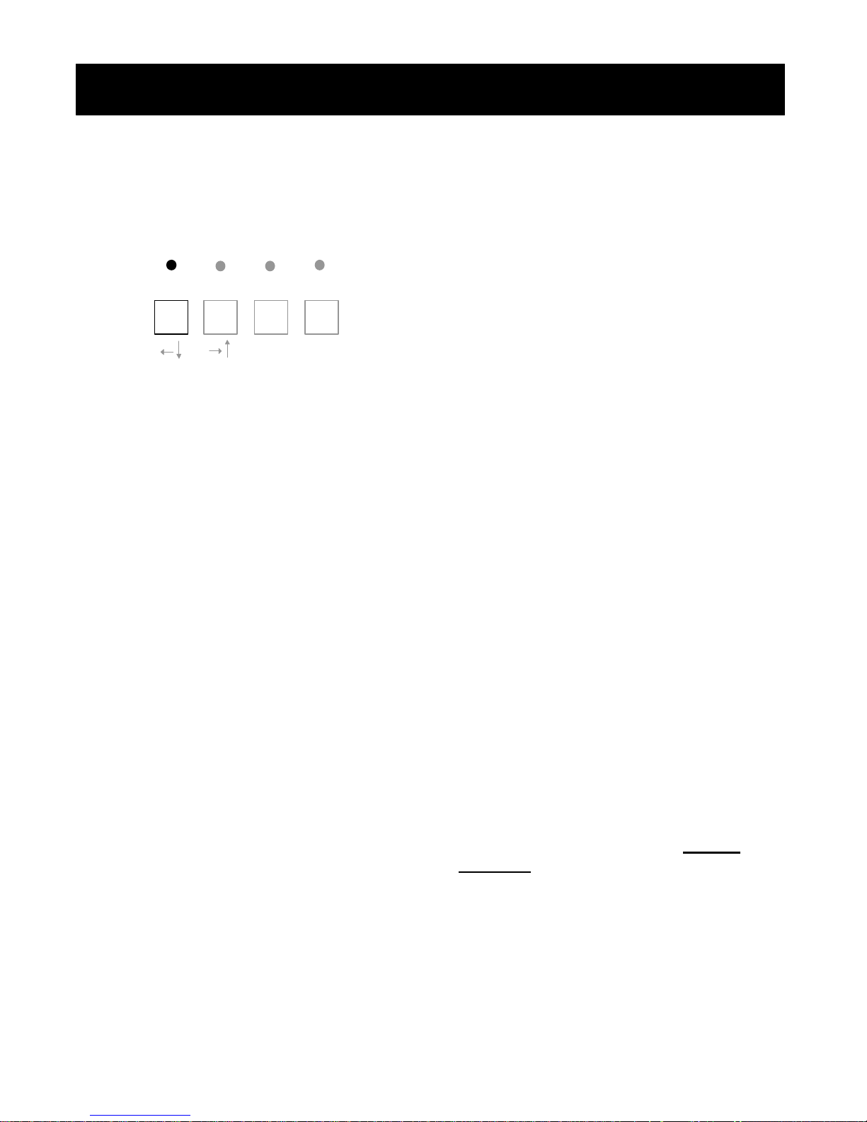
Full-Screen Mode
To select a desired camera input to be
displayed, press the button number
corresponding to the camera’s number.
For example, press button 2 to display the
input from camera 2 on the main monitor.
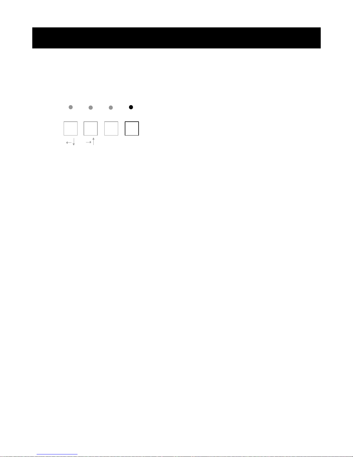
Split-Screen Mode
Press the SPLIT/SW button for less than
three seconds from any full-screen or
preset-screen mode. p. 15
7
Page 9
Basic Operations
Video Switching Mode
SPLIT/SW Button
SPLIT/SW
FREEZE
VCR
ENTER
CALL
MENU
Video Switching Mode
Multi-screen or Full-Screen
Switching Mode
Press the SPLIT/SW button for more than
three seconds to select switching mode.
Pressing the SPLIT/SW button for less than
three seconds will activate the split mode.
Activating Full-Screen Switching
Press the SPLIT/SW button while the screen
is in full-screen mode.
Activating Quad-Screen
Switching
Press the SPLIT/SW button while in quad-
screen mode (2x2). Dwell time can be set
for cameras 1, 2, 3 and 4.
Activating Preset-Mode
Switching
Press the SPLIT/SW button while in any
multi-screen mode, except quad mode
(2x2). Dwell time can be set for A, B, C and
D.
Note: The SPLIT/SW button is a preset-
screen selection button. Each time this
button is pressed, the system will switch
between each preset mode. Video switch
and customized video modes are not
available in VCR playback mode.
8
Page 10

Basic Operations
VCR Playback Mode
FREEZE
PLAYBACK Button
SPLIT/SW
VCR
CALL
ENTER
MENU
VCR Playback Mode
Entering VCR Playback Mode
Press the VCR button from any video mode
to display the VCR input (VCR IN) on the
main monitor. The VCR output will remain
unchanged.
Returning to Live Mode
Press the VCR button in VCR playback
mode to restore the mode prior to VCR
playback mode.
Note: Pressing MENU button in VCR
playback mode will select a bypass mode
(p. 28) or tracking adjustment (p. 29).
9
Page 11
Basic Operations
Call Monitor
CALL Button
SPLIT/SW
FREEZE
VCR
CALL
ENTER
MENU
Call Monitor
Activating Call Monitor
1. Press the CALL button for less than
three seconds to enter call-monitor
select mode – a press longer than three
seconds will activate the MAIN MENU.
2. The call light will blink to indicate that
the MP1600/BMP1600 is in call monitor
select mode.
3. Select the desired call monitor by
pressing the number of the desired
camera on the front panel.
4. The light will go off to indicate the
completion of the call monitor selection.
When the alarm inputs are enabled and
triggered, their corresponding video inputs
are displayed to the call monitor. In the
event of multiple alarm triggers, the call
monitor will switch between video inputs in
one-second intervals for the duration
defined in the user setup menu.
10
Page 12

System Setup Menu
User Setup Mode
MENU Function
SPLIT/SW
FREEZE
VCR
CALL
ENTER
MENU
User Setup Mode
User Setup Mode Description
The user setup menu allows for the
programming of various system operations
from within a menu-based interface. This
interface consists of an on-screen menu, a
three-button select, and modify operations.
Entering User Setup Menu
Press the MENU button for longer than
three seconds from any live video mode to
display the main setup menu on screen.
Exiting User Setup Menu
Press the MENU button for longer than
three seconds while in the user setup
menu to exit the user setup menu.
Note: The alarm will not operate while the
MP1600/BMP1600 is in user setup mode.
11
Page 13
System Configuration
FREEZE
FREEZE
FREEZE
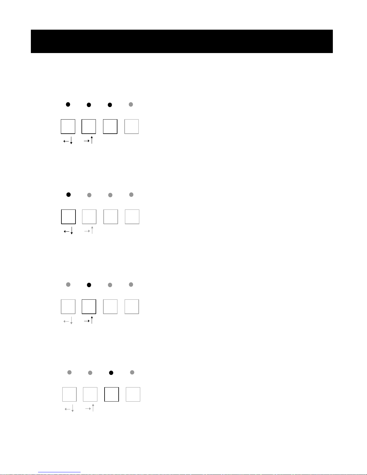
Menu Buttons
SPLIT/SW
VCR
ENTER
CALL
MENU
?? (left /down) Function
SPLIT/SW
VCR
ENTER
CALL
MENU
?? (right/up) Function
SPLIT/SW
ENTER Function
VCR
ENTER
CALL
MENU
SPLIT/SW
FREEZE
VCR
ENTER
CALL
MENU
Menu Buttons
Menu Buttons
The three buttons to the left of the MENU
button are used to control the cursors and
select items in each menu screen while the
MP1600/BMP1600 is in user setup mode.
The alternative functions of these three
buttons are marked below the buttons as
shown on the diagram.
?? (left /down) Function
This button moves the cursor to the left or
down. When an item is selected, this
button changes (or decreases) the value of
the selected item.
?? (right/up) Function
This button moves the cursor to the right or
up. When an item is selected, this button
changes (or increases) the value of the
selected item.
ENTER Function
This button selects the item that is
currently pointed to by the cursor. If this
button is pressed while an item is selected,
the current value and setting will be saved.
To discard the changes, press the MENU
button instead of the ENTER button.
12
Page 14

System Configuration
Main Menu
? DWELL TIME
DISPLAY FORMAT
ALARM
ACTIVITY DETECT
DISPLAY
CLOCK
CAMERA ID
OPTIONS
FACTORY DEFAULT
EXIT – MENU BTN
The MAIN MENU is the first screen you will
see when the MENU button is pressed for
longer than three seconds. The currently
selected sub-menu is denoted with a “? “
on the left of the sub-menu item.
Advancing to a Sub-Menu
1 Use the ?? or ?? button to move the
cursor to the item of interest. The ??
and ?? buttons are the SPLIT/SW and
FREEZE buttons, respectively, while the
MP1600/BMP1600 is in user setup
mode.
2. Select the item using the ENTER button.
The ENTER button acts as the PLAYBACK
button when the MP1600/BMP1600 is
in user setup mode.
3. A new sub-menu screen will appear.
Press the MENU button for longer than
three seconds to exit the MAIN MENU.
DWELL TIME p. 14
Causes the MP1600/BMP1600 to spend a
set amount time on each camera during
video switching mode.
DISPLAY FORMAT p.15
Allows configuration of four user
configurable split screens.
* MAIN MENU *
Main Menu
ALARM p. 19
Enables or disables the alarm inputs and
configure actions upon alarm trigger.
ACTIVITY DETECT p.20
Enable, disable, or set up activity detection
for each camera input.
DISPLAY p. 21
Allows configuration of the various onscreen displays of the date, time, and
camera identification.
CLOCK p. 22
Allows current time and date to be set.
CAMERA ID p. 22
Allows each camera to be given an
identification name of up to 12 characters
per camera.
OPTIONS p. 23
Allows configuration of various options
available on the MP1600/BMP1600.
FACTORY DEFAULT p. 24
Reset all system values to the factory
default values.
13
Page 15
System Configuration
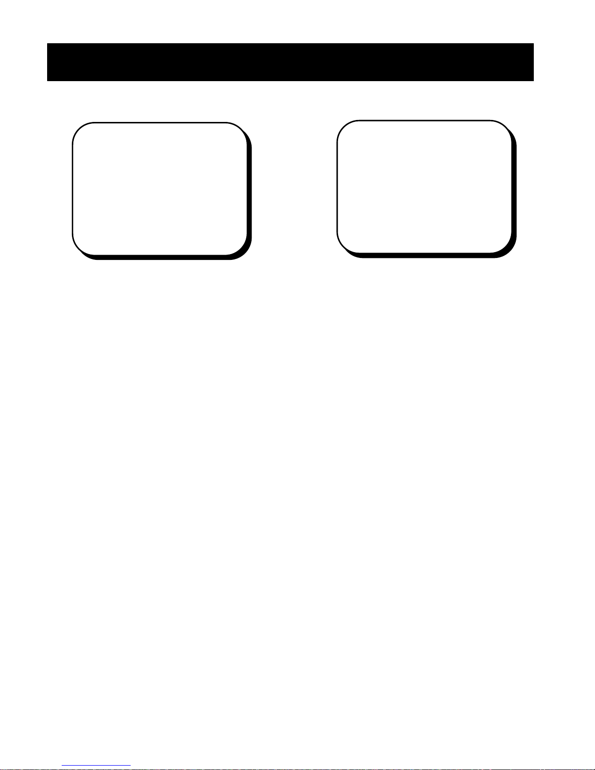
Dwell Time
The MP1600/BMP1600 is capable of
allowing each camera’s dwell time to be
set independently.
Changing Dwell Time
1. Select DWELL TIME from the MAIN MENU.
Move the cursor to the camera whose
dwell time is to be changed using the
?? or ?? button. The ?? and ??
buttons are the SPLIT/SW and FREEZE
buttons, respectively, while the MP1600
/BMP1600 is in user setup mode.
2. Select the camera to be changed using
the ENTER button. The PLAYBACK button
becomes the ENTER button when the
MP1600/BMP1600 is in user setup
mode.
3. Press the ?? button to decrease or the
?? button to increase the dwell time to
the desired time.
4. Save the setting by pressing the ENTER
button.
You may repeat steps two through five
above for each camera that requires
changes to dwell time.
Quad Mode Switching
In quad switching mode, the dwell times of
cameras 1, 2, 3 and 4 are used for the
dwell time of the 1st, 2nd, 3rd and 4th page of
the quad-screen, respectively.
*DWELL TIME*
CAMERA TIMER
1 3 SEC
2 3 SEC
3 3 SEC
4 3 SEC
5 3 SEC
6 3 SEC
7 3 SEC
8 3 SEC
NEXT PAGE
RETURN
Dwell Time
MODE TIMER
A 5 SEC
B 5 SEC
C 5 SEC
D 5 SEC
NEXT PAGE
RETURN
Preset Mode Switching
In preset mode, dwell time can be set four
different ways and then saved in presets A,
B, C, or D.
See page 15 for more details on different
split-screen modes.
*DWELL TIME*
14
Page 16
System Configuration
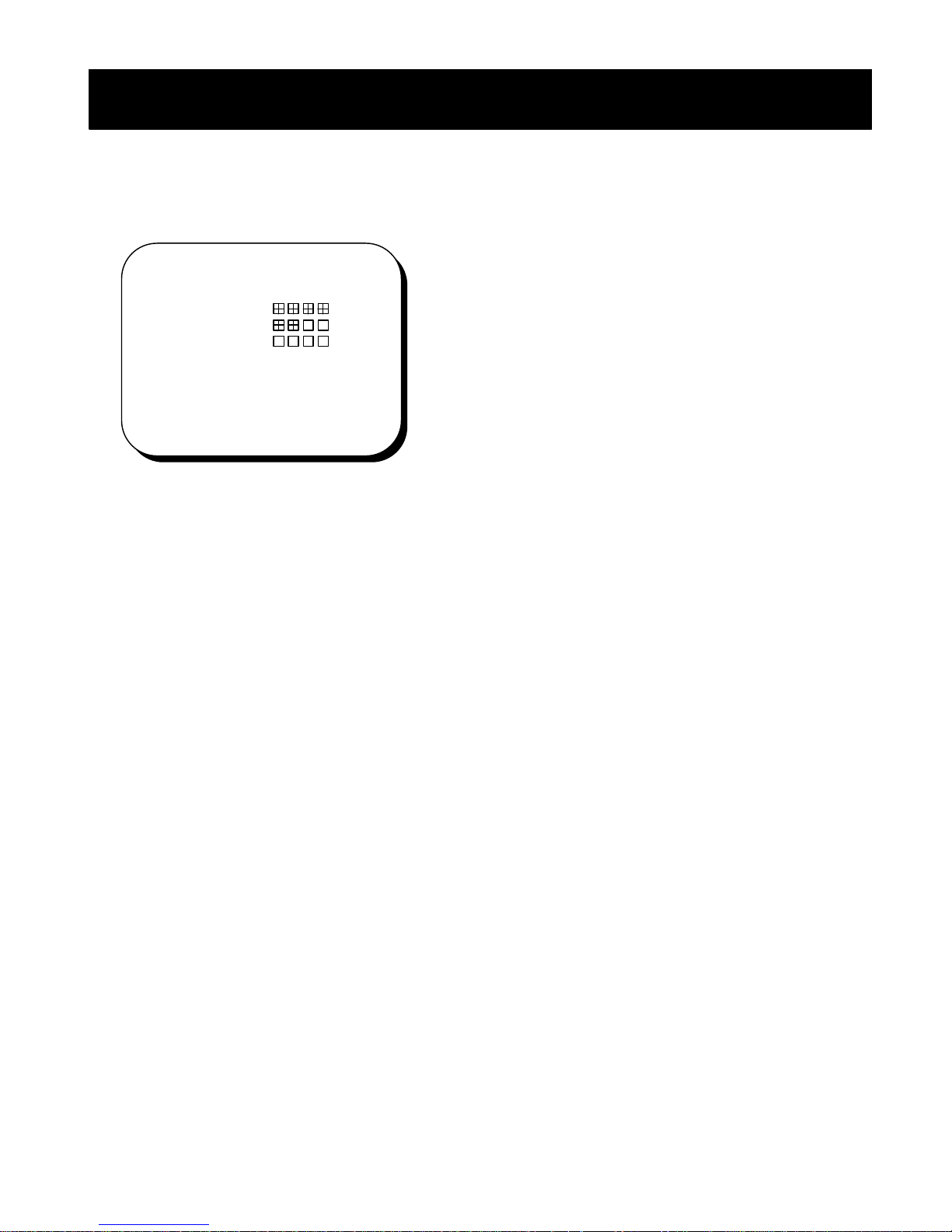
Display Formats
The MP1600/BMP1600 is capable of
having four different preset screens
configured.
Each mode setting can be configured by
the user.
Once you have set up the preset screens,
you can select the desired preset screen
by pressing the SPLIT/SW button.
* DISPLAY FORMAT *
MODE SETTING
1
2
3
4 OFF
NEXT PAGE
SAVE MODE OFF
RETURN
Display Formats
Display Save Mode
Save mode allows you to save the last
screen you were in before turning off the
system.
Saving a Mode
1. Select SAVE MODE from DISPLAY FORMAT.
2. Use the ?? or ?? button to change the
setting to ON or OFF. The ?? and ??
buttons are the SPLIT/SW and FREEZE
buttons, respectively, while the
MP1600/BMP1600 is in user setup
mode.
3. Save the setting by pressing the ENTER
button. The PLAYBACK button becomes
the ENTER button when the
MP1600/BMP1600 is in user setup
mode.
15
Page 17
System Configuration
?
?
OFF
QUAD
?
?
# DISPLAY FORMAT #
MODE SETTING
Quadrant A B C D
1
2
3
4
Display Formats
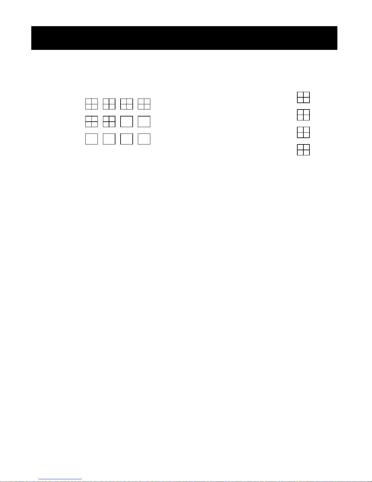
Mode
The numbers represent the preset modes.
The four mode settings are broken down
into quadrants A, B, C and D.
Changing the Mode Setting
1. Use the ?? or ?? button to move the
cursor to the mode that is to be
changed. The ?? and ?? buttons are
the SPLIT/SW and FREEZE buttons,
respectively, while the
MP1600/BMP1600 is in user setup
mode.
2. Select the mode using ENTER button.
The ENTER button is the same as the
PLAYBACK button when the
MP1600/BMP1600 is in user setup
mode.
Display Formats
# DISPLAY FORMAT #
QUAD FORMAT
Screen Sizes
The MP1600/BMP1600 is capable of
allowing each camera’s screen size (1/4,
1/8 or 1/16) to be set independently.
Changing Screen Mode
1. Select MODE from DISPLAY FORMAT.
2. Use the ?? or ?? button to move the
cursor to quadrant, shown above, to be
changed. The ?? and ?? buttons are
the SPLIT/SW and FREEZE buttons,
respectively, while the
MP1600/BMP1600 is in user setup
mode.
3. Select the quadrant using the ENTER
button. The ENTER button is the same
as the PLAYBACK button when the
MP1600/BMP1600 is in user setup
mode.
4. Press ?? or ?? button to change to
the desired FORMAT setting.
5. Save the setting by pressing the ENTER
button.
You may repeat steps two through five
above for each quadrant that requires
changes to its screen setting.
A
B
C
D
QUAD
QUAD
QUAD
16
Page 18
11 12 15 16
System Configuration
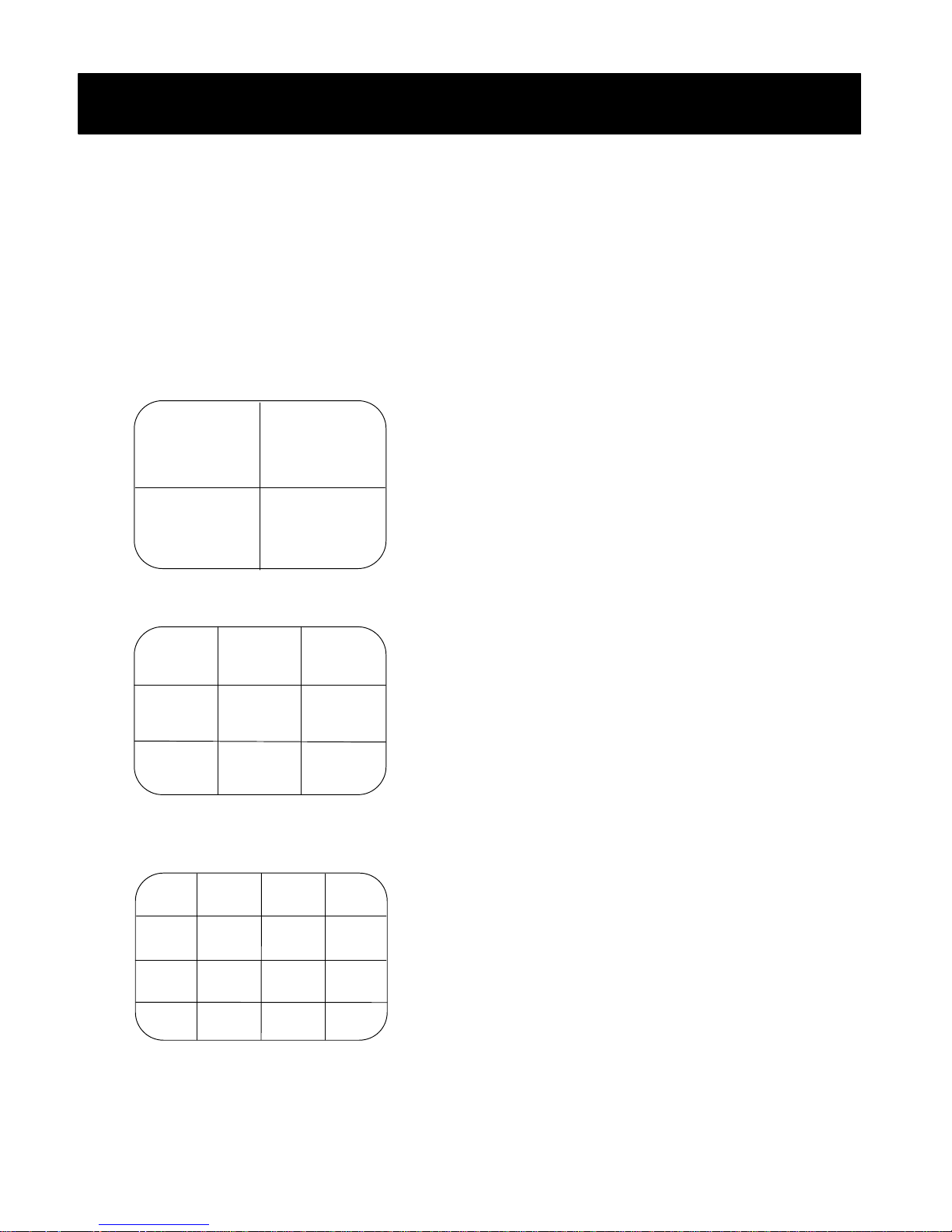
Standard Split-Screen Layouts
2x2
1
9
3x3
1 2 5
3 4 7
9 10 13
4x4
1 2 5 6
3 4 7 8
9 10 13 14
5
13
Display Formats
Standard Split-Screen Types
The MP1600/BMP1600 allows the
selection and configuration of up to four
standard custom screen displays. You may
select the desired screen by pressing the
SPLIT/SW button, which will allow you to
toggle through your four preset-screen
settings.
2x2 Mode
Four-camera mode allows you to view
cameras 1, 5, 9 and 13.
3x3 Mode
Nine-camera mode allows you to view
cameras 1, 2, 3, 4, 5, 7, 9, 10 and 13.
4x4 Mode
Sixteen-camera mode allows you to view
all sixteen cameras.
17
Page 19
QUADRANT D
QUADRANT B
QUADRANT C
QUADRANT A
System Configuratio
n
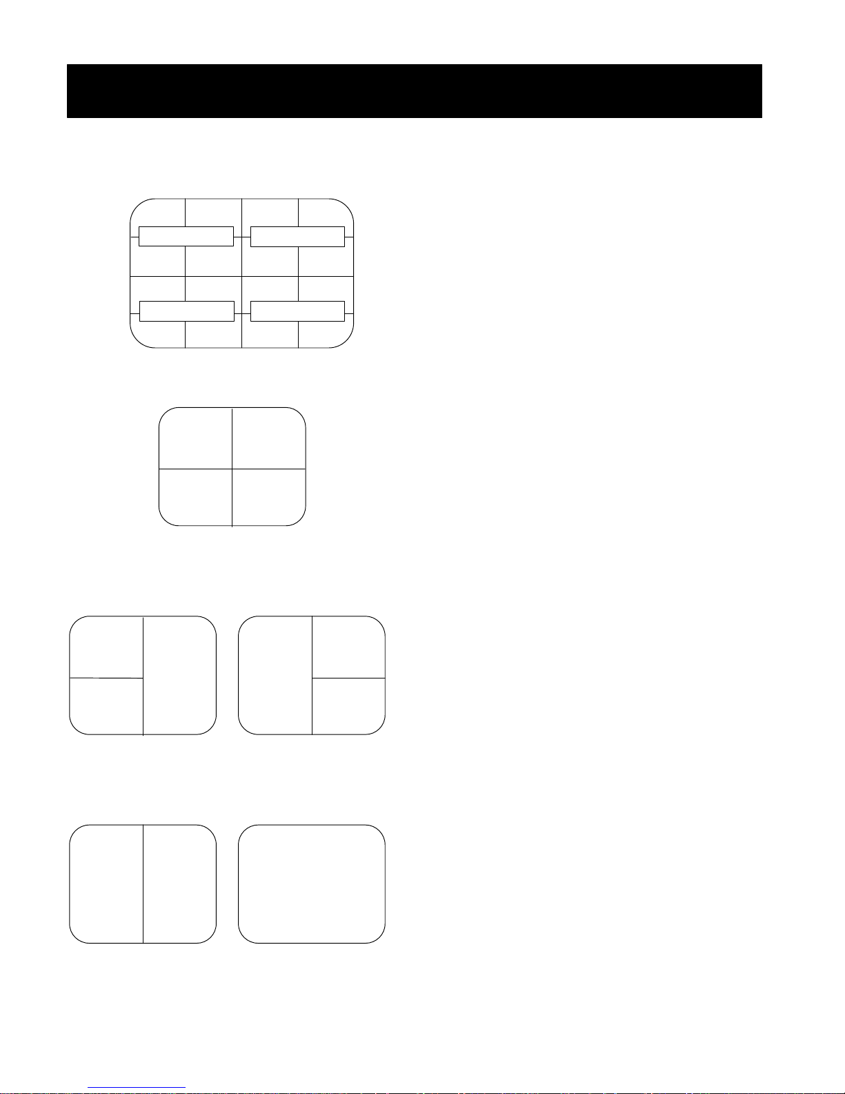
Custom Split-Screen Layouts
Quadrant Layout
Triple A Screen Triple B Screen
1
3
Dual Screen Full Screen
1
1 2 5 6
3 4 7 8
9 10 13 14
11 12 15 16
Quad Screen
1
3
2
2
2
4
2
1
4
Custom Split-Screen Types
Custom Split-Screen Types
The MP1600/BMP1600’s screen is split up
into four separate quadrants (A, B, C and
D). Each quadrant can be split up to
display up to four cameras in the formats
described below. This will allow you to fully
configure a multi-screen display.
Quad Screen
Each of the four camera inputs will be
displayed in one of the four quadrants.
Triple A Screen
Cameras 1 (5, 9 or 13) and 3 (7, 11 or 15)
are displayed in one of the two left
quadrants while the right half of the camera
2 (6, 10 or 14) input is displayed on the
right half of the screen.
Triple B Screen
Cameras 2 (6, 10 or 14) and 4 (8, 12 or 16)
are displayed in one of the two right
quadrants while the left half of the camera
1 (5, 9 or 13) input is displayed on the left
half of the screen.
Dual Screen
Cameras 1 (5, 9 or 13) and 2 (6, 10 or 14)
are displayed in the left and the right half
of the screen, respectively.
Full Screen
Camera 1 (5, 9 or 13) is displayed in full.
18
Page 20

System Configuration
Alarm Settings
* ALARM *
CAMERA ALARM
1 OFF
2 OFF
3 OFF
4 OFF
5 OFF
6 OFF
7 OFF
8 OFF
NEXT PAGE
TIME 15 SEC
RETURN
Each alarm input to the MP1600/BMP1600
can be configured independently.
Changing Alarm Settings
1. Select ALARM from MAIN MENU.
2. Use the ?? or ?? button to move the
cursor to the camera whose alarm
setting is to be changed. The ?? and
?? buttons are the SPLIT/SW and
FREEZE buttons, respectively, while the
MP1600/BMP1600 is in user setup
mode.
3. Select the desired camera using the
ENTER button. The ENTER button is the
same as the PLAYBACK button when the
MP1600/BMP1600 is in user setup
mode.
4. Press ?? or ?? button to change the
alarm setting.
5. Save the setting by pressing the ENTER
button.
You may repeat steps two through five
above for each camera that requires
changes to the alarm set up.
Select NEXT PAGE to choose cameras 9
through 16.
Alarm Settings
Available Alarm Settings
OFF Alarm is off, so the
MP1600/BMP1600 will not
respond to the alarm inputs.
BEEP The MP1600/BMP1600 will
sound an alarm, a beeping
noise, to alert when it is triggered
by an alarm input.
VIDEO The MP1600/BMP1600 will
display a magenta frame around
the affected video on both the
MAIN MONITOR and the VCR OUT
when it is triggered by an alarm
input.
V+B The MP1600/BMP1600 will
sound an alarm, a beeping
noise, and display a message on
the monitor when it is triggered
by an alarm input.
19
Page 21

System Configuration
Activity Detection
* ACTIVITY DETECT *
CAMERA DETECT
1 OFF
2 OFF
3 OFF
4 OFF
5 OFF
6 OFF
7 OFF
8 OFF
NEXT PAGE
RETURN
Each alarm input to the MP1600/BMP1600
can be configured independently by
changing its respective camera activity
detection setting.
Changing Activity Detection
Settings
1. Select ACTIVITY DETECT from the MAIN
MENU.
2. Use the ?? or ?? button to move the
cursor to the camera whose activity
detection setting is to be changed. The
?? and ?? buttons are the SPLIT/SW
and FREEZE buttons, respectively, while
the MP1600/BMP1600 is in user setup
mode.
3. Select the desired camera using the
ENTER button. The ENTER button is the
same as the PLAYBACK button when the
MP1600/BMP1600 is in user setup
mode.
4. Press ?? or ?? button to change the
camera’s alarm setting.
5. Save the setting by pressing the ENTER
button.
You may repeat steps two through five
above for each camera that requires
changes to set up an alarm.
Select NEXT PAGE to choose cameras 9
through 16.
Activity Detection
Available Detection Settings
OFF
Activity detect is off, so the
MP1600/BMP1600 will not respond to any
activity.
MIN TO MAX
The lower the number the more movement
is required to activate the Activity
Detection. Determine the desired setting by
experimenting with different degrees of
sensitivity.
Note: The alarm setting must be active on
its corresponding camera in order for
activity detection to work. For example, if
you wish to have activity detection on
camera 1, select the setting under the
ACTIVITY DETECT MENU for camera 1 and
also select the setting under the ALARM
MENU for camera 1.
20
Page 22

System Configuration
Display Settings
? DATE MM/DD/YY
TIME HH:MM:SS
SPLIT ID ON
FULL ID ON
REC ID ON
REC TIME ON
RETURN
Changing Display Settings
1. Select DISPLAY from the MAIN MENU.
2. Use the ?? or ?? button to move the
cursor to the item whose setting is to be
changed. The ?? and ?? buttons are
the SPLIT/SW and FREEZE buttons,
respectively, while the MP1600/
BMP1600 is in user setup mode.
3. Select the item using the ENTER button.
The ENTER button is the same as the
PLAYBACK button when the MP1600/
BMP1600 is in user setup mode.
4. Use the ?? or ?? button to change
the setting.
5. Save the setting by pressing the ENTER
button.
*DISPLAY *
FORMAT
Display - Date & Time Settings
Available Date Settings
OFF No date information is
displayed.
MM/DD/YY Month/Day/Year
DD/MM/YY Day/Month/Year
DD/MM Day/Month
Available Time Settings
OFF No time information is
displayed.
HH:MM Hour:Minute
HH:MM:SS Hour:Minute:Second
SPLIT ID Enable or disable the display
of the camera number in
split-screen mode.
FULL ID Enable or disable the display
of camera identification in the
full-screen or full-screen
switching modes.
REC ID Enable or disable the display
of camera identification in
VCR recording.
REC TIME Enable or disable the display
of the date and time in VCR
recording.
21
Page 23
System Configuration
Clock / Camera ID
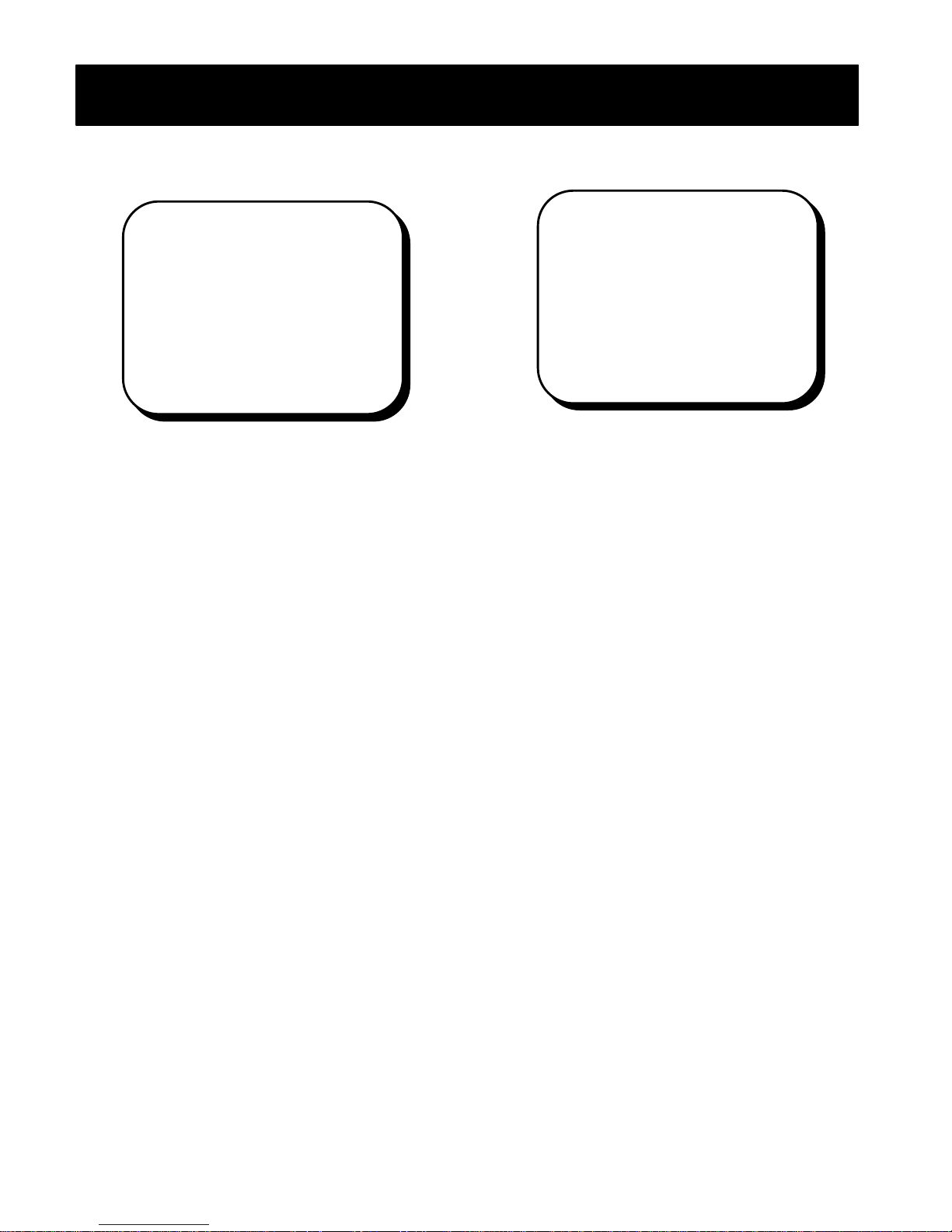
System Clock
? DATE 05/01/00
TIME 00:00:00
RETURN
Setting the Current Date and
Time
1. Select CLOCK from the MAIN MENU.
2. Use the ?? or ?? button to move the
cursor to the DATE or TIME whose
setting is to be changed. The ?? and
?? buttons are the SPLIT/SW and
FREEZE buttons, respectively, while the
MP1600/BMP1600 is in user setup
mode.
3. Select the item using the ENTER button.
The ENTER button is the same as the
PLAYBACK button when the MP1600/
BMP1600 is in user setup mode.
4. The currently selected field will blink.
5. Press the ?? or ?? button to change
the value.
6. Confirm the setting by pressing the
ENTER button. The cursor will
automatically advance to the next field.
7. Repeat steps 4 and 5 until the last field
is reached.
The new settings will be saved, and they
will take effect when the last field is
entered.
* CLOCK *
Camera ID
CAMERA ALARM
1 CAM 1
2 CAM 2
3 CAM 3
4 CAM 4
5 CAM 5
6 CAM 6
7 CAM 7
8 CAM 8
NEXT PAGE
RETURN
The MP1600/BMP1600 provides up to
twelve characters for camera identification.
Changing the Camera ID
1. Select CAMERA ID from the MAIN MENU.
2. Use the ?? or ?? button to move the
cursor to the camera whose
identification is to be changed. The ??
and ?? buttons are the SPLIT/SW and
FREEZE buttons, respectively, while the
MP1600/BMP1600 is in user setup
mode.
3. Select the desired camera using the
ENTER button. The ENTER button is the
same as the PLAYBACK button when the
MP1600/BMP1600 is in user setup
mode.
4. The currently selected field will blink.
5. Press the ?? or ?? button to change
the character.
6. Confirm the settings by pressing the
ENTER button. The cursor will
automatically advance to the next field.
7. Repeat steps five and six until the last
field is reached.
The new settings will be saved and will
take effect when the last field is entered.
Select NEXT PAGE to change cameras 9
through 16.
* CAMERA ID*
22
Page 24

Advanced Configuration
Options
Menu Lock
Menu lock allows you to lock the MAIN
MENU. Once the menu is locked, the
system password must be used to access
the MAIN MENU.
Note: The MP1600/BMP1600 has a preselected password: 1227.
To access the locked MAIN MENU, enter the
system password using the numbers on
the buttons normally used for camera
selection.
VTR Input
Select the input and output type of the
VCR or time-lapse recorder. This can be
set to S-Video or composite.
V Loss
Select the type of alarm to be sounded in
case of a loss of video, OFF, BEEP, or V-B.
V Gain
Reset or adjust input video gains.
MENU LOCK OFF
VTR INPUT COMPOSITE
V LOSS OFF
V GAIN NORMAL
HYPER REC 16
EVENT LOG
RETURN
* OPTIONS *
Options
M
Hyper Recording
Hyper recording allows you to select the
number of cameras you wish to record.
This will allow you to take advantage of the
faster recording speed and better quality of
nine-camera recording. You may view as
many cameras as you wish in LIVE mode,
but the MP1600/BMP1600 will only record
the pre-selected number of cameras.
16 CAMERAS MODE (default mode)
Record – All 16 cameras are recorded.
Playback – All 16 cameras are displayed.
9 CAMERAS MODE
Record – Only 9 cameras, numbers
1,2,3,4,5,7,9,10 and 13, will be recorded.
Playback – Displayed in 3x3 mode with
nine recorded cameras, the only option in
the SPLT/SW mode. Press the SPLT/SW
button to select between dual and quad
pages. Press camera number to bring up
full-screen mode.
EVENT LOG
Reset or review event log.
23
Page 25

Advanced Configuration
Event Log / Factory Default
Event Log
SYSTEM EVENT ON
ALARM INPUT ON
ACTIVITY DETECT ON
DISPLAY LOG
CLEAR LOG
RETURN
System Event
When enabled, the times when the system
is turned on and off and when the menu is
accessed are recorded in the log.
Alarm Input
When enabled, alarms triggered by the
external alarm inputs are recorded in the
log.
Activity Detect
When enabled, alarms triggered by activity
detection are recorded in the log.
Display Log
Displays the event log on screen. Use the
?? and ?? buttons to scroll. The ?? and
?? buttons are the SPLIT/SW and FREEZE
buttons, respectively, while the
MP1600/BMP1600 is in user setup mode.
Clear Log
Clear all events in the log.
The event log is capable of recording up to
256 events. Once 256 events are reached,
the oldest log entry is overwritten when
new events are logged.
* EVENT LOG *
Factory Default Reset
Setting to Factory Default
MP/BMP 1600
Resetting System Values to
Factory Defaults
1. Move the cursor to FACTORY DEFAULT in
the MAIN MENU.
2. Select FACTORY DEFAULT by pressing
the ENTER button. The ENTER button is
the same as the PLAYBACK button when
the MP1600/BMP1600 is in user setup
mode.
3. The menu screen will disappear
momentarily and then reappear. When
this is complete, the factory default
settings are restored.
Date, time, and event log settings will not
be affected by execution of factory default.
24
Page 26
ADJUST
Advanced Configuration
Video Gain Control
Gain Modes
Normal: Automatic gain control of the input
video is enabled. This mode should be
used when normal video input signals are
fed to the MP1600/BMP1600.
Manual: Automatic gain control is disabled.
The previous settings for the gain are used
to increase or decrease the input video
signal.
Reset: Reset the settings for the gain to
the factory default values. Use of this
option is recommended the first time
MANUAL gain mode is enabled or when the
manual adjustment goes out of control.
After resetting the gain, the
MP1600/BMP1600 will automatically
proceed to the ADJUSTMENT screen for
review of the settings. See page 26 for
details.
Adjust: Enter the ADJUSTMENT screen to
adjust the gain for each video input. See
page 26 for details.
V GAIN
Video Gain
Proper installation and use of standard
video equipment will maximize the
capabilities of the MP1600/BMP1600.
However, in certain installations or with the
use of non-standard video equipment, it is
possible the MP1600/BMP1600 will receive
unusually strong or weak input signals. In
most conditions, the MP1600/BMP1600
can stabilize video input signals. In
extreme conditions, it may be necessary to
manually adjust the video input signals
using the manual video gain control.
Entering Video Gain Control
Setup
1. Move the cursor to V Gain in the
options menu. Select V Gain by
pressing the ENTER button. The
ENTER button is the same as the
PLAYBACK button when the MP1600/
BMP1600 is in user setup mode.
2. The previously selected mode will
flash.
3. Use the ?? or ?? button to select
one of the four available modes.
The ?? and ?? buttons are the
SPLIT/SW and FREEZE buttons,
respectively, while the MP1600/
BMP1600 is in user setup mode.
25
Page 27

Advanced Configuration
Video Gain Adjustment
Screen
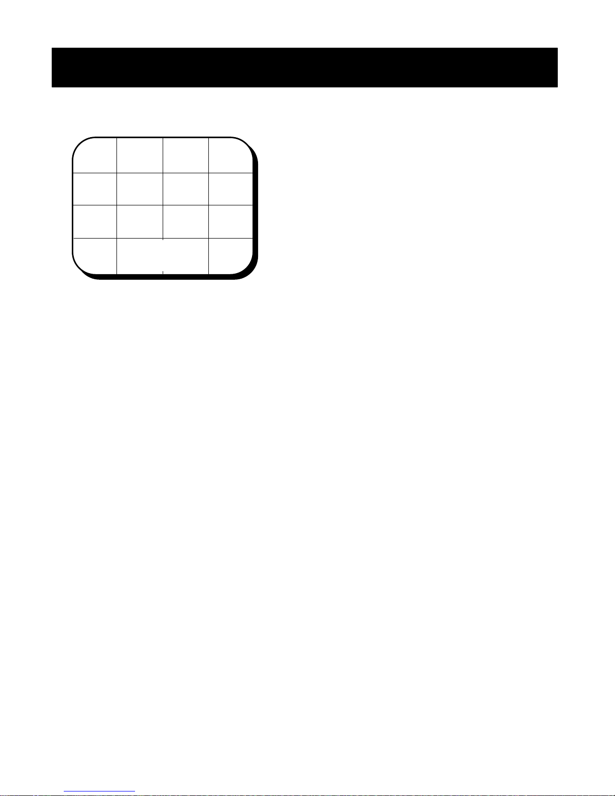
When RESET or ADJUST mode are selected,
the MP1600/BMP1600 will enter the
ADJUSTMENT screen. In the ADJUSTMENT
screen, 16-camera split-screen (4x4) mode
will be displayed. The currently selected
video input for adjustment will be boxed in
cyan.
Selecting the Video Input for
Adjustment
Select the desired camera to adjust
using the video selector buttons on the
front panel. The selected video will be
boxed in cyan.
Adjusting the Gain
Use the ?? or ?? button to increase
or decrease the gain. The ?? and ??
buttons are the SPLIT/SW and FREEZE
buttons, respectively, while the
MP1600/BMP1600 is in user setup
mode.
Exiting the Adjustment Screen
Press ENTER or MENU button to exit.
These are the PLAYBACK and CALL
buttons, respectively, while the
MP1600/BMP1600 is in user setup
mode.
Note: These adjustments affect both the
main video output and VCR output. Make
sure to check for the proper operation of
VCR output when MANUAL mode is
selected.
Video Gain
26
Page 28
VCR Playback
FREEZE
PLAYBACK Button
SPLIT/SW
Video Selector
1
Split-Screen Selector
SPLIT/SW
FREEZE
VCR
ENTER
16
VCR
ENTER
CALL
MENU
CALL
MENU
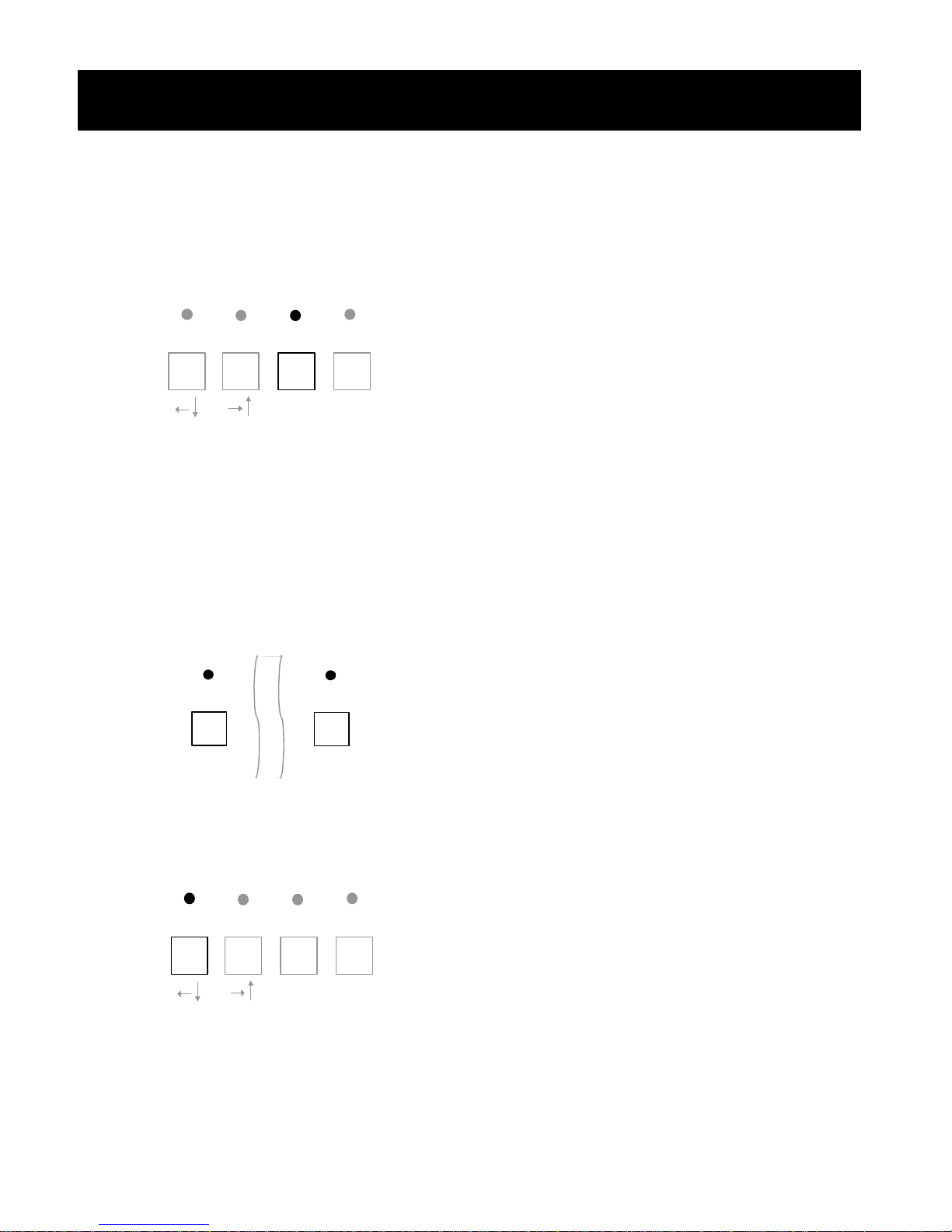
VCR Playback Mode
Enabling VCR Playback
Press the PLAYBACK button from any video
mode. The VCR input (VCR IN) will be
displayed on the main monitor. The VCR
output will remain unchanged.
Returning to Live Mode
Press the PLAYBACK button in VCR
playback mode. The mode prior to VCR
playback mode will be restored.
Note: The MENU button in VCR playback
mode will select a VCR bypass (see p. 28)
or a VCR tracking adjustment (see p. 29).
Full-Screen Mode
To select a desired camera input to be
displayed, press the button number
corresponding to the camera’s number.
For example, press button 2 to display the
input from camera 2 on the main monitor.
Split-Screen Mode
Press the SPLIT/SW button for less than
three seconds from any full-screen or split
screen mode.
27
Page 29

VCR Playback
Bypass Mode
Bypass Mode
BYPASS
The MP1600/BMP1600 has a unique
feature that allows the monitoring of VCR
input without de-multiplexing. This feature
is useful for verifying correct operation of
VCR output on the MP1600/BMP1600 and
for diagnosing VCR playback related
problems.
Entering Bypass Mode
1. While in VCR playback mode, press the
CALL button for less than three
seconds. The word “BYPASS” will
appear on the bottom of the screen.
2. There are three bypass modes:
interlaced mode, odd only mode, and
even only mode.
3. Each press of the MENU button will
change the mode to the next mode and
will return to the normal VCR playback
mode after the last bypass mode.
Monitoring VCR Recording
By entering VCR bypass mode, the actual
video images being recorded by the
MP1600/BMP1600 can be monitored. Due
to the fact that the MP1600/BMP1600
records either 9 or 16 cameras at once by
switching rapidly from one camera to the
next, the video images displayed in this
mode may not be recognizable. This is
normal.
Diagnosing VCR Playback
Problems
Most VCR playback problems arise
because of improper system installation or
because of VCR problems. By entering
VCR bypass mode, the video images
recorded by the VCR can be observed.
VCR Menu Setup
The video signal generated by VCR in the
VCR setup menu may not be recognized
by the de-multiplexing circuitry of
MP1600/BMP1600. To view video
produced by the VCR setup menu, use
VCR bypass mode.
28
Page 30

VCR Playback
Tracking Adjustment
Tracking Adjustment
The MP1600/BMP1600 allows you to
enhance the tracking capabilities of certain
VCRs that do not conform to standard
video.
Entering Tracking Adjustment
Press the MENU button from any VCR
playback mode. “ADJUST FOR VCR” will
appear on the bottom of screen adjustment
mode.
Enhancing the Tracking
1. Use the ?? or ?? button to adjust the
tracking while the MP1600/BMP1600 is
in user setup mode.
2. Confirm the settings by pressing the
ENTER button.
3. Press EXIT button to exit VCR Tracking
Adjustment Mode.
The new setting will be saved and take
effect immediately.
ADJUST
FOR VCR
Tip: If you see a line or noise between
screens during playback, use the ?? or
?? button while in the VCR TRACKING
ADJUSTMENT mode to adjust the tracking
and line up the screens. This will ensure
the best possible playback quality.
29
Page 31
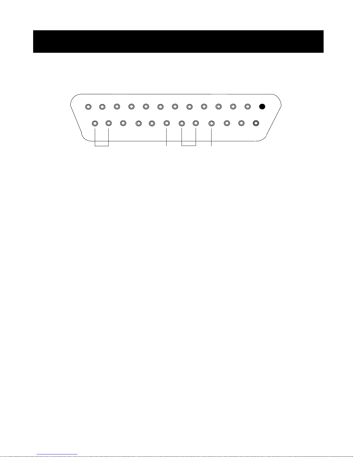
The MP1600/BMP1600 provides an interface to external alarm inputs and outputs through a
ar panel. Authorized dealers supply a mating connector to
can be either a normally open or a normally closed type.
The alarm input type is automatically detected by the
Ground. Should be connected to the ground reference of
an be connected to a
lapse recorder alarm input that requires a
Normally Closed alarm output. This can be connected to
lapse recorder alarm input that requires a
Alarm Setup
#1
#13
#25
GND N.O. COM N.C.
Alarm Setup and Installation
#14
25-pin D-SUB connector on the re
this for the MP1600/BMP1600.
1 to 16 Alarm inputs for each corresponding camera. Each alarm
MP1600/BMP1600.
GND
the alarm detection device.
N.O. Normally Open alarm output. This c
VCR or timenormally open alarm input.
N.C.
VCR or timenormally closed alarm input.
COM COMmon alarm output. This can be connected to a VCR or
time-lapse recorder alarm common port.
Pin Definitions
30
Page 32
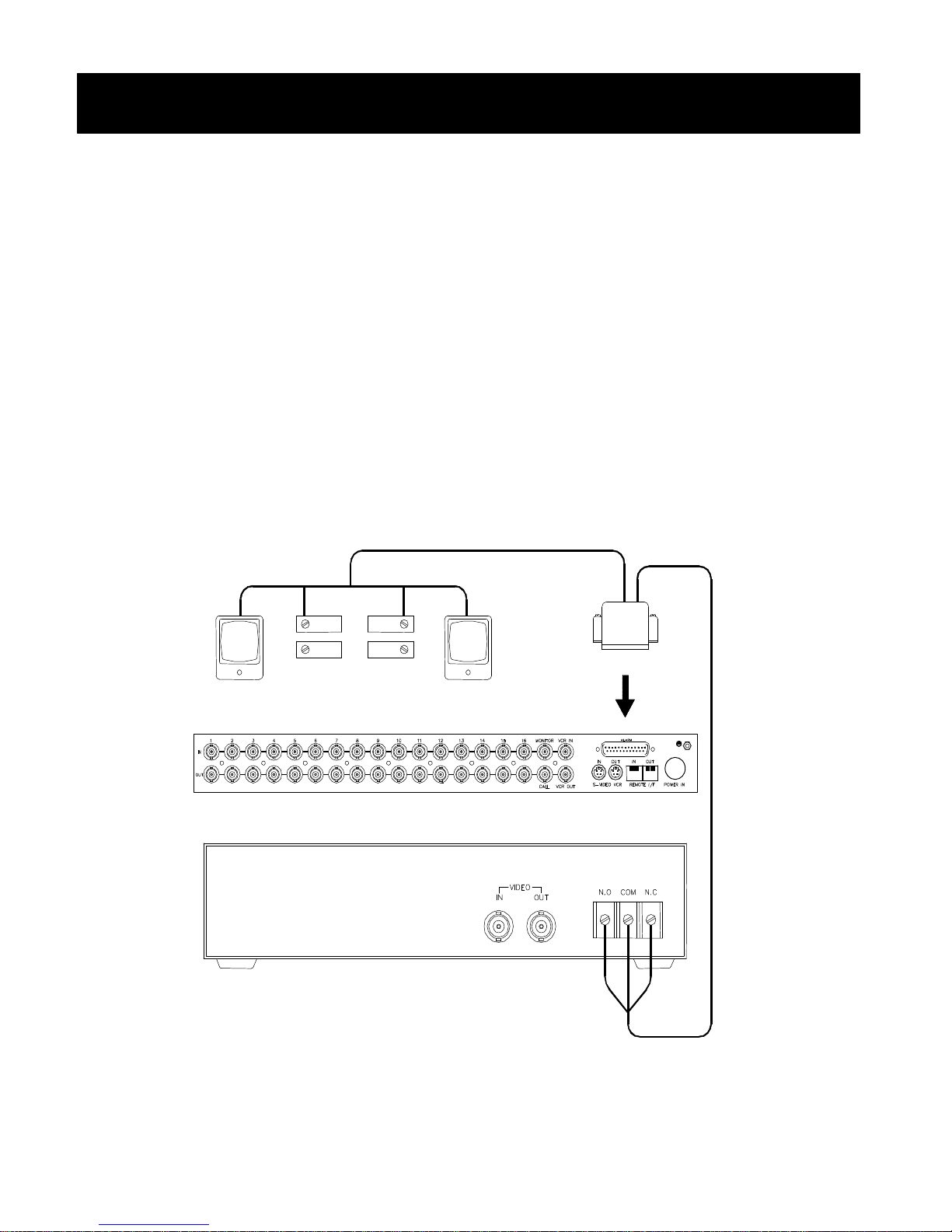
detect the alarm input type;
therefore, either a normally open or normally closed type of alarm device can be used
with the MP160
Note: Because the type of alarm is detected whenever the MP1600/BMP1600 is
when the
Alarm Setup
Alarm Input Type
The MP1600/BMP1600’s innovative design allows it to auto-
Typical Alarm Configuration Diagram
powered on, make sure all the alarm inputs are normal – not triggered –
MP1600/BMP1600 is powered on.
0/BMP1600.
31
Page 33
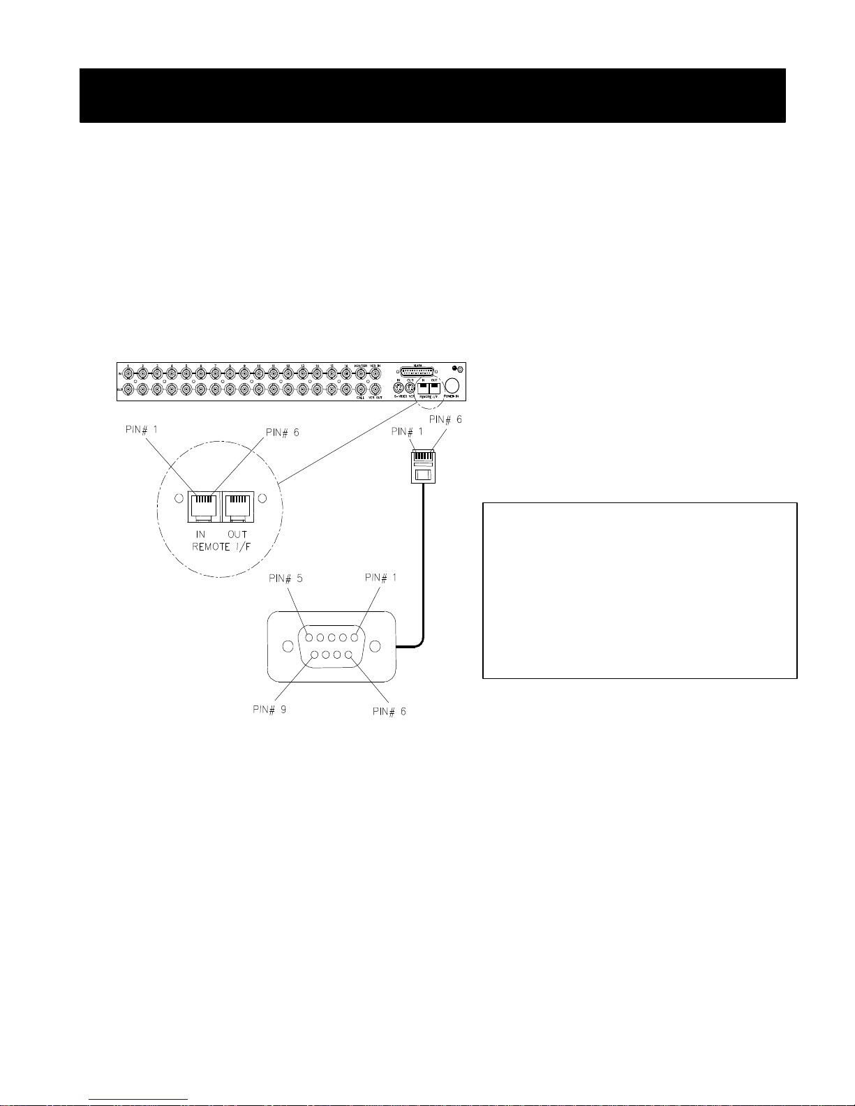
WIRING CHAR
T
Remote I/F
The MP1600/BMP1600’s remote interface allows the remote control of MP1600/BMP1600
with a standard 6
conductor RJ45 cable. With
standard RS232 protocol, the MP1600/BMP1600 can be interfaced
its use of the industry
to any system that supports an RS232 interface, although optional software is required.
Interfacing with PC compatible RS232 ports.
RS232 Interface Setup
Baud rate: 1200 bps
Parity: None
No of Bits: 8
No of Stop bits: 1
-conductor cable that is terminated with a 6-
Remote Interface Diagram
MP900/1600 PC Comp.
RJ-11 Conn. DB-9 Conn. (Female)
1 to 3 N/C
4 (Rx) 3
5 (Tx) 2
6 (GND) 5
N/C 1,4,6,7,8,9
32
Page 34

Remote Interface
MP/BMP1600 Series Remote Interface Command Set
Command Set
Main Secondary Functions
Code Code
a 0 1 Set Main Monitor output to CAM1
b 0 2 Set Main Monitor output to CAM2
c 0 3 Set Main Monitor output to CAM3
d 0 4 Set Main Monitor output to CAM4
e 0 5 Set Main Monitor output to CAM5
f 0 6 Set Main Monitor output to CAM6
g 0 7 Set Main Monitor output to CAM7
h 0 8 Set Main Monitor output to CAM8
i 0 9 Set Main Monitor output to CAM9
j 1 0 Set Main Monitor output to CAM10
k 1 1 Set Main Monitor output to CAM11
l 1 2 Set Main Monitor output to CAM12
m 1 3 Set Main Monitor output to CAM13
n 1 4 Set Main Monitor output to CAM14
o 1 5 Set Main Monitor output to CAM15
p 1 6 Set Main Monitor output to CAM16
/ -Set to Split Screen Mode (Cursor -
Down in Menu Mode)
* ? -Set/Reset Freeze Mode (Cursor Up in Menu Mode)
- -Toggle Live/VCR Modes (Select in
Menu Mode)
+ -Enter/Exit Menu Setup Mode
V a -Set to Live Mode
V b -Set to VCR Mode
v d -Split Screen Mode
v e -Sequence Mode
Main Secondary Functions
Code Code
A . 0 1 Set Call Monitor output to CAM1
B . 0 2 Set Call Monitor output to CAM2
C . 0 3 Set Call Monitor output to CAM3
D . 0 4 Set Call Monitor output to CAM4
E . 0 5 Set Call Monitor output to CAM5
F . 0 6 Set Call Monitor output to CAM6
G . 0 7 Set Call Monitor output to CAM7
H . 0 8 Set Call Monitor output to CAM8
I . 0 9 Set Call Monitor output to CAM9
J . 1 0 Set Call Monitor output to CAM10
K . 1 1 Set Call Monitor output to CAM11
L . 1 2 Set Call Monitor output to CAM12
M . 1 3 Set Call Monitor output to CAM13
N . 1 4 Set Call Monitor output to CAM14
O . 1 5 Set Call Monitor output to CAM15
P . 1 6 Set Call Monitor output to CAM16
33
Page 35

Specifications
Video Inputs
Video Standards NTSC or PAL (depending on model)
Signals
Video Inputs Composite, 1.0V P-P, 75 ohms terminated (16-channels)
VCR Input Composite, 1.0V P-P, 75 ohms terminated
Components, S-Video Standards, 75 ohms terminated
Video Outputs
Video Standards NTSC or PAL (depending on model)
Signals
Loop-back Active, Composite, approx. 95% of input signal
Call Monitor Active, Composite, approx. 95% of input signal
(not a roll-free switching output)
Main Monitor Composite, 1.0V P-P
VCR Output Composite, 1.0V P-P
Components, S-Video Standards (Y-C)
Video Processing
Video Formats
Video Decoding NTSC CCIR601 (858x525 native res.)
& Encoding PAL CCIR601 (864x625 native res.)
Video Processing Fully Digital
Main Monitor 8 channel parallel processing
VCR Output 4 channel semi-parallel processing
Onscreen Display
Camera Identification User selectable, 12-characters per camera
Date/Time 5 date formats, 3 time formats
Switcher Dwell Time Individually controlled (0-59 sec per camera)
Roll-free switching
Alarm Processing
Inputs NO/NC Auto-detection (at power-on)
Outputs Normally Open and Normally Closed
1.0A Max @24V Resistive
or 0.25A Max @120/240VAC Resistive
Remote Interface RS232 Standard, RJ45
Proprietary pinout
Power
System 6A @5V Max
AC Adapter 90-264 VAC, 50-60Hz, 1.7A Max
Dimension 17”(w) x 13”(d) x 1.75”(h)
*Specifications are subject to change without notice.
34
 Loading...