

Page 1

FAA Approved Installation Manual for the Report No 908
EDM-900 and EDM-930 Page 1 of 55 Rev I
Primary Engine Data Management System Date 1-18-2013
TABLE OF CONTENTS
1. Revisions ______________________________________________________________________________________ 3
2. Instrument Marking______________________________________________________________________________ 4
3. Primary TSO Label ______________________________________________________________________________ 4
4. Operation and Abbreviations ______________________________________________________________________ 5
5. Dimming ______________________________________________________________________________________ 6
6. Locating and Installing the Indicator and Remote Alarm Display (RAD and Alert Light) ________________________ 9
6. EDM-900/930 Key information installation __________________________________________________________ 11
7. Routing the Wiring Harnesses_____________________________________________________________________ 12
8. Power Connection ______________________________________________________________________________ 12
9. Wiring Markings _______________________________________________________________________________ 13
10. Exhaust Gas Temperature Probe (EGT) Installation ___________________________________________________ 13
11. RADIAL Engine EGT_____________________________________________________________________________ 14
12. Turbine Inlet Temperature (TIT) Probe Installation (optional) ___________________________________________ 14
13. TIT for second Turbine Inlet Temperature ___________________________________________________________ 14
14. Using the Factory original TIT Probe_______________________________________________________________ 14
15. Cylinder Head Temperature (CHT) Probe Installation__________________________________________________ 15
16. Radial Engine CHT (spark plug gasket) _____________________________________________________________ 15
17. Outside Air Temperature (OAT) Probe Installation ____________________________________________________ 15
18. Induction Air (IAT), Compressor Discharge Temperature Probe Install (optional) ____________________________ 15
19. Carburetor Probe Installation (optional) ____________________________________________________________ 15
20. Oil Temperature Probe Installation ________________________________________________________________ 15
21. Oil Pressure Sensor Installation ___________________________________________________________________ 16
22. Fuel Pressure Sensor Installation __________________________________________________________________ 17
23. Adding a non-primary gauge to the system ___________________________________________________________ 17
24. Fuel Pressure Sensor Installation __________________________________________________________________ 17
25. Ammeter Shunt Installation _______________________________________________________________________ 18
26. Load Meter Configuration________________________________________________________________________ 19
27. Fuel Level Sender Wiring Types ___________________________________________________________________ 20
28. Capacitive Sender Frequency Output Type Sender System _______________________________________________ 20
29. Resistive Output Type Sender System (Float type, most common) _________________________________________ 20
30. Voltage Output Type Sender System ________________________________________________________________ 22
31. Fuel Tank Calibration Setting Fuel Calibration Points _________________________________________________ 22
32. After you have collected your data _________________________________________________________________ 24
33. Fuel Flow Totalizer, Refuel Question _______________________________________________________________ 26
34. GPS Interface _________________________________________________________________________________ 27
35. Manifold Pressure (MAP) Sensor __________________________________________________________________ 27
36. RPM Sensor installation _________________________________________________________________________ 28
37. EDM-900/930 Specifications and Limitations_________________________________________________________ 29
38. EMI Radio Test and functional check:_______________________________________________________________ 30
39. Component Parts_______________________________________________________________________________ 31
40. Weight and Balance Data ________________________________________________________________________ 32
41. Pilot Programming _____________________________________________________________________________ 33
42. Programming the HP Constant ____________________________________________________________________ 33
43. Selecting Fuel Pressure Type (EDM-900 only)________________________________________________________ 34
44. Customizing Non-Primary Data (EDM900 only) ______________________________________________________ 34
45. K Factor______________________________________________________________________________________ 34
46. Adjusting the K Factor___________________________________________________________________________ 37
Page 2

FAA Approved Installation Manual for the Report No 908
EDM-900 and EDM-930 Page 2 of 55 Rev I
Primary Engine Data Management System Date 1-18-2013
47. Programming Accumulate Trip Total _______________________________________________________________ 37
48. Trouble Shooting _______________________________________________________________________________ 38
49. Connector Pin Assignments on EDM, J1 through J5 _______________________________________________ 40
50. Connector Pin Assignments on EDM, J1 through J5 ___________________________________________________ 41
51. J3 RPM, MP, Oil-P_____________________________________________________________________________ 44
52. Appendix A Fuel Flow install Report 503 ___________________________________________________________ 48
53. Appendix B ICA _______________________________________________________________________________ 48
54. Appendix C Connector Pin Assignments on EDM, J1-J2 Only with ARINC 429 _____________________________ 49
The Owner of the EDM-900/930 must keep this manual
J.P. INSTRUMENTS
PO BOX 7033
HUNTINGTON BEACH CA
Last printed 1/24/2013 4:14:00 PM
Page 3
FAA Approved Installation Manual for the Report No 908
EDM-900 and EDM-930 Page 3 of 55 Rev I
Primary Engine Data Management System Date 1-18-2013
1. Revisions
REV Description Date Approval
G
Added new pictures of 900 and 930, page 6. Abbreviations page 4. Revised how the
JPI data base functions, page 3. Added revision box. Page 2. Added fuel level
calibration, page 22. Renumbered all pages.
9-28-2011 JFP
H
Revised to include new trouble shooting section for ICA and renumber pages. Updated
pressure sensors to i2s
12-02-2011 JFP
I
Revised TSO Label to show lighting change and added ARINC 429 wire chart 1-18-2013 JFP
Read This First
The following notes apply to a new installation. Read this section before proceeding.
The JPI warranty found in the back of the pilots guide clearly states that JPI will replace defective parts under
warranty, but does NOT cover labor to remove or install any parts.
The most common cause of probe problems is poor terminal crimps. Crimp ring terminals with AMP tool or
equivalent. Fold back the wire double before crimping terminals.
Do not use aluminum fittings or Teflon tape or pipe sealant with the FXT-201 or FXT-231 fuel flow transducer.
Write down the K-factor engraved on the side of the fuel flow transducer here _______. Once the transducer is
installed and covered with the fire sleeve, you will not be able to access this K factor.
Determine the locations of all holes before drilling to ensure that nothing interferes with the probe, clamp, clamp
screw or wire.
Provide service loops at the instrument so that it can be moved for maintenance or troubleshooting.
Thermocouple wire length is not critical. Trim to required length, allowing for service loops at the engine so that
probes can be swapped with probes on adjacent cylinders for troubleshooting purposes.
Dress all wires away from high temperature components such as exhaust stacks.
Never splice thermocouple wire using copper wire. Use only K-type thermocouple wire. Solder using zinc
chloride flux such as Nokorode brand – rosin flux alone will not work.
Observe correct polarity on all probe wires. Connect like colors together (red to red, yellow to yellow).
The instrument must be grounded at the engine, not at the avionics ground.
Record the installation of the EDM-900 or EDM-930 on a FAA form 337. Make an entry in the aircraft logbook.
Note: Removal of probes, sensors and the instrument is the reverse of the installation procedure.
Page 4
FAA Approved Installation Manual for the Report No 908
EDM-900 and EDM-930 Page 4 of 55 Rev I
Primary Engine Data Management System Date 1-18-2013
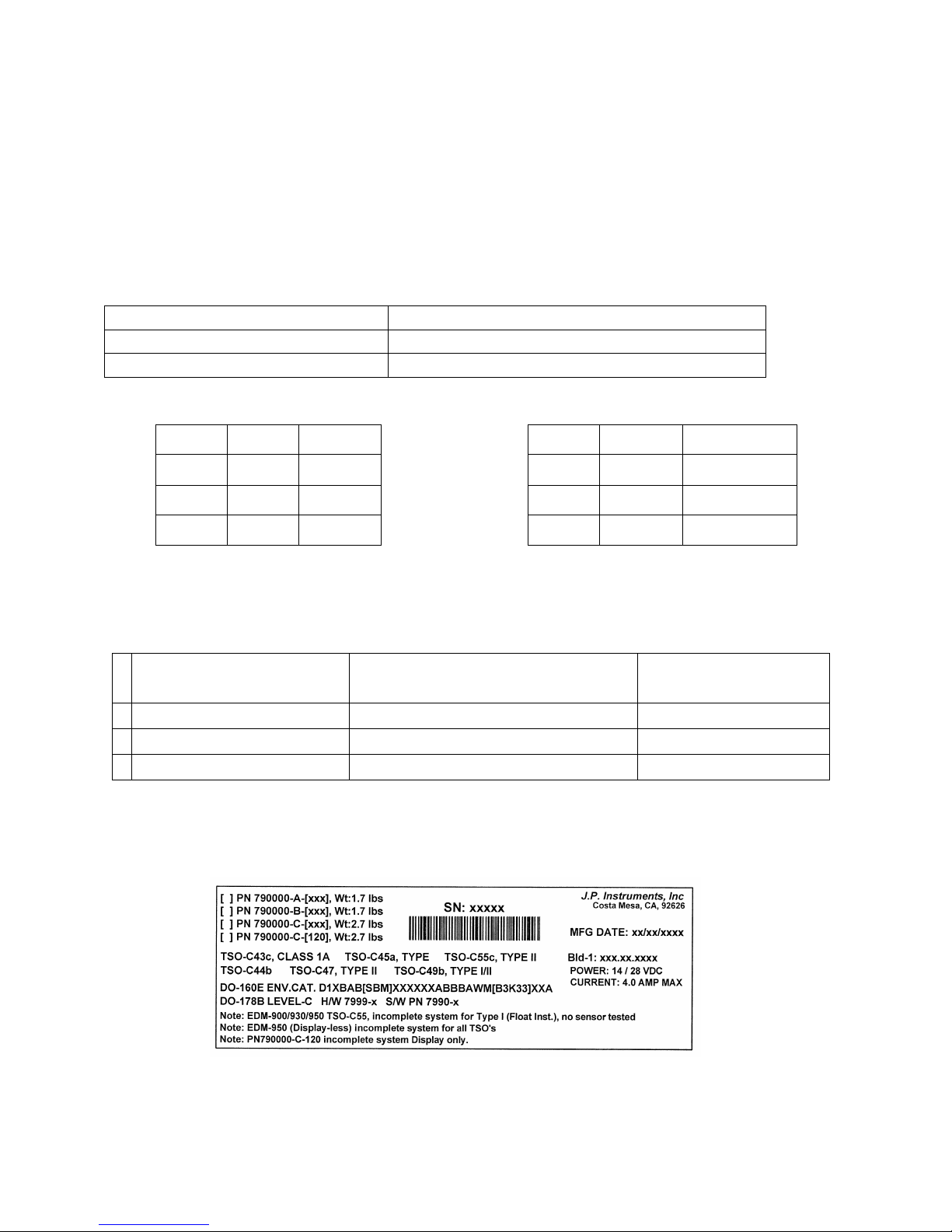
2. Instrument Marking
The TSO label on the instrument is marked as to the instrument configuration.
The part number of the instrument is as follows:
Model designation system by part number for EDM-900/930
Model Number / Part Number Description
EDM-900 PN 790000-A- [XXX] TFT (liquid crystal) Type Display
EDM-930 PN 790000-C- [XXX] TFT (liquid crystal) Type Display
INSTRUMENTS THAT CAN BE PRIMARY IF IN POH NON-PRIMARY INSTRUMENTS
CHT
4-9
FUEL
FLOW
RAD
Alert Light
EGT
4-9
Time to
empty
Fuel Remaining
Fule USED
OIL
TEMP
FUEL
PRESS
TIT OAT
CARB
Required
to WP
Shock Cooling
OIL
PRESS
RPM CDT Volts
Amps
Reserve atWPDifferential EGT
Normalize
MAP FUEL
Quantity
IAT MPG Percent of HP
Example PN 790000-(X)-(XXX) (X) denotes EDM-900 or EDM-930, (XXX) denotes Part Number for a specific
aircraft with or without and engine STC. Each PN is specific to a Make and Model Aircraft with or without
STC. In which the information is gathered from the Aircraft POH or STC Data sheet.
Aircraft type
w/engine STC No. if
applicable
JPI assigned Data Base Part No. per
Limits found in the POH or engine STC
for a specific aircraft
Part No. Displayed on 930
RAD at Start-up or 900
message area
Cessna 182-P 534 790000-X-534
Cessna 182-P, STC12345NW 875 790000-X-875
3. Primary TSO Label
Page 5

FAA Approved Installation Manual for the Report No 908
EDM-900 and EDM-930 Page 5 of 55 Rev I
Primary Engine Data Management System Date 1-18-2013
4. Operation and Abbreviations
The EDM-900/930 is a combined electronic indicating system which simultaneously displays to the pilot powerplant
and aircraft systems operating parameters. It includes the following indicating systems; replacing all previous
primary digital and/or analog instruments: Message Area Abbreviation in parenthesis. (X)* denotes cylinder No.
Gauge Function
Message Area
Alarm Abbreviation
Primary Primary
Engine rotational speed RPM xxxx
Engine Manifold Pressure MAP xx.x in hg
Engine Cylinder Head Temp CHT2 xxxoF
Engine
Oil Temperature
O-T xxxoF
Engine Oil Pressure O-P xxxoF
Fuel Pressure F-P xx PSI
Fuel Flow to engine F-F xx.x GPH
Comp. Discharge Temp. CDT xxxoF
Turbine inlet Temp. Left side TIT-L xxxxoF
Turbine Inlet Temp. Right side TIT-R xxxxoF
Single Turbine Inlet Temp. TIT xxxxoF
Non-Primary Non-Primary
Exhaust Gas Temp. EGT2 xxxxoF
Shock Cooling of CHT CLD xxo/MIN
Differential Temp. of EGT DIF xxoF
Bus Voltage Volts xx.x
Amperage Load AMPS xx
Outside Air Temp. OAT xxoF
Estimated Time to Empty Est. T to E xx:xx H:M
Fuel used to date USED xx.x GAL
Estimated Remaining fuel Est. REM xx GAL
Estimated Fuel required to Waypoint Est. WP REQ xx GAL
Estimated Fuel Remaining at Waypoint Est. WP RES xx GAL
Nautical Miles per Gallon ECON xx.x MPG
Brightness, Dim control DIM/BRT
Page 6

FAA Approved Installation Manual for the Report No 908
EDM-900 and EDM-930 Page 6 of 55 Rev I
Primary Engine Data Management System Date 1-18-2013
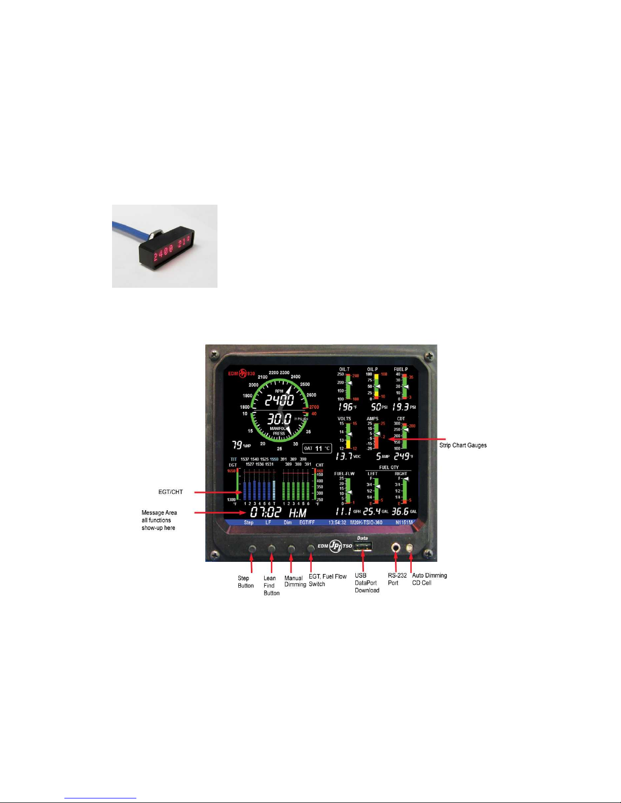
Remote Alarm Light EDM 900
The remote alarm light is a Red or Yellow light depending on the alarm condition. The EDM-900 incorporates a
single light that alerts the pilot that a problem existing within the engine. This light is place in with the primary flight
instruments and required only if the display is more than 8 inches from the center of the instrument “T” to a max of
21 inches. It is a single light that changes color with condition and the label associated with the light must be lit by
a post light or such that you can see the word “ENGINE”.
Remote Alarm Display (RAD) Operation EDM-930
The RAD is a 0.2” high, 8 character independent display found on the EDM-930 only. The RAD will still function if
the main display is inoperable. An alarm—such as the CHT is 480° on cylinder number 2—is displayed as
480CHT2. The label CHT2 will flash whenever an over-temperature exists and will extinguish when the temperature
falls below the limit temperature. Other alarms would be displayed as, for example: 2780 RPM.
The RAD is located directly in front of the pilot and displays digital caution and limit excedances when any of the
parameters have reached its preset trigger point. Whenever limit alarms are not triggered, the RAD continuously
displays MAP and RPM.
On initial startup or whenever power is turned on, the words EDM-930 PRIMARY” are displayed, followed by the
make and model of the aircraft with STC information for which the primary limits were set
Alarm hierarchy for the EDM-900/930
When a measurement limit is reached, the pilot should momentarily depress the STEP button on the EDM-900/930
instrument to extinguish the particular flashing alarm acronyms. If another function has also reached its limit, that
label will then begin to flash. The pilot should continue to monitor the affected parameters as he would if a
conventional analog display had reached a limit. The bar graph functions of CHT, EGT, and TIT remain displayed
for easy reference should one of these limits be reached. Alarm hierarchy is shown in the table below.
1. OILP_LO.
2. FP_LO.
3. OILT_HI.
4. CHT.
5. TIT.
6. FLVL.
7. REM.
8. FP_HI.
9. MAP.
10. DIF.
11. CLD.
12. RPM.
13. OILT_LO.
14. VOLTS.
15. OILP_HI.
16. AMPS.
17. CDT.
18. RES.
19. EGT.
20. Fuel Flow.
5. Dimming
Automatic dimming is provided to dim both the panel display and the remote alarm display. Dimming can also be
accomplished manually to change the Automatic setting. Tapping the far right button below the display decreases
brightness. Continuously holding this button increases brightness. The display starts up in the max brightness mode.
Page 7
FAA Approved Installation Manual for the Report No 908
EDM-900 and EDM-930 Page 7 of 55 Rev I
Primary Engine Data Management System Date 1-18-2013
EDM-930 Display
RAD
Page 8
FAA Approved Installation Manual for the Report No 908
EDM-900 and EDM-930 Page 8 of 55 Rev I
Primary Engine Data Management System Date 1-18-2013
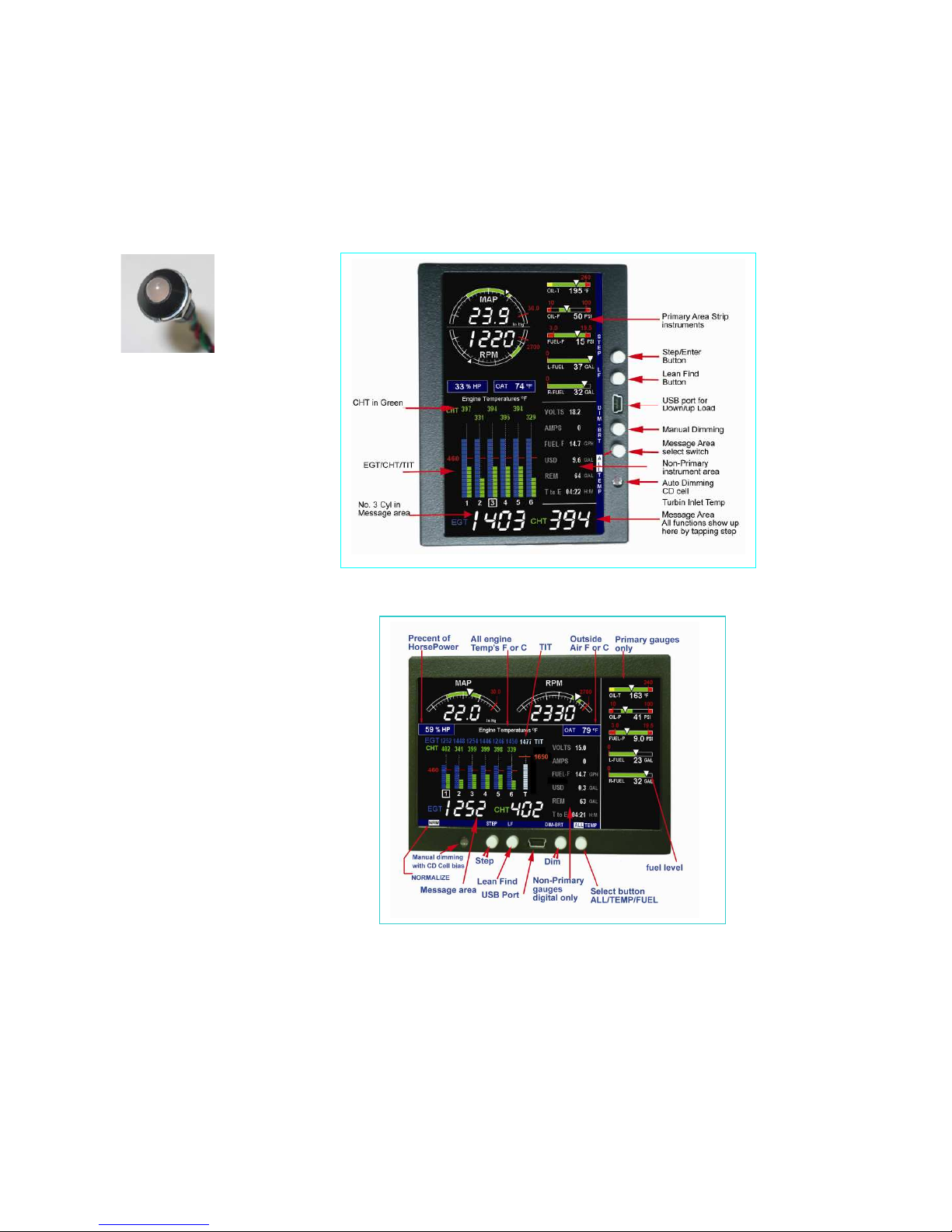
EDM-900 TFT Flat panel display
Portrait Mode
EDM-900 TFT Flat
panel display
Landscape Mode
EDM-900 system mounts in a 3.125 inch diameter instrument panel hole in either a portrait or landscape position
depending on panel hole location. By holding the Step button ( first on left) for approx. 10 seconds and arrow will
appear on the display showing which way the rotation will use as up. Use the LF (Second from left) button to index
the rotation arrow. When the proper position is achieved, tap the step button Tap STEP to save the new rotation.
At this point properly the rotation will be saved and the unit will reboot to the new rotation. The rotation will not
occur if the engine is running.
Remote Alert Light
With the placard
“Engine”
Page 9
FAA Approved Installation Manual for the Report No 908
EDM-900 and EDM-930 Page 9 of 55 Rev I
Primary Engine Data Management System Date 1-18-2013
6. Locating and Installing the Indicator and Remote Alarm Display (RAD and Alert Light)
Single Engine Aircraft EDM-900/930
A) The EDM-900/930 display should be located as close as possible to the pilot with an unobstructed view
and for easy access to the buttons on the instrument. The least desirable view angle is landscape looking
up. To improve the view angle call the factory. A remote display is also provided for alarm indications and
should be directly in front of the pilot.
B) The RAD PN-790749 mounts in a 5/8 inch hole in the panel directly in front of the pilot for the EDM-930
and an alert light for the EDM-900 is mounted in a 3/8 dia hole.
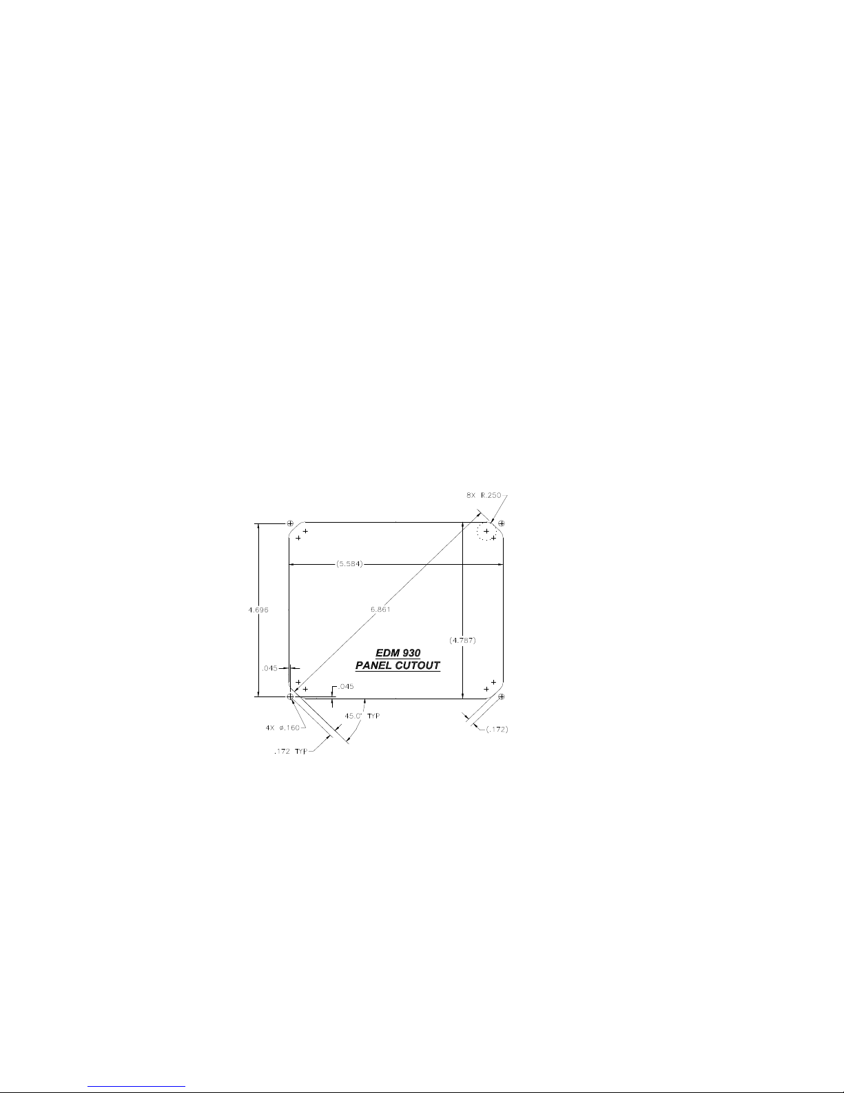
The diagram below should be used as a guide for cutting and drilling the mounting and buttonholes in the
instrument panel. The dimensions shown are for the finished cutout. Allow extra clearance for any panel finish such
as powder coat. The EDM mounts from behind the panel through this cutout. Fabricate the appropriate cut-out
using the fig below as a guide. If the panel has too many holes for a clean installation, it is recommended that a
0.10” aluminum overlay panel be constructed and installed over the original instrument panel and the EDM be
installed into this overlay panel. The Remote Alarm Display PN-790749 mounts in a 5/8 inch hole in the panel
immediately above the Attitude Gyro / D.G. / HSI +/- 0.5 inches from their centerline directly in front of the pilot.
4.1 Figure 1:
Page 10
FAA Approved Installation Manual for the Report No 908
EDM-900 and EDM-930 Page 10 of 55 Rev I
Primary Engine Data Management System Date 1-18-2013
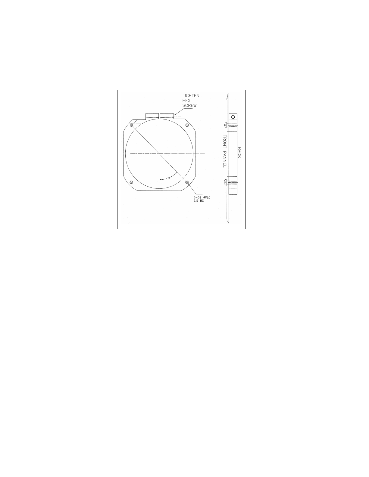
Mounting bracket for the EDM-900
EDM-900 Model: Mounts in a standard 3.1/8” instrument hole. First, place the mounting bracket on the
instrument and tighten the clamp hex screw until you can just remove the instrument from the bracket. The
Mounting bracket is then placed behind the instrument panel hole and screwed (6-32 x ½” screws) in place using
the existing holes. Three screws should be used leaving one hole vacant on either side of the hex screw. Locate
the hex screw in a location that you can easily get to from the rear of the panel. The body of the instrument is 3.0
inches in diameter and 2.0 inches deep less connectors.
Page 11
FAA Approved Installation Manual for the Report No 908
EDM-900 and EDM-930 Page 11 of 55 Rev I
Primary Engine Data Management System Date 1-18-2013
5. EDM Display Installation
Choose the Proper Installation Location
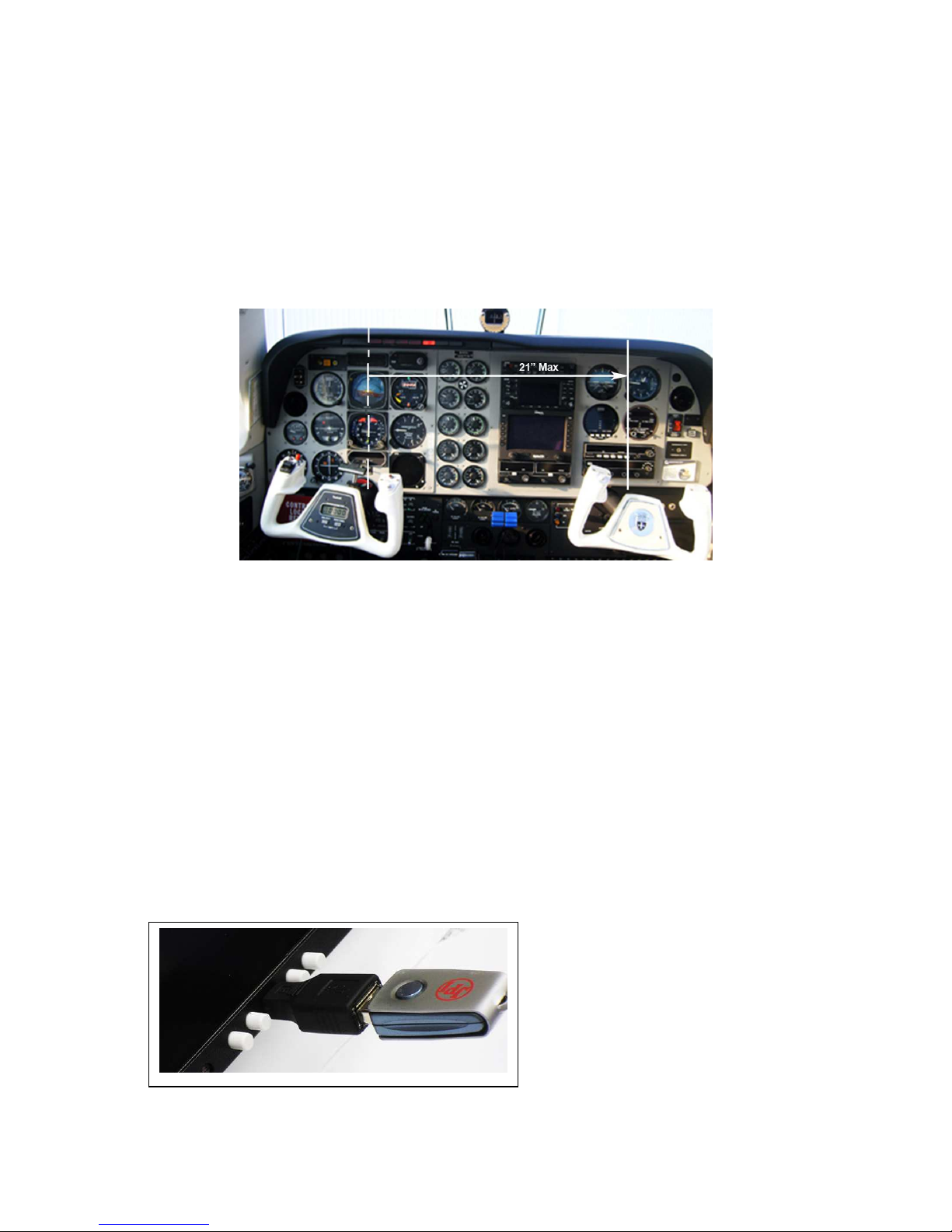
The display is best located within the natural scan and easy reach of the pilot. The recommended mounting location
is defined as the distance from the vertical centerline of the Primary Flight Instruments to the outer edge of the
further most gauge displayed on the EDM.
HORIZONTAL ORIENTATION:
The EDM display may be mounted from the vertical centerline of the Primary Flight Instrument “T” to a maximum of
21” to the further most gauge of the EDM display and to the left of the centerline as much as needed.
VERTICAL ORIENTATION:
The EDM display is to be mounted within +/- 10” from the horizontal centerline of the Primary Flight
Instrument “T”. The installer should insure that the EDM display is not obstructed by either
the glare shield or the control wheel.
The installing A&P and IA must insure that the installation location complies with the viewing angle requirements
listed above.
6. EDM-900/930 Key information installation
Aircraft specific configuration information is loaded differently on both the EDM-900 and the EDM-930. The
configuration data is the same for both instruments. The data for the EDM-900/930 is loaded via the mini USB port
on the EDM-900 and a standard USB port for the EDM-930.
Page 12

FAA Approved Installation Manual for the Report No 908
EDM-900 and EDM-930 Page 12 of 55 Rev I
Primary Engine Data Management System Date 1-18-2013
Be sure to verify that this matches your aircraft.
Note: If your EDM should ever have to be replaced with a different unit, the factory will reprogram it to match your
configuration. You should always retain your fuel quantity calibration records, as these may need to be manually reentered in a different or serviced unit.
7. Routing the Wiring Harnesses
Five connectors are protruding from the rear of the instrument. Connect the five wiring harnesses to the rear of the
instrument and run the cables through the firewall into the engine compartment. Allow sufficient service loop to
facilitate removal of the connectors for servicing. These wiring harnesses are labeled as follows:
Conn Harness PN
P1 790200 Power, Engine ground, MFD input, MFD output the following are optional and need
to be added : Oil temperature, Induction temperature, Carburetor temperature,
Outside air temperature, Turbine inlet temperature, Turbine inlet temperature 2,
P2 700700
700702
CHT, EGT 6 cylinder
CHT, EGT 4 cylinder
P3 790420 RPM, MAP, Oil pressure
P4 700708 Serial data to GPS, Serial data from GPS, Fuel flow transducer
P5 790749 Fuel Pressure, Fuel Level (Resistive and Capacitive ), Amps
RAD 790749 Category 5 jack and cable for RAD (Remote Alarm Display)
Route the wires from the connectors through the firewall using rubber grommets and flame retarding silicone. Use
an existing hole if possible. All wires must be routed away from high temperature areas (exhaust stacks,
turbochargers, etc.). Secure probe and sensor leads to a convenient location on the engine approximately 8 to 12
inches from the probe or sensor, being sure there is sufficient slack to absorb engine torque. It is essential in
routing the probe wire that this wire not be allowed to touch metal parts of the air-frame or engine since abrasion
will destroy this high temperature wire. Secure wires along the route to the indicator. Secure wire using original
clamps, tape or tie wrap if possible.
Note: The probe wires must not be tied in with ignition, alternator or engine cabin heater ignition wires or
transceiver coax cables because of potential induced interference with readings.
The temperature probe wiring harness is made of Chromel-Alumel alloy wires that must not be substituted or
extended with copper wire. Temperature probe leads must be spliced with the same type of wire (typically
Chromel-Alumel for JPI temp probes) using copper butt splices. The other signal and power wires are made from
normal copper and must meet MIL-W-32759/16 or equivalent.
CAUTION: Be sure the installation does not result in interference with any aircraft control movements.
When the installation is complete all wires should be secured using ties and carefully checked for interference,
rubbing or chafing with flight controls and associated cables or any other moving parts.
8. Power Connection
The EDM automatically adapts to either a 14 or 28-volt electrical system. Master Bus power wire to the EDM
should be 20ga copper connected directly to the master solenoid located at the battery to avoid a line drop when
cranking. A 5 amp circuit breaker is required. Connect the EDM ground wire to the engine block. The
instrument is designed to reset at less than 10vdc bus power, therefore the instrument may reset on engine start
(typical for 14vdc systems). For lighting, no connection to the aircraft dimmer system is required because the
instrument dims automatically with reductions in ambient light. Required power for 900 or 930 is 1.0 amp at 14vdc
Probe Wiring
When cutting the pair of leads to the proper length to connect to the probes, leave enough slack in the wiring so
that probe may be interchanged to an adjacent cylinder if necessary for trouble-shooting and servicing.
Thermocouple wire length is not critical and should be trimmed to any length as required for a clean installation.
Page 13
FAA Approved Installation Manual for the Report No 908
EDM-900 and EDM-930 Page 13 of 55 Rev I
Primary Engine Data Management System Date 1-18-2013
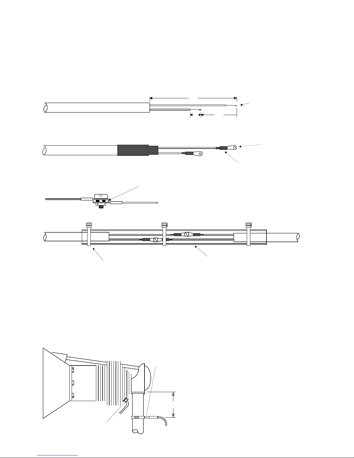
The Temperature probe must be wired with the correct polarity. The temperature probe connects to its temperature
indicator with yellow jacket Teflon Chromel Alumel wire supplied. Strip the wires as shown below—observing colorcoding.
1/4" 1 1/2"
Fold back wire
double before
crimping terminals
2 1/4"
Thermocouple wire harness
red
yellow
Terminate each wire with a crimp-on ring terminal, provided. The ring terminals may be crimped with an AMP part
number 48518 crimp tool is recommended however, a “service-type” tool may also be used. Verify the quality of
each crimp with a sharp tug on the wire. The terminal should be impossible to pull off when crimped correctly.
shrink tubing
ring terminal
Place a ¼ x 4-inch sleeve over each pair of wires in the wiring. Connect the wire ring lug to the probe ring lug using
the supplied number 4 screws and nuts, placing the star washer between the ring lugs, not against the nut.
Important: place star waster between two ring
terminals and tighten nut and bolt as
necessary
to instrument
to probe
Slide the sleeve over the joint and secure with three tie-wraps.
1/4 x 4" sleeve
tie-wrap 3places
The most common installation problems are related to poor quality terminations.
9. Wiring Markings
The EDM-900/930 is supplied with special Teflon insulated Chromel Alumel factory assembled wiring harness
configured for the correct number of cylinders. The wire harness is marked E1= EGT-1, C1= CHT-1, etc.
NOTE: Unlike most other EGT & CHT installations the probe wire length is not critical and should be
trimmed to any length as required for a clean installation. Do not extend the thermocouple wire with
copper wire.
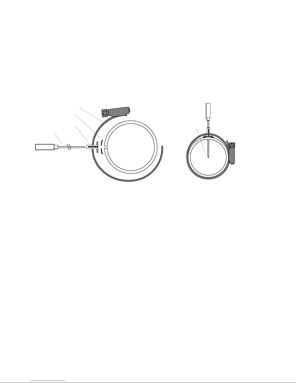
10. Exhaust Gas Temperature Probe (EGT)
Installation
Use the J2 connector harness 700700 or 700702
labeled E1 through E4 or E6. Remove the existing
EGT gauge and Probe. Replace with JPI probe M111 in all exhaust stacks.
The Model M-111 Probe will fit any engines where
the existing holes in the exhaust stack are 1/8" to
1/4" in diameter. If no hole exists, it will require the
drilling of a 1/8" diameter hole and ream to fit. It is
important that each probe be mounted the same
2" to 4"
EGT probe
Drill no. 40
pilot hole,
then no. 30
hole.
CHT probe
exhaust stack
Page 14
FAA Approved Installation Manual for the Report No 908
EDM-900 and EDM-930 Page 14 of 55 Rev I
Primary Engine Data Management System Date 1-18-2013
distance from its exhaust stack flange. A nominal distance of 2 to 4 inches from the exhaust flange is
recommended. If the recommended distance is impractical because of obstructions, slip joints or bends in the
exhaust system then position the probes a uniform distance from the flange as space permits. Do not mount
probes in slip joints. Be certain to locate all holes BEFORE drilling to ensure that nothing interferes with the
probe, clamp, screw or wire. Careful matching of probe position will provide best temperature readings.
Insert the probe in the exhaust or previously drilled hole so that the tip of the probe is in the center of the exhaust
stream. Tighten the stainless steel clamp to a torque of 45 in/Lbs. Cut off the excess strap close to the screw.
Position probe
in approximate
center of
exhaust
Probe
Clamp
Thimble
note orientation of
slot
Seal Washer
11. RADIAL Engine EGT
Radial engine exhaust, require a larger EGT clamp (supplied) to fit the 2.5 inch exhaust pipe. The EGT probe is installed in the
same fashion as a Lycoming or Continental engine and should be placed between the exhaust pipe flange and the accumulator
at a distance of 2 to 3 inches from the engine exhaust flange. Refer to the engine manufactures recommended location. Do not
route the EGT/CHT harness in with the ignition harness. Do not extend the yellow thermocouple leads with copper wire.
12. Turbine Inlet Temperature (TIT) Probe Installation (optional)
Use the J1 connector harness 790200 and insert the yellow wire into the connector pin 16 and the red wire into pin
17. The standard TIT probe PN M111-T with a #48 clamp is placed in the exhaust stack accumulator to a maximum
depth of 1/2 inch and approximately 4 inches from the turbine inlet if possible, on the waste-gate side of the turbine.
13. TIT for second Turbine Inlet Temperature
Use the J1 connector harness 790200 and insert the yellow wire into the connector pin 18 and the red wire into pin
19. The standard JPI TIT probe P/N M-111-T with a special clamp is placed in the exhaust stack accumulator to a
maximum depth of 1/2 inch and approximately four inches from the Turbine inlet if possible, on the waste gate side
of the turbine.
14. Using the Factory original TIT Probe
The factory installed TIT probe (K-calibration) is compatible with the JPI EDM-960 System. Connect the JPI wire
marked TIT. Replacement probes should be purchased per part number from the aircraft manufacturer.
The EDM-960 permits you to remove the factory installed TIT indicator and leave the TIT probe installed. Connect
the JPI wire marked TIT directly to the probe noting color polarity. The TIT probe should now have only the JPI
leads attached to it. No calibration of the EDM-960 is necessary
Page 15
FAA Approved Installation Manual for the Report No 908
EDM-900 and EDM-930 Page 15 of 55 Rev I
Primary Engine Data Management System Date 1-18-2013
15. Cylinder Head Temperature (CHT) Probe Installation
Use the J2 connector harness 700700 or 700702 labeled C1 through C4 or C6. The JPI probe is a bayonet probe
P/N 5050-T that has a captive 3/8-24 boss that is screwed into the head of each cylinder.
For Indicator replacement, replace your existing CHT probe and adapter, a bayonet or screw in type with one
supplied by JPI. Install the probe on the same cylinder from which you removed the original equipment probe. Your
current CHT probe is installed in the hottest cylinder as determined by the airframe manufacturer.
16. Radial Engine CHT (spark plug gasket)
Cylinder head temperatures are measured with a spark plug gasket type probe placed under the front sparkplugs.
Front spark plugs will read 15 to 20 degrees cooler than the rear plugs. The spark plug gasket probe, P/N M-113,
replaces the standard copper spark plug gasket on one spark plug. The probe is usually placed on the plug that
receives the most direct cooling air. After many removals the probe may be annealed for re-use. Heat to 1100oF
and quench in water.
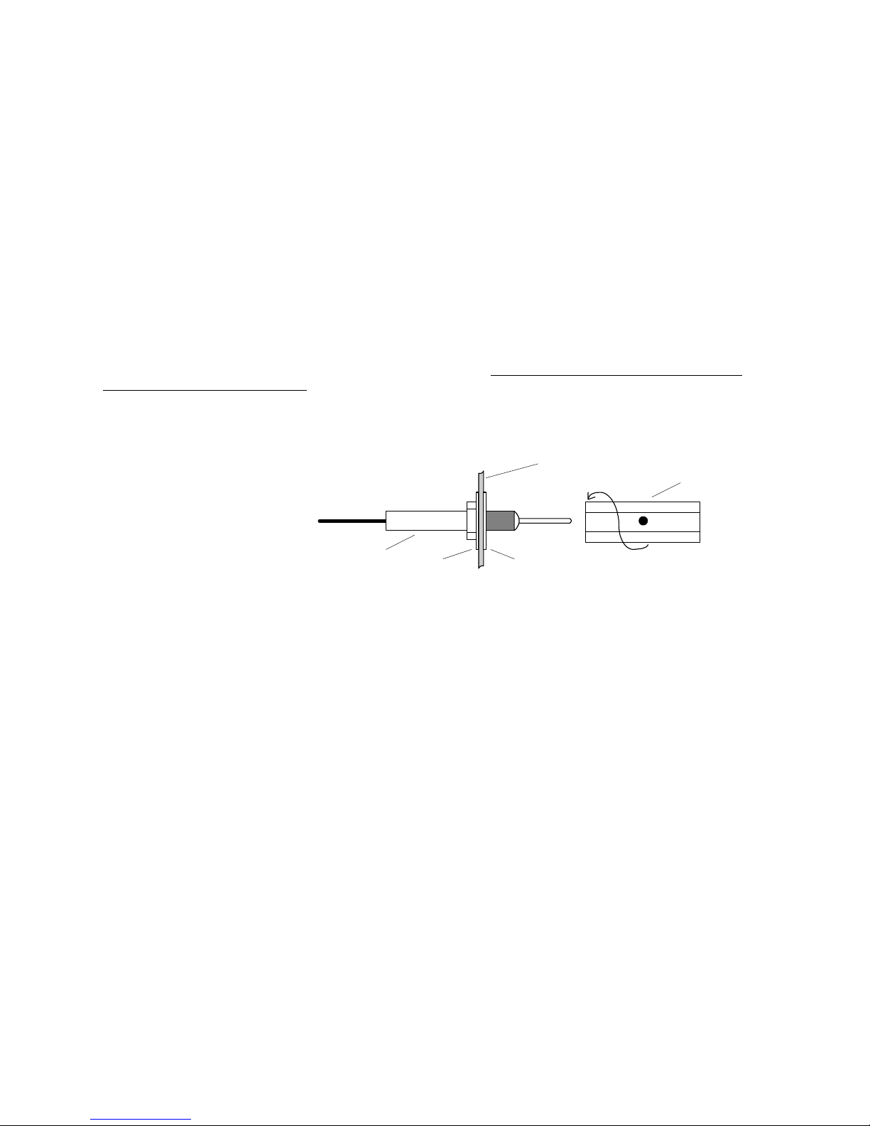
17. Outside Air Temperature (OAT) Probe Installation
Use the J1 connector harness
790200 labeled OAT. All wiring
must be type K thermocouple
wire. Do not splice ordinary
copper wire in any temperature
probe circuits.
Install the OAT probe, PN 400510
in the airframe manufacturer’s
recommended location. If this information is not available, place the OAT probe in clean airflow such as in a cabin
air scoop or below the underside of the wing away from engine heat or exhaust. In this case it is recommended that
the installation be done similar to the antenna installation instructions of AC 43.13-2b Acceptable Methods,
Techniques and Practices.
The outside aluminum shield tube is used to both hold the probe in place and shield it from radiated heat from the
sun. The OAT option is displayed as an independent digital temperature bar graph such as "75.”
18. Induction Air (IAT), Compressor Discharge Temperature Probe Install (optional)
Use the J1 connector harness 790200 and insert the yellow wire into the connector pin 3 and the red wire into pin
4. All wiring must be type K thermocouple wire. The Induction Air Temperature probe, (IAT), is installed just after
the inter-cooler and the Compressor Discharge Temperature (CDT) just before the inter-cooler. The probe is the
same as an EGT probe and installed similarly to an EGT probe. A large clamp is supplied to fit around the air duct
leaving the inter-cooler. Alternately a 1/8 NPT fitting is available. IAT option is displayed as an independent digital
temperature like "125 IAT". On non-turbo engines the IAT in reality is the Carburetor temperature and displayed as
“34 CRB.”
19. Carburetor Probe Installation (optional)
Use the J1 connector harness 790200 and insert the yellow wire into the connector pin 5 and the red wire into pin
6. All wiring must be type K thermocouple wire. Do not splice ordinary copper wire in any temperature probe
circuits. Locate the access hole (1/4-24 thread) in the carburetor near the butterfly valve. Remove the screw plug
now in that hole and screw the CRB probe into the carburetor throat. No drilling or machining of the carburetor is
necessary.
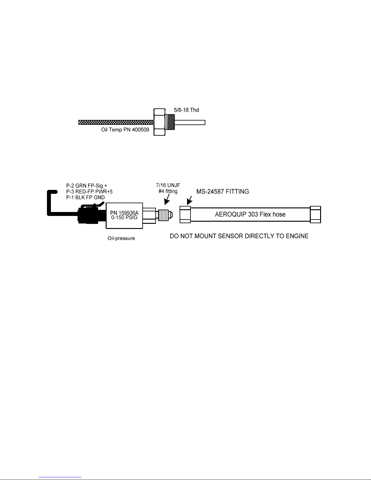
20. Oil Temperature Probe Installation
The sensor port is a standard 5/8-18 thread for both the Continental and Lycoming engines. Probe PN 400509 is a
complete assembly using type K thermocouple wire (red/yellow). Connect the wire marked oil temperature
washer
aircraft sheetmetal
washer
probe
shieldtube
used to secure
probe
Page 16
FAA Approved Installation Manual for the Report No 908
EDM-900 and EDM-930 Page 16 of 55 Rev I
Primary Engine Data Management System Date 1-18-2013
observing polarity to pin 1 and 2 on 790200. Wire length has no effect on the readings. Oil temperature will be
displayed as an independent temperature digital and bar-graph. Check with engine manufactures proper location
for oil temperature. Check for oil leaks before first flight.
21. Oil Pressure Sensor Installation
Use the J3 connector harness 790420 labeled OIL-P for a VDO pressure sensor PN 306018 (0-150 psi) (shown in
diagram below). Use pin 4 for a Sensym pressure sensor (not shown) or three wire i2s sensor (0-5vdc)
Oil pressure sensor mount using an aluminum clamp MS21919. Mount to firewall.
Mount the pressure sensor to the pressure line using a flexible hose and fittings (not supplied) as depicted in the
drawing below. Use aluminum clamp to mount the pressure sensor to firewall. Do not mount the sensor directly to
the engine. Connect the other end of the hose to the engine manufacturer’s recommended location for engine oil
pressure.
Page 17

FAA Approved Installation Manual for the Report No 908
EDM-900 and EDM-930 Page 17 of 55 Rev I
Primary Engine Data Management System Date 1-18-2013
22. Fuel Pressure Sensor Installation
Use the J5 connector harness 790719-X labeled FUELP.
Mount the pressure sensor to the pressure line using a flexible hose and fittings (not supplied) as depicted in the
drawing below. Use Aluminum Clamps MS21919WDG25, or WDG14 to mount the pressure sensor to engine
mount structure or firewall. Do not mount the sensor’s directly to the engine. Connect the other end of the hose to
the existing pressure line. Later, you will connect the pressure sensor to the four pressure sensor wires through the
supplied 4-pin connector. Part No. 790775() required for Carburetor engines OR Transducer PN 3060-17 for
injected engines. PN 3060-17 is a resistive and requires two wires with no polarity.
For Sensym sensor (shown below), crimp the four pins of the female Molex connector to the harness,
matching the wire colors. Secure to firewall with Aluminum Clamp MS21919 WDG14. For injected
engines use clamp MS21919WDG 25.
23. Adding a non-primary gauge to the system
Requirements: new generation EDM-930 with software from June 2010 or later
Steps:
Download EDM Config from JPITech.com (On Software Downloads page)
After “installing” EDMConfig on USB stick, insert into EDM-930 and hold STEP/LF during power up
Step through EDMConfig messages to “EDIT GAUGES” message
o STEP through gauge position to select the EDM-930 gauge to be replaced with FP
o Select “MODIFY” function
On gauge edit screen STEP until the gauge name is selected, then tap MODIFY
§ Tap YES to confirm change of channel
§ Tap NEXT until FUEL-PSI is displayed, tap SAVE
§ Tap YES to confirm change, tap NEXT
o Use NEXT and PLUS/MINUS keys to adjust color bands and limits for FUEL-PSI gauge
o Tap SAVE to save changes to the gauge, YES to confirm
o Tap DONE to exit gauge editing mode.
Tap NEXT repeatedly until EDIT CHANNELS is displayed
Tap yes to edit channels
o Tap STEP several times to select FUEL PRES input channel
o Tap ENABLE key to enable the input
o Tap SAVE, then YES to save change to channels
Tap STEP key repeatedly until prompted to exit configuration, EDM will restart with FP enabled
24. Fuel Pressure Sensor Installation
Use the J5 connector harness 790723.
Mount the pressure sensor to the pressure line using a flexible hose and fittings (not supplied) as depicted in the
drawing below. Use Aluminum Clamps MS21919WDG25, or WDG14 to mount the pressure sensor to engine
mount structure or firewall. Do not mount the sensor’s directly to the engine. Connect the other end of the hose to
the existing pressure line. Later, you will connect the pressure sensor to the three pressure sensor wires through
the supplied 3-pin connector. Part No. 159935A is for non-turbo engines and PN 159938 had a second port used
to measure the upper deck pressure on turbo charged engines.
Page 18
FAA Approved Installation Manual for the Report No 908
EDM-900 and EDM-930 Page 18 of 55 Rev I
Primary Engine Data Management System Date 1-18-2013
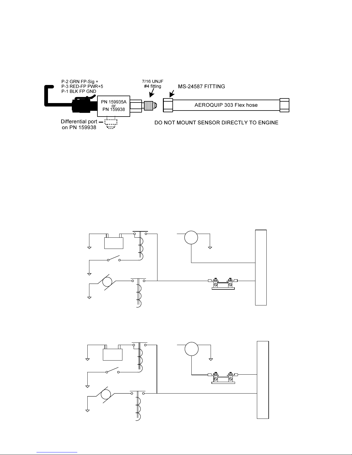
25. Ammeter Shunt Installation
Use the J5 connector harness 790719-X labeled AMP+ and AMP-. Connect the harness leads using ring terminals
to the smaller terminal screws on the side of the shunt.
25.1 Charge/Discharge configuration
The shunt can be installed between the master contactor and the main bus in which case it will be in the ammeter
configuration showing battery charge and discharge. Be sure that the positive side of the shunt is connected to the
main bus in the ammeter configuration. The alarm will be triggered by a discharge condition.
- BATT+
Master switch
Starter Starter solenoid
Master switch
contactor
Bus
F G
B
external shunt
Ammeter Configuration
Alternator
+
- BATT +
Master switch
Starter Starter solenoid
Master switch
contactor
Bus
F G
B
external shunt
Load Meter Configuration
Alternator
+
Page 19
FAA Approved Installation Manual for the Report No 908
EDM-900 and EDM-930 Page 19 of 55 Rev I
Primary Engine Data Management System Date 1-18-2013
26. Load Meter Configuration
Alternatively the shunt can be installed between the alternator output and the main bus in which case it will be the
load meter configuration showing alternator load (positive only). Be sure that the negative side of the shunt is
connected to the main bus in the load meter configuration. There is no alarm.
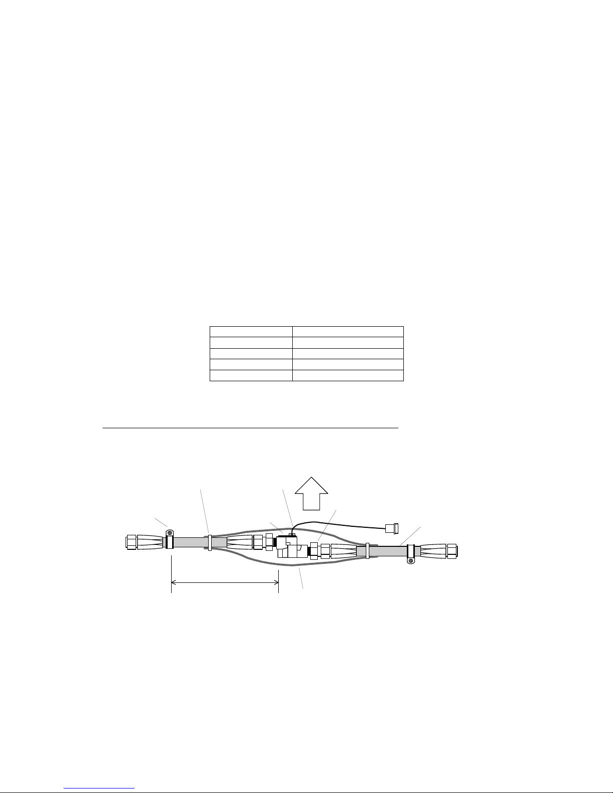
General Fuel Flow Transducer Installation
Use the J4 connector harness 700708 labeled FFSIG (white), FFPWR (red), and FFGND (black). If no previous fuel
flow transducer is installed, install transducer per
The EDM-900/930 receives signal from any installed FloScan Transducer with the following FloScan P/N’s
embossed on to the top of the transducer. The K-Factor is marked on the side of the Transducer and on a white
ticket. Wire per drawing 790744, Route the JPI wires along the existing wiring bundle lacing every foot.
The EDM is approved to work with the following Shadin equivalent PN.
FloScan PN Shadin equivalent PN
201-A NA
201-B 680501/680600
201-C NA
231 680503
Before connecting any hoses to the transducer, thoroughly clean them and insure they are free of any loose
material. Never pass air pressure through the transducer or use Teflon tape/pipe cement; damage will
occur. Use only steel fittings supplied never use aluminum fittings on transducer. Remove the transducer cap plugs
only when ready to install the hoses. Note the direction of fuel flow marked on the transducer. Fuel must flow in this
direction. Reverse flow installations will read ½ the required flow. Mount the transducer with the three wires pointing
up. The K-factor is printed on the side of the transducer and on a tag. Write down the K-factor here for future
reference __________.
AeroquipFire Sleeve
AE102/62-24
Aeroquip
900591BClamp
IN
OUT
6 inches maximum from
support
to carburetor, flow
divider, or fuel
injector
from fuel tank,
throttle body or
engine driven fuel
pump.
MS 21919
Clamp as required
Fittings 1/4 NPT. Do NOT
use aluminum fittings
Aeroquip
303 hose
Transducer
Cut slit in fire sleeve
up
The EDM-900/930 fuel flow transducer receives signal from any installed 201 or 231 transducer with either of these
part numbers embossed on to the top of the transducer. For specific engine Installations see Appendix A
Report 503
Page 20

FAA Approved Installation Manual for the Report No 908
EDM-900 and EDM-930 Page 20 of 55 Rev I
Primary Engine Data Management System Date 1-18-2013
27. Fuel Level Sender Wiring Types
The EDM has the capability to interface to the aircraft’s fuel level system. It is also used to directly read the fuel
senders for fuel calibration (no other equipment is needed). To implement the EDM fuel tank gauge functionality,
the EDM is connected directly to the senders or in some cases to the aircraft’s fuel sender signal conditioner (for
example the Pennycap system typically found in Cessna). The EDM has the capability to process signals from
three types of sender signals: Resistive output, Voltage output or Frequency output. JPI provides the appropriate
interface hardware (the P5 harness and any associated signal conditioners) based on information you provided
when your order was placed. Once installation is completed, you will perform a fuel level calibration. The EDM
stores this calibration internally. NOTE: The fuel quantity function will not be available until this calibration
has been performed successfully.
28. Capacitive Sender Frequency Output Type Sender System
Although frequency output type senders are uncommon in certified aircraft, JPI supports this interface. The P5
harness has two 3 conductor cables labeled LEFT TNK and RT TANK that are connected directly to the left and
right senders. See the drawing below for basic connection information (only right tank shown for illustration
purposes). Final route the LEFT TNK and RT TANK cables as necessary, then crimp the female contacts onto each
cables GRN, BLK, RED wires, then insert them into the connector housing. Connect this to the sender’s cable
connector. Connect the white wire of the pod cable to the center insulated terminal on the sender, and the black
wire to the terminal mounted on the metal body on the sender. See illustration on following page.
29. Resistive Output Type Sender System (Float type, most common)
Locate the wires that run between the existing ships fuel gauges and the senders and disconnect them. For tanks
that have more than one sender, the wiring between the senders must be retained. Make sure the senders do not
have voltage on them before connecting to the EDM. Connect the EDM to the senders using the wire pairs coming
from the signal conditioner as shown below. Note that one pair is for MAIN and the other is for AUX. Connect the
‘SIG’ wire to the senders signal terminal (typically the center stud) and the ‘GND’ wire to the closest ground terminal
near or on that sender. See illustration on following page.
Page 21
FAA Approved Installation Manual for the Report No 908
EDM-900 and EDM-930 Page 21 of 55 Rev I
Primary Engine Data Management System Date 1-18-2013
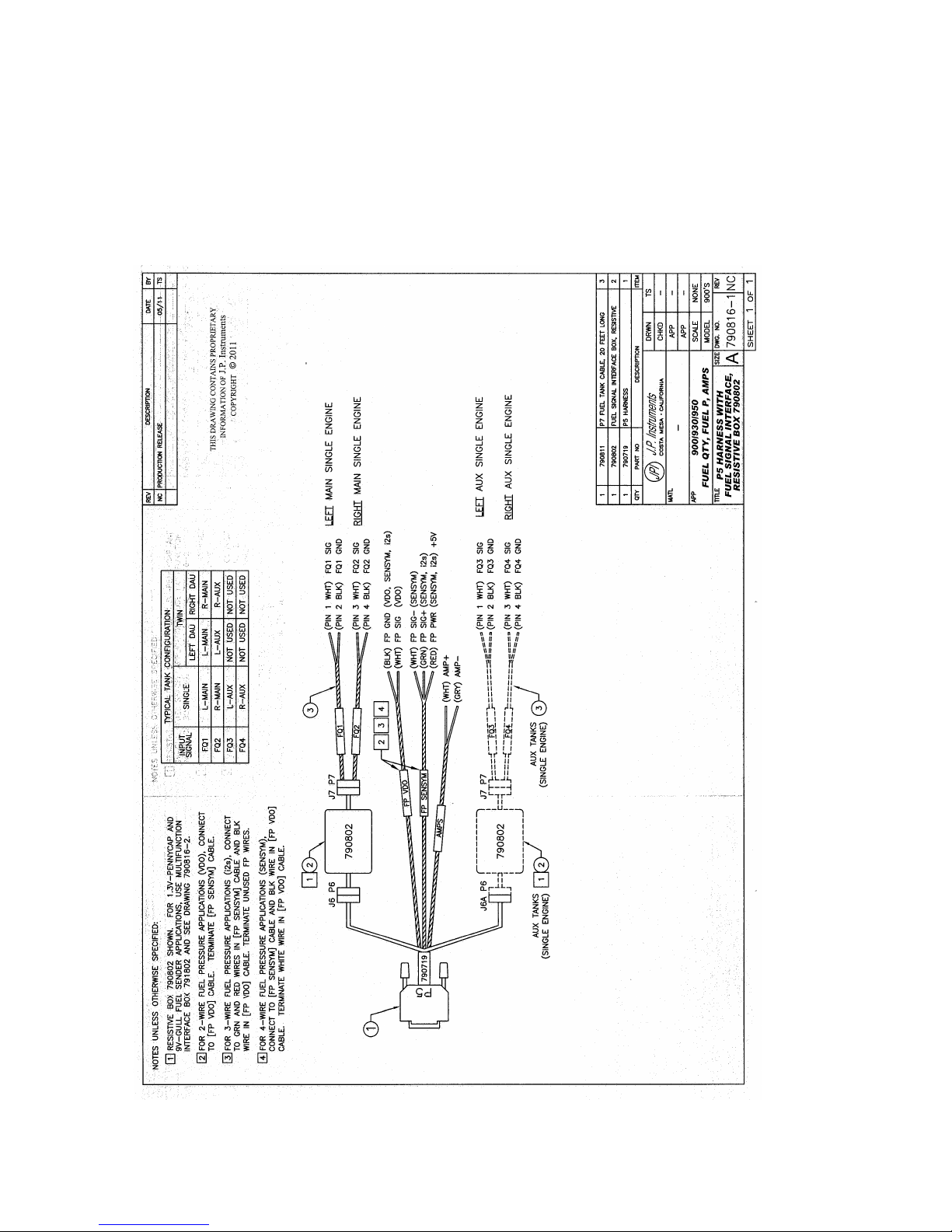
Example harness arrangement for an aircraft with resistive output senders
Resistive Harness PN 790719-3
Page 22

FAA Approved Installation Manual for the Report No 908
EDM-900 and EDM-930 Page 22 of 55 Rev I
Primary Engine Data Management System Date 1-18-2013
WARNING
:
Never add or remove fuel from the aircraft when the
master switch is turned on.
Fuel quantity gauge performance is affected by many
factors, such as the integrity of the sensor performance,
the accuracy of the calibration data you collected and
entered and most importantly your validation that the
EDM fuel quantity gauge is accurate and repeatable after
installation and calibration. You should not use the fuel
quantity gauge system for any flight related operations
until this validation criteria has been met.
30. Voltage Output Type Sender System
Voltage output type systems usually have a convertor box. This is typical with the ‘Pennycap’ brand capacitive
sender system. The Pennycap convertor box measures sender capacitance and converts it to a DC voltage output
signal for the aircrafts fuel level gauge. In some cases the Pennycap convertor box alternately monitors two tanks
per wing controlled by cockpit selector switch positions. This is typical for Cessna’s having 4 selectable tanks. The
EDM can interface to this system with the addition of the dashed interface hardware (PN 790802) shown below.
NOTE: This drawing is accurate for most models of the Pennycap system; however it is the installer’s responsibility
to verify proper connections to the Pennycap output signal.
31. Fuel Tank Calibration Setting Fuel Calibration Points
The EDM interfaces to various fuel level sensor types to facilitate direct reading of the fuel level in the aircraft fuel
tanks. The EDM has a multi-point fuel calibration table that you must enter. This table contains calibration values
(stored in non-volatile memory) used to translate sensor readings into the displayed fuel quantity values. The
calibration information is collected and recorded on paper for later entry into the EDM. NOTE: Fuel quantity gauges
will not be functional until the fuel calibration information has been entered into the EDM. You will use the EDM
instrument itself as the measuring device to collect calibration data.
The following describes the basic procedures necessary for collection and entry of data into the fuel level
calibration table. Note: Any changes to fuel table data will be temporary until you execute the ’SAVE’ function
(available after last cell of the last tank table is entered).
Before beginning the fuel table entry/edit process, you must have properly installed and tested for correct
functionality of the fuel sensors.
Page 23
FAA Approved Installation Manual for the Report No 908
EDM-900 and EDM-930 Page 23 of 55 Rev I
Primary Engine Data Management System Date 1-18-2013
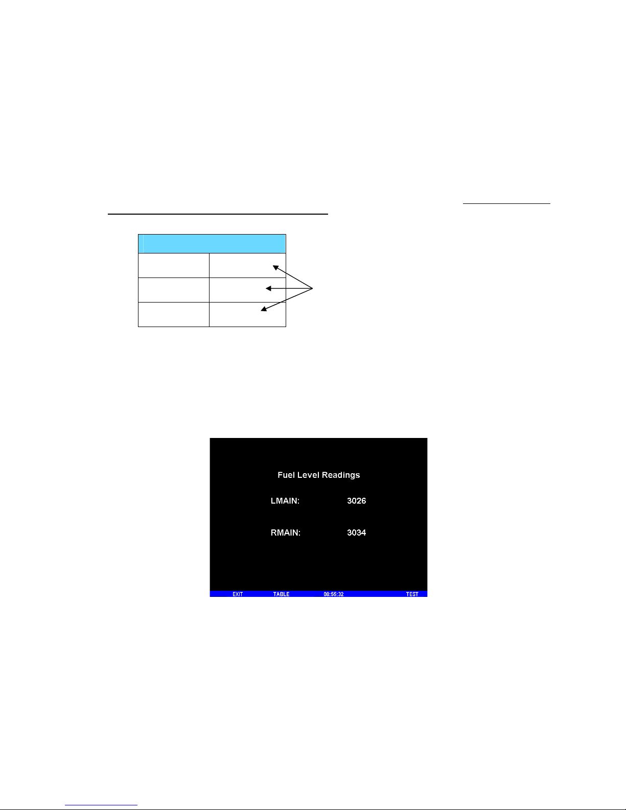
Getting Started…Collecting Fuel Level Calibration Data using the
EDM as a meter
.
1. With power off, hold in Button 4 (Button 1 being far left) and then turn on power. For each EDM
monitored tank, create a paper table with the desired number of calibration points (2 to 5) and at what
volume each will be. Number of calibration points to be entered into the system later. The zero gallon point
reading is always taken with unusable fuel in the tank. Example of a completed 3 point table for LEFT tank:
LEFT
F 39.0 GAL 1907
2 19.5 GAL 1154
E 0.0 GAL 685
2. This screen shown below provides real-time readings of all active fuel level sensors. Verify readings look
normal. Reading are arbitrary whole numbers
3. Now add fuel as needed to match the required volume for a particular point. Cycle power between readings
(hold in button 4), then take a reading and record it on paper adjacent to that point.
4. Repeat this process until all points, 2 to 5, have been recorded for each tank.
With AUX it would
say LMAIN and
LAUX
Actual Screen Shot
Readings
Page 24
FAA Approved Installation Manual for the Report No 908
EDM-900 and EDM-930 Page 24 of 55 Rev I
Primary Engine Data Management System Date 1-18-2013
32. After you have collected your data
After you have collected your data…Entering / Editing Fuel Level Calibration Data
The Fuel Table Editor is a spreadsheet type format allowing you to easily see the volume and related calibration
values side by side. You can easily navigate through the cells to enter values.
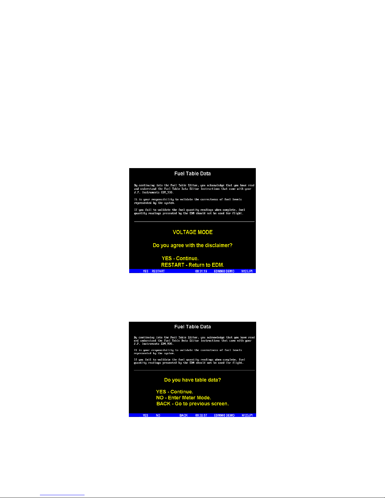
1. With power off, hold in Button 3 (Button 1 being far left) and then turn on power. Wait until you see ‘Do
you agree with the disclaimer?’. Tap YES if you agree and wish to continue.
2. Tap YES when you see ‘Do you have table data?’.
Page 25
FAA Approved Installation Manual for the Report No 908
EDM-900 and EDM-930 Page 25 of 55 Rev I
Primary Engine Data Management System Date 1-18-2013
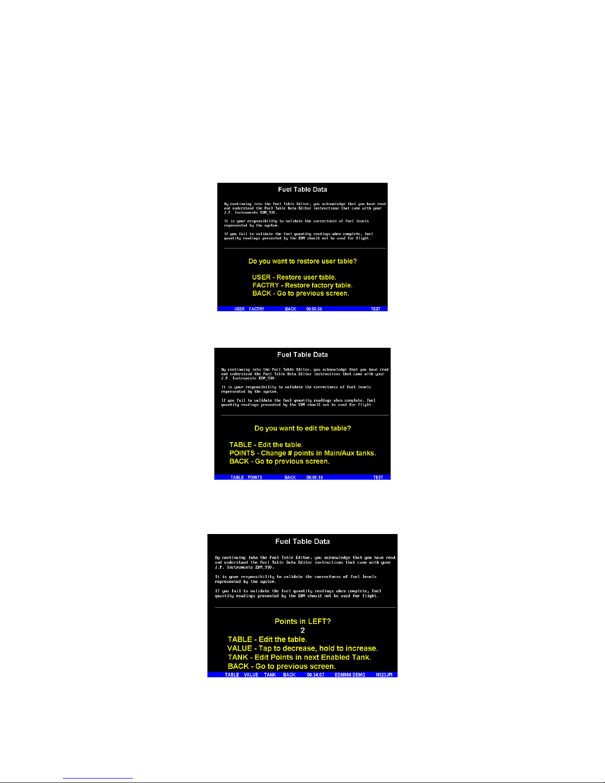
3. Tap USER when you see ‘Do you want to restore user table?’ (Note: tapping FACTORY
causes the fuel table stored on the Key Card to over-write any previous user entries in the fuel table. Use
FACTORY if you want to start from the original factory default).
4. Tap POINTS when you see ‘Do you want to edit the table?’.
5. You see ‘Points in LEFT’, the current calibration points for the LEFT tank.
6. Tap/hold VALUE to change to the desired number of calibration points for this tank (2 to 5). Each
Tank can have a different set of calibration points. So 5 points for Main and 2 points for Aux.
Page 26
FAA Approved Installation Manual for the Report No 908
EDM-900 and EDM-930 Page 26 of 55 Rev I
Primary Engine Data Management System Date 1-18-2013
7. Tap TANK to select the next active tank and repeat previous step. Continue until all tanks ‘points’ have
been set.
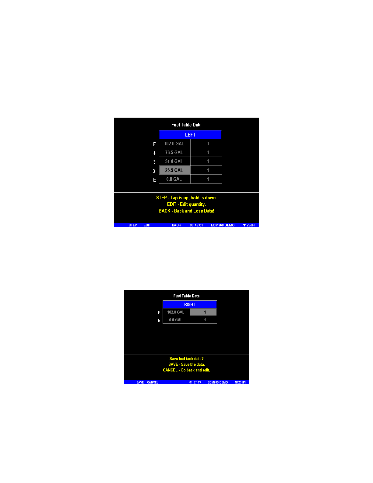
8. Tap TABLE. You see ‘Fuel Table Data’ ( White at top of screen) with a table. You may change any of the
fuel levels in the left column except for empty. You will enter the readings taken previously on paper into
the right column.
9. Tap/hold STEP to select the cell you want to edit. Tap EDIT to change the value. Tap or hold Modify to
change digit. Tap digit to change another part of the number.
10. Tap SAVE to record it. Follow the on-screen menus to edit the value. Repeat previous step until all tanks
data have been entered.
11. You see ‘Save fuel tank data?’. Answer SAVE to store all final data values or CANCEL to return to table
editing. To complete the process, tap SAVE a second time.
33. Fuel Flow Totalizer, Refuel Question
The fuel flow totalizer can be set to a different value than the fuel level tank size. To reprogram the “Refuel
setting for Main (total) and Auxiliary (total), enter the “Factory Program Mode” by holding buttons 1 and 2 in for a
few seconds until the display reads “Program”. Keep tapping next until you see “END”. Atthis point hold in button
Page 27
FAA Approved Installation Manual for the Report No 908
EDM-900 and EDM-930 Page 27 of 55 Rev I
Primary Engine Data Management System Date 1-18-2013
1 and 2 again until the display (5 sec.) changes and you see FACTORY . At this point you will see MAIN = XX.,
adjust with the “Plus and Minus buttons. Tap next for AUX=XX and adjust. Tap button twice to finish and save.
34. GPS Interface
Use the J4 connector harness 790708 labeled RS232 OUT TO GPS (white) and RS232 IN FROM GPS (gray).
Refer to the Manufactures GPS manual for the required pin connections on the GPS.
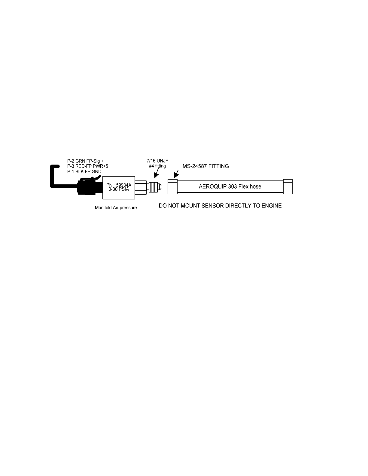
35. Manifold Pressure (MAP) Sensor
Page 28
FAA Approved Installation Manual for the Report No 908
EDM-900 and EDM-930 Page 28 of 55 Rev I
Primary Engine Data Management System Date 1-18-2013
36. RPM Sensor installation
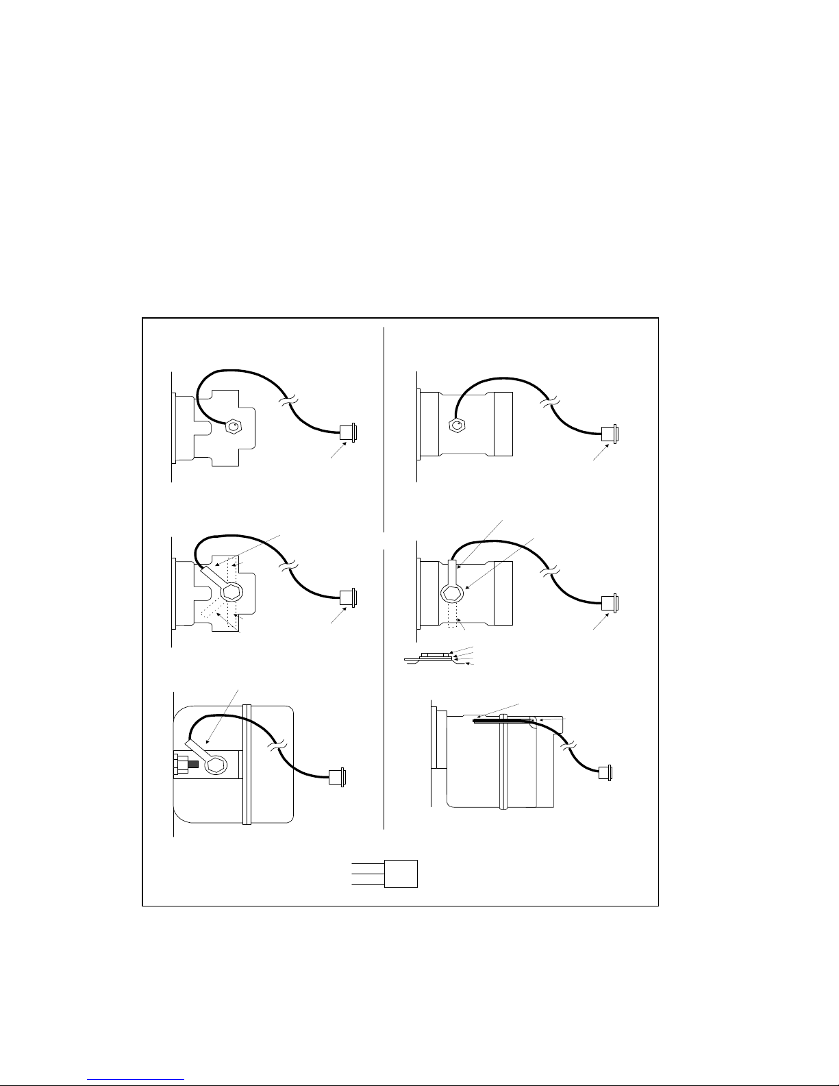
Use the J3 connector harness 790420 and connect the 3 leads using the supplied 3-pin connector and pins. There are
three types of magnetos commonly in use. You must have the correct RPM sensor for the magneto installed in the
aircraft. The following part numbers apply: Slick -4000, -6000 use JPI P/N 420815. For the Bendix -1200 use P/N
420815. Dual magnetos use JPI PN 420810. Mount the sensor as shown in the appropriate diagram below.
Slick
Magnetos
Mo unt senso r sid e of br ack et t ow ar ds
rev Mar 2004
Bendix
Magnetos
Bendix 1 200 series
pressurized
JP I 42 0 807
Co nn ec tor to h a rne ss
engine
Alt ern a te br acke t loc ation s
T
O
P
position lim it
position lim it
Mo unt sens or sid e of br ack et t ow ar ds
ma gnet o bo dy , pos itio ne d ov er th e ma gn et
arm a tur
e
Co nn ec to r to har ne ss
Slick 6 000, 4000 series
non-p ressurized
JP I 42 0815-1
engine
Co nn ec to r to har ne ss
Slick 6000, 4000 series
pressu rized
JP I 42 0809
engine
TOP
Se nsor rin g mu nt ed und er ve nt plu g .
Ste m a t r igh t an gle s to ma gneto cente r line
ma gn et o
bo dy
Alt ern a te br acke t loc ation
Ve nt plug
Sp ac er rin g
Se ns or rin g bra ck et
Ma gn et o body
engi
ne
Slick 600
series
Se ns or mus t b e
ove r
mo ving m ag ne t
arm a ture
Re move this
scr ew
to mo un t
se nsor
bra ck
et
Bendix -20, -21, -200, 1200 series
non-pressurized
JP I 42 0 815-2
Co nn ec tor to h a rne ss
engine
Bendix D ual
Magneto
engine
Mo unt senso r sid e of br ack et t ow ar ds
ma gn et o
body
T
O
P
RP M SIG GRN
RP M G ND BL K
RP M PW R RED
1
Page 29

FAA Approved Installation Manual for the Report No 908
EDM-900 and EDM-930 Page 29 of 55 Rev I
Primary Engine Data Management System Date 1-18-2013
37. EDM-900/930 Specifications and Limitations
The following parameters must be customized for the aircraft into which the EDM-900/930 is installed.
Factory set limits or default values for EDM-900/930
1. TIT 1650 F TSO-C43
2. CHT 450 F TSO-C43
3. Oil Temp Low 90 F TSO-C43
4. Oil Temp HI 230F TSO-C43
5. Oil Press low 15 psi TSO-47
6. Oil Press Hi 100 psi TSO-47
7. Vacuum 0- 15”hg TSO-47
8. RPM 2700 Limit and range TSO-C49
9. RPM set to cyl 6 TSO-C49
10. Map 32 In hg HI TSO-C45
11. Map setting 29.90 In Hg TSO-C45
12. Fuel Pressure Hi 35 psi Injected TSO-47
13. Fuel Pressure Lo 15 psi Injected TSO-47
14. Fuel Pressure Hi 8 psi Carb TSO-47
15. Fuel Pressure Lo .5 psi Carb TSO-47
16. Fuel Flow 24 GPH TSO-C44
17. K-factor 29.99
18. Carburetor filter smoothing 1
19. Ammeter configuration (load or charge-discharge). Load NON TSO
20. HC-120 (% of HP) NON TSO
21. Fuel Level Resistive/Capacitive TSO-55
22. Low fuel 10 Gal
23. Low time 45 Min
24. Main tank 75 gallons
25. Aux tank 0
26. GPS set at GARMIN
27. Diff 500 degrees TSO-C43
28. CLD 60 degrees per minute TSO-C43
29. Amps limit 100 amps NON TSO
30. Record time, 6 sec intervals NON TSO
31. Hobbs on at 1000 RPM NON TSO
On 14 vdc systems during start-up the EDM may reset it self. This is normal due to extremely low battery voltage.
The conditions and test required for TSO approval of this article are minimum performance standards. It is the
responsibility of those desiring to install this article either on or within a specific type or class of aircraft to determine
that the aircraft installation conditions are within the TSO standards. The article may be installed only if installation of
the article is approved by the Administrator. The functions of Volts, Amps, and Horse Power were tested to DO-160D
and DO-178B, but not TSO’d since no TSO exist for these functions. Deviation granted for TSO-C49b to include digital
display and sensor. All TSO required probes, transmitters and sensors also tested to DO-160D.
Page 30

FAA Approved Installation Manual for the Report No 908
EDM-900 and EDM-930 Page 30 of 55 Rev I
Primary Engine Data Management System Date 1-18-2013
38. EMI Radio Test and functional check:
Even through the EDM-900/930 has been tested to DO-160E Section 20 (EMI) the installation itself could creates radio
interference on specific frequencies. The following test is to insure that this does not exist.
EMI/RFI TESTS: perform tests, in accordance to the table below, to insure wire routing and connectivity has not
compromised the signal integrity of the NAV/COM receivers. Power up the aircraft bus (or buses) in accordance with
normal engine prestart procedures (see Aircraft Pilot Operating Handbook). Verify that the EDM-900/930 is operating
normally and there are no bad probes or alarm messages. Set the frequency and audio panel to listen to that radio.
Loud buzzing/humming is considered ‘unusual noise’ in the context of these tests also the OBS needle should not
move. Should any EMI noise be found that is attributed to the EDM-900/930 system, it must be corrected by shielding
and/or rerouting wiring to eliminate the noise. If unusual noise is heard, remove power from the EDM-900/930 system
to check if it is the source of this noise. If the EDM-900/930 system is not the source of ‘unusual noise’ then mark the
table with a ‘PASS’.
Frequency NAV/COM 1
(PASS/FAIL)
NAV/COM 2
(PASS/FAIL)
Comments
108.00
112.00
115.00
117.00
120.00
121.00
122.00
123.00
124.00
125.00
126.00
127.00
128.00
129.00
130.00
132.00
Page 31

FAA Approved Installation Manual for the Report No 908
EDM-900 and EDM-930 Page 31 of 55 Rev I
Primary Engine Data Management System Date 1-18-2013
39. Component Parts
Twin engine
-4 Cyl -6 Cyl -7 Cyl -8 Cyl -9 Cyl
Display EDM-930 P/N 790000-C-(xxx) 1 1 1 1 1
Display EDM-900 P/N 790000-A-(xxx) 1 1 1 1 1
EGT probe KIT PN 11800 8 12 14 16 18
TIT probe with option KIT 12000 1 1 1 1 1
CHT probe KIT PN 12600 8 12 14 16 18
OAT probe with option KIT 12200 1 1 1 1 1
IAT probe with option KIT 11200 1 1 1 1 1
Carb temp probe KIT 11900 1 1 1 1 1
Oil Temp probe with option KIT 12500 PN 500409 1 1 1 1 1
Oil pressure sender KIT 14600 PN 159936A 1 1 1 1 1
Fuel pressure sender KIT 14500 PN 159935A 1 1 1 1 1
Fuel pressure differential sender Kit 14800 PN 159938 1 1 1 1 1
Ammeter shunt KIT 13000 PN 159920 1 1 1 1 1
Fuel Flow transducer PN 700900-1 1 1 1 1 1
Fuel Level sender option 1 1 1 1 1
MAP KIT 14400 PN 159934A 1 1 1 1 1
RPM one of P/N 420815-1 or,-2 1 1 1 1 1
RAD P/N-790749 1 1 1 1 1
Component Parts List for EGT (KIT 12800), TIT (KIT 12000) Probe
1 Thermocouple type K probe PN M-111
1 Stainless Steel Clamp Thimble
1 Stainless Steel Exhaust Seal Washer
1 Stainless Steel Screw Type Clamp
2 Ring Terminals
2 Screws and nuts 6-32 X 1/4
1 Fiberglass tube 3/8” x 5”
Component Parts list for CHT KIT 12600
1 Bayonet Probe Thermocouple type K Spring loaded PN 5050-T
1 Or Gasket thermocouple probe type K PN MM-113
2 Ring Terminals
2 Screws and Nuts 6-32 X 1/4"
1 Fiberglass tube 3/8” x 5”
Component Parts list for IAT (KIT 11400) probe
1 Thermocouple type K probe PN M-111
1 Stainless Steel Clamp &Thimble
1 Stainless Steel Exhaust Seal Washer
Component Parts list for OAT (KIT 1220) probe
1 P/N 400510, OAT probe
2 Ring Terminals
2 Screws and Nuts 6-32 X1/4"
Fiberglass tube 3/8” x 5”
Component Parts list for CARB (KIT 11900) probe
1 P/N 400128, CARB probe
2 Ring Terminals
2 Screws and Nuts 6-32 X1/4"
Page 32
FAA Approved Installation Manual for the Report No 908
EDM-900 and EDM-930 Page 32 of 55 Rev I
Primary Engine Data Management System Date 1-18-2013
1 Fiberglass tube 3/8” x 5”
Component Parts list for OIL Temperature probe (KIT 12500)
1 P/N 400509 OIL probe
1 AN900-10 crush washer
2 Ring Terminals
2 Screws and Nuts 6-32 X 1/4"
1 Fiberglass tube 3/8” x 5”
Component Parts list for Kit 14800 Differential Fuel Pressure (only if required by POH)
1 P/N 159938 Fuel pressure sensor
1 P/N 159961 Clamp, Loop Cushioned
1 P/N 174204 Connector MS 3116F8-4S
Component Parts list for Oil Pressure sensor KIT 12400
1 P/N 159936A Oil Pressure sensor
1 P/N 159961 Clamp, Loop Cushioned
1 P/N 174402 Connector Pack 3 Pin and Terminals
Component Parts list for Fuel Pressure Sensor KIT 14500 (only if required by POH)
1 P/N 159935A Fuel pressure sensor
1 P/N 159961 Clamp, Loop Cushioned
1 P/N 174402 Connector Pack 3 Pin and Terminals
Component Parts list for ampere shunt
1 P/N 159920 100 amp shunt
2 Ring Terminals
Component Parts list for Fuel Flow Transducer
1 fuel flow transducer, 201 or 231 PN 700900-1,-2
8 inches of 1.5” dia. fire sleeve
1 3-pin connector housing
3 female pins
2 AN816-4-4 fittings (Continental) or AN816-4-6 (Lycoming)
Component Parts list for MAP sensor KIT 14400
1 P/N 159934A Manifold pressure sensor
1 P/N 159961 Clamp, Loop Cushioned
1 P/N 174402 Connector Pack 3 Pin and Terminals
Components Parts list for RPM sensor P/N depends on Magneto make and model
Bendix magneto -20,120………….P/N 420815-2
Slick magneto 4000 or 6000………P/N 420815-1
40. Weight and Balance Data
Indicator PN 790000(-A) EDM-900 2.0 Lbs
Indicator PN 790000(-C) EDM-930 3.0 Lbs
EGT / TIT / CDT / IAT / OAT probe 2.0 oz. each / 0.125 lbs
CHT / Oil Temperature probe 1.5 oz. each / 0.094 lbs
4/6 Cylinder Harness 8 ft. 14.0 oz. each / 0.88 lbs
RPM 1.5 oz each / .094 lbs
MAP 5.0 oz / 0.42 lbs
Fuel Pressure Sender 5.0 oz / 0.42 lbs
Oil Pressure Sender 5.0 oz / 0.42 lbs
Harness each 1.0 Lbs
Page 33
FAA Approved Installation Manual for the Report No 908
EDM-900 and EDM-930 Page 33 of 55 Rev I
Primary Engine Data Management System Date 1-18-2013
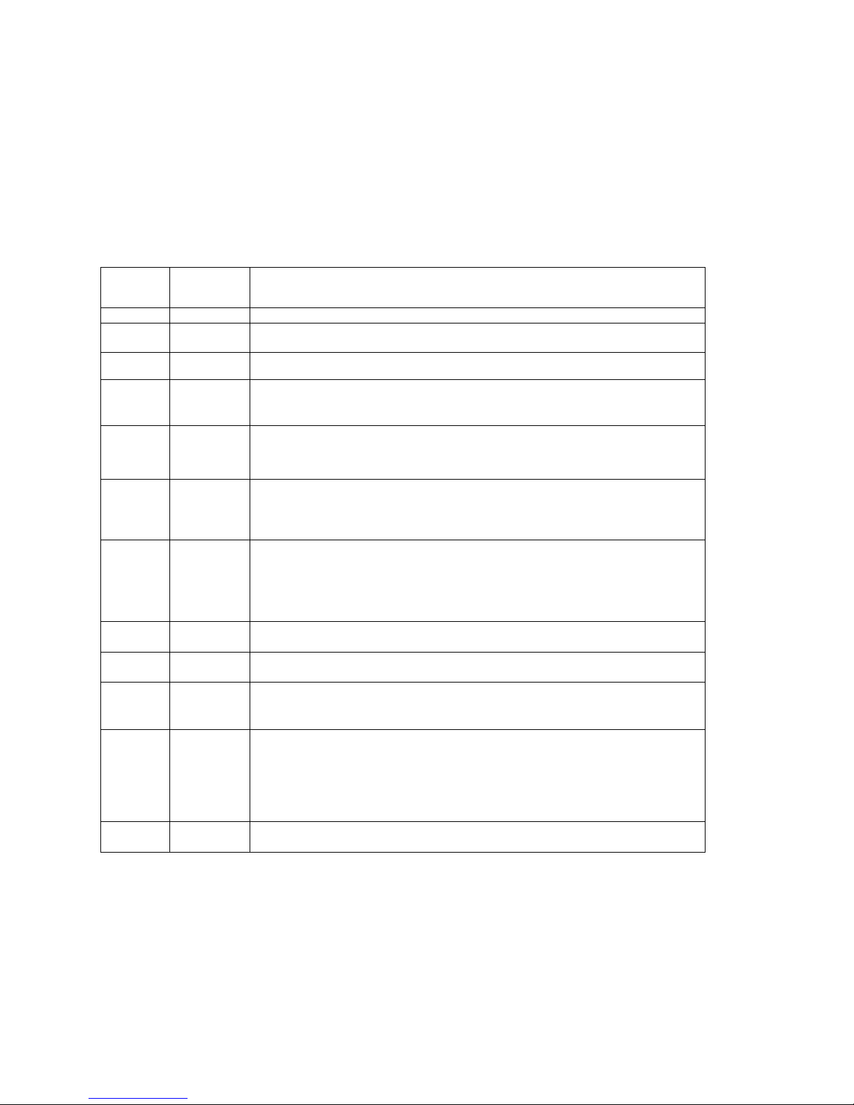
41. Pilot Programming
To start the Pilot Program procedure, simultaneously hold the STEP and LF buttons for five seconds. You will see the
word PROGRAM for two seconds and then the sequence shown in the chart below.
Tap the STEP button to advance to the next item in the list. Hold the STEP button to step back to the previous item.
Tap the LF button to select alternate values of that item. Simultaneously hold both STEP and LF to exit.
STEP
advances
next item
LF sequences
through these
values
Comments
PROGRAM
Stays on for two seconds.
FUEL
N
FILL ?
N
Tap LF to change fuel status. Exits program mode when done.
RATE 4 0 … 9
Index rate (pause time in seconds) in the Automatic Mode. 0 disables the Automatic
Mode.
OAT F OAT
F
OAT
C
To calibrate the OAT 10°, hold both the STEP and LF buttons simultaneously for five
seconds, which will proceed to the next step. Otherwise the next step will be skipped.
OAT0
OAT-
I0 …
OATI0
This step will be normally be skipped.
Adjust the indicated temperature up or down by up to 10°. For example, OAT3
adjust the OAT 3° higher.
EGT
I?N
EGT
I?N
EGT
I?Y
Y—Yes—sets the digital display to one-degree resolution; N—No—sets 10°. (10°
resolution is easier to interpret the EGT’s.)
HPC
I25
70 HP
HPC=
I25
%HP display will change when HP constant is adjusted. Hold STEP and LF for 5
seconds until you see ADJUST to set the HP calibration. Tap STEP to continue to the
next step.
To adjust the MAP, hold both the STEP and LF buttons simultaneously for five
seconds, which will proceed to the next step. Otherwise the next step will be skipped.
MAP
29.9
MAP 20
32
Adjust the MAP.
KP
29.90
Adjust the instrument’s K-factor to match the fuel flow transducer K-factor.
TR IP?NTR IP? N
TR IP? Y
N—No—Upon informing the EDM that you refueled the aircraft, reset total fuel used to
0.
Y—Yes—accumulate total fuel used rather than reset to 0 at each refueling. See page
HOBS
VAL
2424
ENG
25
EDM
3567
FRM
Displays the engine hours and airframe hours.
END?
Y
END? Y
STEP exits the pilot programming mode.
LF reenters pilot programming mode.
42. Programming the HP Constant
You must adjust the HP Constant once for your aircraft. You must perform this adjustment in the air while the aircraft is
in flight between 5,000 and 8,000 feet MSL.
1. Enter the pilot program mode by simultaneously holding the STEP and LF buttons for five seconds.
2. Tap STEP repeatedly until you see—for example— HPC = I25. Then hold both the STEP and LF buttons display
until you see ADJUST, followed by HPC= I25. The adjustment range for the HP Constant is 45 to 180.
3. Set the MP and RPM per your POH to 70 percent power. Let conditions stabilize.
Page 34

FAA Approved Installation Manual for the Report No 908
EDM-900 and EDM-930 Page 34 of 55 Rev I
Primary Engine Data Management System Date 1-18-2013
4. Change the HP reading on the EDM-900 to 70 percent by adjusting the HP constant in the lower display by holding
or tapping the LF button. Percent HP should be close to 100 percent during takeoff at sea level.
5. Tap the STEP button to proceed to the next step.
43. Selecting Fuel Pressure Type (EDM-900 only)
To properly display Fuel Pressure values, the EDM must be told what type of Fuel Pressure sensor is connected to the
EDM. This is normally set at the factory for new installations. To set or modify the type of Fuel Pressure sensor
connected to the EDM, follow these steps:
1. Enter Pilot Program Mode by holding the STEP and LF buttons for 5 seconds
2. When the EDM enters Program Mode, tap the button labeled “NEXT” until END? Is displayed in the scanner
message area.
3. Again hold the STEP and LF buttons until the EDM enters Factory Program Mode.
4. After “Factory” is displayed in the scanner message area, tap the NEXT button until FUEL PRESSURE = is
displayed in the scanner message area.
5. Hold the STEP and LF buttons until the word ADJUST appears in the message area
6. Tap the PLUS or MINUS buttons to change the selected Fuel Pressure sensor type.
7. To save the selected value, hold the STEP and LF buttons until the word SET appears in the message area.
8. Tap the STEP button repeatedly until the message END? is displayed in the message area
9. Tap the button labeled YES to save changes and restart the EDM.
44. Customizing Non-Primary Data (EDM900 only)
You can customize – change or re-order non-primary data channels in the non-primary portion of the EDM display
(non-primary values are displayed as text gauges without redline values – See Pilot’s Guide for more information).
Non-primary data channels are numbered from 1 up to 6, depending on your particular aircraft configuration and EDM
installation. To customize the LCD layout of non-primary data, follow these steps:
1. Enter Pilot Program Mode by holding the STEP and LF buttons for 5 seconds
2. When the EDM enters Program Mode, tap the button labeled “NEXT” until END? Is displayed in the scanner
message area.
3. Again hold the STEP and LF buttons until the EDM enters Factory Program Mode.
4. After “Factory” is displayed in the scanner message area, tap the NEXT button until CUSTOMIZE DISPLAY?
is displayed in the scanner message area.
5. Hold the STEP and LF buttons until the word ADJUST appears in the message area
6. You will see a prompt like “1=VOLTS” (or similar). This describes the data channel to be displayed in the first
non-primary data location.
7. Tap the “CHANGE” button to change to the next non-primary data channel. The new data channel selected
will be displayed in the
8. Tap the “NEXT” button to select the next non-primary location (such as 2=AMPS).
10. When all changes have been made, hold the STEP and LF buttons until the word SET appears in the
message area.
11. Tap the STEP button repeatedly until the message END? is displayed in the message area
12. Tap the button labeled YES to save changes and restart the EDM.
45. K Factor
The K factor is shown on the fuel flow transducer as a four-digit number, which is the number of pulses generated per
gallon of fuel flow. Before installing the transducer, write down the K factor here _________. To enter the number,
move the decimal point three places to the left. For example if the K factor on the fuel flow transducer is 29,123, enter
29.12 in the K factor parameter.
Page 35

FAA Approved Installation Manual for the Report No 908
EDM-900 and EDM-930 Page 35 of 55 Rev I
Primary Engine Data Management System Date 1-18-2013
If the K factor is increased, the indicated fuel flow will decrease, and vice-versa. When the K factor is changed during a
trip, calculations of fuel used, fuel remaining and time to empty are not retroactively recalculated.
Page 36

FAA Approved Installation Manual for the Report No 908
EDM-900 and EDM-930 Page 36 of 55 Rev I
Primary Engine Data Management System Date 1-18-2013
Fine tuning the K Factor
The K factor shown on the fuel flow transducer does not take into account your aircraft’s particular installation. Fuel
hose diameters and lengths, elbows, fittings and routing can cause the true K factor to be different from that shown on
the fuel flow transducer.
You must use the following procedure to fine tune the K factor.
1. Make at least three flights of about two to three hours each. Note the actual fuel used (as determined by topping
the tanks) and the EDM-900 calculation of the fuel used for each flight USD.
Flight
Fuel USED shown by EDM
(total tank - REM) Actual fuel used by topping tanks
1
2
3
Total
2. Total the EDM-900 calculated fuel used and the actual fuel used.
3. Record the current K factor here ____________________ and in the table below.
4. Calculate the New K factor as follows:
New K factor = (EDM fuel used) x (Current K factor)
(actual fuel used)
New K factor = ( ) x ( )
( )
Every time you fine tune the K factor, change it by only half of the amount calculated above, and record the
measurements here:
Date
EDM
fuel used
actual
fuel used
Current
K factor
New K factor
=x/
Pilot’s
initials
Page 37

FAA Approved Installation Manual for the Report No 908
EDM-900 and EDM-930 Page 37 of 55 Rev I
Primary Engine Data Management System Date 1-18-2013
46. Adjusting the K Factor
This procedure is different than for setting other parameters.
1. If you haven’t already done so, start the Pilot Program Mode by clearing all alarms by tapping step repeatedly,
then simultaneously hold the STEP and LF buttons (for about five seconds), until you see the word PROGRAM,
followed by ‘FUEL ? N’.
2. Tap STEP repeatedly until you see K-FACTOR=29.90 (this value may be different on your unit).
3. Hold both the STEP and LF buttons simultaneously until a digit begins flashing. This indicates editing has been
enabled.
4. Tap or hold the LF button to change the flashing digit to the desired value.
5. Tap or hold the STEP button to select the next digit to edit.
6. Repeat steps 4 and 5 until the displayed value is set to your desired value.
7. To save new value, hold STEP and LF buttons simultaneously (for about five seconds) until the K factor parameter
exits.
8. Tap STEP repeatedly until you see END ? Y, then Tap STEP once more to exit the Pilot Program Mode.
47. Programming Accumulate Trip Total
Accumulate—default is OFF: resets the fuel used to 0 every time you inform the EDM-900 that the aircraft was
refueled. With accumulate ON fuel used will not be reset to 0 when you inform the EDM-900 that the aircraft was
refueled.
Select “No” if you wish to display total fuel used since the last time you informed the EDM-900 that the aircraft was
refueled. Select “Yes” to display total fuel used for an extended trip with multiple fuel stops. This selection affects only
the USD measurement.
During normal operation, to reset the accumulated fuel used display at any time, tap STEP until you see USD. Hold
both STEP and LF until the display shows .0 USD.
Page 38

FAA Approved Installation Manual for the Report No 908
EDM-900 and EDM-930 Page 38 of 55 Rev I
Primary Engine Data Management System Date 1-18-2013
48. Trouble Shooting
Diagnostic Testing on Startup and During Flight
When your EDM is first turned on it tests internal components, calibration and integrity of the probes.
During flight, probes are constantly checked for inconsistent or intermittent signals.
Problem
Situation Correction
A MISSING COLUMN IN THE
DISPLAY UPON START UP
diagnostic routine has found an open line
or probe with no connection.
Replace the EGT or CHT probe shown
in the error message
A MISSING COLUMN IN THE
DISPLAY DURING FLIGHT
a reading that is jumping around or
incorrect
The probe is removed from the line up
Replace the EGT or CHT probe shown
in the error message on the next flight.
DISPLAY FREEZES OR MAY
BE INCORRECT
A power transient could cause the
processors to malfunction
Recycle the power to the EDM
LEANFIND FINDS A “PEAK”
TOO SOON
Failure to pre-lean before performing
LeanFind or stopping while leaning.
Leaning too slowly
Continue to lean without stopping
Lean more rapidly
PEAK NOT FOUND DURING
LEANFIND
Lean Find not activated or stopping while
leaning
Lean at the speed of approximately
10°F per second
OFF-SCALE EGT COLUMNS,
TOO HIGH OR LOW
Off-scale EGT column readings. EDM in
the Normalize view (blue EGT scales).
Return to Standard mode by holding
the LF button.
FIRST CYLINDER TO PEAK
IS NOT THE HOTTEST
The first to cylinder peak is not necessarily
the hottest
This is normal.
EGTS RISE DURING SINGLE
MAGNETO CHECK
Incomplete combustion persisting longer This is normal.
EGTS NOT UNIFORM
DURING LOW POWER
OPERATION
Fuel and air distribution is not optimal at
low power settings
This is normal.
0.0 GPH
Zero’s indicate Fuel flow is too low to
register
This is normal.
--- GPH
Dashes indicate No fuel flow transducer
signals
Have the mechanic verify if it is the
sensor or wiring.
--- H.M
Dashes indicate No fuel flow transducer
signals
No GPS signal, check the wiring
OPEN PRB
Open probe. Wiring to probe is open circuit. Check
wiring and crimps. Swap probes to
troubleshoot.
BAD-PRB
Bad probe. Erratic reading. May be poor electrical
connection. Swap probes to
troubleshoot.
RED ‘X’ DRAWN THROUGH
A SINGLE GAUGE
Measurement out of range. Have the mechanic verify if it is the
engine or the sensor. Replace as
necessary.
RED ‘X’ DRAWN THROUGH
ALL GAUGES FOR AN
ENGINE
DAU failure or DAU communications error. Check power to DAU and wiring
harness connections.
CAL ERR
Calibration error. Return unit to factory.
DSP XXX
Internal communication error. Return unit to factory.
COMM ERR
Internal communication error. Return unit to factory.
NO I 5 MV
Calibration error. Return unit to factory.
Page 39

FAA Approved Installation Manual for the Report No 908
EDM-900 and EDM-930 Page 39 of 55 Rev I
Primary Engine Data Management System Date 1-18-2013
NO 50MV
Calibration error. Return unit to factory.
NO 2.5V
Calibration error. Return unit to factory.
WARNCAL, WARNCFG
Transient warning messages. Return unit to factory.
HOBSERR
The time of the most recent flight may not
be reflected in the HOBBS meter.
Return unit to factory.
HOBSBAD
The HOBBS data has been corrupted. Return unit to factory.
HANGCFG, HANGCAL
Internal system errors. Return unit to factory.
48.1 GPS Interface Diagnostics
Problem
Situation Correction
Measurements ‘xxx REQ’,
‘XXX RES’ AND ‘XXX
MPG’ are all missing from
the scan.
No communications from GPS receiver to
EDM.
No connection or aircraft GPS is off.
NO - COM message and
‘xxx REQ’, ‘XXX RES’ AND
‘XXX MPG’ are all missing
from the scan.
Communications are received by EDM and
the Auto-Protocol setup is in process.
Verify correct output format setup in
GPS receiver; check GPS
connections.
NO - SIG message and
‘xxx REQ’, ‘XXX RES’ AND
‘XXX MPG’ are all missing
from the scan.
GPS receiver has insufficient signal for
valid data.
Check GPS signal
NO - WPT message and
‘xxx REQ’, ‘XXX RES’ are
all missing from the scan.
No waypoints are programmed into the
aircraft GPS receiver.
Program way points
Page 40
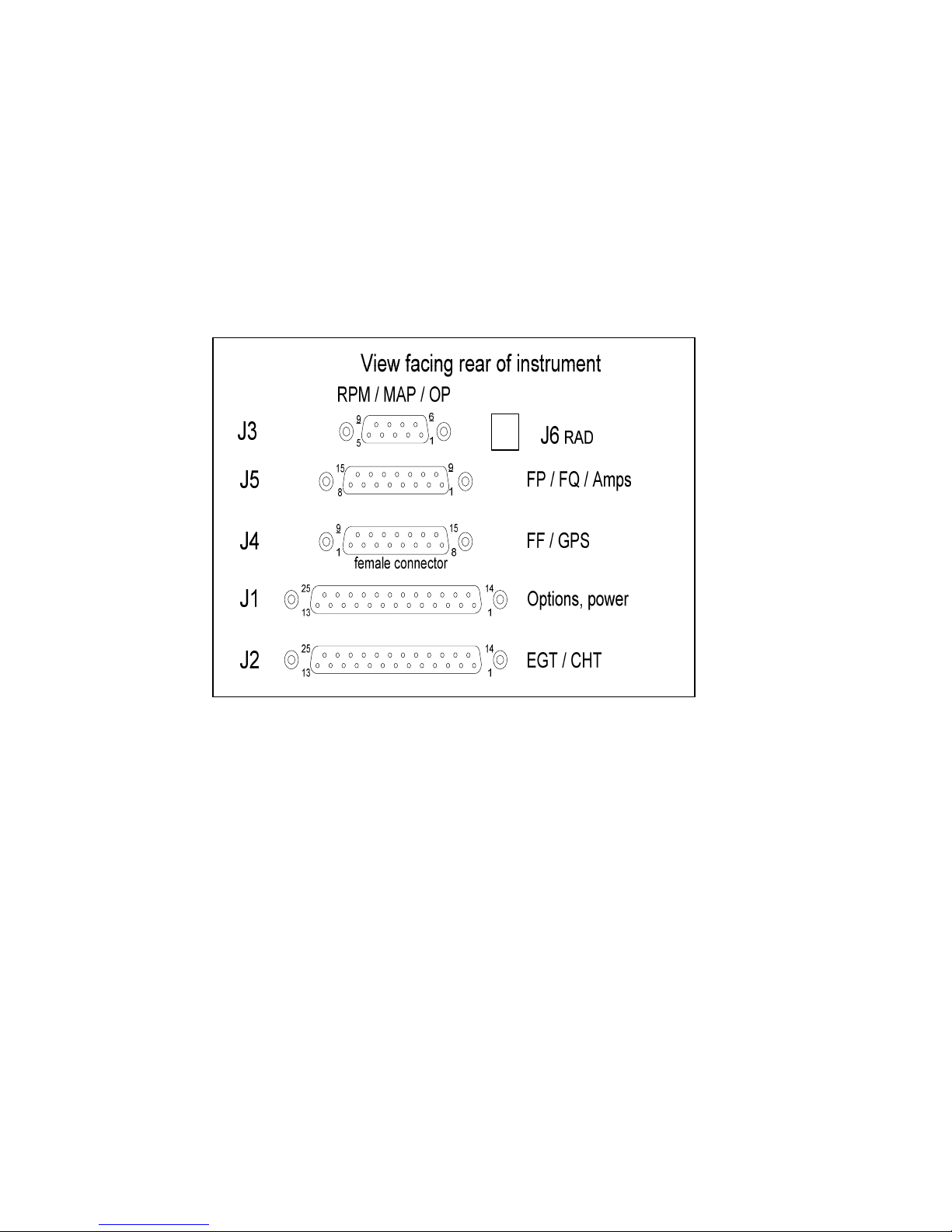
FAA Approved Installation Manual for the Report No 908
EDM-900 and EDM-930 Page 40 of 55 Rev I
Primary Engine Data Management System Date 1-18-2013
49. Connector Pin Assignments on EDM, J1 through J5
Rear view of EDM 930 Showing Connector Locations
Page 41
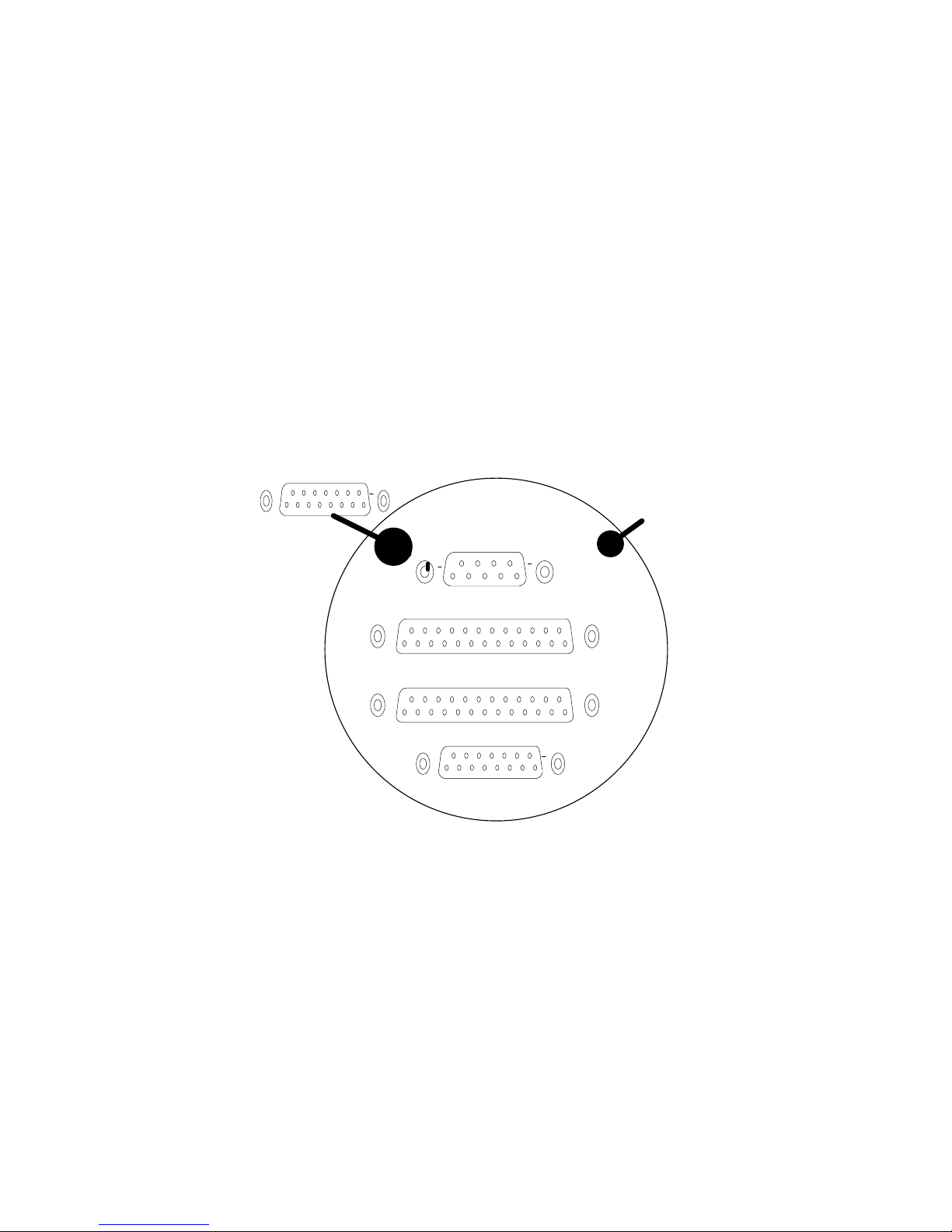
FAA Approved Installation Manual for the Report No 908
EDM-900 and EDM-930 Page 41 of 55 Rev I
Primary Engine Data Management System Date 1-18-2013
50. Connector Pin Assignments on EDM, J1 through J5
Rear view of EDM 900 Showing Connector Locations
6
1
9
5
9
1
15
8
14
1
25
13
14
1
25
13
P3
P1
P2
P4
9
1
15
8
P5
Alert Light
Page 42
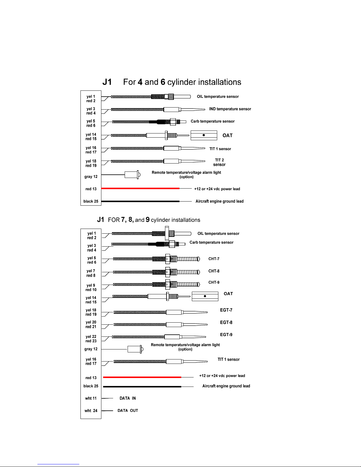
FAA Approved Installation Manual for the Report No 908
EDM-900 and EDM-930 Page 42 of 55 Rev I
Primary Engine Data Management System Date 1-18-2013
Page 43
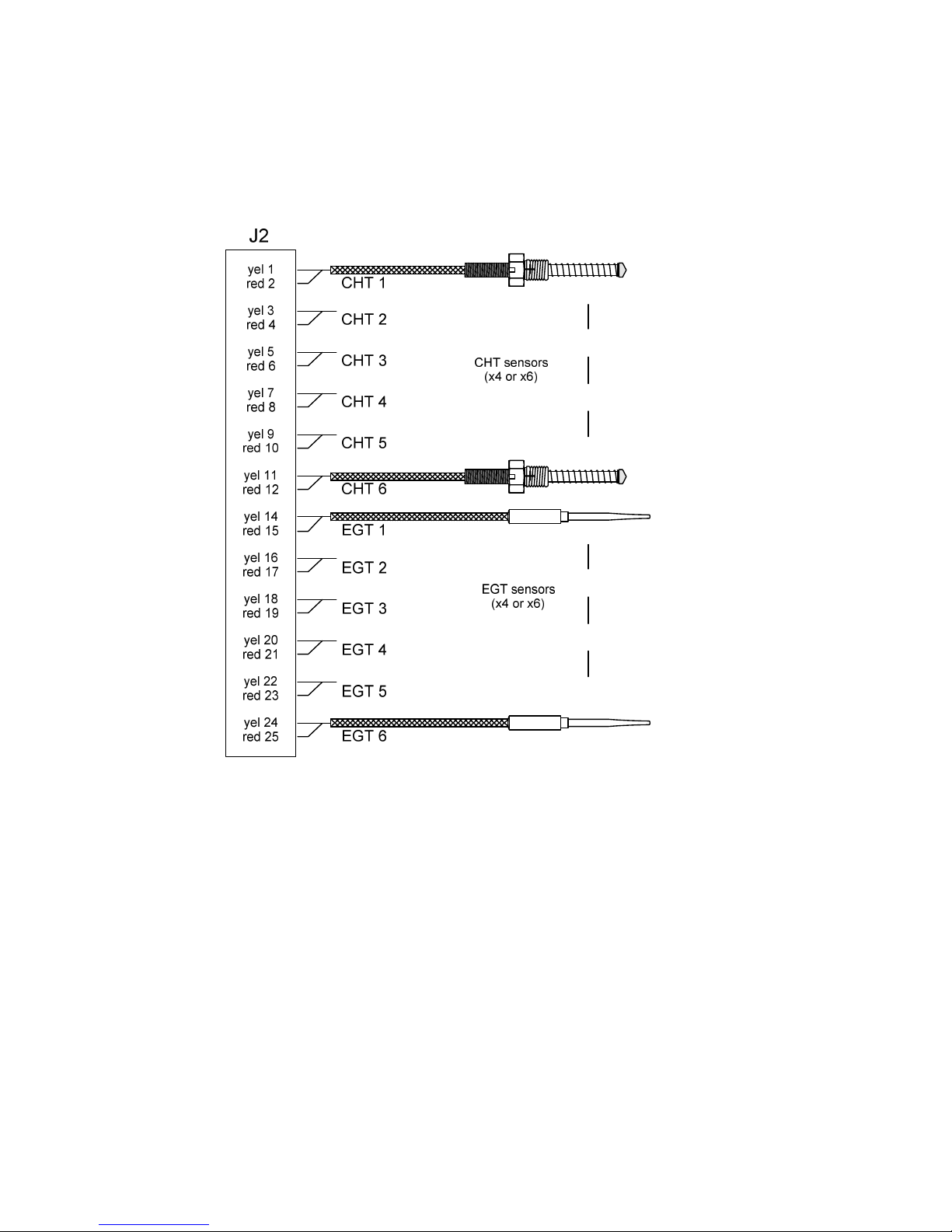
FAA Approved Installation Manual for the Report No 908
EDM-900 and EDM-930 Page 43 of 55 Rev I
Primary Engine Data Management System Date 1-18-2013
Page 44
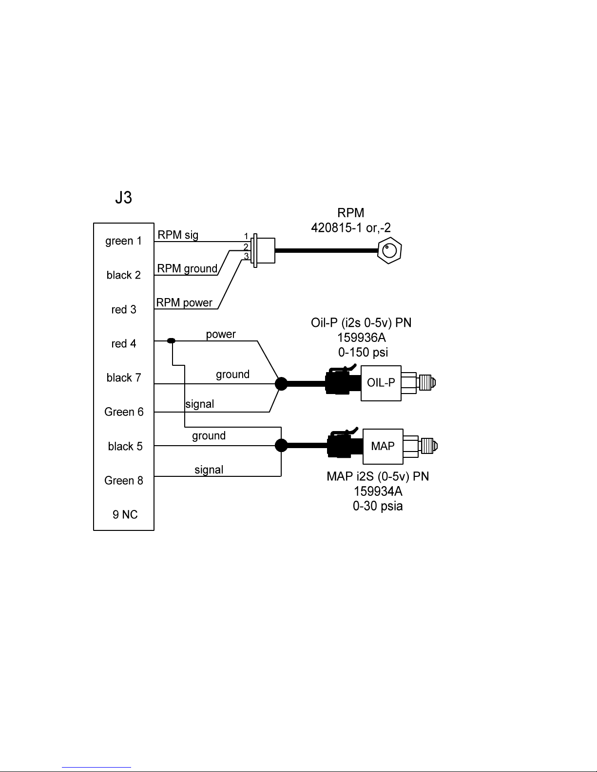
FAA Approved Installation Manual for the Report No 908
EDM-900 and EDM-930 Page 44 of 55 Rev I
Primary Engine Data Management System Date 1-18-2013
51. J3 RPM, MP, Oil-P
J-3 Harness with i2s Oil and manifold pressure sender
Page 45
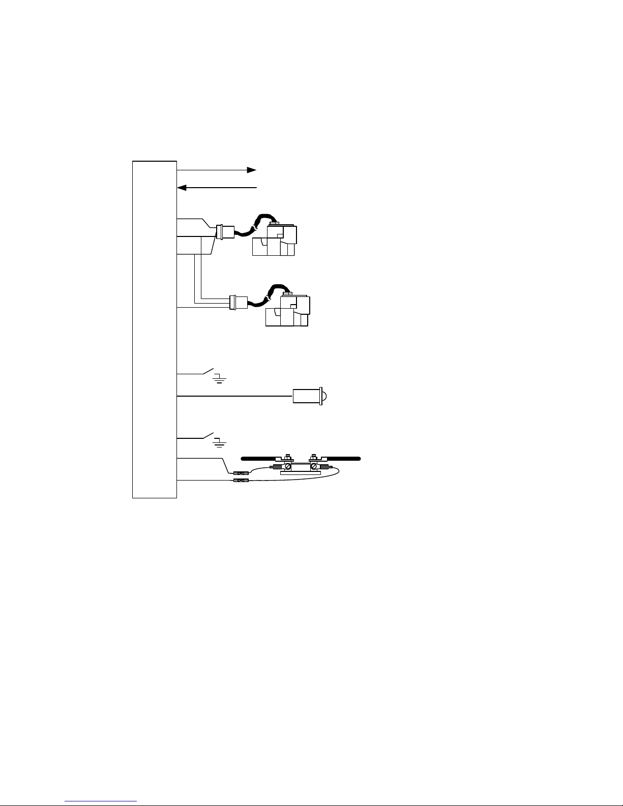
FAA Approved Installation Manual for the Report No 908
EDM-900 and EDM-930 Page 45 of 55 Rev I
Primary Engine Data Management System Date 1-18-2013
+
Data out to GPS
Data in from GPS
IN
OUT
Main FF 700900-1, (201) -2 (231)
White 1
Gray 2
white 4
red 5
black 6
NC 9
White 12
10
11
13
White 14
Gray 15
Remote fuel flow alarm light (option)
IN
OUT
FF2
Power and ground connect
to pins 5 and 6 respectively
5 6
Right low
fuel switch
Left low
fuel switch
AMPS 2
159920
J4 (FF, GPS, AMP 2 )
Return FF 700900-1, (201) -2 (231)
Optional
Optional
optional
Serial communications
Page 46
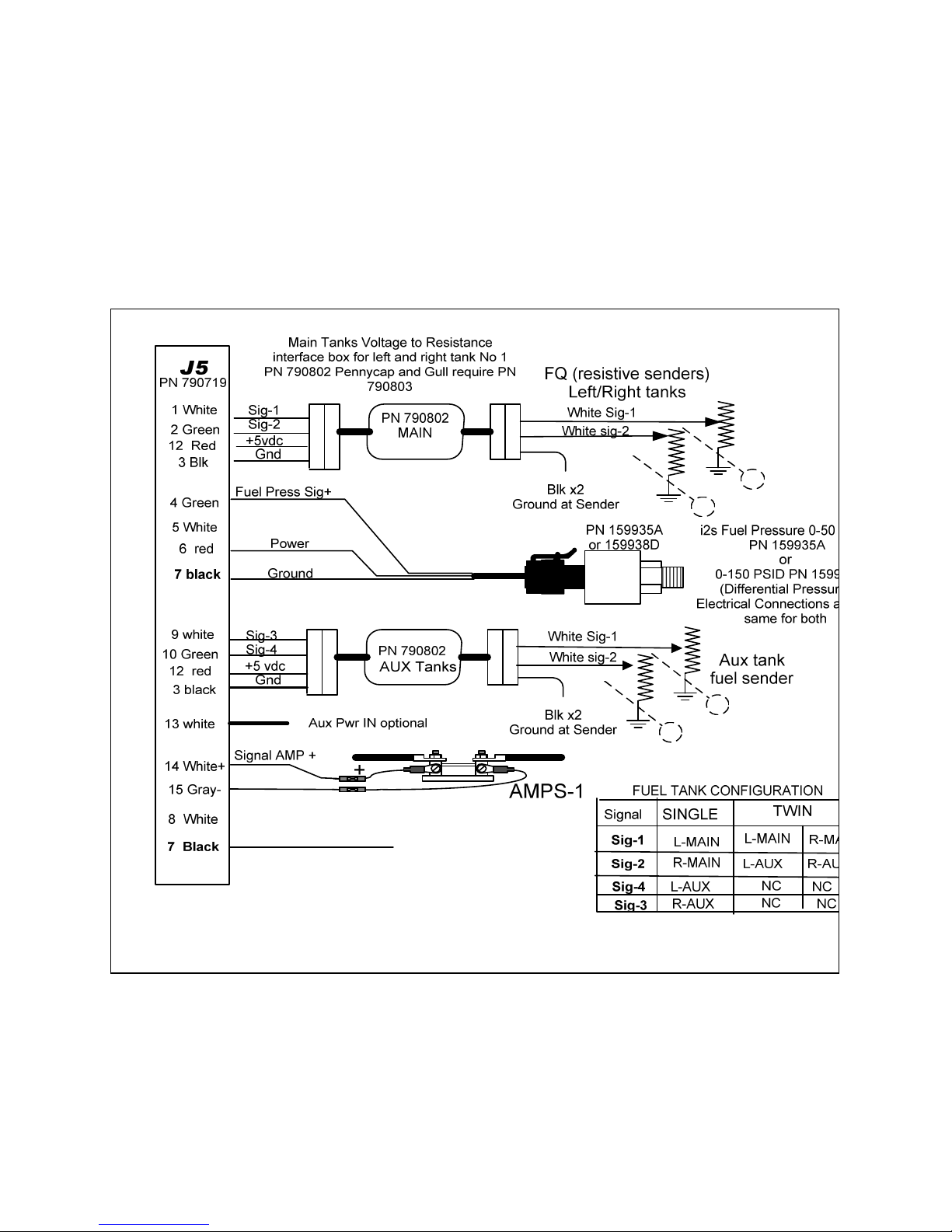
FAA Approved Installation Manual for the Report No 908
EDM-900 and EDM-930 Page 46 of 55 Rev I
Primary Engine Data Management System Date 1-18-2013
51.1 J5 PN 790719 (fuel tanks, fuel press, amps)
J-5 Harness with i2s fuel pressure sender.
1.
Page 47
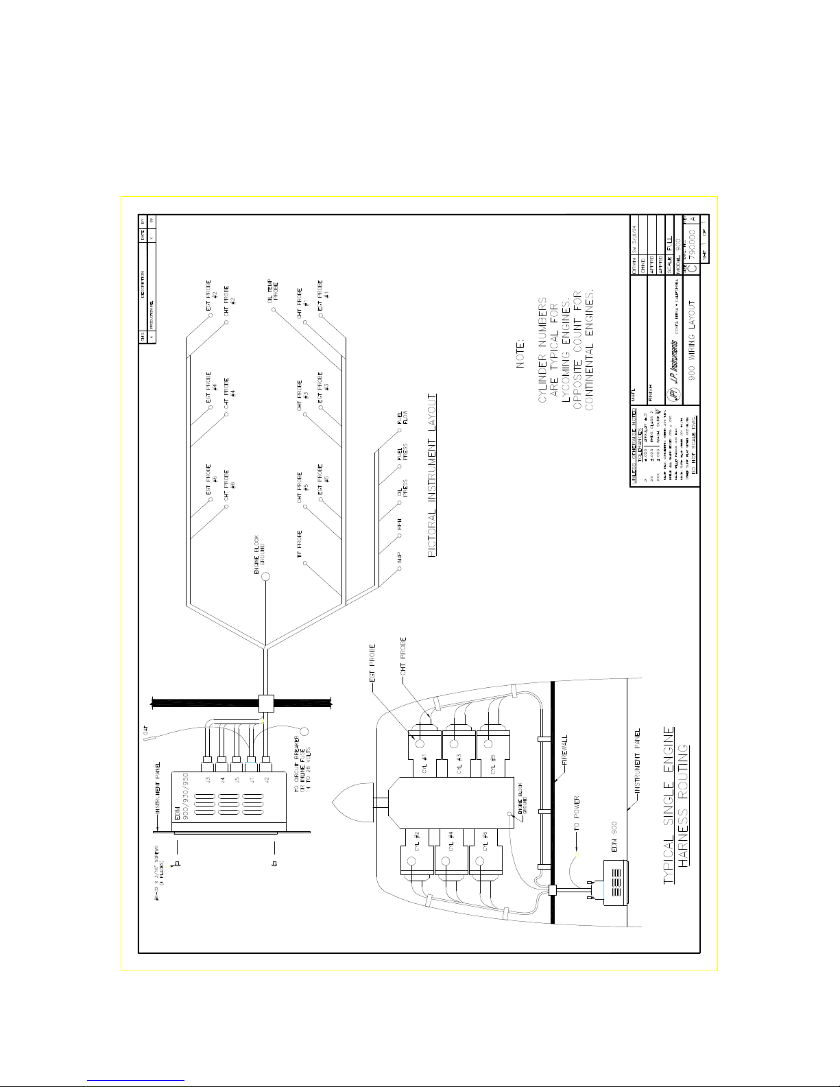
FAA Approved Installation Manual for the Report No 908
EDM-900 and EDM-930 Page 47 of 55 Rev I
Primary Engine Data Management System Date 1-18-2013
Page 48

FAA Approved Installation Manual for the Report No 908
EDM-900 and EDM-930 Page 48 of 55 Rev I
Primary Engine Data Management System Date 1-18-2013
52. Appendix A Fuel Flow install Report 503
See attached Report
53. Appendix B ICA
See attached Report
Page 49
FAA Approved Installation Manual for the Report No 908
EDM-900 and EDM-930 Page 49 of 55 Rev I
Primary Engine Data Management System Date 1-18-2013
54. Appendix C Connector Pin Assignments on EDM, J1-J2 Only with ARINC 429
J1 - DB25M
Production
Version
1
Oil Temp Y
2
Oil Temp R
3
Spare RS232 Data In
Not used
4
FDR RS232 Data Out
To Flight Data
Recorder
5
Ground Oil Pr/Hydr Pr
6
Oil Pr +input 0-5V
7
Oil/Hydr Pr +5V power
8
Torque +5V power
9
Torque +input 0-5V
10
Torque Ground
11
AMPS #1+
connected to
generator shunt
12
AMPS #2+
connected to
battery shunt
13
14-28V Pwr (BAT1)
14
OAT Y
15
OAT R
16
ITT Y
17
ITT R
18
Emerg Hyd Pr +in 0-5V
Kg (5V) / lb (0V)
Select
19
Main Hyd Pr +in 0-5V
Day (5V) / Night
(0V) Select
20
Fuel Pr +5V power
21
Fuel Pr +input 0-5V
22
Fuel Pr Gnd
23
AMPS #1 -
connected to
generator shunt
24
AMPS #2 -
connected to
battery shunt
25
Power Ground
J2 DB25F Production Version
1
ARINC IN #1A
Not used
2
ARINC IN #1B
Not used
3
GPS RS232 Data In
4
GPS RS232 Data Out
5
Fuel Flow Signal
6
Fuel Flow +12V pwr
7
Fuel Flow Ground
8
FQ #1 0-5V
9
FQ #2 0-5V
10
Fuel Temp RTD -
Ground
11
Fuel Temp RTD +
12
nCAL
Do Not
Connect
13
14-28V Aux Pwr (BAT2)
14
ARINC OUT #1A
15
ARINC OUT #1B
16
Annunciator #1
Ground = on
17
Annunciator #2
18
Annunciator #3
19
Annunciator #4
20
FQ #3 0-5V
21
FQ #4 0-5V
22
N2, Np
23
N1, N2 Gnd
24
N1, Ng
25
Power Ground
Page 50

Appendix B
J. P Instruments Inc.
PO Box 7033
Huntington Beach CA 92646 ICA Supplement No. 905-01
Rev. D date 7-15-12
INSTRUCTIONS FOR CONTINUED AIRWORTHINESS (ICA)
EDM-900/930 PRIMARY ENGINE DATA MANAGEMENT SYSTEMS
For
Aircraft as listed on STC SA01435SE
This Supplement must be attached to the FAA Approved Installation Manual when the
J.P. Instruments EDM-900/930 is installed in accordance with Supplemental Type
Certificate SA01435SE.
Before performing any procedures contained in this manual
the user should verify they have the latest ICA revision.
Please check web site at www.JPITech.com
for the latest revision of this manual.
The registered owner on file at JPI will also be notified of any changes.
Page 51

FAA Approved Installation Manual for the Report No 908
EDM-900 and EDM-930 Page 51 of 55 Rev I
Primary Engine Data Management System Date 10-9-2012
Revisions For ICA:
Revisio
n
Date Description
Affected Pages
IR 12/ 15 /2011
Complete Document
1 thru 6
A 2/07/2012
Added Penetration of Aircraft Pressure Vessel
item 9
Page 5
B 4/23/2012 Revised items 5 and 9 Page 5
C 5/16/2012 Deleted old items 3 and 12. Revised old items 4,
5, 8, and 14 (new items 3, 4, 7, and 13
Pages 5 and 6
D 7/15/2012 Clarified acronyms in item 2. Corrected
typographical errors in revision log, items 2, 4,
5, 6, and 7. Reworded items 4 and 14 for clarity.
Added Rev. D to all pages.
Pages 1 through
6
Page 52

FAA Approved Installation Manual for the Report No 908
EDM-900 and EDM-930 Page 52 of 55 Rev I
Primary Engine Data Management System Date 10-9-2012
1- Introduction:
The EDM-900/930 is a combined electronic indicating system which simultaneously displays to the pilot powerplant
and aircraft systems operating parameters. It includes the following indicating systems; replacing all previous
primary digital and/or analog instruments: Message Area Abbreviation for primary and non-primary instruments is
shown on the Right with the function on the left .
2- Description:
Display
Non-primary functions Induction air temperature
(IAT), carburetor inlet temperature (CARB), exhaust
gas temperature (EGT) span (DIFF), bus voltage,
amperage load, Shock Cooling (CLD), Fuel
Remaining (REM), Fuel Required (WP REQ), Fuel
Reserve (WP RES), Nautical Miles per Gallon
(MPG), Estimated Time to Empty and Fuel Used
have programmable alarm limits. Engine Cylinder
head Temperature (CHT), Exhaust Gas
Temperature (EGT), Fuel Pressure (FP), Fuel Flow
(FF), and Engine Manifold Pressure (MAP) may not
be primary on some installations. Any non-primary
functions are programmable.
The right hand side the EDM-900 has horizontal
tape scales with digital values below each scale and
the EDM-930 right side has vertical scale columns
with a digital value below each column. The
functions are: Oil-Temperature (OT), oil-pressure
(OP), fuel-pressure (FP), CDT for engine
installations having a primary compressor discharge
temperature, Fuel Flow (FF), and two main and two
aux. fuel tank quantities (QTY-LF/RT Main, QTYLF/RT Aux). The engine rotational speed (RPM) and
manifold pressure (MAP) are presented in the upper
left corner of the instrument. The EGT, CHT and
turbine inlet temperature (TIT) are presented in the
lower left corner. Below the EGT/CHT columns is a
message center that displays the digital values of
the EGT/CHT/TIT and additional functions like
shock cooling and caution and limit alarm
messages. OAT is displayed in its own box in
degrees C or F. With the EDM-930 having a fixed
display the EDM-900 can rotate 90 degrees to
accommodate installation.
Specific values for each parameter are displayed
digitally above the vertical scale displays of EGT,
CHT, and TIT or TIT-R,-L. The highlighted number
below the columns indicates which cylinder's digital
information is presently displayed as an alarm in the message center or when manually
or automatically stepping through the parameters.
Gauge Function
Message Area
Alarm Abbreviation
Primary
Primary
Engine rotational speed RPM xxxx
Engine Manifold Pressure MAP xx.x in hg
Engine Cylinder Head Temp CHTX xxxoF
Engine Oil Temperature
OT xxx
o
F
Engine Oil Pressure OP xxoF
Fuel Pressure FP xx PSI
Fuel Flow to engine FF xx.x GPH
Comp. Discharge Temp. CDT xxxoF
Turbine inlet Temp. Left side TIT-L xxxxoF
Turbine Inlet Temp. Right side TIT-R xxxxoF
Single Turbine Inlet Temp. TIT xxxxoF
Non-Primary Non-Primary
Exhaust Gas Temp. EGTXxxxxoF
EGT Span, highest to lowest EGT (a
calculated number)
DIFF xxxoF
Induction Air Temperature IAT xxxoF
Carburetor Air Temperature CARB xxxoF
Shock Cooling of CHT CLD xxo/MIN
Differential Temp. of EGT DIF xxoF
Bus Voltage Volts xx.x
Amperage Load AMPS xx
Outside Air Temp. OAT xxoF, oC
Estimated Time to Empty Est. T to E xx:xx H:M
Fuel used to date USED xx.x GAL
Estimated Remaining fuel Est. REM xx GAL
Estimated Fuel required to Waypoint Est. WP REQ xx GAL
Estimated Fuel Remaining at
Waypoint
Est. WP RES xx GAL
Nautical Miles per Gallon ECON xx.x MPG
Brightness, Dim control DIM/BRT
Page 53

FAA Approved Installation Manual for the Report No 908
EDM-900 and EDM-930 Page 53 of 55 Rev I
Primary Engine Data Management System Date 10-9-2012
Programming
Depressing the LF and STEP buttons simultaneously enters the program mode to enter fuel quantities, display
scan rate, OAT display to °F or °C, EGT digital display resolution to 1 or 10° and other setup parameters. Exit by
depressing STEP. If either the STEP or LF buttons are not pushed for three minutes and the rate is not “0”, the
EDM-900/930 will revert to automatic scan mode. Depressing the STEP button will stop the automatic mode and
revert to manual mode. Refer to the EDM-930 Pilot’s Guide Rev. C or later for additional operating information.
EDM- 930 Remote Alarm Display (RAD)and EDM-900 Remote Annunciator Light (RAL) The
RAD for the EDM-930 is a 0.2” high, 8 character independent display and for the EDM-900 the RAL is a
combination Red/Yellow light. The RAD or RAL will still function if the main display is inoperable. On the EDM-900
and EDM-930 only primary instrument alarms are indicated.
The RAD or RAL is located in front of the pilot within the primary flight instruments and displays caution and limit
exceedance when any of the parameters has reached its preset trigger point. On initial startup or whenever power
is turned on, the words “EDM-930 PRIMARY” is displayed, followed by the make and model of the aircraft for which
the primary limits are set.
Alarm Limits
Whenever a parameter reaches the programmed caution trigger point, the main display will flash. Tapping the
STEP button extinguishes these warnings.
Similarly, whenever a parameter reaches a programmed limit value, the display and the RAD will flash. Tapping the
STEP button will extinguish the red display warnings on the main display but the RAD will also continue to flash the
acronym until the parameter is not at or beyond the limit value.
Primary alarm limits for each specific aircraft model are set by JPI and are not programmable by the pilot. These
include some or all of the following: CHT, CDT, EGT, O-T, O-P, F-P, QTY-LF, QTY-RT, MAP, RPM, FF, CARB,
and TIT. The primary functions for your installation are shown on the Primary label on the back of the instrument
and are identical to those specified in the FAA Approved Airplane Flight Manual/Pilot’s Operating Handbook (POH).
For caution alarms, primary digits and acronyms are flashed in amber at the original manufacturer’s published
caution points or, if none is specified, at a specific temperature below the programmed limit.
When a caution range is reached, the pilot can momentarily depress the STEP button to extinguish the particular
flashing alarm. If another parameter has also reached its limit, that label will then begin to flash. The pilot should
continue to monitor the affected functions as he would if a conventional analog display had reached a limit. The bar
graph functions of CHT, EGT, and TIT remain displayed at all times
Alarm priority list.
21. OILP_LO.
22. FP_LO.
23. OILT_HI.
24. CHT.
25. TIT.
26. FLVL. (Fuel Level)
27. REM.
28. FP_HI.
29. MAP.
30. DIF.
31. CLD.
32. RPM.
33. OILT_LO.
34. VOLTS.
35. OILP_HI.
36. AMPS.
37. CDT.
38. RES.
39. EGT.
40. FF.
Dimming
Automatic dimming is provided to dim both the panel display and the remote alarm. Dimming can also be
accomplished manually. Tapping the far right hand button (labeled Dim) decreases brightness. Continuously
holding this button increases brightness. Manual dimming overrides the automatic dimming feature. When
switching electrical power off and on, the system defaults to automatic dimming.
Page 54

FAA Approved Installation Manual for the Report No 908
EDM-900 and EDM-930 Page 54 of 55 Rev I
Primary Engine Data Management System Date 10-9-2012
3- Servicing Information:
There are no field adjustments or calibration requirements after initial installation for the J. P. Instruments EDM
900/930. After initial installation follow the maintenance instructions of the ICA to replace failed components.
4- Maintenance Instructions:
Visually inspect wiring and all other EDM-900 series components on installation and during scheduled 100 hour
and/or annual inspections (as applicable) for damage, wear, and security. Repair or replace wiring as needed and
replace components in accordance with the EDM 900/930 Installation Manual, Report No. 908 Rev H or higher,
Sections 7 through 43. Repair of thermocouple wiring is not allowed. Damaged thermocouple wiring must be
replaced.
Maintenance of nonfunctioning or malfunctioning components may only be done at the JPI factory.
5- Troubleshooting Information:
Troubleshooting information can be found in section 42 of the EDM 900/930 Installation Manual, Report No. 908
Rev H or higher.
6- Removal and Replacement Information:
Refer to the EDM 900/930 Installation Manual, Report No. 908 Rev H or higher, for the specific part/system in
question. The removal of the system or sensor is the reverse of the installation instructions.
If the unit is removed and reinstalled, a functional check of the equipment must be conducted (see Section 30 of
EDM 900/930 Installation Manual, Report No 908 Rev H or higher).
7- Diagrams:
Refer to the EDM900/930 Installation Manual Report No 908 Rev H or higher Section 43 for wiring diagrams.
8- Special Inspection Requirements:
NONE
Page 55

FAA Approved Installation Manual for the Report No 908
EDM-900 and EDM-930 Page 55 of 55 Rev I
Primary Engine Data Management System Date 10-9-2012
9- Application of Protective Treatments:
Not applicable to this system.
10- Data:
Not applicable to this system.
11- List of Special Tools:
Not applicable to this system.
12- Recommended Overhaul Periods:
There are no recommended overhaul periods for this system.
13- Airworthiness Limitations:
None.
The Airworthiness Limitation section is FAA approved and specifies maintenance required under §§ 43.16 and
91.403 of the Federal Aviation Regulations unless an alternative program has been FAA approved.
14- Revision:
These Instructions for Continued Airworthiness have been reviewed and accepted by the FAA. In the event that a
revision is required the revision will be submitted to the FAA for review and acceptance. Before performing any
procedures contained in the manual the user should verify they have the latest revision by Checking the web site at
www.JPITech.com for the latest revision of this manual. Owners of record will also be notified by mail or e-mail of a
revision update. The revised Instructions for Continued Airworthiness must become a part of the aircraft records
and a logbook entry made noting the revision
 Loading...