

Page 1
JP FLUID CONTROL
MANUAL-SMD-720-EN v1.2 www.jpfluidcontrol.com 1
SMD-720
ANALOG TIMER
Analog Timer (SMD-720) Manual
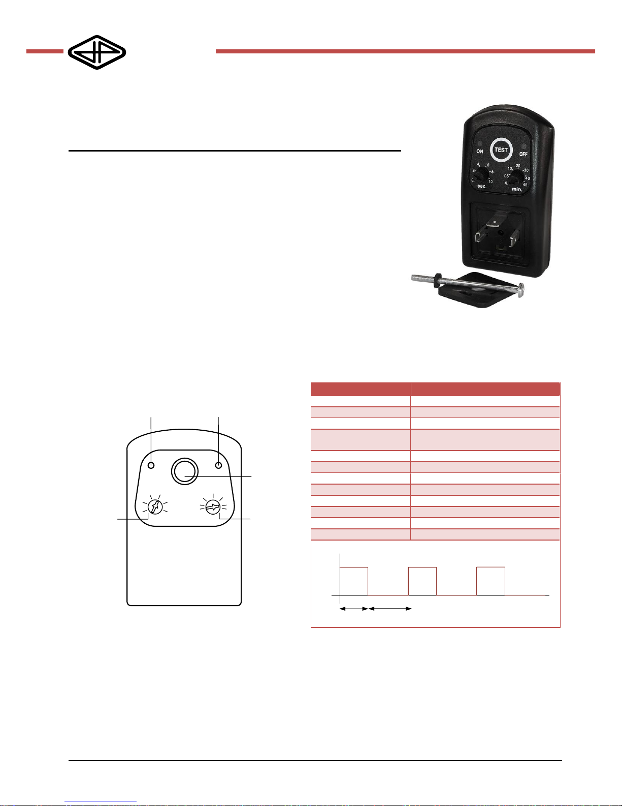
Robust analog timer for electric valves. The switch has a repeating on-off program with an
adjustable pulse (on) of 0 to 10 seconds and an interval time (off) of 0 to 45 minutes. The
program can be stopped by interrupting the power supply. Press the TEST button to restart
the program. The last used program is stored in the memory and is active (in the initial
state) when the power supply is reconnected or the TEST button is pressed. The timer is
compatible with the EN 175301-803 connector (formerly DIN 43650A).
Ideal for
Automatic condensate drains
Sample collections
Lubricating systems
Air dryers
1. PRODUCT SPECIFICATION
ON OFF
TEST
0.5
2
4 6
8
10
0.5
05
10
30
sec.
20
40
45
min.
LED lights in
‘on’ position
LED lights in
‘off’ position
Restart of
program
Set interval
time (off) in
minutes
Set pulse
time (on) in
seconds
Parameter
Value
Voltage
24-230V AC/DC 50Hz/60Hz
Current (continuous)
1A
Current (peak)
10A during 10 ms
Standby power
consumption
4mA max
Operating temperature
-10°C .. +50°C
Lifetime switch
3*10^8 x switching
Time ON
from 0 to 10 seconds (potentiometer)
Time OFF
from 0 to 45 minutes (potentiometer)
Program
repeating ON-OFF
Indicator
Red LED's
Connector
EN 175301-803 (formerly DIN 43650A)
IP-rating
IP65-EN 60529
T
ON
T
OFF
pulse interval
Page 2
JP FLUID CONTROL
MANUAL-SMD-720-EN v1.2 www.jpfluidcontrol.com 2
SMD-720
ANALOG TIMER
2. SAFETY INSTRUCTIONS
► This product is not a safety device and may not be
used as such.
► Damage caused by improper use, falling, improper
operating conditions or others, can cause that the
solenoid valve is not functioning properly. Therefore,
the product should not be used in applications
where a malfunction can cause danger or
damage.
► Correct transport, proper storage and installation,
and proper use and maintenance, are essential for
reliable and error-free operation.
► Check the compatibility of the medium used,
temperature and other operating conditions with
the materials and specifications of the product. It is
the responsibility of the user to select the right
product for the application.
► Never exceed the limits for current, voltage or
frequency as indicated on the product and/or in
the technical documentation.
► It is not allowed to change the construction of this
device.
► Beware of electric shock when working with
electrical equipment. The product only meets the
protection class IP-65 if all seals, connectors and
cables are properly connected.
3. INSTALLATION AND
MAINTENANCE
3.1. Safety instructions before starting
► It is recommended to install the product in a dry
and ventilated environment. In moist environments,
make sure that no moisture can penetrate the coil
or device. Install the device in a safe way to avoid
electric shock, burning, or other injuries. Make sure
the device is not in contact with or in the vicinity of
flammable materials.
► Operations may only be performed when the
system is not pressurized, electrically disconnected
and cooled down.
► Turn off the power supply before performing any
work on the device to prevent the risk of electrical
shock and to prevent activation of the device.
Never connect the power supply, until the
installation is completed and the opening or closing
of the valve is safe.
► The product is only safe when properly installed and
operated by qualified persons. Please read the
safety instructions and technical documentation
carefully before installation, use or servicing.
► Ensure a controlled commissioning after installation
or maintenance.
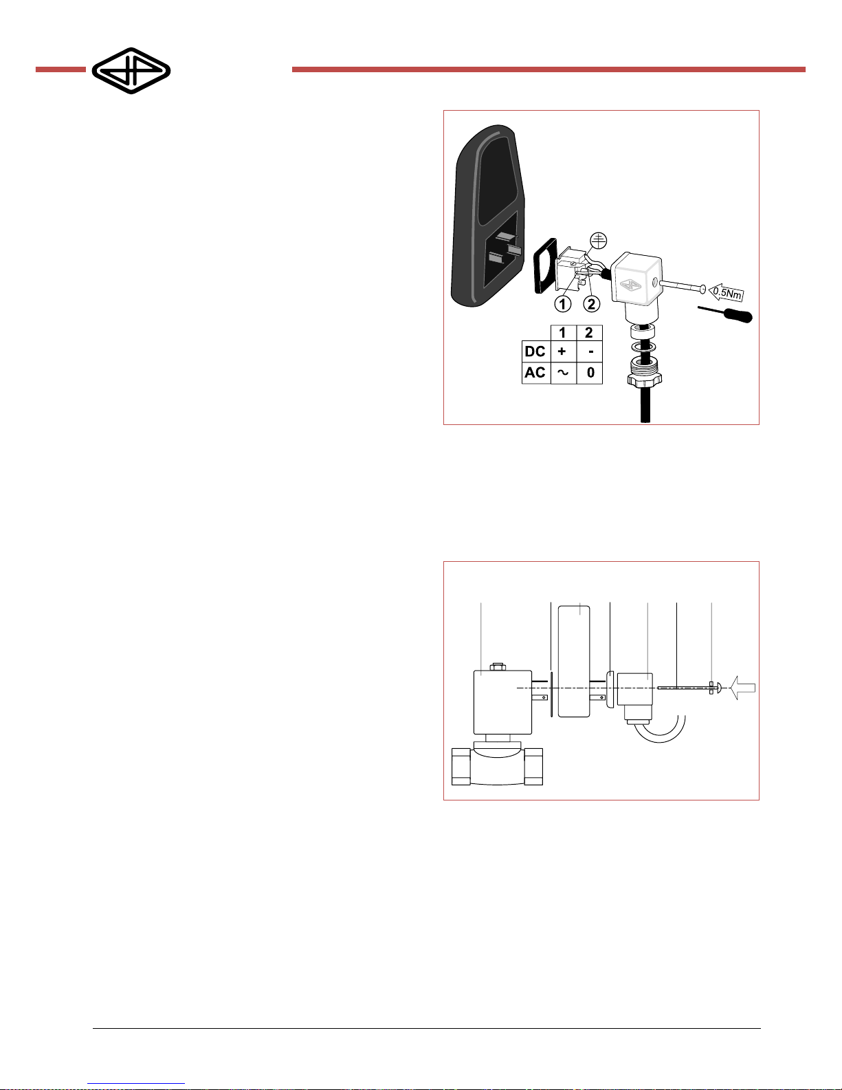
3.2. Electrical connection
► Connect terminal (1) to the positive pole (DC) or the
phase wire (AC). Terminal (2) must be connected to the
negative pole (DC) or neutral wire (AC). Always connect
the ground. In the following drawing the correct wiring is
shown.
3.3. Installation of the timer
► Install the timer between the solenoid valve and the
connector as shown in the diagram below. It is important
that all parts are clean and dry. Ensure that the rubber seals
are well positioned to protect the construction against
moisture. Tighten the screw until the rubbers seal properly,
but do not exceed 0.5Nm.
Solenoid Valve
Rubber
Seal Timer
Rubber
Seal Connector Screw
Rubber
gasket
Page 3
JP FLUID CONTROL
MANUAL-SMD-720-EN v1.2 www.jpfluidcontrol.com 3
SMD-720
ANALOG TIMER
4. SETUP PROGRAM
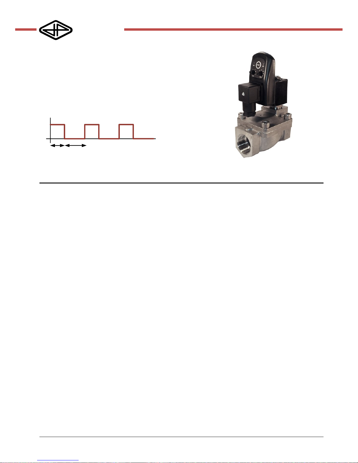
The timer has a repeating ON-OFF program. The program
may be interrupted by terminating the power supply. The
program can be restarted by pressing the TEST button or
interrupting the power supply and connecting again. Set
the two rotary knobs by hand or with a small screwdriver to
the desired position. The left knob (ON period) has an
indication in seconds, the right knob (OFF-period) has a
minute indication.
T
ON
T
OFF
Sample application
This manual can be downloaded from www.jpfluidcontrol.com Modifications reserved © JP Fluid Control
This document has been prepared with great care. JP Fluid control assumes no responsibility for any errors that may appear in this document. No rights can be
derived from this document
 Loading...