

Page 1
1
Page 2
2
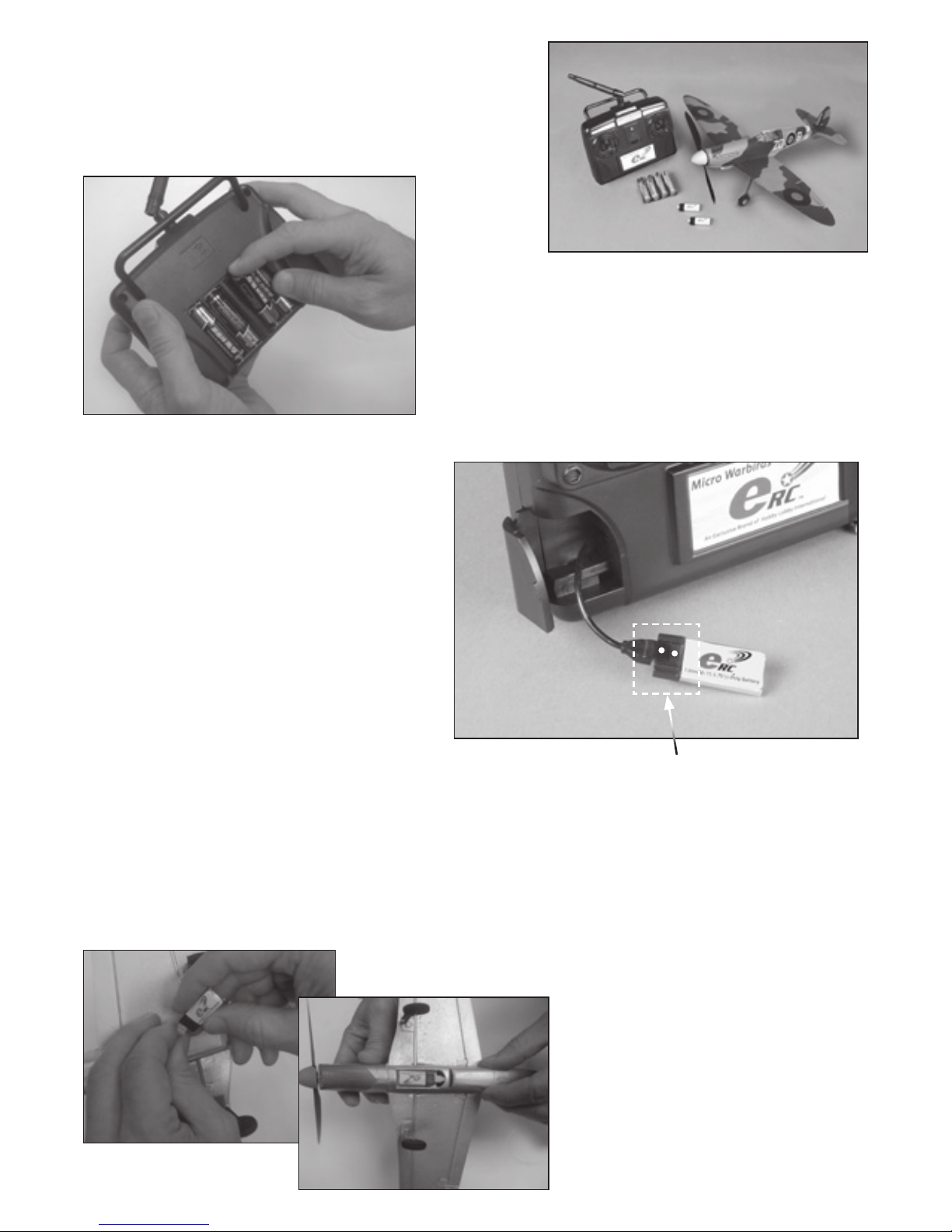
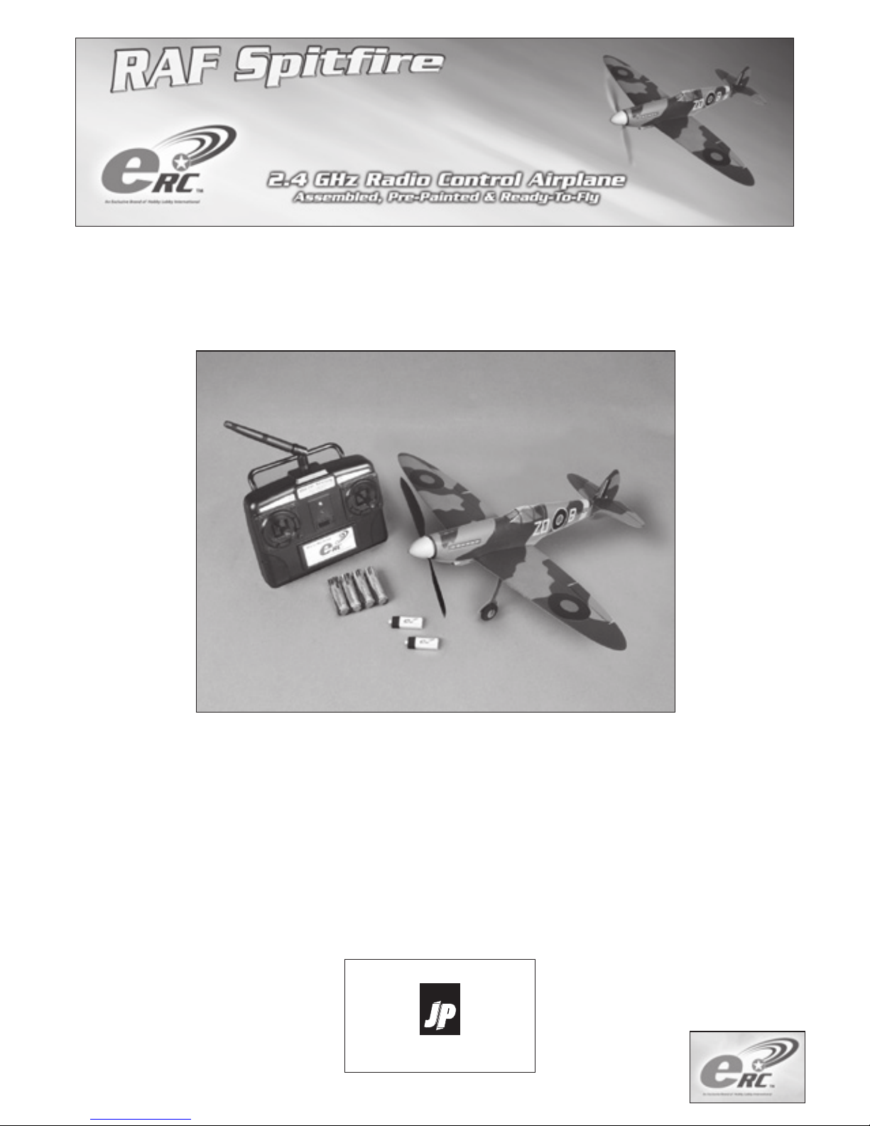
Items Included With Your Model:
Transmitter
AA batteries (4)
Assembled aircraft
Li-Po battery (2)
Install the Transmitter Batteries
Open the rear cover of the transmitter.
Insert the four AA batteries noting the
polarity of the batteries molded into
the transmitter case. Replace the
cover on the transmitter.
Items Included With Your Model:
Transmitter
AA batteries (4)
Assembled aircraft
Li-Po battery (2)
Charging the Flight Battery
Open the door on the transmitter to access
the charger lead. Connect the lead to the
ight battery.
The transmitter can be in either the ON
or OFF position while charging a battery.
Connect the battery to the charge lead from
the transmitter.
If the battery is charging correctly, a yellow
light on the transmitter face will light. When
charging is complete, the yellow light will
go off.
Transmitter Battery Check
When charging with the power switch in the
ON switch position, the signal that the AA
transmitter batteries need to be replaced
will be an audible beep. When charging
with the power switch in the OFF position
the yellow light will become dim when the
AA transmitter batteries are running low.
Note: If you are ying your model while the
transmitter battery power becomes low,
stop ying immediately and replace the
batteries in the transmitter.
Install the Transmitter Batteries
Open the rear cover of the transmitter.
Insert the four AA batteries noting the
polarity of the batteries molded into
the transmitter case. Replace the
cover on the transmitter.
Install the Flight Battery
Once the ight battery has charged,
insert the battery in the fuselage as
shown. The yellow dot on the battery
pack will face to the yellow dot in the
battery compartment in the fuselage.
Make sure the connector on the battery
is aligned properly to the plug in the
fuselage. Take care not to force the
battery in the fuselage. Use only the
supplied battery or ERC replacement
part. Other batteries may damage
the radio system.
Make sure that the coloured dots are lined up on the
battery and charge lead. Plugging the battery in the
wrong way round may damage the pins on the battery.
and is not covered by the warranty.
Page 3
3
Binding the Model
Your model is shipped ready to y. If you nd the controls are
not responding to the transmitter, it may be necessary to bind
the radio system. Use the following to bind the radio system.
1. Turn on transmitter
2. Install the ight battery in airplane (If the transmitter and
receiver are not communicating)
3. Momentarily depress the 2 trim buttons on the throttle
stick Note: Throttle is on the right for Mode 1 and left for
Mode 2.
Note: You do not need to hold them down
4. The airplane will indicate that it is bound by movement of
the aileron and elevator controls
5. Check that the control surfaces are moving in the correct
direction
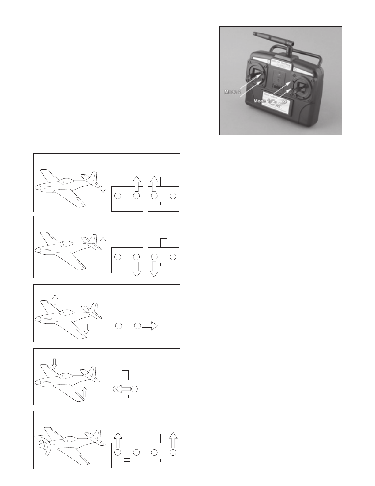
Control Throw
Make sure that the controls for your model operate
correctly.
Elevator Control
Moving the right stick to the top of the transmitter
will make the elevator move down. In the air, this
will cause the plane to dive. Moving the stick toward
the bottom of the transmitter will make the elevator
go up. In ight this will make the model climb.
Aileron Control
Moving it to the right will make the left aileron go
down and the right aileron go up. In ight this will
make the model turn to the right. Moving the stick to
the left will make the left aileron go up and the right
aileron to go down. In ight this will make the model
turn to the left.
Throttle Control
Moving the left stick to the top of the transmitter
will operate the motor. The throttle is proportional,
so as you move the throttle stick up, the speed of
the motor will increase, which increases the ying
speed of the model. We recommend ying at 1/2
to 2/3 throttle for your rst ight to learn the ying
characteristics of your model.
Note: Your radio does have a 4
th
channel for rudder
operation, but is not a function designed into this
particular model. This function would be located on
the same stick as the throttle.
Down Elevator
Mode 2 Mode 1
Up Elevator
Mode 2 Mode 1
Left Aileron
Mode 2 and Mode 1
Right Aileron
Mode 2 and Mode 1
Throttle
Mode 2 Mode 1
Page 4
4
Flying Your Model
Your model has been designed for the intermediate model yer who is
familiar with the use of a four-channel radio system. It is available in
Mode 1 and Mode 2. Always perform a range and ight check to make
sure all controls are operating properly before ying your model.
Range check:
Connect the Li-Poly battery to the aircraft, before turning on the TX
press CH3-, keep the button pressed down and turn on the transmitter.
You will hear 5 consecutive tones, you are now in range check mode.
10 metres distance from the model in range check mode is equivalent to
around 100 metres range in normanl ying mode. Move the transmitter
sticks to ensure all channels are working. To return to normal ying
mode turn off the transmitter and turn it back on again, you will hear 3
beeps to conrm you are back in normal ying mode.
Flight check:
Point the model into the wind. Advance the throttle to 2/3 power. Gently
“push” the model forward with the nose up slightly. You should not need
to throw the model to get it ying. Use small amounts of control throw
until the model has fully reached ying speed to avoid stalling.
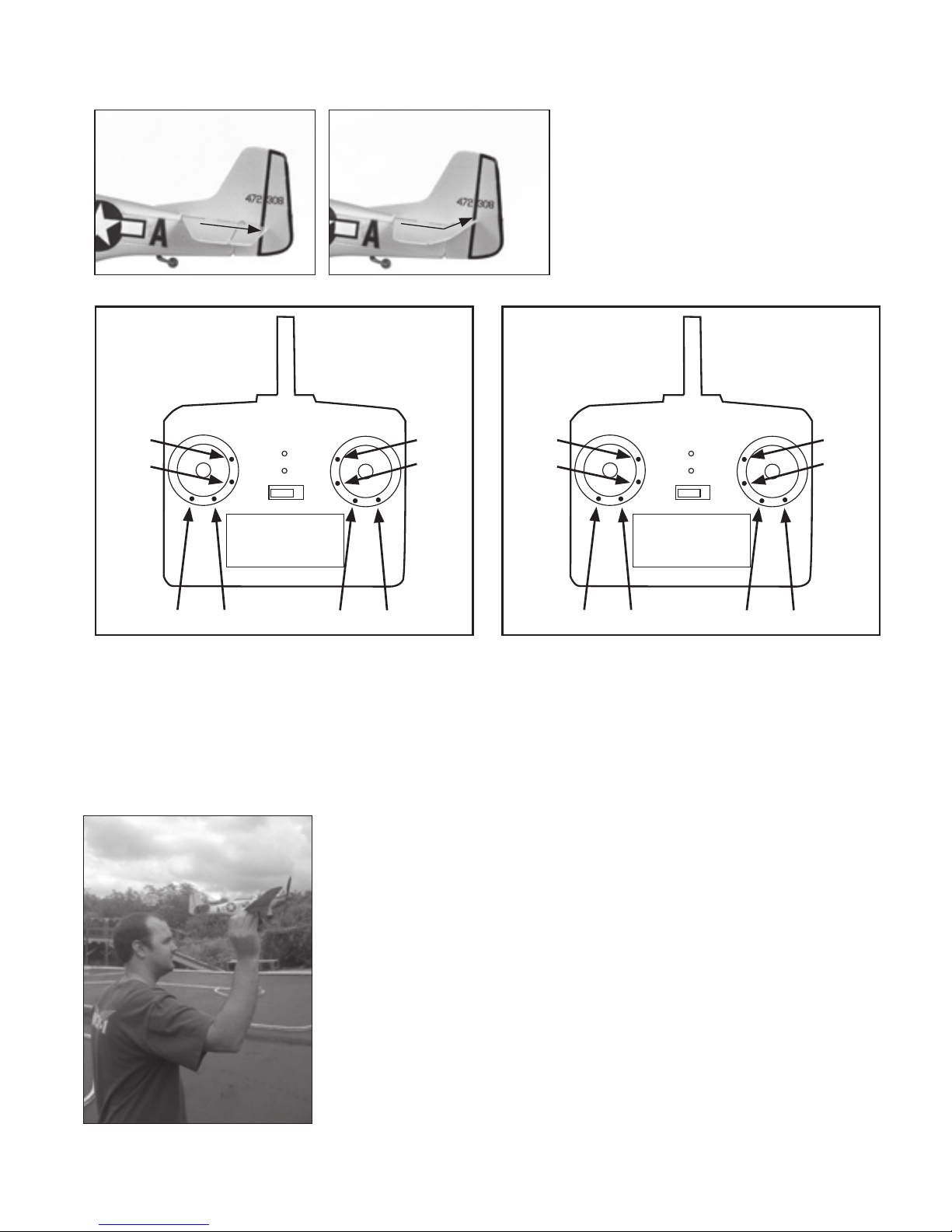
Setting the trim before ight
It may be neccessary to ne trim your model before ight, with all transmitter sticks in neutral all control
surfaces should be at neutral position.
DIGITAL TRIMS:
CH2: Elevator trim buttons
(+ for up and - for down)
CH3: Throttle trim buttons
(+ for increase and - for decrease)
CH4: Aileron trim buttons
(+ for right and - for left)
Ch1 -
Ch1 + Ch4 - Ch4 +
Ch3 -
Ch3 +
Ch2 -
Ch2 +
Mode 2
Ch1 -
Ch1 + Ch4 - Ch4 +
Ch2 -
Ch2 +
Ch3 -
Ch3 +
Mode 1
Servo reverse
Servo directions are factory set and should move in the correct direction. To reverse servo direction
follow this procedure:
Ch2 Elevator servo reverse: Press Ch1+ and Ch2+ or - simultaneously
Ch4 Aileron servo reverse: Press Ch1+ and Ch4+ or - simultaneously
Page 5
5
Trimming the Model in ight
If you nd that your model does not y
straight, it may be necessary to adjust
the trims for straight and level ight.
Trimming is best done when ying at 1/2
to 2/3 power.
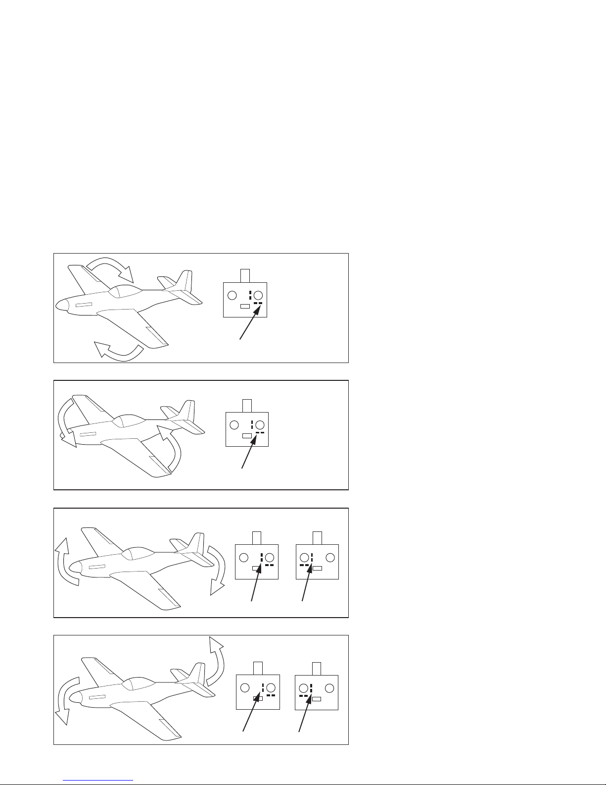
Aileron Trim
If the model appears to turn slightly to
the right or left, it may be required to
adjust the aileron trim. If the model is
turning to the left, press the right aileron
trim until the model ies level. If it is
turning to the right, press the left aileron
trim. You should only use one or two
presses at a time so the model is not
over-trimmed and begins turning the
opposite direction.
Elevator Trim
If the model is climbing or diving in
ight, it may be necessary to adjust the
elevator trim. If the model is climbing,
you will need to press the down elevator
trim. If the model is diving, it will require
that you press the up elevator trim. As
with the aileron, only press the trim once
or twice until the model ies level to
avoid over-trimming.
NOTE: If you reach the end point of the
trim you will hear a continuous beep.
Model rolls left, add right trim
Mode 1 and Mode 2
Model rolls right, add left trim
Mode 1 and Mode 2
Mode 1
Model dives, add up trim
Mode 2
Model climbs, add down trim
Mode 2
Mode 1
Flying Area
You can y your model indoors in an area
the size of a small gymnasium, or outdoors
in a similar sized area or larger. Make sure to
choose an area that is clear of buildings, trees,
power lines or other obstacles that your aircraft
could collide with. Always y your model away
from crowds or spectators to avoid personal
injury.
General Flying Precautions
Always make it a point to practice good ying
techniques. Choose an area large enough that you can
safely maneuver your model. Always y your model in
winds of 3 MPH or less. Avoid ying into the sun.
Page 6
6
Spare parts
The product team at J Perkins hopes that you enjoy your new Micro Series Warbird. Whether ying in
your back garden or displaying on the included stand we think that the Spitre is a model that you’ll be
proud to show off to your friends and ying buddies. If you ever need replacement parts, please refer to
your local model shop. And don’t forget to visit our website regularly at www.jperkinsdistribution.co.uk so
you won’t miss our future new Micro Series releases!
Part # Description
4499350 MD4 Transmitter: Micro Warbirds
4499352 Receiver/Servo Board: Micro Spitre
4499355 130 mAh Li-Po Battery: Micro Collection
4499400 Motor and Gear Box: Micro Spitre
4499401 Painted Fuselage: Micro Spitre
4499402 Painted Wing: Micro Spitre
4499403 Replacement Canopy: Micro Spitre
4499404 Underwing Belly Pan: Micro Spitre
4499405 Tail Set: Micro Spitre
4499406 Propeller Shaft: Micro Spitre
4499407 Prop/Spinner: Micro Spitre
4499408 Complete Landing Gear Set: Micro Spitre
4499409 Decal Sheet: Micro Spitre
4499410 Display Stand: Micro Spitre
Warranty Information
For a period of one year from time of purchase, J. Perkins Distribution Ltd will repair or replace, at it’s
discretion, any items showing manufacturing or assembly defects that has been found faulty by our
service department. This does not affect your statutory rights.
J Perkins Distribution Ltd does not accept any liability for any injury, damage or consequential damage
arising as a result of failure to observe the procedures and precautions outlined in this manual. J
Perkins Distribution Ltd does not accept any liability that may arise from any misuse or modication of
this equipment, Please note that, whilst every effort is made to ensure the accuracy of instructions and
materials included with this product, mistakes can occur and neither J. Perkins Distribution Ltd nor it’s
distributors will be held liable for any loss or damage arising from the use of this system or for any loss
or damage arising from omissions or inaccuracies in the associated instructions, references, web sites or
materials included or referred to with this product.
We reserve the right to modify the design of this product, the box contents and manual without prior
notication. E&OE
© 2009 J Perkins Distribution Ltd. All rights reserved.
web: www.jperkinsdistribution.co.uk
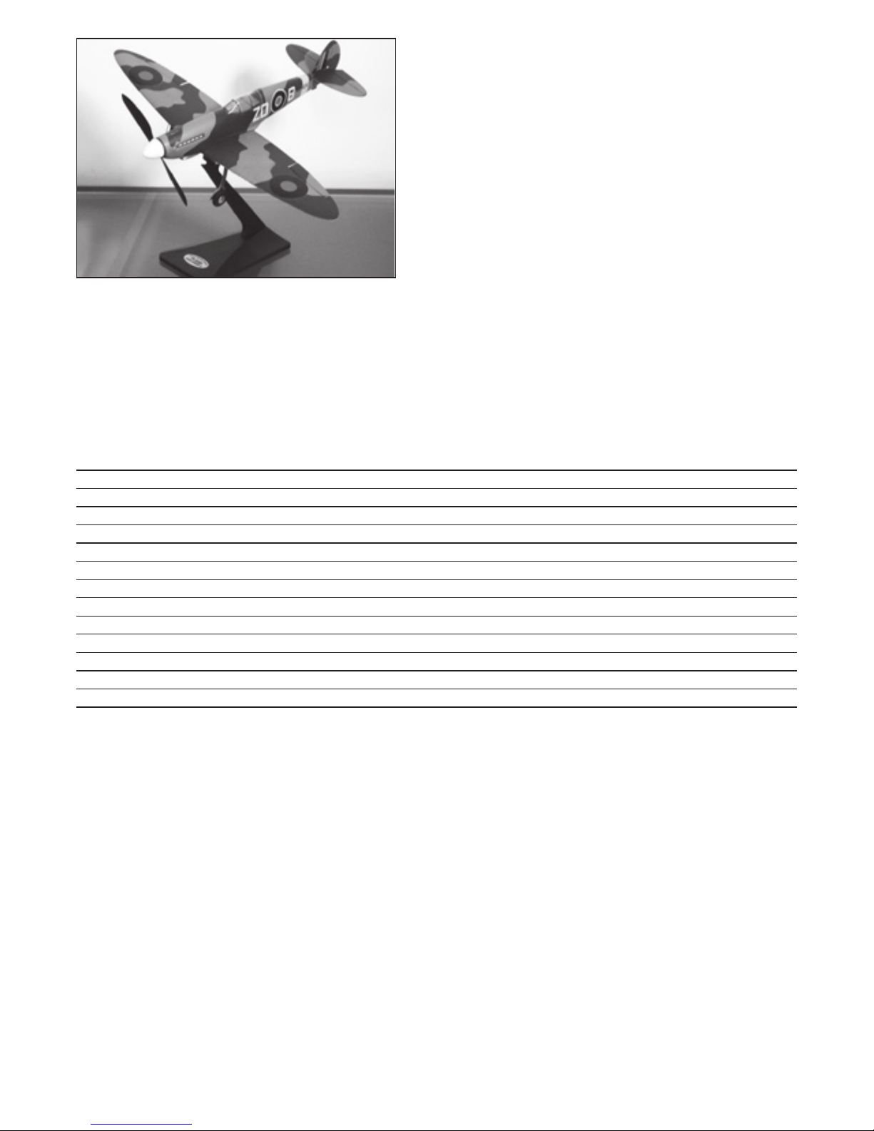
Display your Model
When not ying your model, you can
use the included stand to display your
model. Simply place the model on the
stand and keep it nearby for when you
want to go out and enjoy some ight
time. Always remember to remove the
battery before placing your model on
the stand
Page 7

7
Safety Instructions for Charging and Using Li-Poly Batteries
• Do not put the battery on, or near anything, that can catch re when charging.
• Always charge the battery on a non-ammable base i.e. a metal tray.
• Do not disassemble the battery.
• Do not short-circuit the battery.
• Do not use, or leave, the battery nearby a re, stove or heated place.
• Do not immerse the battery in water or seawater, do not get it wet.
• Do not charge the battery near a re or under the blazing sunlight.
• Do not drive a nail into the battery, strike it with hammer or apply excessive weight to the battery.
• Do not impact or throw the battery.
Safety Precautions
1. Please do not change any part of the plane without checking with J Perkins (Dist) Ltd. You will be
responsible for any damages caused by these changes.
2. Your ying area should be wide-open and free of obstacles. Never y near highways, railways,
airports, power lines or in residential areas.
3. To avoid personal injury, never y your model near or facing people, or throw the plane in their
direction.
4. Do not y your model outdoors in winds over 3MPH.
5. Never dispose of batteries or parts of your model in a re as it could lead to an explosion and
personal injury.
General Safety Statements
1. This aircraft is not a toy. It has been designed for the experienced modeller and pilot. You are
responsible not to cause damage to other’s personal property or cause personal injury.
3. J Perkins (Dist) Ltd and our dealers are not responsible for any economic or law liability for any
improper usage or operation of this model.
4. This model is designed for use by modelers age 14 and over. This model is not recommended for
unsupervised modellers under 16 years of age.
5. Never use the model or associated electronics in damp or rainy conditions.
6. This model is made from EPS and Polystyrene, which can be damaged by excessive heat. Keep your
model away from excessive heat or out of direct sunlight for extended time periods or it can become
warped and affect the ight performance of the model.
8. Never leave the battery connected while the model is unattended. Accidental operation can occur and
cause personal injury.
9. Before operating the model, make sure to turn on the radio system and check the functions before
beginning ight.
10. Always make sure the throttle at the transmitter has been moved to the low or off position before
connecting the motor battery.
EU regulations
J Perkins Distribution Ltd declares that this remote control system is in compliance with the essential
requirements and other relevant provisions of Directive 1999/5/EC on Radio equipment and
Telecommunications Terminal Equipment. A copy of the declaration(s) of conformity can be obtained
from J Perkins Distribution Ltd, Ashford rd, Lenham, Kent. UK ME17 2DL. This system complies with the
EU directive on Waste Electrical and Electronic Equipment. Do not dispose of this product in household
waste. At the end of the products’ life, dispose of it at a designated collection point for the recycling of
waste electrical and electronic equipment.
Please contact your supplier for any advice required on disposal.
Page 8
8
Have Fun!
We hope that you have many pleasant ights with your
RAF Spitre Micro!
J Perkins Distribution, Lenham, UK
www.jperkinsdistribution.co.uk
V3.10
 Loading...