

Page 1
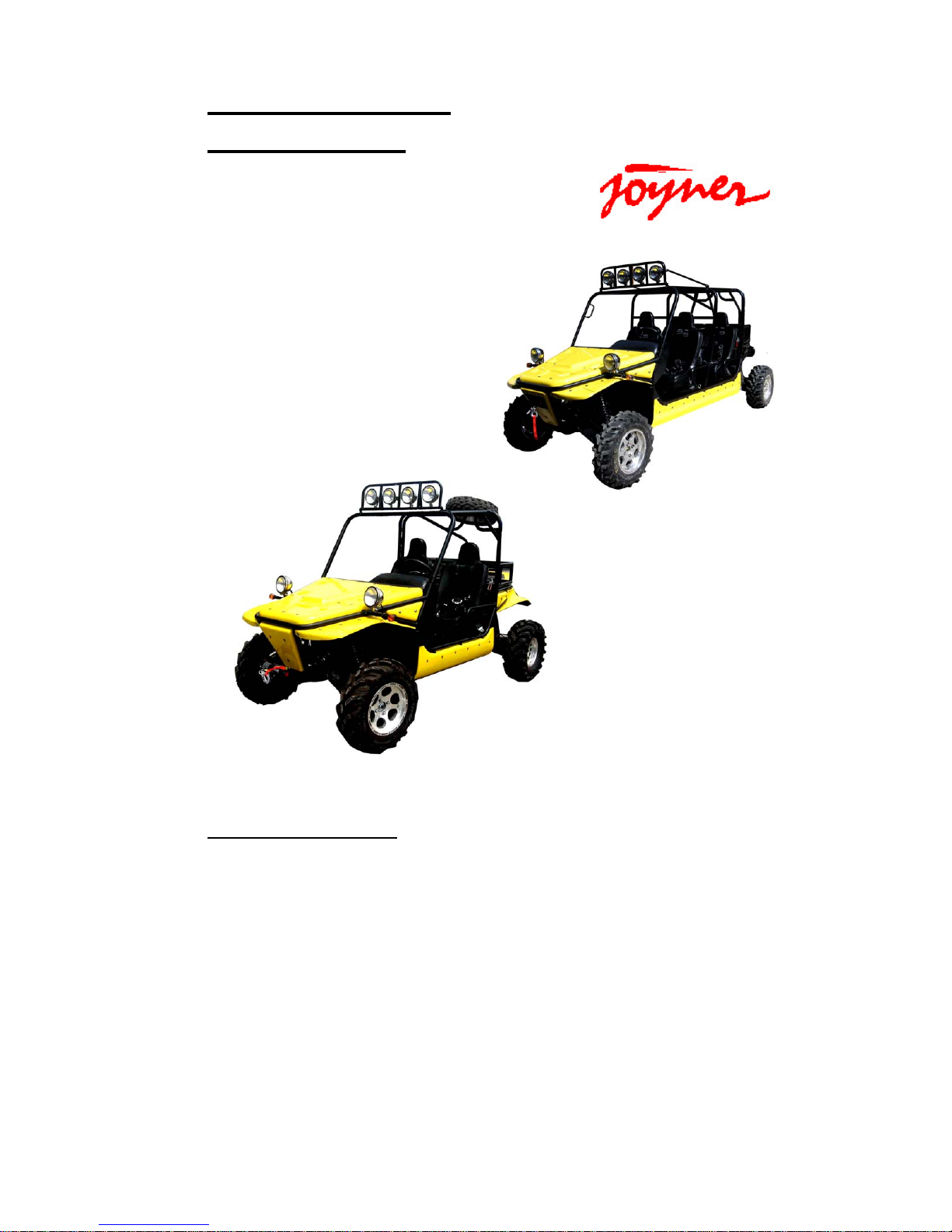
1
Owner’s Manual
Parts manual
READ THIS MANUAL CAREFULLY
IT CONTAINS IMPORTANT SAFETY INFORMATION.
MINIMUM
RECOMMENDED
OPERA TOR AGE:
FOR OFF-ROAD USE ONLY
This vehicle is designed and manufactured for off-road use only.
USA only;
It does not confirm to federal motor vehicle safety standards, and operation on public streets,
roads, or highways is illegal.
16
TROOPER-T2,T4
Page 2

2
INTRODUCTION
Thank you for choosing JOYNER TROOPER. It represents the result of
many years of JOYNER experience in the production of utility vehicles. With
the purchase of this JOYNER, you can now appreciate the high degree of
craftsmanship and reliability that have made JOYNER a leader in this
field .This manual will provide you with a good basic understanding of the
features and operation of this vehicle. It also includes basic maintenance
and inspection procedures. If you have any questions regarding the
operation or maintenance of your vehicle, please consult a JOYNER dealer.
Please read this manual carefully before operating this vehicle. Do not
attempt to operate this vehicle until you have attained adequate knowledge
of its controls and operating features. Regular inspections and careful
maintenance, along with good operating techniques, will help ensure that
you safely enjoy the capabilities and reliability of this vehicle.
Page 3

3
CONTENTS
Owner’s manual ............................................................................................................................................ 7
Warranty policy ....................................................................................................................................... 7
Parts order form, warranty claim form ................................................................................................ 11
Service record form .............................................................................................................................. 12
Preventative maintenance and service log ........................................................................................ 13
Location of warning labels and specification labels ......................................................................... 18
Safety information ................................................................................................................................. 22
Are you ready to drive? ........................................................................................................................ 24
Protective apparel ............................................................................................................................ 24
Helmets and ayes protection .......................................................................................................... 24
Drive training ..................................................................................................................................... 25
Age recommendation ...................................................................................................................... 25
No alcohol or drugs .......................................................................................................................... 25
Is your vehicle ready to drive? ............................................................................................................ 26
Pre-drive Inspection .............................................................................................................................. 26
Operation instructionMain switch ....................................................................................................... 28
Battery switch ................................................................................................................................... 28
Gauges .............................................................................................................................................. 29
Switches ............................................................................................................................................ 29
Steering wheel .................................................................................................................................. 31
Pedal .................................................................................................................................................. 32
Parking brake lever .......................................................................................................................... 32
Drive select lever .............................................................................................................................. 33
Differential control handle ............................................................................................................... 33
Fuel tank ............................................................................................................................................ 34
Seats and safety belts ..................................................................................................................... 34
Safari bed .......................................................................................................................................... 36
Start engine ....................................................................................................................................... 36
Stop engine ....................................................................................................................................... 37
Passenger ......................................................................................................................................... 37
Break-in ............................................................................................................................................. 37
Starting and operating instructions ................................................................................................ 38
Specifications ........................................................................................................................................ 39
Maintenance and adjustment ...................................................................................................................... 42
Air Cleaner ............................................................................................................................................. 42
Engine Lubrication ................................................................................................................................ 42
Transmission lubrication ...................................................................................................................... 43
Differential lubrication .......................................................................................................................... 44
Engine Coolant ...................................................................................................................................... 44
Idle Speed .............................................................................................................................................. 46
Spark plug inspection ........................................................................................................................... 46
Page 4

4
Wedge belt figure .................................................................................................................................. 48
Shift cable adjustment .......................................................................................................................... 48
Parking brake cable adjustment .......................................................................................................... 49
Steering lubrication............................................................................................................................... 50
Throttle cable adjustment .................................................................................................................... 51
Differential lock cable adjustment ....................................................................................................... 51
Spot light adjustment............................................................................................................................ 52
Oil filter change ..................................................................................................................................... 53
Fuel pressure adjustment .................................................................................................................... 53
Front Wheel Replacement .................................................................................................................... 54
Rear Wheel Replacement ..................................................................................................................... 54
Clutch replacement ............................................................................................................................... 55
Front Wheel Alignment ......................................................................................................................... 58
Fuse and relay ....................................................................................................................................... 58
Bulb replacement .................................................................................................................................. 60
Shock adjustment ................................................................................................................................. 62
Chassis wiring diagram ........................................................................................................................ 64
Engine wiring diagram .......................................................................................................................... 65
Engine disassembly, installation and repair ...................................................................................... 66
Timing Belt ........................................................................................................................................ 66
Camshaft ........................................................................................................................................... 73
Cylinder head .................................................................................................................................... 82
Water pump ....................................................................................................................................... 89
Oil pump ............................................................................................................................................ 90
Crankshaft connecting rod mechanism ........................................................................................ 98
Electric injection system ................................................................................................................ 109
PARTS MANUAL ...................................................................................................................................... 149
1. ENGINE ............................................................................................................................... .............. 149
1. COOLING SYSTEM .................................................................................................................. 149
2. CYLINDER BLOCK ................................................................................................................... 150
3. CRANKSHAFT ........................................................................................................................... 151
4. EXHAUST MANIFOLD ............................................................................................................. 152
5. INTAKE SYSTEM ...................................................................................................................... 153
5. INTAKE SYSTEM ...................................................................................................................... 154
6. LUBRICATING DEVICE ........................................................................................................... 155
7. CYLINDER HEAD ..................................................................................................................... 156
7. CYLINDER HEAD ..................................................................................................................... 157
8. COVER-VALVE CHAMBER ..................................................................................................... 158
9. OIL PAN ...................................................................................................................................... 159
10. VALVE MECHANISM .............................................................................................................. 160
10. VALVE MECHANISM .............................................................................................................. 161
10. VALVE MECHANISM .............................................................................................................. 162
11. IGNITION DEVICE .................................................................................................................. 163
Page 5

5
12. PISTON AND CONNECTING ROD DEVICE ...................................................................... 164
13. OTHER ACCESSORY 1......................................................................................................... 165
14. OTHER ACCESSORY 2......................................................................................................... 166
2.5T07D1 TRANSMISSION .................................................................................................................. 167
1 CASE&ACCESSORY ................................................................................................................ 167
1 CASE&ACCESSORY ................................................................................................................ 168
2 COUNTERSHAFT ...................................................................................................................... 169
2 COUNTERSHAFT ...................................................................................................................... 170
3 INPUT SHAFT ASSY ................................................................................................................. 171
3 INPUT SHAFT ASSY ................................................................................................................. 172
3 INPUT SHAFT ASSY ................................................................................................................. 173
4 SHIFT FORK&SHIFT-FORK SHAFT ....................................................................................... 174
4 SHIFT FORK&SHIFT-FORK SHAFT .................................................................................... 175
5 SHIFT CONTROL MACHINSM ................................................................................................ 176
6 DRIVEN GEAR ASSY ................................................................................................................ 178
3. CHASSIS .......................................................................................................................................... 179
1.Frame assembly ......................................................................................................................... 179
2.Engine mount assy ..................................................................................................................... 181
3.Muffler ........................................................................................................................................... 182
4.Gear-shift mechanism ................................................................................................................ 183
4.Gear-shift mechanism ................................................................................................................ 184
5.Steering assembly ...................................................................................................................... 185
5.Steering assembly ...................................................................................................................... 186
5. Steering assembly ..................................................................................................................... 187
6. Throttle, parking brake, brake .................................................................................................. 188
6. Throttle, parking brake, brake .................................................................................................. 190
6. Brake (TR1100.07.01.01.00B, TR1100.07.01.01.
00B-T4).................................................. 192
6. Parking ........................................................................................................................................ 193
6. Clutch (TR1100.07.04.01.00, TR11
00.07.04.01.00-T4) ...................................................... 194
7. Front and rear suspension assembly ..................................................................................... 195
7.Front and rear suspension assembly ...................................................................................... 196
8.Driven system .............................................................................................................................. 197
8. Driven system ............................................................................................................................ 199
9. Front/Rear differential locking .................................................................................................. 201
10.Fuel tank and gasoline pump ................................................................................................. 202
10.Fuel tank and gasoline pump ................................................................................................. 204
11.Radiator assembly .................................................................................................................... 206
11.Radiator assembly .................................................................................................................... 207
12.Roll bar and Rearview mirror .................................................................................................. 208
12.Roll bar and Rearview mirror .................................................................................................. 209
13. Cargo bed ................................................................................................................................. 212
14. Electrical winch ........................................................................................................................ 213
15. Plastic parts .............................................................................................................................. 214
15. Plastic parts .............................................................................................................................. 215
Page 6

6
16. Seats and safety belts ............................................................................................................ 218
17.Other parts ................................................................................................................................. 220
17.Other parts ................................................................................................................................. 221
DEALER PRE-DELIVERY INSPECTION ............................................................................................. 222
Page 7

7
Owner’s manual
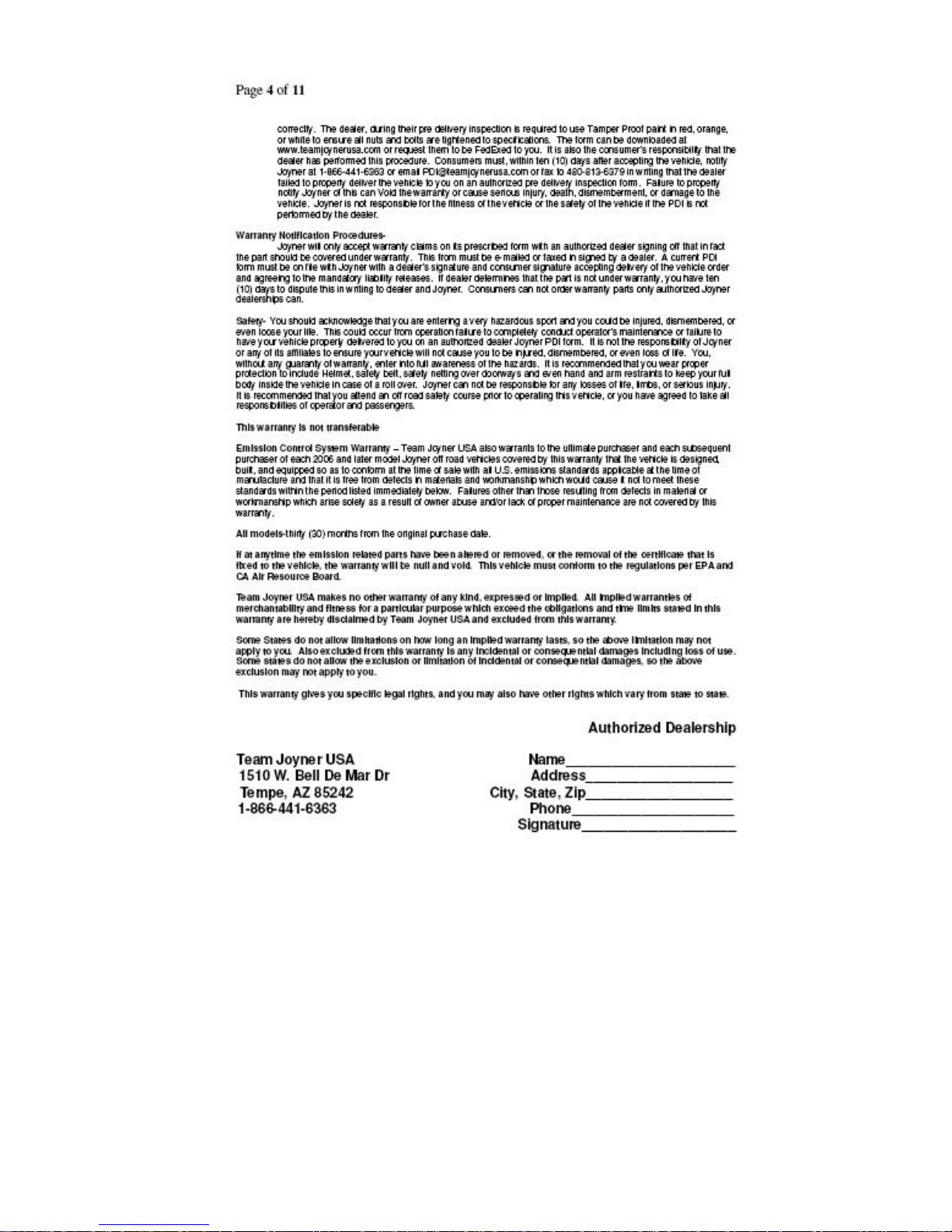
Warranty policy
Page 8

8
Page 9

9
Page 10
10
Page 11
11
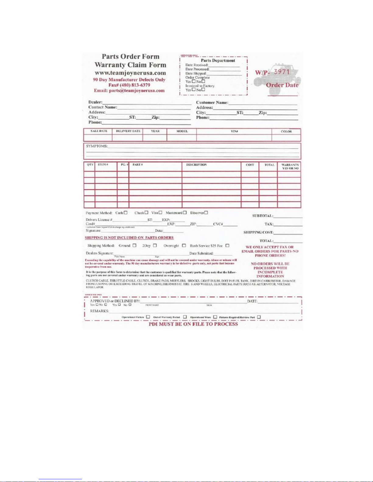
Parts order form, warranty claim form
Page 12

12
Service record form
Page 13
13
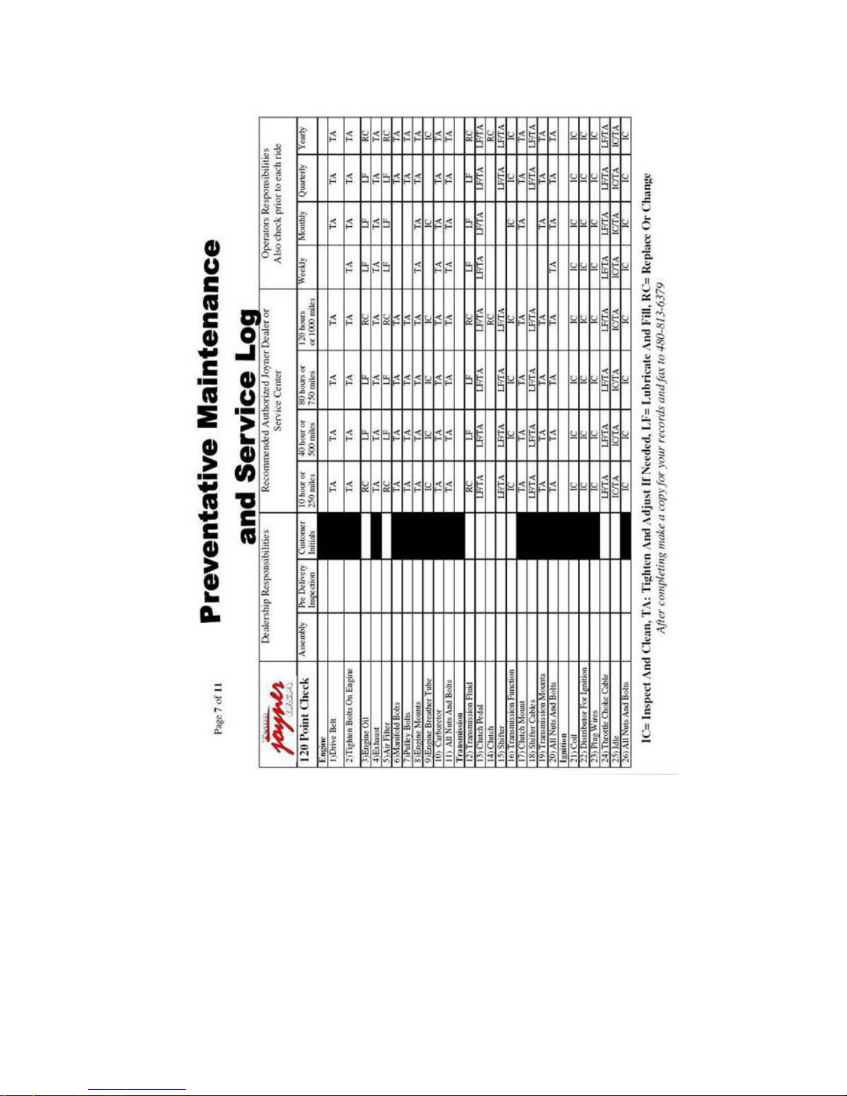
Preventative maintenance and service log
Page 14

14
Page 15

15
Page 16
16
Page 17

17
Page 18
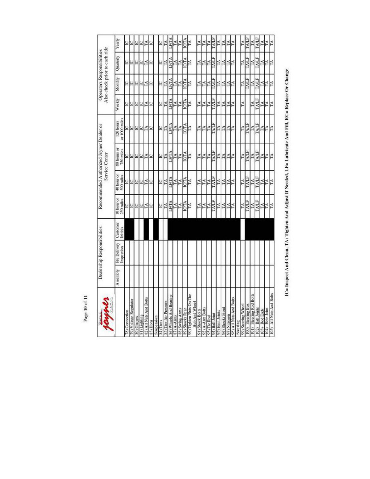
18
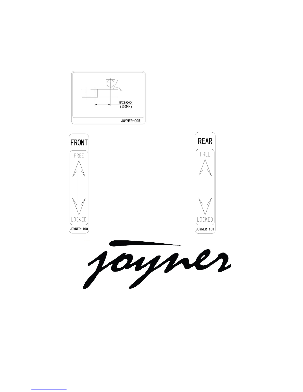
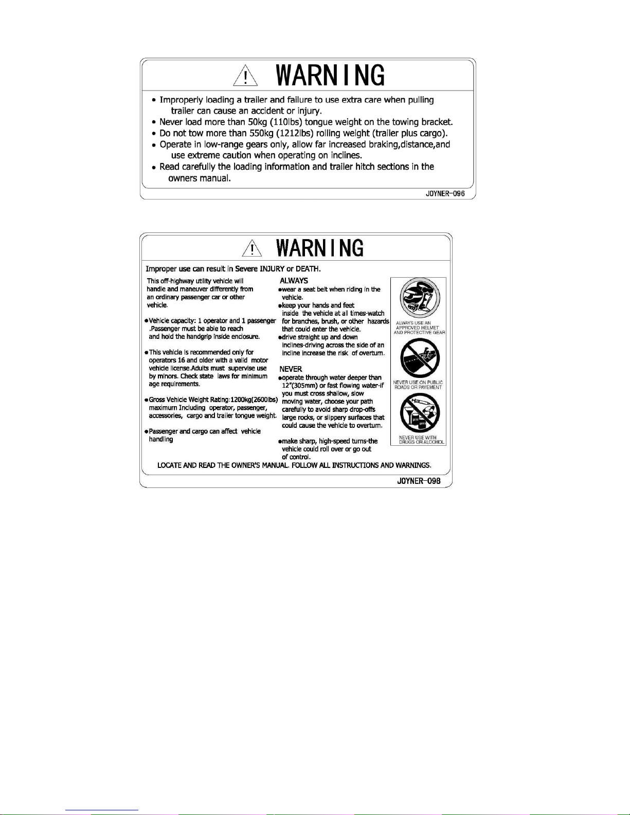
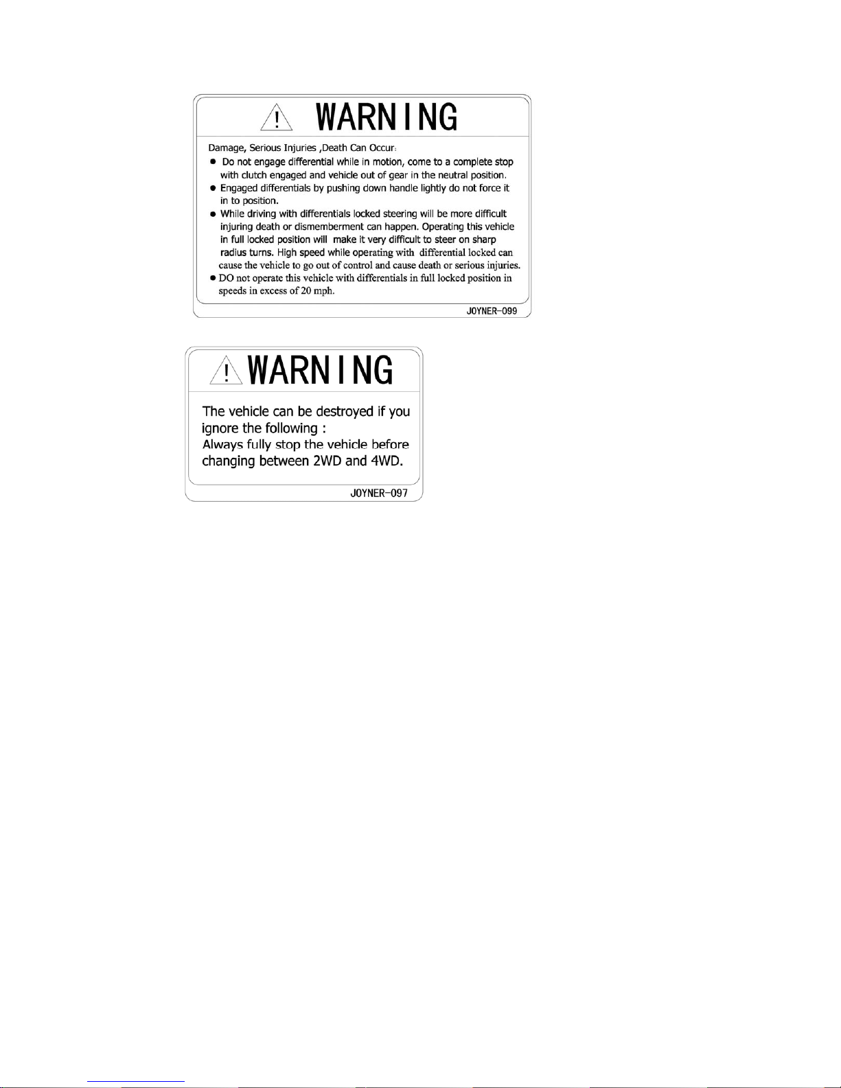
Location of warning labels and specification labels
Read and understand all of the labels on your vehicle. They contain important
information for safe and proper operation of your vehicle.
Never remove any labels from your vehicle. If a label becomes difficult to read or comes
off, a replacement label is available from your Joyner dealer.
Page 19

19
Page 20
20
Page 21
21
Page 22

22
Safety information
THE SAFETY IS FIRST. Severe injury or death can result if you do not follow these
instructions. Read this manual and all labels carefully and follow the operating
procedures described:
1. This vehicle is designed to carry the driver and one passenger. Never carry
passengers in the safari bed.
2. Always be sure the driver and passengers are wearing seat belts.
3. Never give a ride to a passenger who is too small to reach and hold the handgrip on
the enclosure.
4. Always avoid operating the vehicle on any paved surfaces, including sidewalks,
driveways, parking lots, and streets.
5. Never operate this vehicle on any public street, road, or highway, even a dirt or
gravel one.
6. Never operate this vehicle without wearing an approved motorcycle helmet that fits
properly. You should also wear eye protection (goggles or a face shield), gloves,
over-the-ankle boots, long-sleeved shirt or jacket, and long pants.
7. Never consume alcohol or drugs before or while operating this vehicle.
8. Never operate at speeds too fast for your skills or the conditions. Always go at a
speed that is proper for the terrain, visibility, operating conditions, and your experience.
9. Never attempt jumps or other stunts.
10. Always inspect your vehicle each time you use it to be sure it is in safe operating
condition. Always follow the inspection and maintenance procedures and schedules
described in this manual.
11. Always keep both hands, arms, feet, and legs inside the vehicle at all times during
operation. Keep your feet on the floorboard. Never hold onto the enclosure except when
using the handgrip inside the enclosure. Otherwise, your hand could be injured if it is
caught between the enclosure and an obstacle outside the vehicle.
12. Always keep both hands on the steering wheel when driving.
13. Never wrap your thumbs and fingers around the steering wheel. This is particularly
important when driving in rough terrain. The front wheels will move right and left as they
respond to the terrain, and this movement will be felt in the steering wheel. A sudden jolt
could wrench the steering wheel around, and your thumbs or fingers could be injured if
they are in the way of the steering wheel spokes.
14.Always go slowly and be extra careful when operating on unfamiliar terrain. Always
be alert to changing terrain conditions when driving the vehicle.
15. Never operate on excessively rough, slippery, or loose terrain until you have
learned and practiced the skills necessary to control the vehicle on such terrain. Always
be especially cautious on these kinds of terrain.
16. Never turn at excessive speed. Practice turning at slow speeds before attempting
to turn at faster speeds. Do not attempt turns on steep inclines.
17. Never operate the vehicle on hills that are too steep for it or for your abilities. Go
straight up and down hills where possible. Maximum slope angle: 15º .
Page 23

23
18. Never operate on hills that are slippery or ones where you will not be able to see
far enough ahead of you. Never go over the top of a hill at speed if you cannot see what
is on the other side.
19. Always follow proper procedures for going uphill. If you lose momentum and
cannot continue up a hill, back down the hill with the engine in reverse gear. Use engine
braking to help you go slowly. If necessary, use the brakes gradually to help you go
slowly.
20. Always check terrain carefully before going down hills. Go as slowly as possible.
Never go down a hill at high speed.
21. Always check for obstacles before operating in a new area.
22. Never operate the vehicle in fast flowing water or water deeper than the
floorboards on this model. Remember that wet brakes may have reduced stopping ability.
Test your brakes after leaving water. If necessary, apply the brakes lightly while the
vehicle is moving so the friction dries out the lining.
23. Always be sure there are no obstacles or people behind you when you operate in
reverse. When it is safe to proceed in reverse, go slowly. Do not brake abruptly when
carrying loads in the safari bed.
24. Always use the size and type of tires specified in this manual.
25. Always maintain proper tire pressure as described in this manual.
26. Never exceed the stated load capacity. Cargo should be as far forward in the bed
as possible, and distributed evenly from side to side. Be sure cargo is secured so that it
cannot move around during operation. Reduce speed and follow instructions in this
manual for carrying cargo or pulling a trailer. Allow greater distance for braking.
Page 24

24
Are you ready to drive?
Before each drive, you need to make sure you and your TROOPER are both ready to
drive. To help get you prepared, this section discusses how to evaluate your driving
readiness, what items you should check on your TROOPER, and adjustments to make
for your comfort, convenience, and safety.
Before you drive your TROOPER for the first time, we urge you to:
■ Read this owner’s manual and the labels on your TROOPER carefully.
■ Make sure you read and understand all the safety instruction before driving this
vehicle.
■ Know how to operate all the controls.
Before each drive, be sure:
■ You are wearing an approved motorcycle helmet (with chin strap tightened securely),
eye protection, and other protective clothing.
■ You don’t have any alcohol or drugs.
Protective apparel
For your safety, we strongly recommend that you always wear an approved motorcycle
helmet, eye protection, boots, gloves, long pants, and long-sleeved shirt or jacket
whenever you drive.
Although complete protection is not possible, wearing proper gear can reduce the
chance of injury when you drive.
The following suggestions will help you choose the proper driving gear.
Helmets and ayes protection
Your helmet is your most important piece of driving gear because it offers the best
protection against head injuries. A helmet should fit your head comfortably and securely.
An open-face helmet offers some protection, but a full-face helmet offers more.
Regardless of the style, look for a DOT (Department of Transportation) sticker in any
helmet you buy. Always wear a face shield or goggles to protect your eyes and help your
vision.
Operating TROOPER without wearing an approved motorcycle helmet, eye
protection, and protective clothing could increase your chances of head or eye
injury, possibly death in the event of severe accident.
Always wear approved motorcycle helmet that fits properly and wear eye
protection (goggles or face shield), gloves, boots, long-sleeved shirt or jacket and
long pants.
Additional Driving Gear
In addition to a helmet and eye protection, we also recommend:
■ Sturdy off-road motorcycle boots to help protect your feet, ankles, and lower legs.
■ Off-road motorcycle gloves to help protect your hands.
Page 25

25
Drive training
Developing your driving skills is an on-going process. Even if you have driven other
TROOPER, take time to become familiar with how TROOPER works and handles.
Practice driving TROOPER in a safe area to build your skills. Do not drive in rough
terrain until you get accustomed to TROOPER’s controls, and feel comfortable with its
size and weight.
Operating TROOPER without proper instruction could increase your risk of an
accident which could lead to serious injury or death.
Attempt supporting with your hands to the ground when the Off Highway
Recreational vehicles turning over could lead to serious injury or death.
Never support with your hands to ground when the Off Highway Recreational
vehicles will turn over.
Age recommendation
It is strongly recommended that no one under the age of 16 permitted to ride the
TROOPER without adult supervision.
A child driving a TROOPER that is not recommended for his/her age could lose
TROOPER control and result in severe injury or death.
A child under 16 should have adult supervision when operate on TROOPER.
No alcohol or drugs
Alcohol, drugs and TROOPER don’t mix. Even a small amount of alcohol can impair your
ability to operate a TROOPER safely. Likewise, drugs, even if prescribed by a physician,
can be dangerous while operating a TROOPER. Consult your doctor to be sure it is safe
to operate a vehicle after taking medication.
Operating TROOPER after consuming alcohol or drugs can seriously affect your
judgment, cause you to react more slowly, affect your balance and perception, and
could result in serious injury or death.
Never consume alcohol or drugs before or while operating TROOPER.
Page 26

26
Is your vehicle ready to drive?
Before each drive, it is important to inspect your TROOPER and make sure any
problems you find are corrected. A pre-drive inspection is a must, not only for safety, but
because having a breakdown, or even a flat tire, can be a major inconvenience.
If your TROOPER has overturned or has been involved in a collision, do not drive it until
your TROOPER has been inspected by your dealer. There may be damages or other
problems you cannot see.
Improperly maintaining TROOPER or failing to correct a problem before driving
can cause a crash in which you can be seriously hurt or even dead.
Always perform a pre-drive inspection before every drive and correct any
problems.
Pre-drive Inspection
Check the following items before you get on TROOPER:
■ Engine Oil
Check the level and add oil if needed. Check for leaks.
■ Coolant
With the engine cold, check the coolant and add if needed. Check for leaks
■ Fuel
Check the level and add fuel if needed. Also make sure the fuel cap is securely
fastened. Check for leaks.
■ Tires
Use a gauge to check the air pressure. Adjust if needed. Also look for signs of
damages or excessive wear.
■ Nuts & Bolts
Check the wheels to see that the axle nuts are tightened, Use a wrench to make sure
all accessible nuts, bolts, and fasteners are tight.
■ Underbody & Exhaust System
Check for, and remove any dirt, vegetation or other debris that could be fire hazard or
interfere with the proper operation of TROOPER.
■ Air Cleaner
Check the air filter. Replace it if needed.
■ Leaks, Loose Parts
Walk around your TROOPER and look for anything that appears unusual, such as a
leak or loose cable.
Page 27

27
■ Lights
Make sure the headlight, brake light and tail light are working properly.
■ Throttle
Check the free play and adjust if needed. Press the throttle to make sure it moves
smoothly without sticking, and snaps back automatically when it is released.
■ Clutch cable
Check the free play of clutch cable and adjust if needed. Press the clutch cable to make
sure it moves smoothly without sticking, and snaps back automatically when it is
released.
■ Brakes
Press the brake pedal several times, check for proper brake pedal free play. Make sure
there is no brake fluid leakage.
■ Engine Stop
When engine is running, turn the switch key counterclockwise. Make sure engine stops.
■ Steering Wheel
Check that the wheels turn properly as you turn the steering wheel.
■ Cable
Check the cable housing for wear. Check the fittings are tight. Replace or tighten as
needed.
■ Tie rod
Check the tie rod housing for wear. Check the fittings are tight. Replace or tighten as
needed.
Page 28

28
Operation instructionMain switch
Functions of the respective switch positions are as follows:
OFF:
All electrical components are switched off except for the turning signals. The ignition key
can only be removed in the OFF position
ON1:
All electrical circuits are supplied with power, except
the ignition system and fuel system, the headlights and
taillights come on when the light switch is on.
ON 2:
The ignition system and fuel system are supplied with power.
START:
The electric starter is engaged by turning and holding the key in this position. Release
the key when the engine starts.
Do not operate the electric starter continuously for more than 5 seconds, or starter
damage could occur. Wait at least 5 seconds between each operation of the electric
starter to let it cool.
Do not turn the key to the "START" position with the engine running, or damage to the
electric starter can result.
See starting instructions prior to starting the engine.
Battery switch
The battery connects battery to all of circuits. Turn off the battery switch when the vehicle
is stored for a long time to save power.
1. Align the bulge on the key to the channel in the switch body.
2. Insert the key and turn clockwise.
3. So the battery is connected to other circuits, and the vehicle can work.
OFF
ON 1
ON 2
START
MAIN SWITCH
Page 29

29
Turn off the battery switch when the vehicle is stored for a long time to save power.
Gauges
1. Fuel level gauge
2. Tachometer
3. Speedometer
4. Coolant thermometer
5. Voltmeter
6. Oil pressure gauge
1. a fuel level gauge (which shows how much fuel you have in the fuel tank)
2. a tachometer (which shows the engine rotate speed)
3. a speedometer (This shows the riding speed in Km/MPH)
4. a coolant thermometer (which shows the coolant temperature)
5. a voltmeter (which shows the battery charge capacity)
6. a oil pressure gauge (which shows oil pressure)
Switches
Light switch “ / / ”
Set the switch to “ ” to turn on the low beam
and the taillights.
Set the switch to “ ” to turn on the high
beam and the taillights.
Set the switch to “ ” to turn on the spotlights.
1
2 3
4
5
6
Key
Bul
g
Channel
Key
Off
On
Page 30
30
Do not use the headlights with the engine turned off for an extended period of time. The
battery may discharge to the point that the starter motor will not operate properly. If this
should happen, remove the battery and recharge it.
Turning light switch“ / ”
Set the switch to “ ” when turn left
Set the switch to “
” when turn right
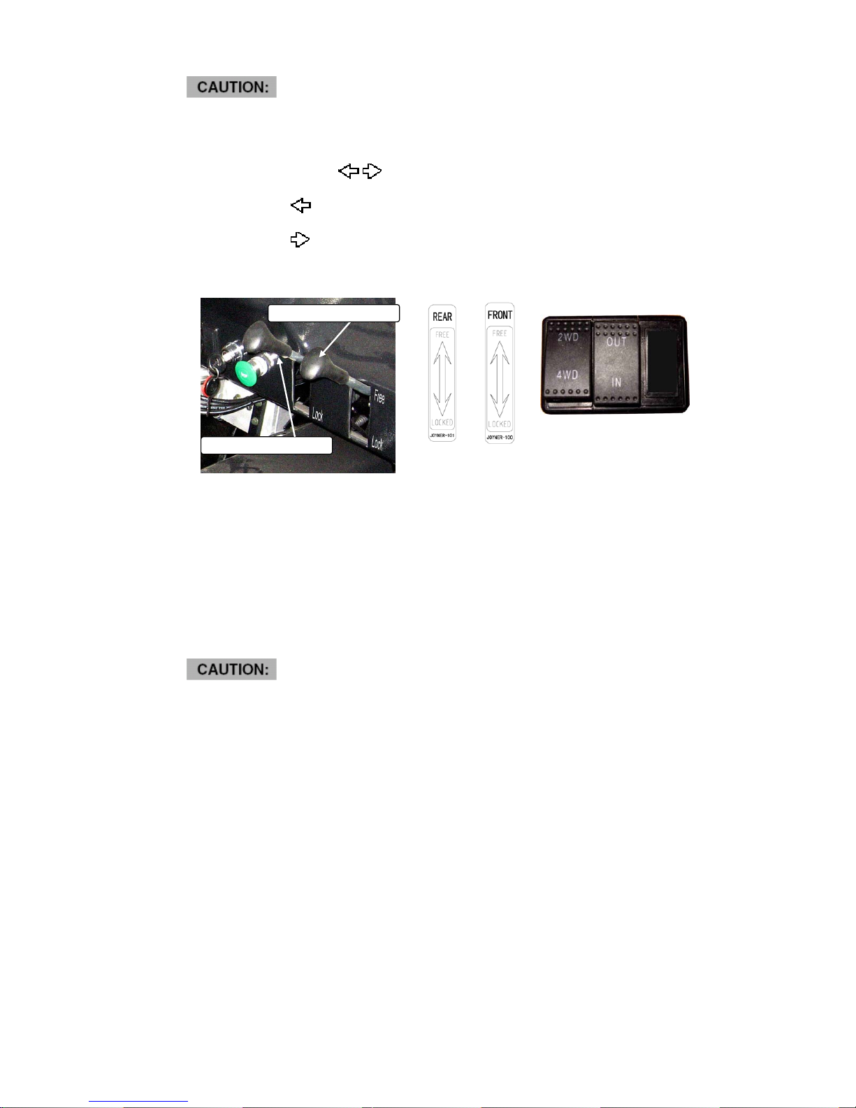
Four-wheel drive switch “2WD/4WD”
This vehicle is equipped with an on-command four-wheel switch "2WD/4WD" and 2
differential gear lock handles. Select the appropriate drive according to terrain and the
conditions
z (“2WD”) Power is routed to the back wheels only
z (“4WD”) Power is delivered to both the front and the back wheels.
z Front free: the vehicle working with front differential.
z Front lock: the vehicle working with front differential locked.
z Rear free: the vehicle working with rear differential.
z Rear lock: the vehicle working with rear differential locked.
z To change from 2WD to 4WD bring the vehicle to a complete stop set the gear in
neutral press the 4WD button and wait for the 4WD button to light up. After the button
lights up you can continue in four wheel mode.
z Injury or death may occur if change differential to differential locked at a high speed.
z Injury or death may occur if drive the vehicle at a high speed with both front
differential locked and rear differential locked
Rear diff lock handle
Front diff lock handle
Page 31

31
Winch switch “in/out”
Set the winch to IN to reel the cable in
Set the winch to OUT to reel the cable out.
Indicator lights
Reverse indicator light “R”
This indicator light comes on when the drive select lever is “R” reverse position.
Battery charging indicator light “ ”
This indicator light comes on when the generator of the engine can’t electricize the
battery. You should check the generator and battery or get help from your JOYNER
dealer.
Coolant temperature indicator light “ ”
It indicates the temperature of coolant. if the temperature is above 1020C/2150F, stop
engine immediately. Check coolant lever and add if low, see authorized JOYNER dealer
if temperature indicator stay on and overflow tank is full of coolant.
Oil pressure indicator light “ ”
It indicates over low/over high oil pressure when illuminated, see authorized JOYNER
dealer if necessary.
Steering wheel
Steering wheel is used to control the direction; it can be turned about third four rounds.
Be familiar with the steering wheel before driving,
and slow down less than 20 km/h when turn a
direction, or turning over may occur.
Check the steering wheel before driving, and
make sure it can work well, and front wheels can
turn according to the steering wheel.
Steering wheel
Page 32
32
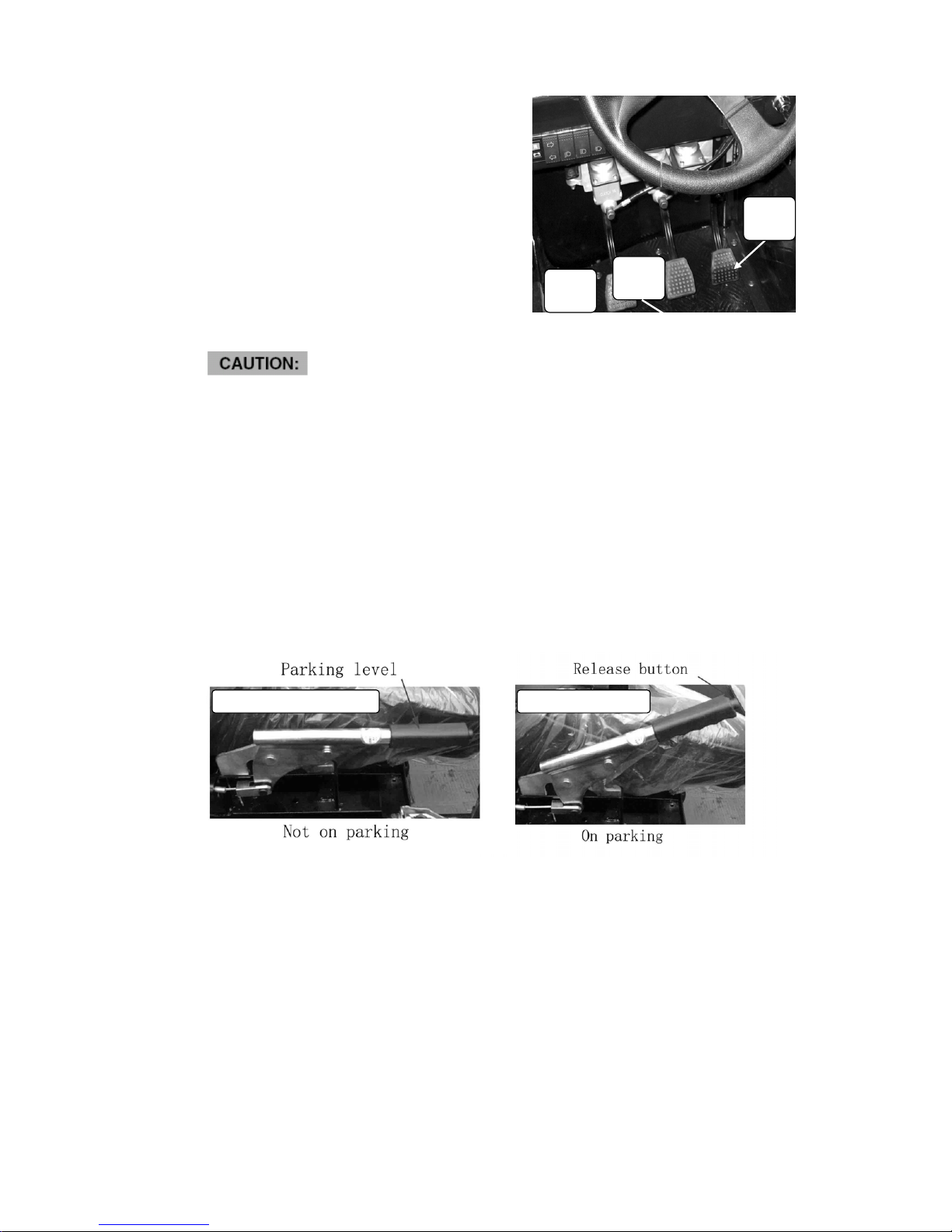
Pedal
Clutch pedal
The left foot pedal controls the clutch cable .
With the pedal down, you can shift the shift lever
Brake pedal
The brake is located in the middle of the three
control pedals .Applying pressure to the pedal
applies pressure to the brake caliper around
the brake disc at the front and rear wheels and
slows or stops the vehicle.
Throttle pedal
Press the accelerator pedal down to increase
engine rpm.
z Before start the engine, you should check the three pedal to be they are operating
smoothly.
z Before start the engine, you must make sure that the spring pressure can returns the
three pedals to the rest position fully when released.
z If anyone of them can’t work well, please correct the problem before operating the
engine .If you can’t find or solve the problem yourself, please get the help from your
JOYNER dealer.
z Improper operation of the clutch will lead to excessive wear of the clutch friction
surface.
z When operating the vehicle, if it does not feel comfortable about clutch or throttle
pedal , adjust the position of the pedal location sheet 1 and the pedal location sheet
2, tighten the nut until it feels very comfortable.
Parking brake lever
Pull the parking lever up so that the unit can engage park brake. To release the unit,
press button in the front end of parking lever, then push the parking lever to the bottom.
Clutch
Pedal
Brake
Pedal
Park brake not engaged Park brake engaged
throttle
Pedal
Page 33
33
z Adjust the parking cable if necessary.
z Be sure to fully release the parking brake lever before driving the vehicle.
z It is allowed use the parking lever as an emergency brake if the foot brake can’t
work.
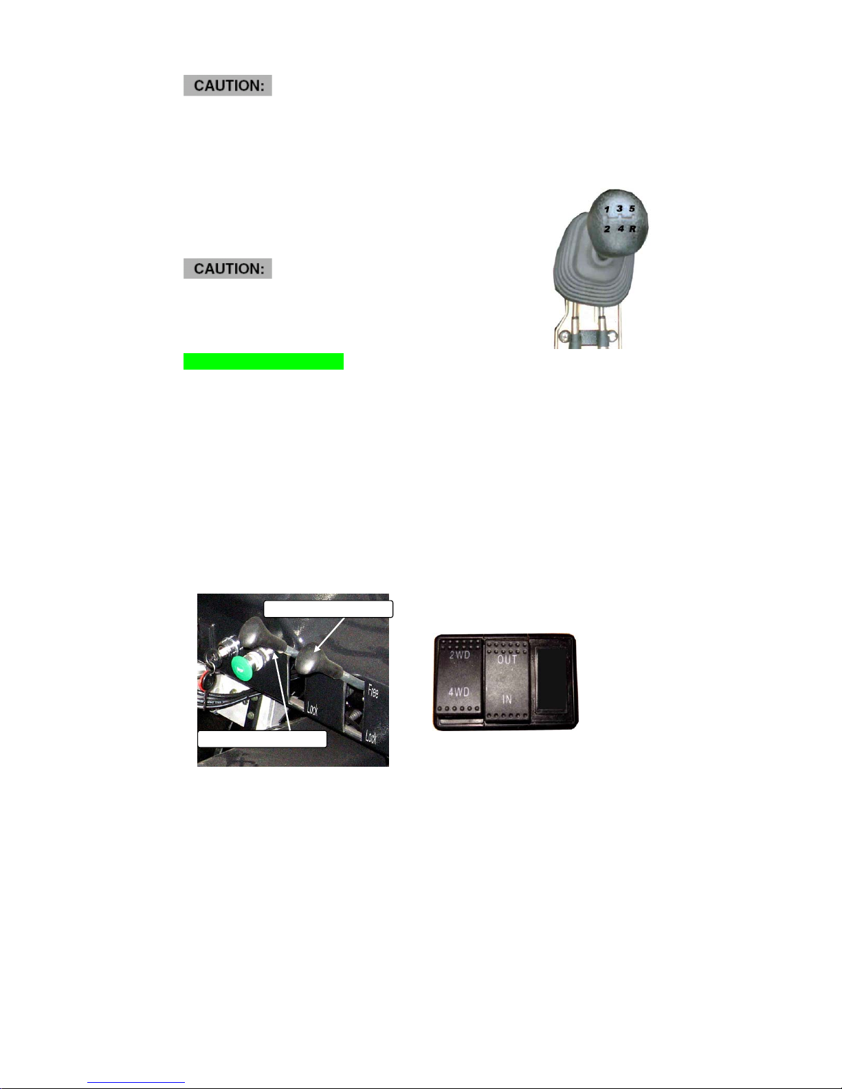
Drive select lever
The drive select lever is used to shift your
vehicle into the 1,2,3,4,5 and R gear positions.
z Never start the vehicle at 3, 4 or 5 gear
z Stop the vehicle fully before shifting to reverse.
z When reversing, the reverse indicator “R” comes on.
Differential control handle
Moving the differential control handle up and down to make the differential work and
locked, 2 handles control front differential and rear differential respectively. Choose the
work mode that you need according to the terrain situation. The following work mode is
available:
z 2DW(2 driven wheels):
1. Rear differential.
2. Rear differential locked
z 4DW(4 driven wheels):
1. Rear differential and front differential.
2. Rear differential locked and front differential.
3.
Rear differential locked and front differential locked
Shift the handles right side and pull down, then stop the handle in the differential locked
position.
Rear diff lock handle
Front diff lock handle
Page 34
34
Never use 4DW with both front differentials locked and rear differential locked at a high
speed, because the work mode of 4DW with both front differentials locked and rear
differential locked will make the steering hard.
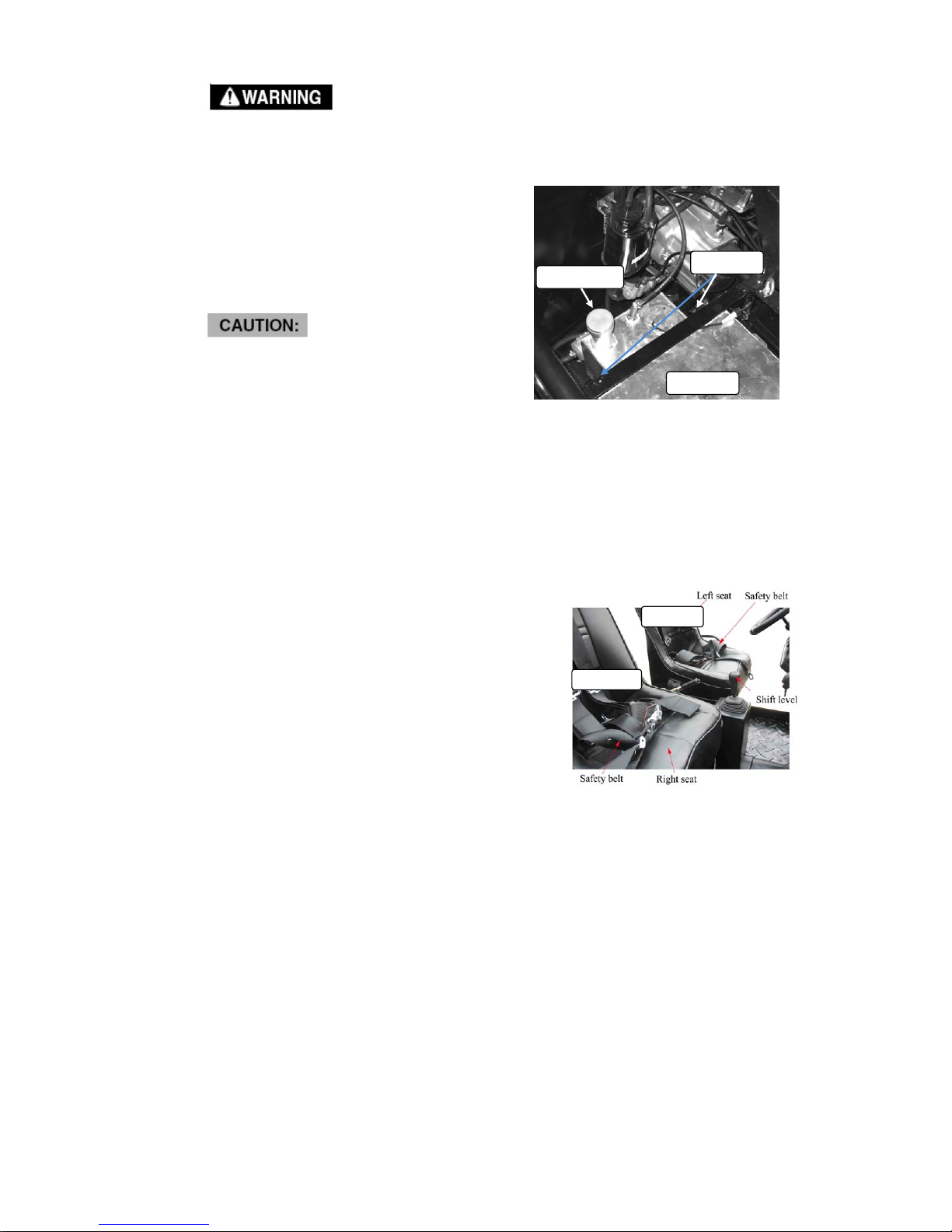
Fuel tank
Fuel tank locate under the passenger seat, and
fuel tank cap locate behind the passenger seat.
unlock Seat lock and turn passenger Seat over
before unscrew fuel tank cap.
add gasoline to about 80% of fuel tank.
z Never overfill the gas tank.
z Keep the fuel tank cap clean.
z Make sure to cover the key hole back
after use
z to prevent dirt from entering the lock mechanism
Seats and safety belts
Seats
To slide the seat back and forwards on the Trooper, pull the lever located in the front of
the seat upward, hold the lever in that position and adjust the seat to the desired position.
Be sure the adjustment lever is back on its full lock position and the seat is locked in
place.
1. Pull seat lock lever under left leg upward.
2. Move the Seats backwards or forwards
as your need.
3. Release the lock lever, so the Seat is locked
in the position you want.
To access the battery compartment the
compartment is located underneath the passenger
seat the seat can be lifted in the same manner
the cargo bed. Just unlock the quick release latches
located in the back of the seat.
1. Remove the safety belt hooks connecting to
the hoops bolted on the frame.
a) Press the limiting rock, make a space between
the hook and the hoop.
b) Take off the hook.
2. Repeat step 1, take off these hooks behind seat and both sides of seat.
3. Unlock the seat locker under the seat.
4. Turn the seat until it is stopped by steering wheel.
Fuel tank
Fuel tank cap
Seat lock
Left seat
Right seat
Page 35

35
Safety belts
This vehicle is equipped with five-point
seat belts for both driver and passenger.
Always wear the seat belt while riding in the vehicle.
To wear the seat belt properly, do the following:
1. Hold the latch plates as you pull the belts across
above right shoulder, left shoulder, right leg,
left leg and among two legs. Make sure the belt
is not twisted and is not caught on any portion
of the vehicle, your clothing, or any equipment
you are carrying (see right picture).
Cross above right
shoulder
Cross above left
shoulder
Cross above right leg
Cross above
left leg
Cross between 2 legs
Cross above
left leg
Back Hook
Limiting rock
Take off back hooks Take off side hooks
Turn around seat
Page 36

36
2. Push the latch plates into the buckle, use a
hook connects the end of the belt which crosses
left leg and set level. Pull up on the latch plates
to make sure it is secure (see right picture).
3. Position the shoulder belt over your shoulder
and the leg belt over your leg. The shoulder belt
should fit against your shoulder and the leg belt
should fit against your leg. If it is loose, pull the
belt out all the way and then let it retract.
4. To release the buckle, lift and release the hook.
z Before attempting to adjust the seat ensure that engine of TROOPER is stopped.
z Never operate TROOPER when the seat is not securely fastened, or may result in a
strong possibility of severe personal injury or loss of life. Before attempting to adjust
the seat ensure that TROOPER is stopped.
Safari bed
Safari bed can be lift up.
1. Pull up the release lever on the both side of
the vehicle,
2. Lift up the safari bed slowly until it stops.
3. Lower the safari bed slowly to its original
position and make sure it is locked tightly.
z Before closing the bed, be sure others are standing away from the vehicle. Keep
hands and fingers away from the pinch points between the bed and frame.
z The max load is 150Kg/330Ib.never exceed the stated maximum load limit for this
safari bed. or injury or
z Cargo should be properly distributed and securely attached. Reduce speed when
carrying cargo. Allow greater distance for braking.
Start engine
1. Engage the parking brake if necessary.
2. Pressing down the clutch pedal can make starting easier, so do that if necessary.
3. Make sure the shift lever in neutral position.
4. Turn the key clockwise to the “start” position and hold it for less than 5 seconds, if
Cross above right leg
Cross above
right shoulder
hook
Cross above
left shoulder
Page 37

37
engine not started. Repeat it until the engine is started. Release the key and the
clutch pedal when the engine starts. Keep engine running for 1-2 minutes before
driving.
z Do not attempt to start or operate the engine until completely familiar with the
location and use of each control necessary to operate this vehicle. The operator
must know how to stop this machine before starting and driving.
z Each time prior to starting the engine, check the throttle assembly to ensure that
when pedal is pushed all the way forward the assembly is working smoothly and
returns to idle when released. Do not operate if pedal or engine throttle linkage fail to
return to idle. If unable to correct the problem through lubrication, adjustment or
replacement of worn parts, contact your dealer for assistance.
z Before you start the engine, check that the parking brake is engaged, and the gear
shift lever is in neutral. Trying to start the engine in gear may damage the starter
motor, clutch or gearbox.
z Release the key at once if the engine starts. Holding the key in start position when
the engine is running will cause damage to the starter motor.
z If the engine does not start after 5 seconds, a second attempt to start the engine can
be allowed. Improper operation will damage the engine.
Stop engine
1. It is strongly recommended to stop vehicle before stop engine.
2. Make sure the shift lever in neutral position.
3. Turn the key clockwise to the “off” position.
z Before driving this vehicle, test the Engine Stop key to assure that it is operating
properly.
Passenger
The vehicle allows for two riders only.
The passenger should wear seat belt all the time.
Break-in
The first month is most important in the life of your vehicle. Proper operation during this
break-in period will help assure maximum life and performance from your new vehicle.
The following guidelines explain proper break-in procedures.
1. After the engine starts, the engine is not allowed in high speed in the neutral gearshift.
2. Drive vehicle from stop to low speed slowly.
3. Avoid braking strongly.
4. Do not exceed the vehicle speed on the below schedule.
Page 38

38
The speed of vehicle The first 1000 km
Max speed in each gear
1st Gear 12.4MPH
2nd Gear 24.8MPH
3rd Gear 37.2MPH
4th Gear 52.7MPH
5th Gear 65.1MPH
Starting and operating instructions
Before starting the engine, be sure that the driver is seated properly in TROOPER and
tighten the seat belts.
Testing TROOPER in a open place at the beginning to learn how to start, turn and stop.
Operate TROOPER slowly until you are familiar with it.
The turning radius of TROOPER is small and agile, so the centrifugal force is very high
when turning at high speed. Slow down to a more controllable speed when turning to
prevent TROOPER from rolling over.
To prevent vehicle from rolling over, be sure to only turn the vehicle at a slow more
controllable speed.
Page 39

39
Specifications
Model
TROOPER
Dimensions:
Overall length
Overall width
Overall height
Seat height
Wheelbase
Ground clearance
Minimum turning radius
3300mm/130 inch
1600mm/63 inch
1990mm/78 inch
800mm/34.6 inch
2470mm/97.2 inch
300mm/11.8 inch
6000mm/236 inch
Basic weight:
With oil and full fuel tank
780kg/1719 Ib
Engine:
Engine type
Cylinder arrangement
Displacement
Bore x stroke
Compression ratio
Starting system
Lubrication system
Liquid cooled—4stroke
Upstanding double cylinder
1080cc
72mm×66.5mm/2.83 inch x2.62 inch
9.5:1
Electric starter
Wet sumb
Engine oil
Type
Recommended engine ail
classification
Quantity:
With oil filter cartridge replacement
> 0 ℃ / ℉ SE15W/40, < 0 ℃ / ℉
SE15W/30
3.0L/3.17qt
Final gear case oil:
Type
Quantity
SAE85 API GL-5 gear oil
1.8L/1.9 qt
Radiator capacity(including all routes): 5.0L/5.28 qt
Air filter:
Engine
Intake duct
Wet element
Dry element
Fuel:
Type
Fuel tank capacity
Unleaded gasoline only
30L
Fuel system:
Type
EFI
Spark plug:
Type/manufacturer
S11-3707100/ Chery
Clutch type: Dry, diaphragm spring
Page 40
40
Transmission:
Transmission type
Operation
Manual
Right hand operation (five shifts,one
reverse)
Chassis
Frame type
Caster angle
Steel tube frame
3º
Tire
Type
Size front
rear
Tubeless
27 inch
27 inch
Brakes:
System
Type front
rear
Operation
Front and rear unified
Dual disc brake
Dual disc brake
Foot operation
Suspension:
Front suspension
Rear suspension
Independent Dual A-Arm
Longitudinal Control Arm
Shock absorber:
Front shock absorber
Rear shock absorber
Coil spring/oil damper
Coil spring/oil damper
Wheel travel:
Front wheel travel
Rear wheel travel
120mm/4.72inch
150mm/5.9inch
Electrical:
Ignition system
Generator system
Battery type
Battery capacity
Distributor block
AC magneto
Lead acid storage battery
12V 45Ah
Specified fuses:
High beam fuse
Low beam fuse
Turning light fuse
Tail light fuse
Brake light fuse
Reverse light
Gauge light
Engine main fuse
Fuel pump fuse
Fan fuse
7.5A
7.5A
5A
5A
5A
5A
7.5A
20A
15A
25A
Bulb voltage, wattage quantity:
Headlight
Tail/brake light
12V 35W/35W×2
12V 5W/21W×2
Page 41

41
Spotlight 12V 35W/35W×4
Indicator lights:
Reverse indicator light
Coolant temperature warning light
Charge indicator light
Four-wheel-drive indicator light
LED
LED
LED
LED
Page 42
42
Maintenance and adjustment
Air Cleaner
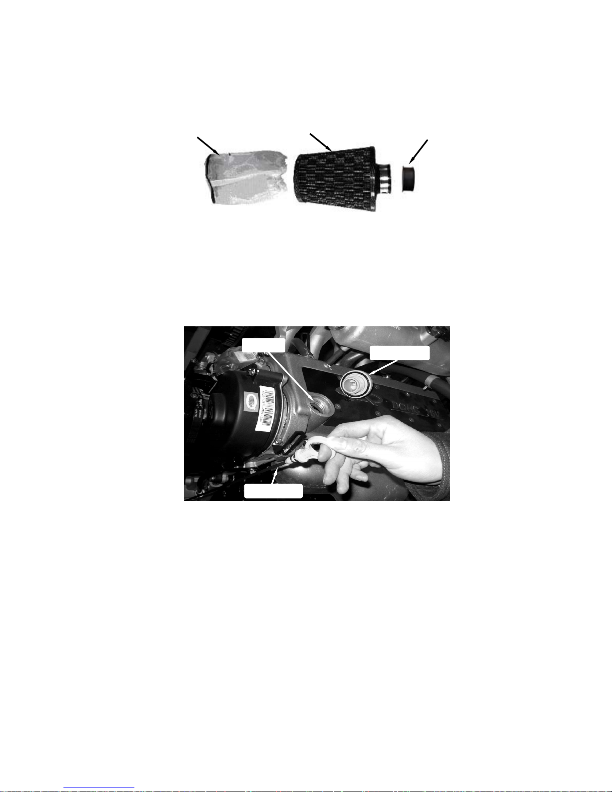
Clean air filter refer to Preventative maintenance and service log. Under dusty conditions
Service more often
Remove filter cover; check the filter cover and the air filter, if dusty, blow off dust with
clear and dry air. If necessary, replace with a new one.
Engine Lubrication
1. Engine oil replacement
You must change the oil in the crankcase refer to Preventative maintenance and service
log. That will insure proper lubrication of internal parts and prevent costly repairs due to
excessive wear.
Oil inlet plug
Cover
Filte
r
Rubber bushing
Oil inlet
Oil measurer
Page 43
43
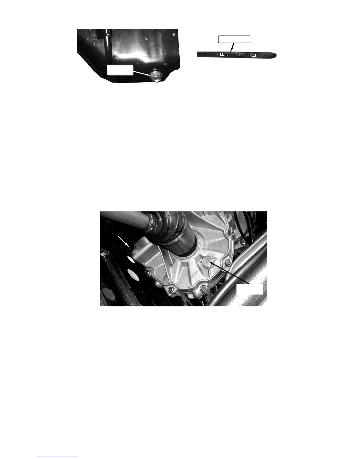
a. With the engine warm, put the vehicle on the level ground.
b. Shut down the engine; put a collecting oil plate under the engine oil outlet. Loosen
the oil outlet plug in the warm engine. Let the engine oil out fully.
c. Tighten the engine oil outlet plug.
d. Remove the oil filler cap, fill oil (SAE 10W/30-50) about 3.86 liters to the engine.
e. Pull out the engine oil dip stick; confirm the corrective oil level in the crankcase.
2. Check engine oil and recharge
If the color of engine oil changes, you need to replace the engine oil as above.
Check the engine oil level; charge if the oil level is lower than “L”.
Transmission lubrication
Oil replacement
You must change the oil in the transmission refer to Preventative maintenance and
service log. That will insure proper lubrication of internal parts and prevent costly repairs
due to excessive wear.
a. Put the vehicle on the level ground.
b. Shut down the engine; put a collecting oil plate under the transmission oil outlet.
Loosen the oil outlet plug in the warm engine. Let the transmission oil out fully .
Oil inlet
Oil outlet
Oil measure
Oil outlet
Page 44
44
c. Remove the iron dust plug, this plug has a magnet on it. Iron dust caused by
moving parts will stick to the plug. Clean the iron dust from this dust plug .
d. Tighten the transmission oil outlet plug and the iron dust plug.
e. Remove the plug, fill oil (API 80(75) W-90 GL-3 Gear Oil ) about 2.0 liters.
Differential lubrication
Oil replacement
You must change the oil in differential refer to Preventative maintenance and service log.
That will insure proper lubrication of internal parts and prevent costly repairs due to
excessive wear.
a. Put the vehicle on the level ground.
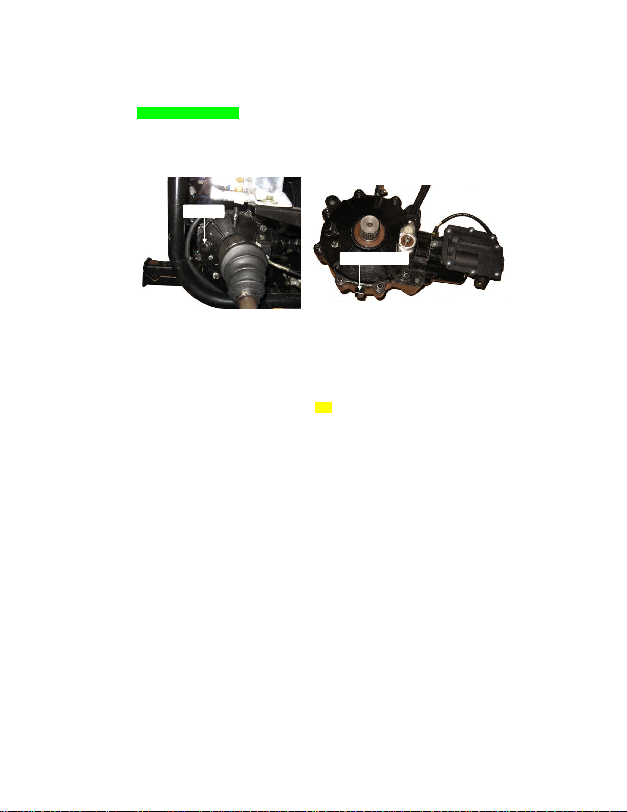
b. Shut down the engine; put an oil container under differential oil outlet plug. Loosen
the oil outlet plug in the differential. Let the oil out fully.
c. Remove the iron dust plug, this plug has a magnet on it. Iron dust caused by moving
parts will stick to the plug. Clean the iron dust from this dust plug.
d. Tighten the differential oil outlet plug
e. Remove the oil inlet plug; fill oil (API 80(75) W-90 GL-3 Gear Oil) about 0.4 liters.
f. Replace the oil inlet plug, and tighten with 30N*m torque.
g. Change the oil in front differential with the same steps.
Engine Coolant
Add Coolant
You must check the coolant for level and leaks. If it is low, you need to refill coolant into
the radiator (approximately 6000 ml). The lack of coolant will cause the engine to
overheat. This can cause engine damage.
The coolant should always be topped up, since the coolant can evaporate.
Oil inlet
Oil outlet plug
Page 45

45
a. Put the vehicle on level ground.
b. Lift up the red release lever, release the pressure inside.
c. Turn the coolant cap counterclockwise and open the cap.
d. Pour fresh coolant to filler neck. Start the engine at idle.
e. Increase the engine rev’s a few times.
f. Repeat 2, 3, and 4 till the coolant is at neck and no bubbles come up.
g. Refit the coolant cap, turn it clockwise and tighten it.
h. Turn the reserve coolant case cap counterclockwise and open the cap.
i. Pour fresh coolant of the specified type into the reserve coolant tank till the coolant
reaches 2/5 to 3/5 of the reserve coolant tank volume.
j. Close the reserve coolant case cap, turn it clockwise and tighten it.
z Opening the radiator cap while the engine is hot can be hazardous.
Opening the radiator cap can spray the high temperature coolant in your eyes, face
and any parts of your body. This can result in severe injury. Never open the radiator
cap while the engine is hot.
z Children and pets may be harmed by coolant.
Keep coolant away from the children and pets.
z Continuous or brief contact with coolant may be dangerous for your health.
Wear a long sleeve shirt and moisture-proof gloves (such as dishwashing gloves)
when you change coolant. If coolant contacts your skin, wash thoroughly with soap
and water. Wash any clothing or rags if wet with coolant.
z Recycle or properly dispose of used coolant.
Release lever Release lever
Cap
Page 46
46
z harm or damage may occur if use coolant that does not meet the specification.(50%
standard green coolant and 50%distill water)
Idle Speed
Adjustment
Never make unnecessary adjustments. The factory recommended settings are correct
for most applications. It’s not necessary to disassemble the screw unless the idle speed
needs to adjustment.
Warm up the engine (5~10min)
a. Connect the tachometer; adjust the throttle
to limit the idle speed. The standard value is
(900±RPM).
b. Adjust the screw and adjust the idle speed
to an ideal value.
c. Repeat step b until the RPM of engine
stables.
Spark plug inspection
z Clean spark plug
Check spark plug refer to Preventative maintenance and service log, if too much carbon
adhered, which will weaken the spark.
Clear the carbon adhered with a dry brush, and scratch the carbon adhered to insulating
lay carefully with a file. And blow of dust with dry and clear air. And adjust the space to
0.9~1.1mm/0.035~0.043inch.
z Spark plugs replacement
The spark plugs should be replaced every 30000km/18641miles, or 18 months.
Screws
Screws
Plastic cove
r
Spark plug seat
Plastic cover
A
djustment screw and nut
Page 47

47
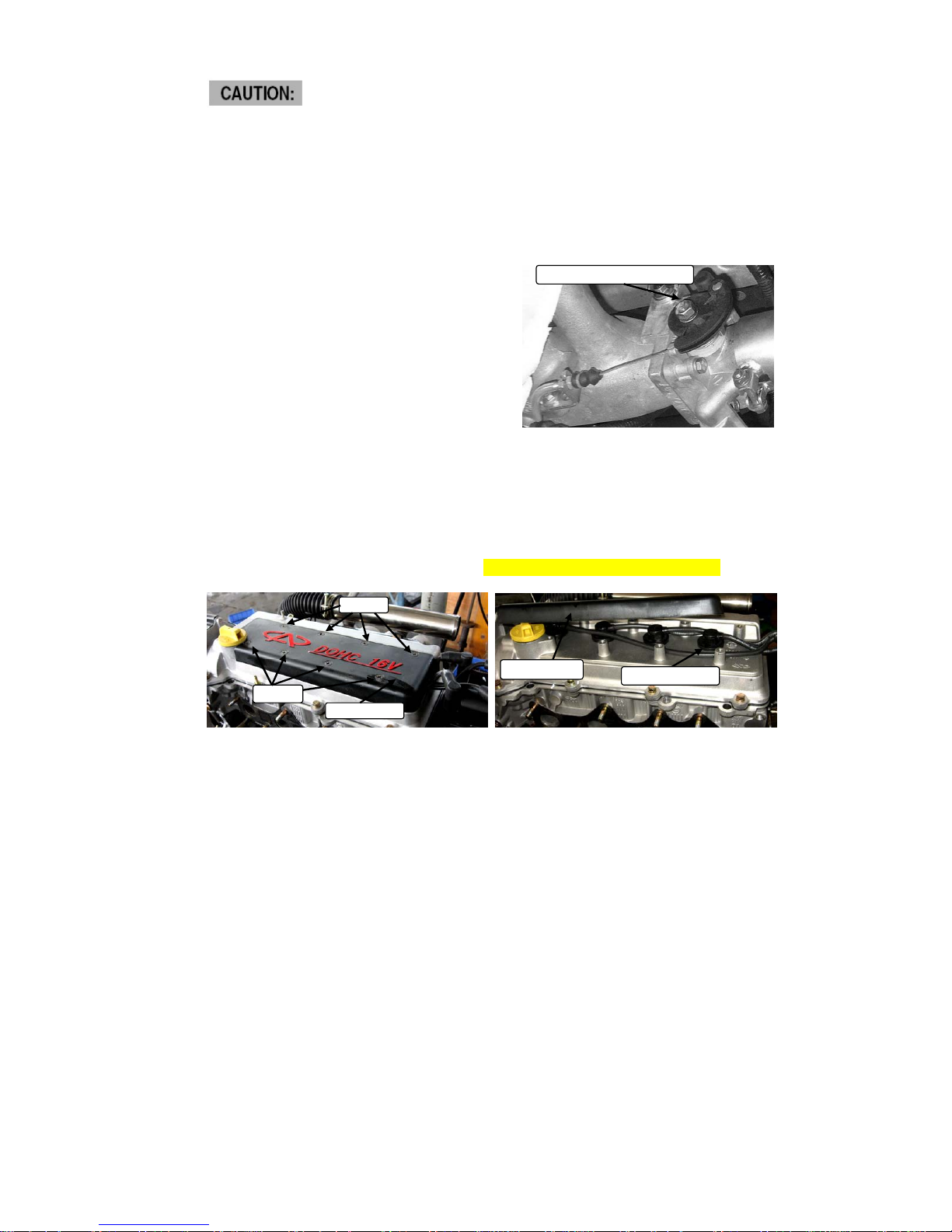
1. Unscrew 8 screws and take off spark plug plastic cover.
2. Clean the dust in the spark plug seat.
3. Pull off the high-voltage wire,remove the spark plug with a special spanner.
4. Insert a new spark plug or a cleaned spark plug, and turn a few rounds clockwise, if
retardarce happen, take it off and try it again to make sure screw engaged correctly.
5. Tighten spark plug with a special spanner (torque:25N*m/18.4Ft-Lb )
6. Connect high-voltage wire in order.
Engine damage or working unsteadily may occur if:
1. Not install the spark plug correctly.
2. Use a forbidden spark plug.
To avoid damage, follow the following items
1. Tighten spark plug to a required torque (25N*m), over tightening will damage the
screw.
2. Removing or installing a spark plug, make sure the slot aligned.
3. Do not pull the high-voltage wire, pulling the tube wrapping the high-voltage wire is
allowed.
4. Other brands of spark plug are forbidden.
0.9~1.1mm
0.035~0.043inch
Special spanner
Spark plug seat
Page 48

48
5. Make sure spark plugs hole lip is clear.
6. The spark plugs is hot after a long-time driving, make sure the spark plugs is not hot
before operation.
Wedge belt figure
Correct installation and the proper tension will ensure electrical generator and air
conditioner work well. If chap, tear, wear,or looseness happen, contact Joyner dealer
and replace it immediately.
Check the belt tension:
Apply a pressure (about 100N/22.48lbf) on the belt, if the movement is more than
10mm/0.4inch, it is necessary to replace the belt.
When checking the wedge belt, never start engine, or body injury even death may occur.
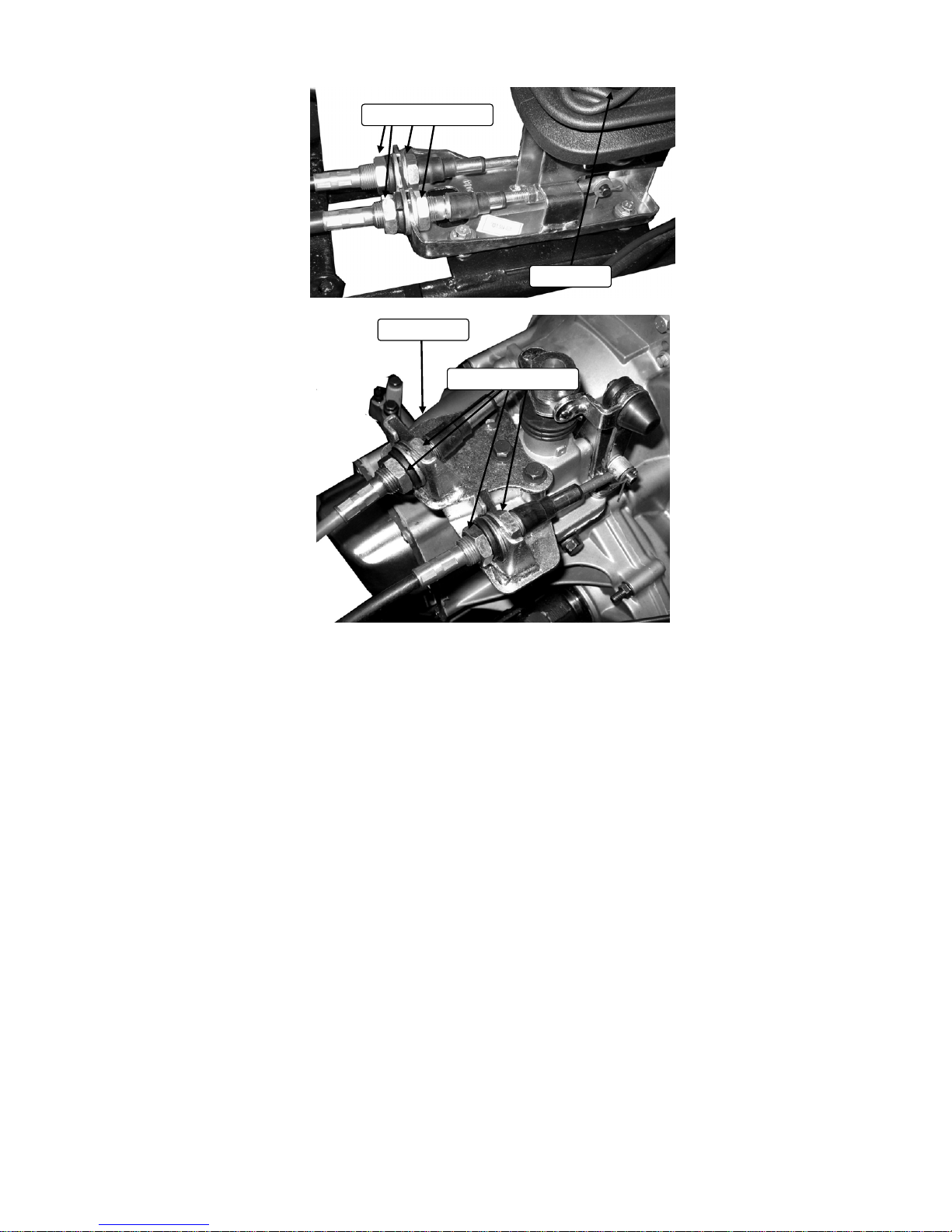
Shift cable adjustment
After a long time use, more and more free play of shift cable make gear position is not
accurately or shift lever in a wrong position, so adjust the shift cable refer to
Preventative maintenance and service log.
1. Loosen the adjustment nuts, move the cable forwards or backwards
according situation, repeat it until find a position where gear shift work correctly
and the shift lever work in a proper position.
2. Repeat step 1 with another shift cable.
3. Tighten all of the adjustment nuts.
10mm/0.4inch
Page 49
49
Parking brake cable adjustment
After a long time use, more and more free play of parking brake cable make parking
brake power decrease, so adjust the shift cable refer to Preventative maintenance and
service log.
1. Loosen the adjustment nuts, move the cable forwards or backwards
according the situation, repeat it until find a position where free play is gone.
2. Tighten all of the adjustment nuts.
Adjustment nuts
Adjustment nuts
Shift lever
Transmission
Page 50

50
Steering lubrication
Proper lubrication will ensure steering box work well and longer time. Please lubricate
the steering box refer to Preventative maintenance and service log.
To lubricate the steering box
1. Take the steering box off from TR1100 firstly, unbolt these nuts and bolts showed in
the following picture, pull off the steering joint, and take off the steering box slowly.
2. Inject lithium base grease about 20g through grease cup with a grease gun.
3. Clean the steering box, and install it with reverse step 1.
Adjustment nut
Adjustment nut
Parking brake lever
Unbolt the nut
Unbolt the bolt
Unbolt the bolt
Pull off the joint
Page 51
51
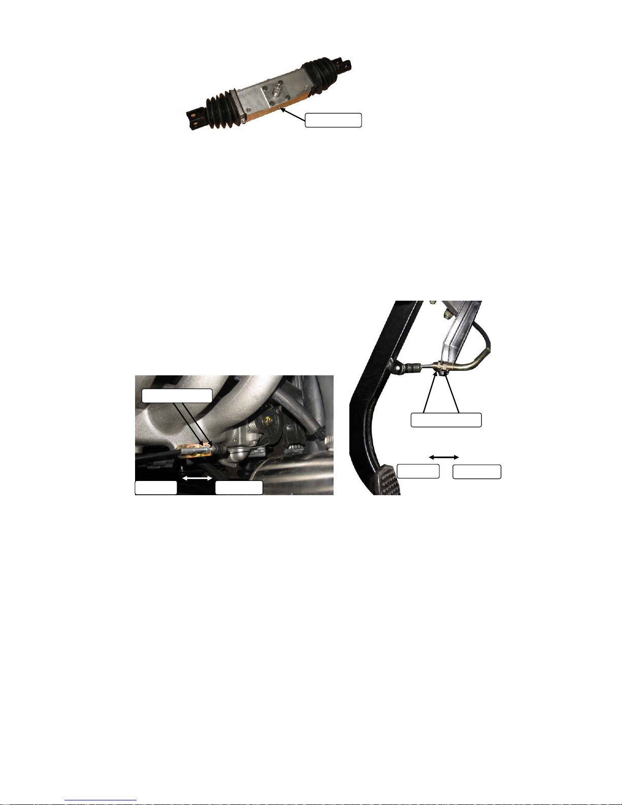
Throttle cable adjustment
After a long time used, the throttle cable may be too loose to work well, so adjustment is
needed. It is recommended to adjust the throttle cable refer to Preventative maintenance
and service log.
To tense the cable
1. Unbolt the engine-end adjustment nuts shown in the following picture, and move the
cable end forwards to make the cable in a proper tension, and tighten 2 adjustment
nuts, if the movement is not enough, following step 2 is necessary, or not necessary.
2. Unbolt the pedal-end adjustment nuts shown in the following picture, and move the
cable end backwards to make the cable in a proper tension, and then tighten 2
adjustment nuts.
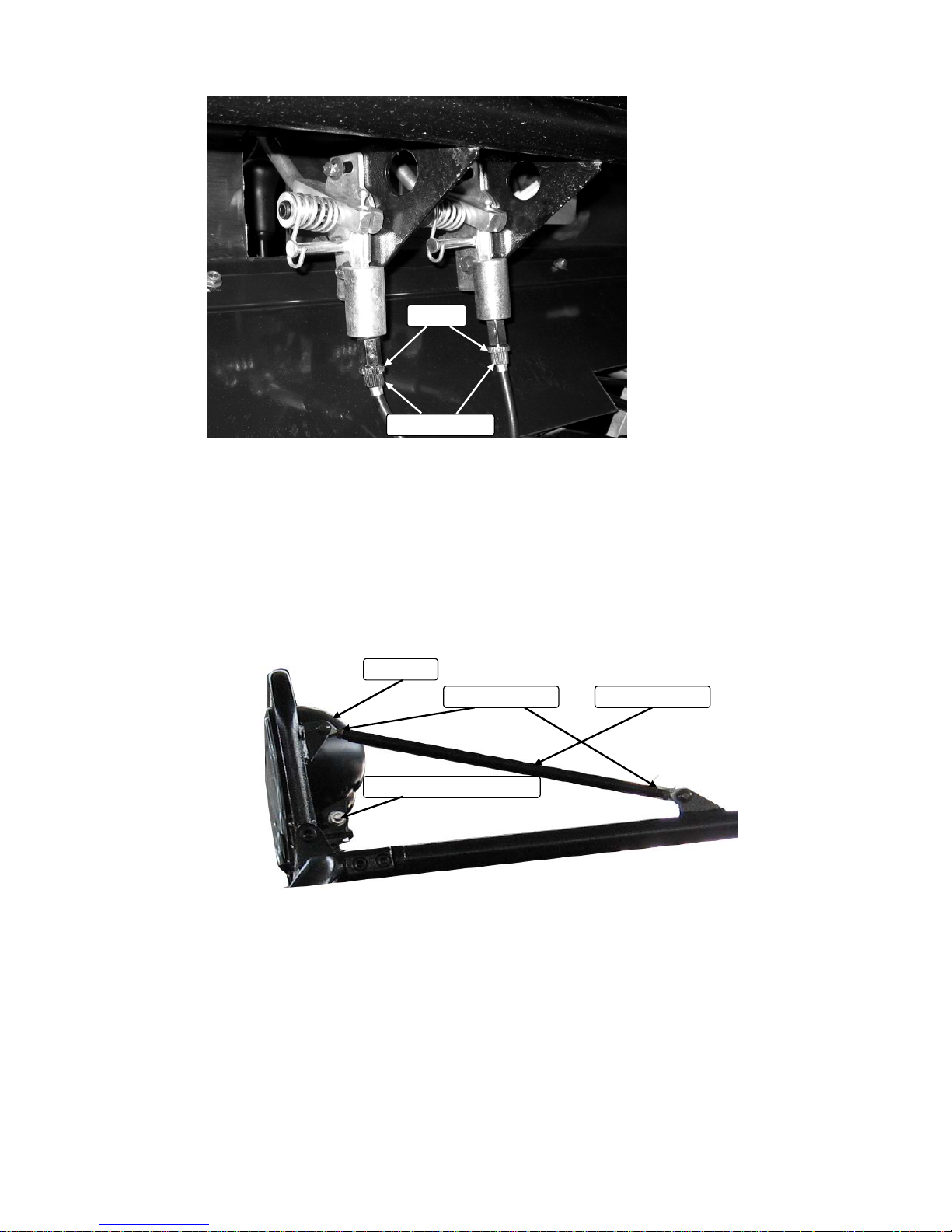
Differential lock cable adjustment
After a long time used, the throttle cable may be too loose to work well, so adjustment is
needed. It is recommended to adjust the differential lock cable refer to Preventative
maintenance and service log.
To tense the cable
1. Loose these 2 thin nuts, and then turn the screw sleeve counterclockwise a few
Grease cup
Adjustment nut
Adjustment nut
Forwards Backwards
Backwards
Forwards
Page 52
52
round until the cable get a proper tension.
Spot light adjustment
To get the desired spot-light position, adjust as following steps:
Solution 1
1. Loosen the spot light adjustment nut, and turn the spot light forwards and backwards
until find the desired position.
Solution 2
2. Loosen the adjustment nuts on at the both ends of spot light lever, and then rotate
the lever clockwise to pull the spot light support up, or counter clockwise to push the
spot light support down.
Screw sleeve
Thin nut
Adjustment nut
Spot light adjustment nut
Adjustment nut
Spot light
Page 53

53
Oil filter change
It is recommended strongly to change the oil filter refer to maintenance and service log.
To change the oil filter, just take off the oil filter with a special oil filter spanner showing in
the following picture, and replace it with a new one.
Fuel pressure adjustment
Never make unnecessary adjustments. The factory recommended settings are correct
for most applications. The recommend fuel pressure is 3.5kgf/m2 (49.8 psi). It’s not
necessary to adjust fuel pressure unless the fuel pressure really needs to be adjusted.
To adjust the fuel pressure:
1. Loose the lock-nut with a 14mm spanner as the following picture.
2. Turn the adjustment-bolt clockwise with a inner hexagon spanner to increase the fuel
pressure, and counterclockwise to decrease the fuel pressure.
3. Keeping one eye on the fuel pressure indicator while turn the adjustment-bolt, when
the indicator shows about 3.5kgf/m2 (49.8 psi), stop turning, and tighten the lock-nut.
Oil filter spanner
Oil filter spanner
14mm spanner
Lock nut
Inner hexagon spanner
Adjustment bolt
Page 54
54
Front Wheel Replacement
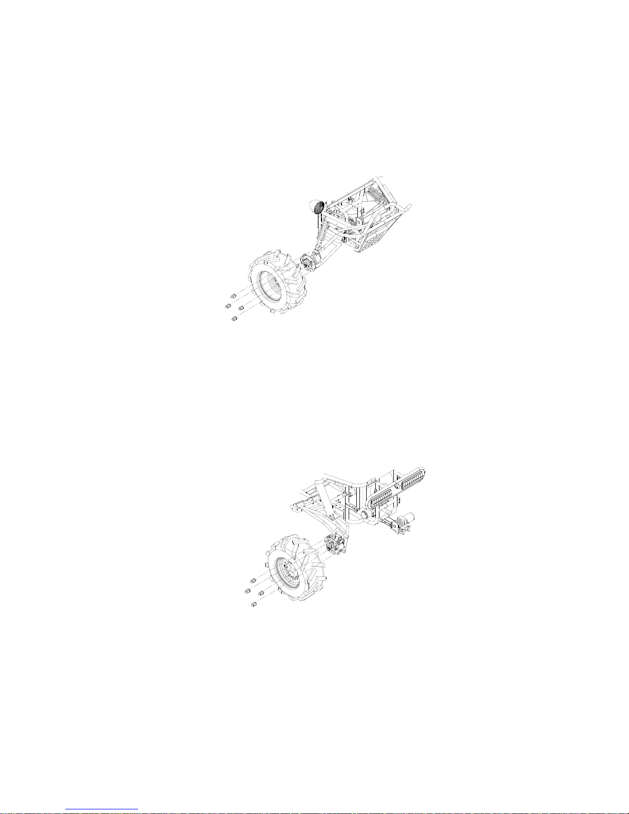
It is not needed to disassemble the center castle nuts when you replace the front wheels
or the rear wheels. Just take off these 5 cap-nuts, and replace the wheels with a new one.
Tighten these 5 nuts after replacing the wheels, the wheel need to be assembled by a
JOYNER authorized dealer.
Castle nuts
Torque:180±5 N*M/182±3.5FT_LB
Wheel nuts
Torque:70±5 N*M/51±3.5FT_LB
Rear Wheel Replacement
It is not needed to disassemble the center castle nuts when you replace the front wheels
or the rear wheels. Just take off these 5 cap-nuts, and replace the wheels with a new one.
Tighten these 5 nuts after replacing the wheels, the wheel need to be assembled by a
JOYNER authorized dealer.
Castle nuts
Torque:180±5 N*M/182±3.5FT_LB
Wheel nuts
Torque:70±5 N*M/51±3.5FT_LB
Page 55
55
Clutch replacement
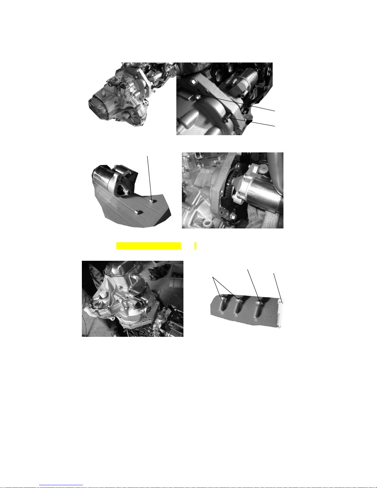
1. Remove two bolts, and demount Starter-assembly carefully.
2. Remove four bolts on the transmission case, lay down these carefully. Caution: When
fix the four bolts in the transmission case; you must tighten them according to the
prescribed torque 45-55 N*M/33-40.5 Ft-Lb.
Q1840845
Q1841245
S11-37081
Q218B1245
Q1841240
Q1841245
Page 56
56
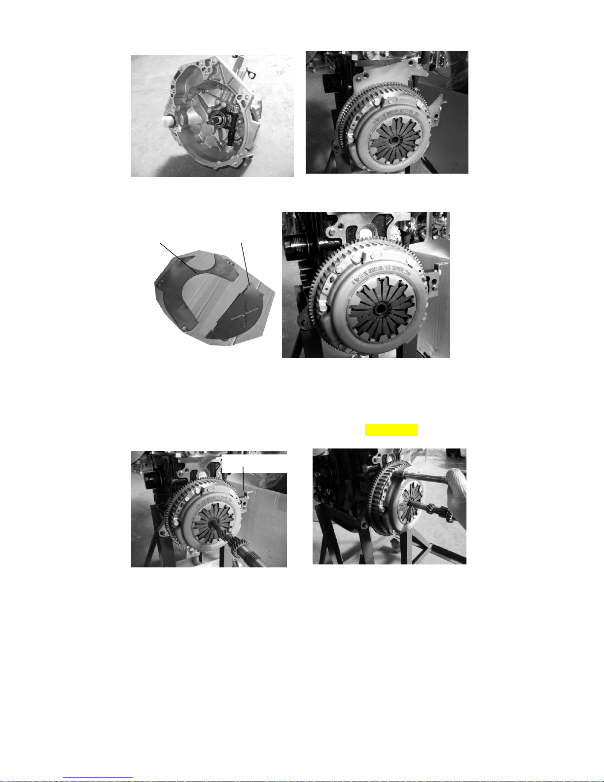
3. Remove upper steel cushions and lower steel cushion.
4. Insert a spine-shaft into the hole of the Clutch assy , remove the six bolts on the Clutch
pressure plate, now It’s clear. Caution: When fix the six bolts in the Clutch pressure
plate;
You must tighten them according to the prescribed torque 20.5 Ft_Lb
S11-170010372-100203
Spline-shaft
Page 57

57
5. Insert a spline-shaft into the hole of the Clutch assy, fix the six bolts on the Clutch
pressure plate, and tighten them according to the prescribed torque 20.5 Ft_Lb.
S11-1601020 S11-1601030
FIGURE 1
Page 58
58
6. Fix parts according to reverse operation to the disassembly.
Front Wheel Alignment
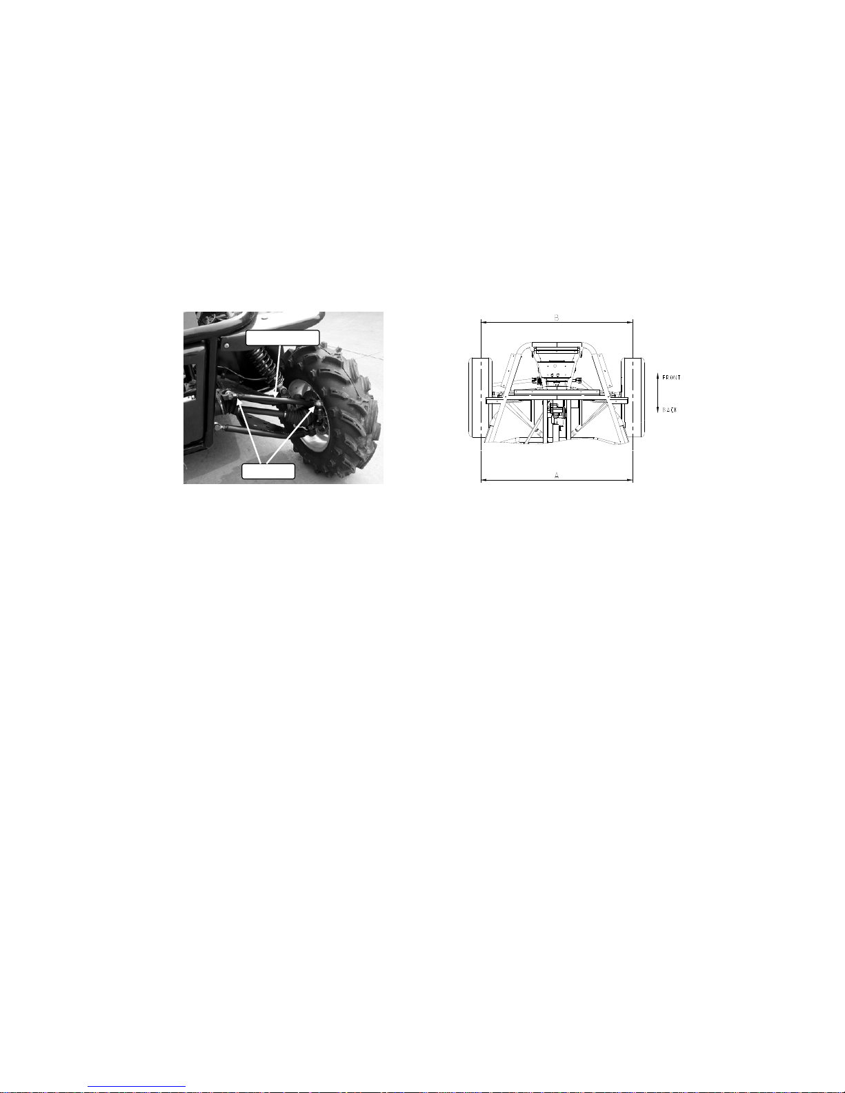
Correct front wheel alignment can ensure the vehicle run in a good track. After a long
time use, doing some alignment work is needed.
a. Put the vehicle on level ground.
b. The “toe-in” of the front wheels should be 0.98 inch. It means the dimension A should
be 0.98 inch more than dimension B.
c. Turn the steering wheel to align the center of the steering-rack with the center of the
frame.
d. Loose the lock nuts on both ends of Front Tie Rods. Turn the 2 tie-rods forwards to
increase A and decrease B, backwards to decrease A and increase B. repeat it until
the dimension A and B meet the requirement described as item a. and then tighten
all the lock nuts on the both end of tie-rod.
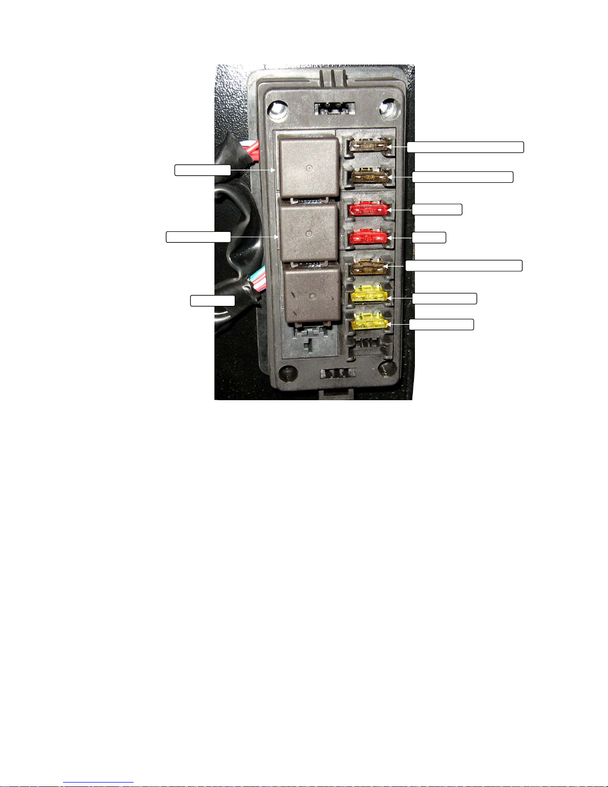
Fuse and relay
To check or replace fuses:
1. Take off the cover of the fuse box. Press the hook down and pull off the cover.
2. Check and replace the fuse according the fuses and relays diagram.
Lock nut
Front tie rod
Page 59

59
Front fuse and relays box
Spot light relay
High beam light relay Dipped beam light relay
Flash relay
Night light fuse
R gear indicator fuse
Brake indicator fuse
Turning single fuse
Head light fuse
Dipped beam fuse
High beam fuse
Horn fuse
Spot light fuse
Press the hook down
Page 60
60
Rear fuses and relays box
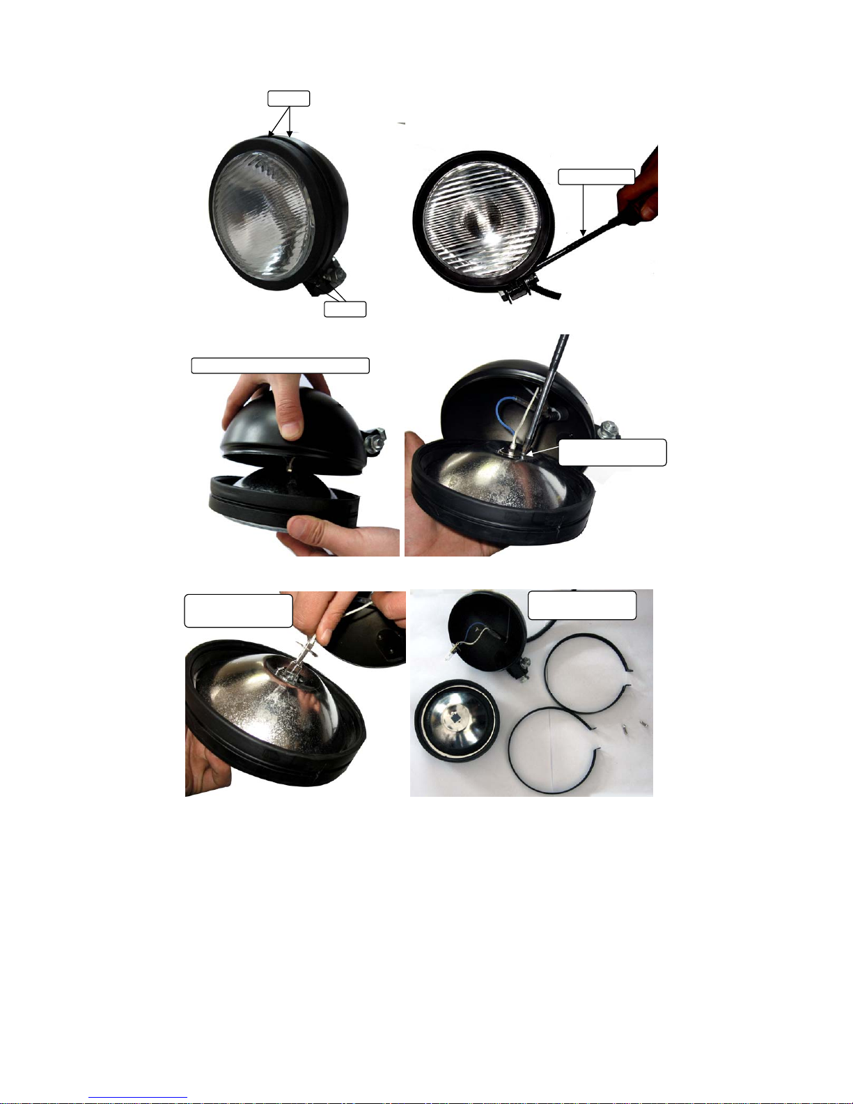
Bulb replacement
To replace the bulb of the head light:
1. Loose the 2 crews at the bottom of the head light, and take off the 2 hoops around
the head light.
2. Separate the head light as the picture.
3. Unscrew the screw that fixes the bulb, and take off the bulb carefully.
4. Disconnect the bulb from the wiring.
5. Connect a new bulb with the same specification to the wiring.
6. Put all the parts disassembled above with reversing step 1~4.
Engine relay
Fuel pump relay
Fan relay
ECU normal open circuits fuse
Gauge and indicator fuse
EFI fuse
ECU normal close circuits fuse
Fuel pump fuse
Engine fuse
Fan fuse
Page 61
61
Hoop
Screw
Screw driver
Separate the head light carefully
Unscrew the bulb
scre
w
Take off the bulb
carefully
Separate the head
li
g
ht like this.
Page 62

62
To replace the bulb of the taillight:
1. Unscrew the 6 screws from the taillight.
2. Separate the taillight cover from the taillight body.
3. Take off the bulb you need to replace through turning the bulb counter clockwise
about a half round, and replace a new one.
4. Put all the parts back with reversing step 1~2.
Shock adjustment
After a long time use, the shock need to be adjusted for more tension refer to
maintenance and service log, adjust the shock with a special spanner. In other case, the
chock nitrogen needs to be added to get more nitrogen pressure; the recommended
nitrogen pressure is 1.0MPa/145psi.
Adjust the shock refer to the following drawing.
Screw
Taillight cove
r
Taillight body
Page 63

63
set up
set up
S(mm)
P(N)
40 0
50
6793
Front shock spring specification
115
1563
3518
S(mm)
P(N)
35 0
11299
155
2551
Rear shock spring specification
1. Loose the lock nut on the top of the shock spring, and then turn the pushing-nut
clockwise to increase tension, and counter clockwise to decrease tension.
Lock nut Pushing nut
Special spanner
Clock wise
Special spanner
Page 64
64
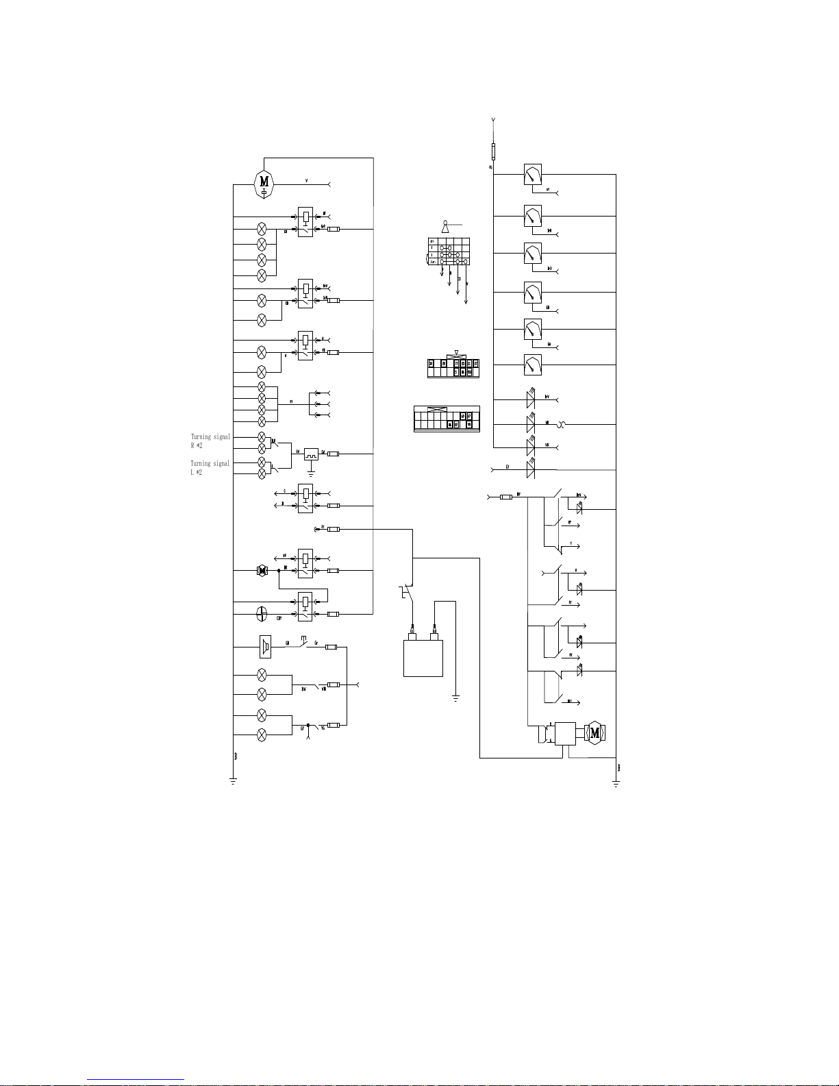
Chassis wiring diagram
High beam switch 1
High beam R
High beam L
Far beam relay
F
u
s
e
7
.
5
A
Dipping switch 1
dipped beam R
Dipped beam relay
Fuse 7.5A
dipped beam L
Clearance lamp
side light *4
Dipping switch 2
High beam switch 2
Turning signa
l
R *
2
Turning signa
l
L *
2
Turn signal
switch
s
c
i
n
t
i
l
l
a
t
o
r
Fuse 5A
Spot relay
F
u
s
e
1
5
A
Spot switch 1
spot light*4
G
Fuse 15A
F
u
e
l
p
u
m
p
r
e
l
a
y
F
u
e
l
p
u
m
p
Fuse 15A
F
a
n
r
e
l
a
y
C
o
o
l
i
n
g
f
a
n
Fuse 20A
M
a
i
n
r
e
l
a
y
P
o
w
e
r
f
o
r
E
C
U
Body wiring conn 67
Body wiring conn 82
Body wiring conn 69
Body wiring conn 82
Ignition switc
h
Battery
ST
IGN 1
IGN 2
F
u
s
e
7
.
5
A
S
p
e
e
d
m
e
t
e
r
T
a
c
h
o
m
e
t
e
r
F
u
e
l
m
e
t
e
r
O
i
l
p
r
e
s
s
u
r
e
g
u
a
g
e
S
p
e
e
d
s
e
n
s
o
r
W
a
t
e
r
t
e
m
p
e
r
a
u
t
e
r
m
e
t
e
r
V
o
l
t
a
g
e
m
e
t
e
r
I/p wiring conn 21
Fuelsensor
oil pressure switch
oil pressure
sensor
Body wiring conn 30
oil pressure
warning
water temperatuer
warning
Charge indicator
Body wiring conn 28
water temperture Swich
Reverserwarning
F
u
s
e
5
A
High beam
switch
Spot light switch 1
Dipping beam
switch
Spot light
switch
Brakes light R
Brakes light L
Fuse 5A
Brakes light switch
Fuse 5A
Horn button
Horn
button
+
-
Master switch
Spot light signal
IGN 1
Battery
IGN 1
Start motor
ST
4WD
Convertor
switch
Convertor
Capstan switch
Capstan
relay
Reverse light R
Reverse light L
Fuse 5A
Reverse light switch
Body wiring conn
I/p wiring conn
I/p wiring conn 23
I/p wiring conn 27
Spot light switch 2
Spot light switch 2
High beam
switch
Dipping switch 2
High beam switch 1
High beam switch 2
Dipping switch 1
High beam indication
Dipping beam signal
High beam switch 3
High beam switch 3
ING 2
IGN 2
Wire's colour symbol
B---black R---red BL---blue W---white Y---yellow V---Violet G---Green Br---brown K---pink OR---Orange Gr---Grey CB---Cambridge blue
RB---red/black BrB---brown/ Black GY---green/yellow BR---black/red WG---white/green GB---green/black WR---white/red BW---black/white
YG---yellow/green
GND
Reverse light switch 1
Reverse light switch 1
Fuse 20A
Body wiring conn 99
Page 65

65
Engine wiring diagram
Page 66
66
Engine disassembly, installation and repair
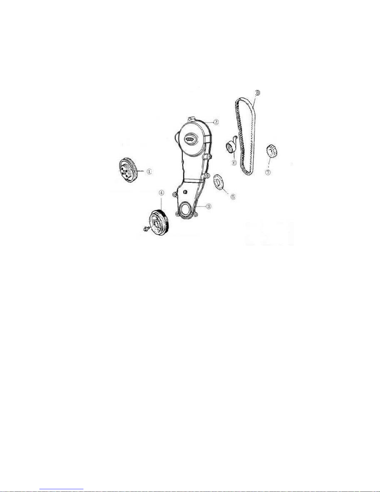
Timing Belt
1. Configuration diagram
1 Water pump pulley 2 Timing belt cover. upper 3 Timing belt cover. Lower 4 Torsion
shock absorber 5 Timing pulley damper 6 Tensioner 7 Crankshaft timing pulley .8 Timing
belt
Page 67
67
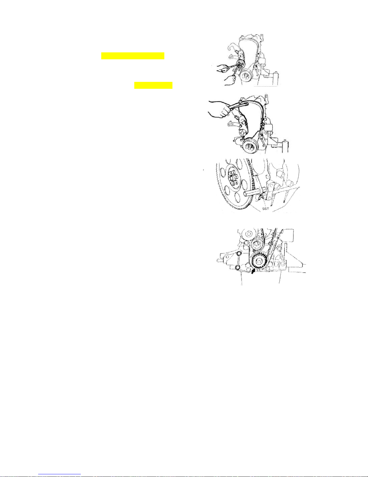
2. Disassembly
2.1. According the right picture, remove
water pump pulley
Torque: 25±1.5 N*m/18.5±1Ft_Lb
2.2. Removing timing belt cover
Torque: 6±1N.m/18.5±0.7Ft_Lb
2.3. Remove tensional vibration damper
2.3.1. Fix the flywheel and prevent the
gear ring from rotating,
2.3.2. Remove bolt of tensional vibration
damper.
2.3.3. Ensure the mark on the timing belt
match the mark on the oil pump
2.4. Remove timing belt covers
Page 68
68
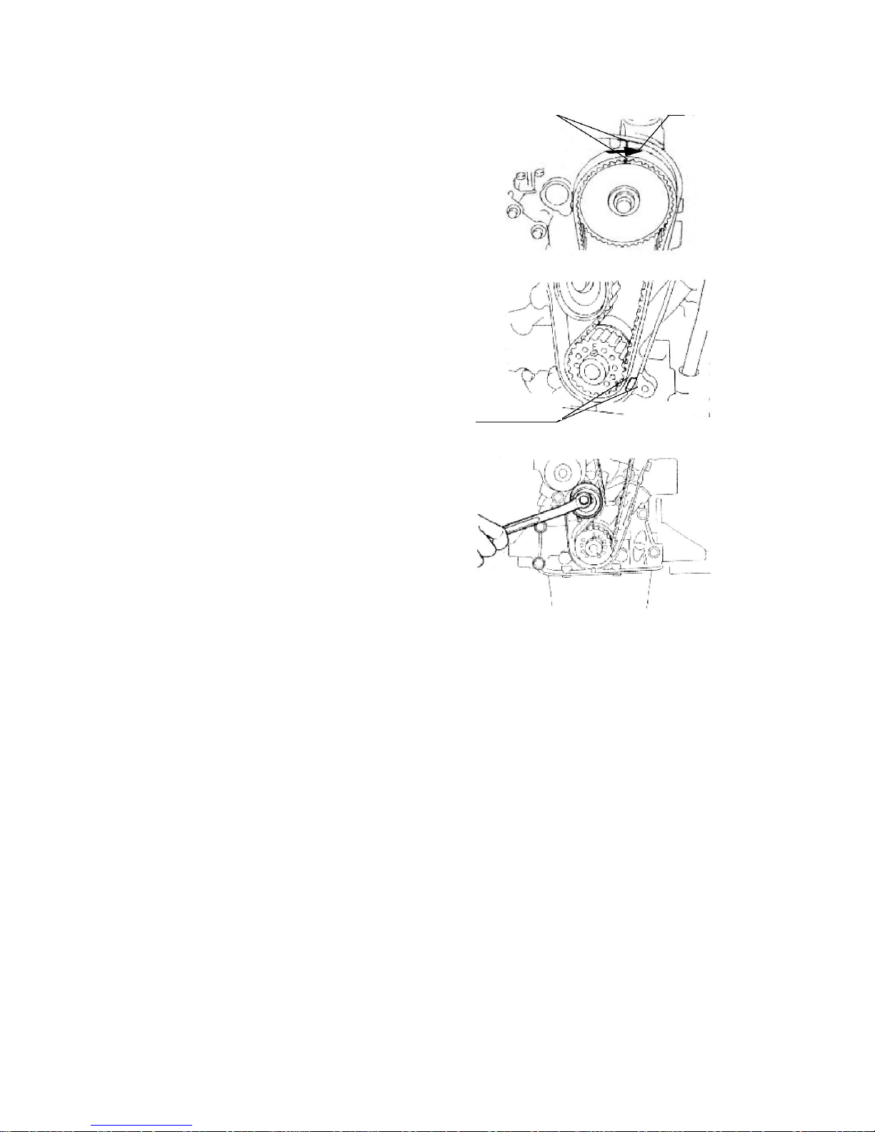
2.5. Remove the tensioner
2.5.1. Carry out the operation at the upper
thrust point of compression of the
first cylinder piston
2.5.2. After removing the timing cover cap,
turn the bolt and rotate the timing
gear clockwise with wrench, align
timing mark of camshaft timing gear
with the cam mark of camshaft
cover cap;
Attention: You can rotate the engine
clockwise only, after installing the pulley;
before removal, make a arrow mark on the
position of timing mark, assemble
according to original state.
2.5.3. Make sure that the crankshaft timing
pulley wheel mark is aligned with
the mark of the oil pump.
2.5.4. Remove the tensioner bolt, and take
off the tensioner
2.6. Remove the timing belt.
[Caution] It is absolutely not allowed to
use screw driver or some other
sharp-edged tools to remove the belt.
Attention: Pay attention to the following
points while using timing belt:
- Don’t bend the belt even at a small angle,
otherwise it will result in rope fracture
inside the belt.
- - Service life of belt is short, don’t pollute
the belt with grease and water.
- You have no choice but rotate
2.7. Remove the crankshaft timing gear
Timing mark
Page 69
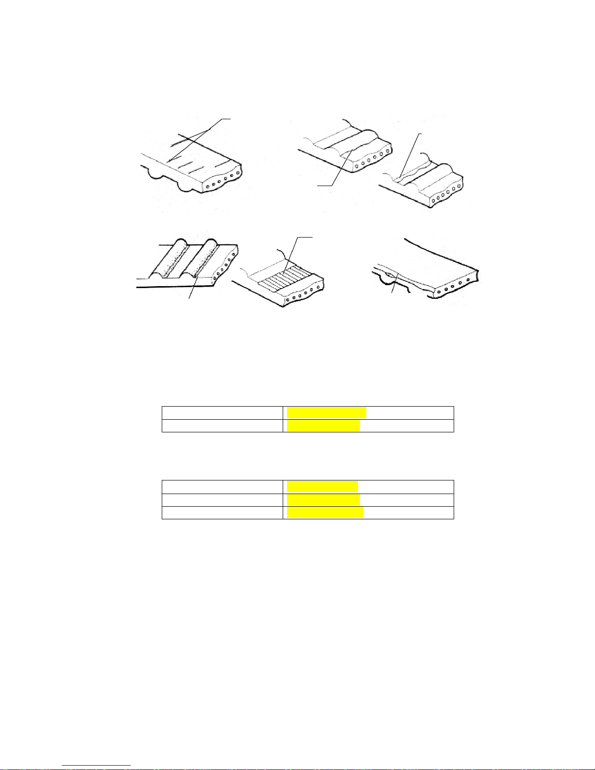
69
2.8. Make careful and detailed checks on the timing belt. Replace with new parts if any
of the conditions shown in the figure occurs.
2.8.1. Cracks on the backside rubber;
2.8.2. Cracks of teeth roots, cracks clearing off the fabric lining layer;
2.8.3. Tears and wears of fabric lining layer, missing rear teeth, broken teeth, etc.
2.8.4. Abnormal tears and wears on belt sides
2.8.5. Even if the damages on the outer appearance can not be confirmed, the belt
should be replaced under any of the following circumstances:
2.8.5.1. If the water in the water pump is leaked, which makes it necessary to refill the
water continuously;
2.8.5.2. There are much oil stains on the belt, the belt should be replaced for the rubber
will be damaged when it is expanded;
Specifications and model of the timing belt
Part number P 372-1007081BV
Belt wide 27.0 mm/1.06inch
Timing belt tensioner
Turn the belt tensioner supporting stand bolts to see if there is any abnormal sound.
Check to see if there are any damages on the contacting surface of the belt.
Specifications and model of the timing belt tensioner
Part number 372-1007081BV
Wide 27.0 mm/1.06inch
Outside diameter φ50mm/1.968 inch
Check to see if there are any damages on the outer appearance
Specifications and model of clockwise pulley
Chap
Chap
Tears and wears
Abnormal Tears and wears
MIS
Drop-off of belt core
Page 70

70
Model
EF
Item GL、ZL、GS、ZS
Diameter of camshaft
timing gear (mm/ inch)
φ110.7
+0.1
-0.2
/φ4.3582
+0.039
-0.078
Diameter of crankshaft
timing gear(mm/ inch)
φ54.65
+0.7
-0.13
/φ2.1516
+0.0275
-0.0051
Baffle of crankshaft timing gear
Check to see if there is any deformation
Standard size of crankshaft timing gear:
3. Installation
3.1. Installation of crankshaft timing gear
3.2. Installation of timing belt
3.2.1. On the upper thrust point of the first
cylinder Compression Place the
camshaft timing gear around the front end
of the air exhaust camshaft so as to make
the positioning groove on the gear be
aligned with the positioning pin on the end
surface of the camshaft. Then use screws
to fix the clockwise gear, with the torque of
100 ± 5N.m/73.7*3.68Ft-Lb.
3.2.2. Make sure that the punched mark
on the crankshaft clockwise pulley is
aligned with the mark of the oil
pump.
3.3. Install the tensioner
3.3.1. Adjust the tension of the timing belt As
shown in the figure, make the space
between the edge of the stretching
wheel and the water pump case arc
to be about 8mm/0.3149 inch;
Tighten the bolt of the stretching
wheel with a torque of 25 ±
3N.m/18.4±2.2Ft_Lb. Use a
screwdriver to swing the stretcher
toward the right.
Wide 28.6mm/1.125inch
Page 71
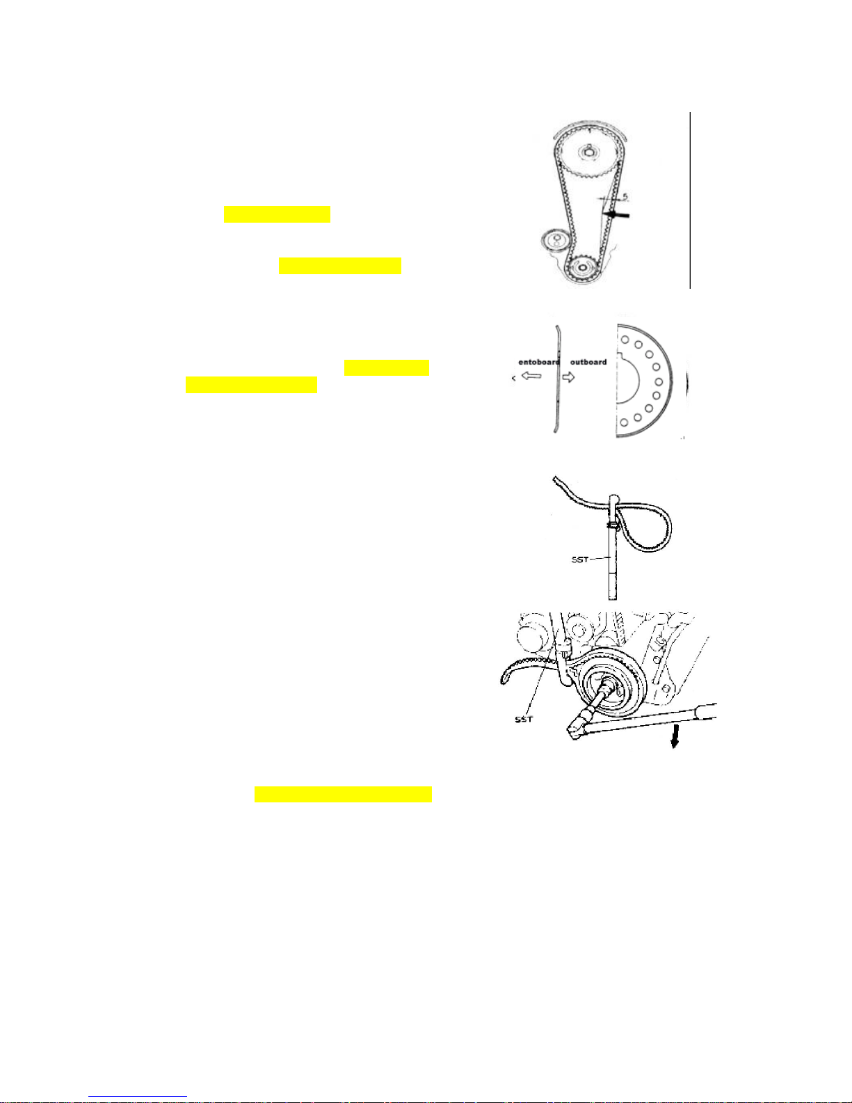
71
3.3.2. Turn the crankshaft for two circles
towards the engine rotating
direction, so that the camshaft
pulley and the crankshaft pulley
match the clockwise marks
respectively.
3.3.3. Use hands to press down for about
5 mm /0.1968 inch. The force for
pressing the clockwise belt is about:
[Reference] 20~30 N/4.5~6.7lbf
Notice: When the deflection of the timing
belt fails to meet the specifications, the key is to adjust
the above-mentioned stretcher fastening bolt by
widening he spacing. Tighten the S/A fixing bolt of the
stretcher with the specified torque of 25 ±
3N.m/5.62±0.67FT-Lb.
3.4. Install the baffle of the crankshaft-timing pulley
[Attention] Install the baffle towards the direction
shown in the right figure.
3.5. Install the tensional vibration damper
(use SST)
3.5.1. When there is not a flying wheel,
3.5.1.1. Fix a part of the crankshaft pulley.
3.5.1.2. Pay attention not to make the gear
belt moving, tighten the bolt
according to the specified
torque :98.0±10N.m/72±7.37Ft_Lb
Page 72
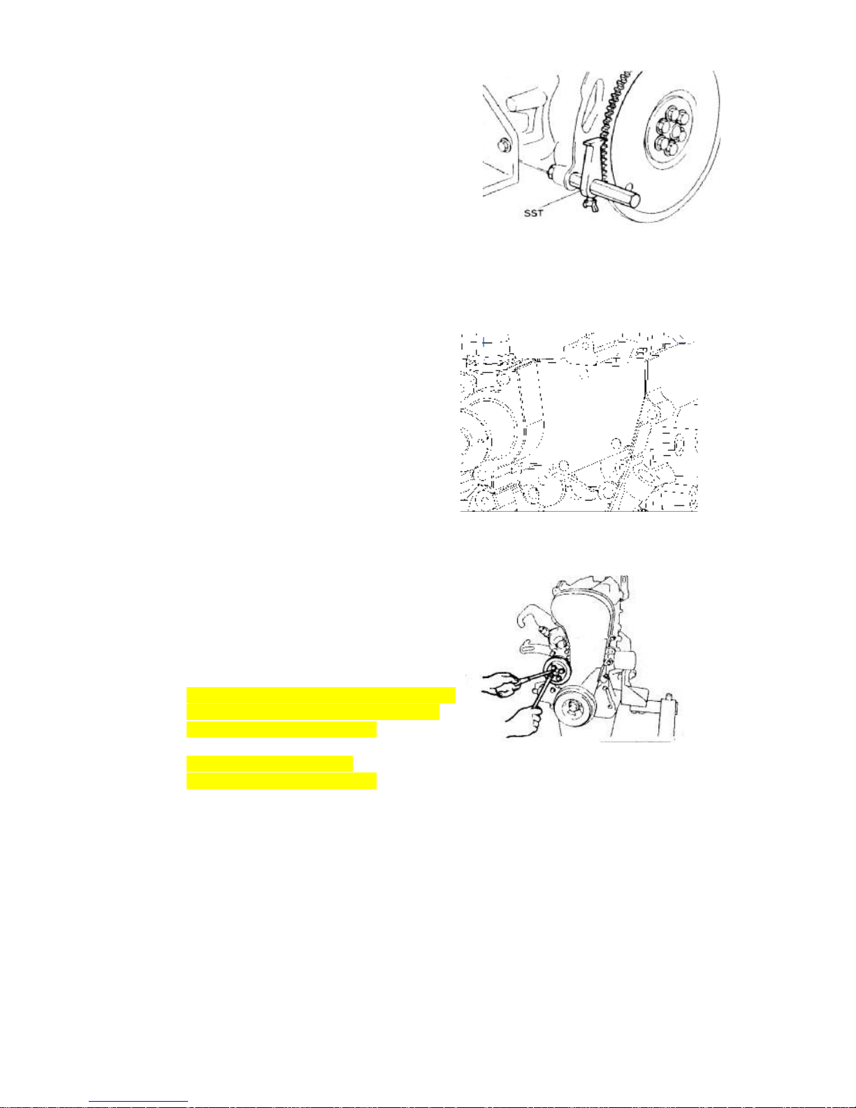
72
3.5.2. When there is a flying wheel,
3.5.2.1. Fix the flywheel to prevent the
tooth ring from turning
3.5.2.2. Then tighten bolt of tensional
vibration damper.
3.6. Install timing belt cover
Install seal strip in the position shown as
right figure. Install the position 1 and
position 2 before cylinder head assembly;
install position 3 before tighten water
pump.
Install the timing belt cover, screw the bolt
manually, and then tighten them with a tool.
Torque: 6±1N.m/4.42±0.73Ft-Lb.
3.7 Install water pump pulley
Torque: 6±1N.m/4.42±0.73Ft-Lb.
Page 73
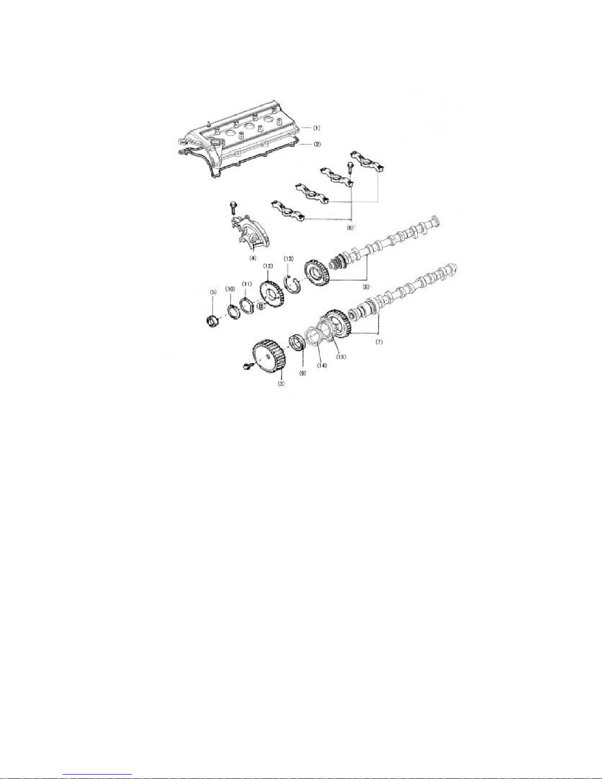
73
Camshaft
1. Configuration diagram
(1) Valve cage cover (2) Valve cage cover gasket (3) Camshaft timing pulley (4)
Camshaft cover (5) Circular plug (6) Camshaft bearing cap (7) Exhaust camshaft,(8)
Intake camshaft,(9) Oil seal(10) Spring retainer(11) Wave washer(12) Intake camshaft
sub-gear(13) Snap ring(14) Lock nut(15) Flange
※:Non-reusable part
Unit: N*m/kg*cm/Ft_Lb
Page 74

74
2. Removal
2.1. 1) Cover-valve chamber
2) Disassembly order of Cover-valve
chamber
2.2. Dismount the timing belt sprocket
with a special tool.
Attention: Manufacture a special tool
according the right figure
A special tool is needed to prevent the
camshaft from rotate,
See figure below.
2.3. Removal of camshaft bearing cover
2.3.1. Align the marks on the camshaft
gears as shown in the right figure.
Timing mark
Air outlet camshaft gear
Air inlet camshaft gear
Page 75
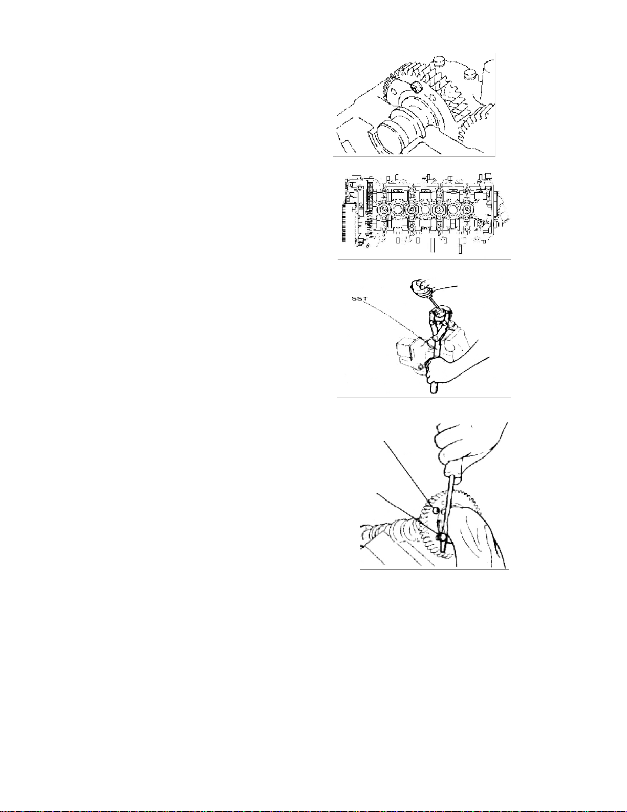
75
2.3.2. Use bolt to position the master and
slave gears on the air inlet camshaft,
as shown in the right figure.
Attention In order to eliminate the radial
force, keep the camshaft in the leveled
position before dismounting it (to avoid
possible damages caused by excessive
radial forces)
2.4. Remove bolts according the right
figure, remove camshaft bearing
cover
2.5. Remove the spark plug
2.6. Remove the camshaft slave gear.
2.6.1. Use the special tool as shown in the
right figure.
Clip the camshaft tightly, and turn the gear,
to keep the bite state of master and slave
gear; remove the fixing bolts of slave gear.
Attention: Do not damage the surface of
the camshaft.
2.6.2. Don’t Use the special tool
(1). Screw bolt M6 on the camshaft slave
gear as the right figure show
(2). Rotate the gear with a screwdriver;
remove the bolt fixing slave gear
Attention: Do not damage the surface of
the camshaft.
(3). Remove retainer for shaft with
tensionor, remove waveform washer,
driver ring and saddle flip washer.
Screw
Bolt
Fixer
Page 76
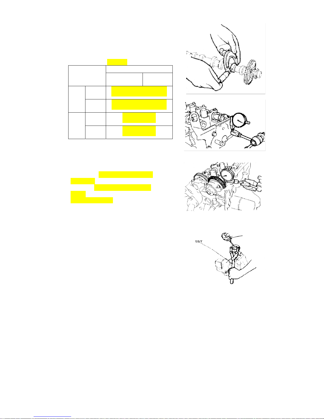
76
2.7. Camshaft
2.7.1. Use the caliper to measure the
height of the camshaft. If it is below
the specified limits, make proper
replacement.
Camshaft Unit:mm /inch
Model
EF
Item ZL、RL
GL、GS、
ZS
Stan
dard
IN
φ23.0
-0.02
-0.033
/φ0.9055
-0.0008
-0.0013
EX
φ23.0
-0.02
-0.033
/φ0.9055
-0.0008
-0.0013
Limit
IN
φ22.9/φ0.9016
EX
φ22.9/φ0.9016
2.7.2. Checks on camshaft axial clearance
(1)、When the axial spacing is measured
with a clipper to be larger than the
benchmark value, the camshaft is to be
replaced. The air inlet camshaft axial
clearance is 0.1~0.170mm/0.0039~
0.0067inch。The air exhaust camshaft axial
spacing is 0.1 ~0.173mm/0.0039~
0.0068 inch。Limits for operation:
0.18mm/0.007 inch.
2.7.3. Checks on camshaft meshing
clearance
(1). Put camshaft into cylinder head
(2). Make sure the front mark on bearing
cover and shaft number is ok, and then
tighten bolt.
(3). Fix air inlet camshaft, and then
measure the clearance with dial indicator.
Attention: measure 4 points around gear
·use a special tool to rotate air inlet
camshaft.
·under the condition that the mark on
drive-gear match the mark on driven-gear
3. Installations
3.1. When using a special tool
3.1.1. Fix the two φ6 holes of the camshaft gear S/A.
3.1.2. Turn the slave gear to the right, match the mark
Page 77

77
hole on the slave gear with the mark on the
master gear, or align the marks on the slave
gear with the mark on the master gear; then fix
the slave gear with bolt.(Thread: M5; pitch: 0.8)
3.2. When no using a special tool
Screw bolt m6 as the right figure, and then
insert a screwdriver between the bolt m6
and camshaft, and rotate driven-gear right
to match the mark on both of gears, or
keep the gear-top of 2 gears consistent,
and then fix driven-gear with bolt(M5×0.8).
Attention: Do not damage the surface of
the camshaft.
3.3. Installation of the camshaft
Attention: Size of the axial clearance of
the camshaft
3.3.1. Smear lubricating oil at the
camshaft gear section and the
cylinder cover axial diameter
section.
3.3.2. Fix the camshaft slave gear by
roughly adjusting on the cylinder
cover.
3.3.3. Install camshaft, the timing mark
must be aligned shown as the right
figure.
3.3.4. Smear lubricating oil on the
camshaft assembly, the gears and
the cylinder head axial diameter
section.
3.4. Tighten the camshaft-bearing cap
shown as right figure.
3.5. Remove the bolt for fixing the slave
gear of the camshaft assembly.
Fixer
Bolt
Timing mark
Air outlet camshaft gear Air inlet camshaft gear
Fixer
Page 78

78
3.6. Installation of camshaft head cap
Smear the fluid sealant on the camshaft
head cap section (With oil groove) shown
as the right figure.
3.6.1. Tighten the bolts according to the
sequences shown as the right figure
with the specified torques.
3.6.2. After smearing oil in the plug cap
hole and assembling surface of the
plug, use SST to press the plug lid
Attention: Install the plug lid shown as the
right illustration. Keep unbiased with
cylinder head end surface after
pressing.1±1mm/0.0394±0.0394inch。
3.7. Smear engine oil on the oil seal
installation port of cylinder head,
camshaft oil seal edge of blade and
outside ring, use M10 bolt (length
50-60 mm/ 1.9685-2.3622inch) and
SST press the cylinder, lower
1mm/0.0394 inch than the end
surface of the cylinder4 head.
Attention ·Under the condition of use the
oil seal repeatedly, press here with engine
oil adhesive agent - The oil seal should not
be pressed inclining to one side.
3.8. Installation of the timing gear of
camshaft After smearing the fluid
sealant, use SST to prevent rotating,
tighten the timing gear bolt of
camshaft according to regulated
torque of 100±5N.M/73.7±3.6Ft_Lb.
Sealing line
Outside
Page 79
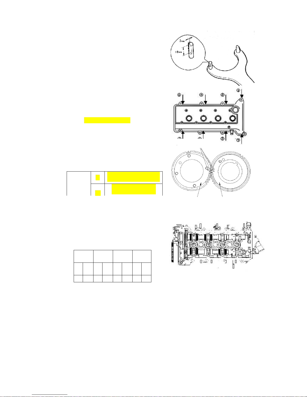
79
Attention: process the special tool
according the right figure.
3.9. Installation of cylinder head gasket
3.9.1. Clean the the used cylinder head
gasket
3.9.2. Put new one into the groove on the
timing-belt cover accurately
3.9.3. Cover the cylinder head with
cylinder head cover; tighten the
bolts according the right figure.
Torque: 6±1N.m /6±0.7Ft_Lb.
4. Routine check
4.1. Standard of valve clearance:
4.2. Align the timing marks on the
drive-gear and driven-gear.
4.3. Use a plug gauge to measure the
clearance according the right figure
First
cylinder
Second
cylinder
Third
cylinder
Fourth
cylinder
I
N
EX
I
N
EX
I
N
EX
IN E
X
O O O — — O — —
valve
clearance
IN
0.18±0.05mm/0.007±0.002
EX
0.25±0.05mm/0.0098±
Timing mark
Air outlet camshaft gear Air inlet camshaft gear
Page 80
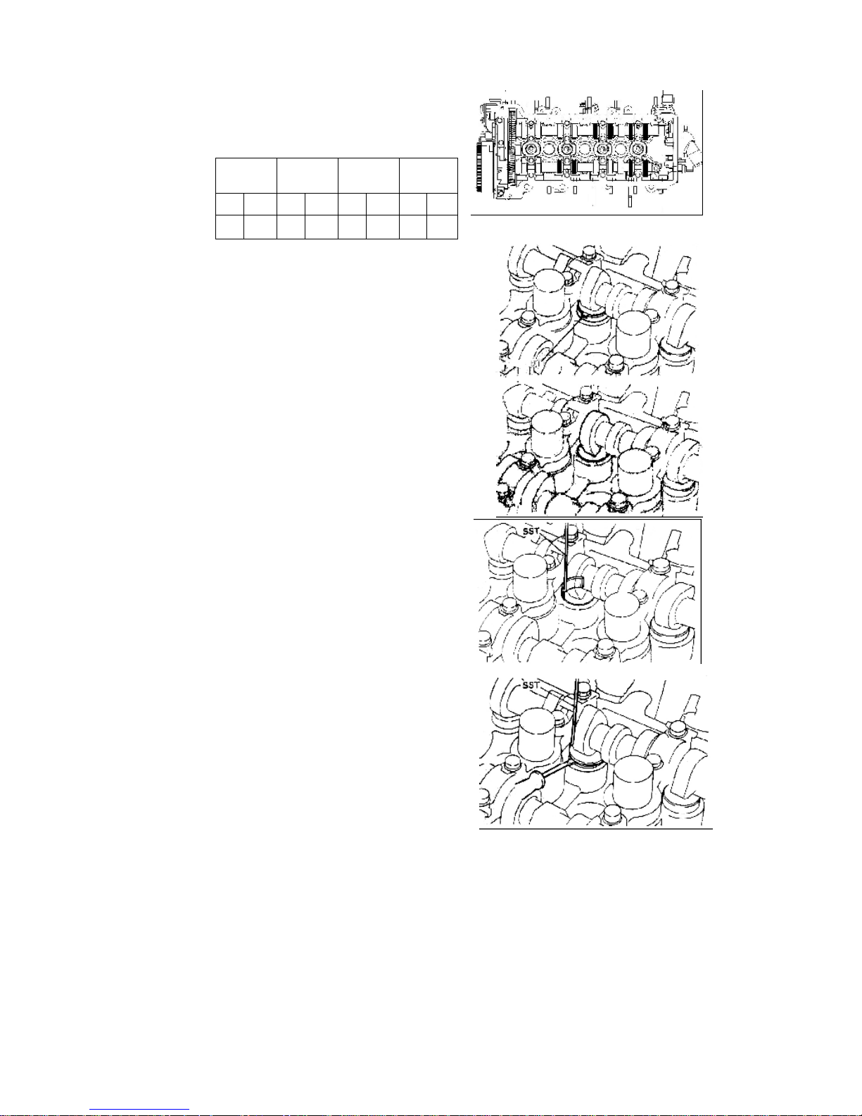
80
4.4. Rotate camshaft a round, keep the
position as the right figure, measure
the clearance again.
If exceed the standard of valve clearance,
replace a adjusting washer to get a proper
clearance
Attention: record the position where valve
clearance exceed the standard
and the result
4.4.1. Rotate camshaft to make the
cam-top (valve clearance exceed
the standard) upwards, and gap of
valve lifter towards inside.
4.4.2. Rotate camshaft and the cam press
valve lifter down.
4.4.3. Load the special tool at the top of
the valve lifter around the valve lifter,
and then rotate camshaft to make
the cam-top upwards, press valve
lifter down with a special tool, and
hold it.
4.4.3.1. Move the adjusting washer out
with a screwdriver, and then
remove the washer with a magnet
iron wire from inside.
First
cylinder
Second
cylinder
Third
cylinder
Fourth
cylinder
IN EX IN EX IN EX IN EX
— — — O O — O O
Page 81

81
4.4.3.2. Use a caliper to measure and
adjust the thickness of the
separation cushion.
4.4.3.3. Select proper separation cushion
on the basis of the throttle
thrusting rod benchmark values.
(1). IN
Selected cushion thickness = removed
cushion thickness + (measured throttle
spacing – 0.18mm/0.007inch)
(2). EX
Selected cushion thickness = removed
cushion thickness +(measured throttle
spacing –0.25mm/0.0098inch)
[Reference] there are 32 kinds of shim’s
thickness Shown as the illustration
(mm/inch)
4.4.3.4. Use the selected adjusting gasket
to adjust the throttle clearance.
Attention Install the feeler with the
identification mark facing downwards.
4.4.3.5. Rotate camshaft to make cam-top
downwards, and the throttle to be
pressed down, and then take
special tool out
4.4.3.6. Rotate camshaft 2-3 round, and
then recheck the valve clearance,
if valve clearance can’t get to the
standard, repeat 4.1-4.4 to adjust
the valve clearance.
2.18/0.0858 2.4/0.0944 2.62/0.1031
2.2/0.0866 2.42/0.0952 2.64/0.1039
2.22/0.0874 2.44/0.0960 2.66/0.1047
2.24/0.0881 2.46/0.0968 2.68/0.1055
2.26/0.0889 2.48/0.0976 2.7/0.1062
2.28/0.0897 2.5/0.0984 2.72/0.1070
2.3/0.0905 2.52/0.0992 2.74/0.1078
2.36/0.0929 2.58/0.1015 2.8/0.1102
2.32/0.0913 2.54/0.1 2.76/0.1086
2.38/0.0937 2.6/0.1023
Underside
Page 82

82
Cylinder head
1. Configuration diagram
(1) Spark plug20±1Nm(2) Cylinder head(3) Weather seal I(4) Cylinder head
gasket(5) Adjust shim(6) Valve lifter(7) Keeper(8) Valve spring seat(9) Valve
spring(10) Intake valve(11) Exhaust valve(12) Valve oil seal(13) Valve seat
(14) Valve guide
Page 83
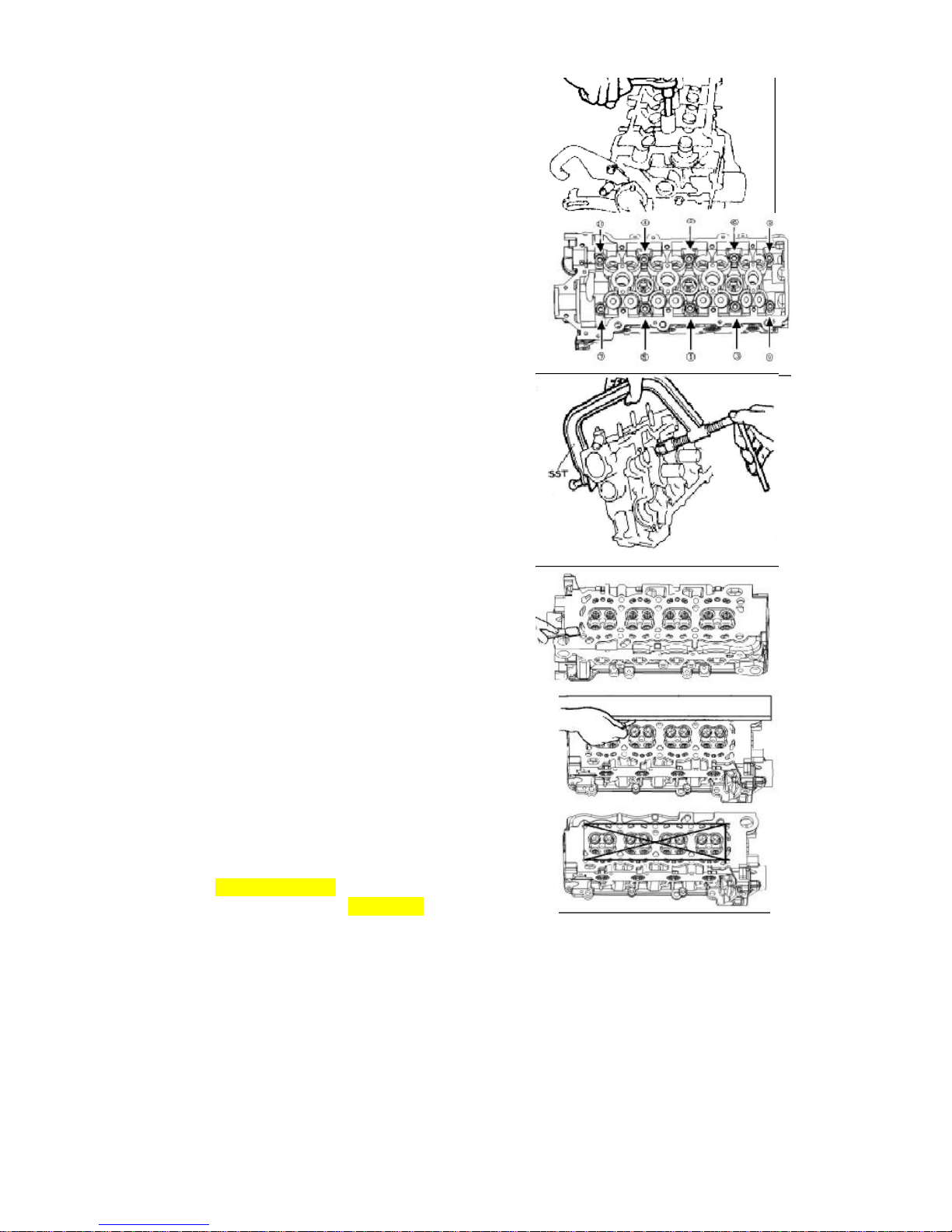
83
2. Dismounting
2.1. Removal of spark plug
2.2. There are 8 cylinder cover bolts. In
the process of removing the cylinder,
please follow the sequences shown
as the right illustration, loosen the
bolts one by one evenly and gently.。
2.3. Removal of the cylinder dustproof
sealing and cylinder cover base.
Attention The cylinder cushion cannot be
used repeatedly.
2.4. Removal of throttle adjusting
separation cushion and valve
thrusting rod
2.5. Use special tools to remove the
valve spring locking block, throttle
spring stand, valve spring, IN valve
and EX valve
2.6. Removal of valve oil seal and valve
spring washer
2.7. Clearing
(1). The accumulated carbon residue
covered on the valve must be cleared.
(1). Use scraper to clear the cylinder
cover, the air inlet and exhaust branching
pipe surfaces and bottoms
Attention
Do not damage the cylinder cover surface
by scraping
during the process of clearing.
Do not drop filth into the air inlet and the
water channel.
3. Routine checks
3.1. Cylinder cover
Use the straight knife sharp edge ruler to
measure the levelness at various points as
shown in the figure. Cylinder cover
0.10mm/0.0039inch Air inlet branching
pipe surface 0.10 mm/0.0039inch
Page 84
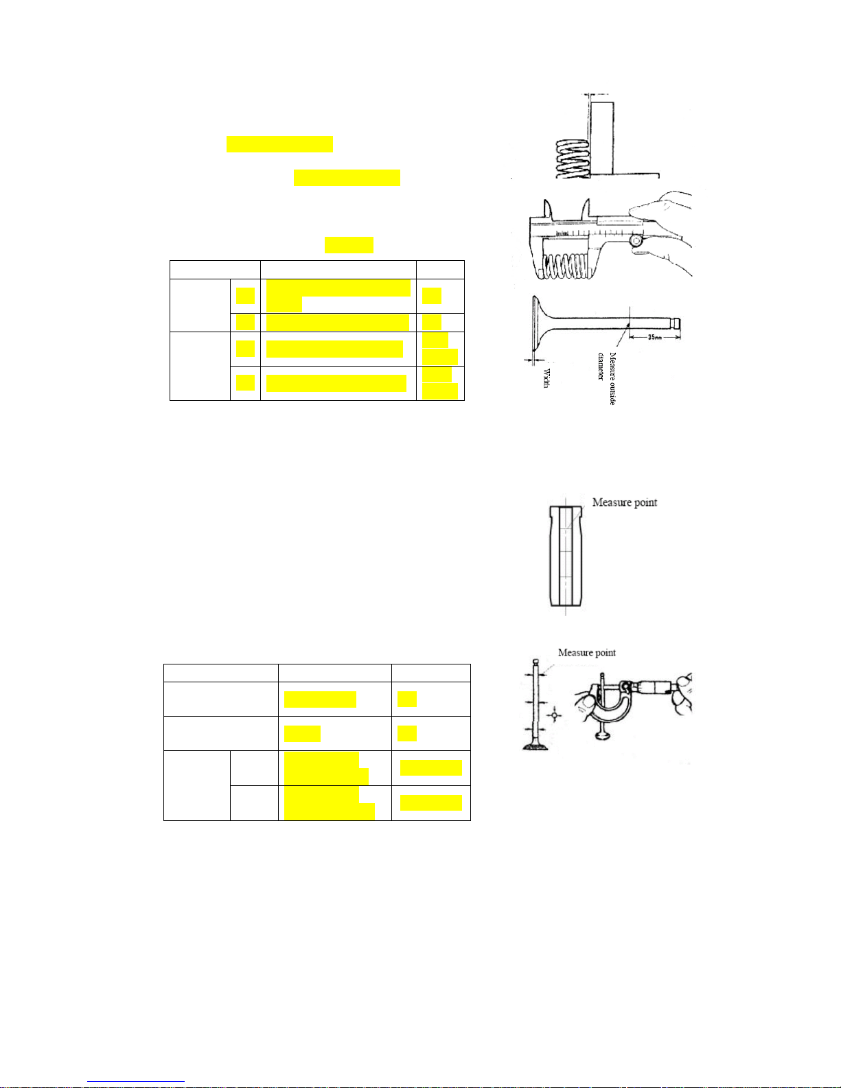
84
3.2. Valve spring
3.2.1. Use a square ruler to measure the right
angle of the valve spring. Replace the
spring if it fails to meet the specifications.
[Limit] 1.2mm/0.0472inch
3.2.2. Measure the free state of spring
[Benchmark value] 37mm/1.4567 inch
3.3. Routine checks on throttles
3.3.1. Check to see if there are some
deformations, obvious tears and wears
Check list on valve Unit: mm/inch
3.3.2. Checks on the clearance between
the throttle guiding pipe and throttle
thrusting rod .
3.3.2.1. Use a dial gauge to measure the
inner diameter of the
throttle-guiding pipe, and use a
caliper to measure the outer
diameter.
3.3.2.2. Work out the differences of the
measured values. If it is above the
specified limits, the throttle or the
guiding pipe must be replaced.
Attention The measurement points are
shown as the figure. Work out the
clearance of the final torn and worn section
item
standard limit
wide
IN
0.85 ~ 1.41/ 0.0335 ~
0.0555
—
EX 1.07~1.36 /0.042~0.0535 —
Width of
valve top
IN 1.0±0.2 /0.0394±0.0078
0.75/
0.0295
EX 1.0±0.2 //0.0394±0.0078
0.75/
0.0295
item standard limit
Valve guide Inside
diameter(mm/inch)
φ5.0 /0.1968 —
Valve stem outside
diameter (mm/inch)
φ5.0 /0.1968 —
Spacing
(mm/inch)
IN
0.056~0.020/
0.0022~0.0008
0.07/0.0027
EX
0.066~0.030/
0.0026~0.0012
0.08/0.0031
Page 85
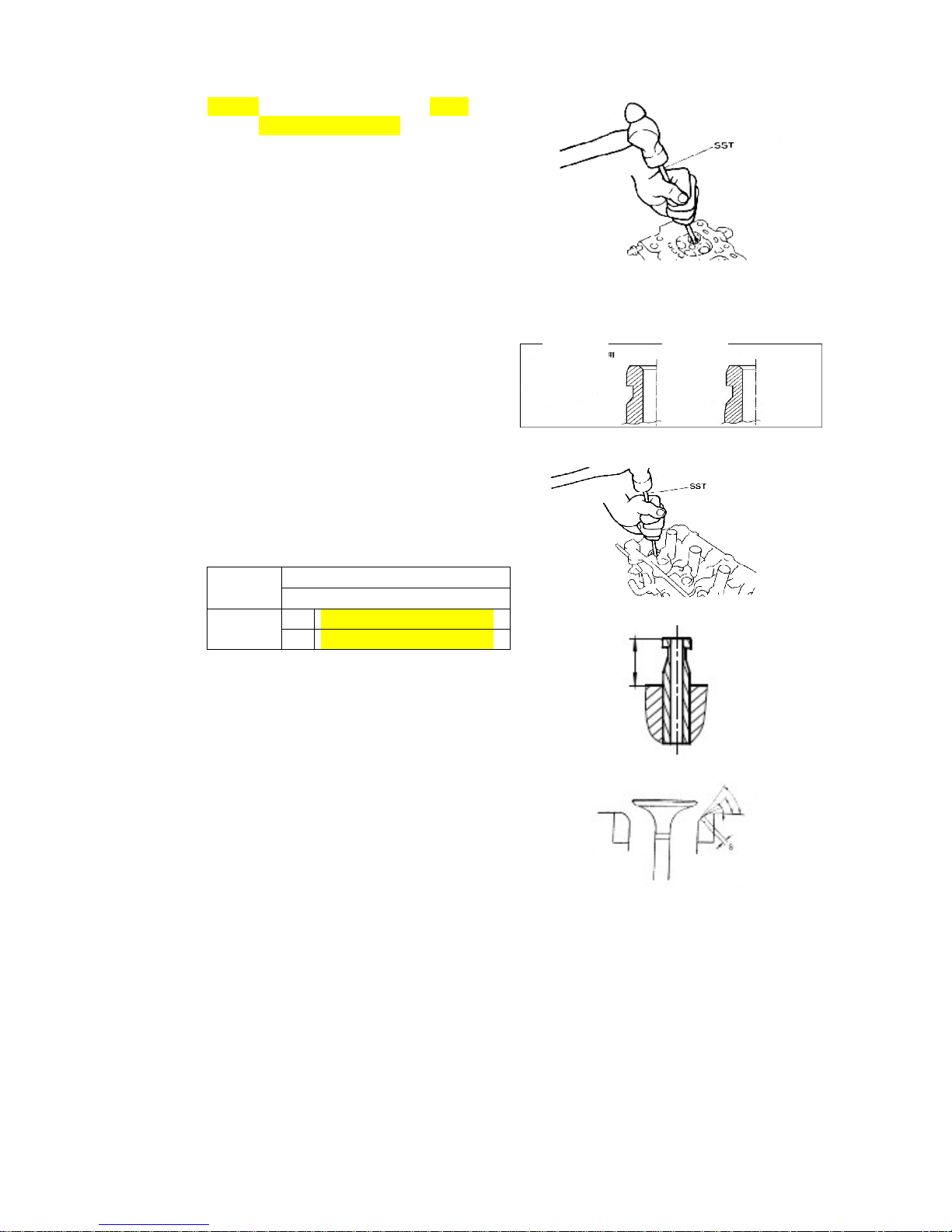
85
3.3.3. Replacement of valve guide
3.3.3.1. Heat the cylinder cover to 176~
212℉ with hot water.
3.3.3.2. Use special tools to drive in the
valve-guiding pipe to the position
as shown in the right figure from
the side of the combustion
chamber.
Attention The removed guiding pipe
cannot be used repeatedly. The air intake
and exhaust valve guiding pipes should
not be mixed up in installation.
3.3.3.3. Use special tools to drive in the
new valve-guiding pipe to the
position as shown in the right
figure.
Attention In the process of driving in the
guiding pipe into the cylinder cover, the
operation should be carried out slowly until
the pipe gets to the proper position. No
excessive driving should be exerted. Pay
attention to the specifications in the
operation. Driving in depth of throttle
guiding pipe
3.3.3.4. Use reamer to grind the inner
diameter to achieve the standard
value of the clearing.
3.3.4. Valve mating surface
3.3.4.1. Smear thin layer of red lead
powder on the valve-mating
surface. Do not turn the valve, and
gently drive it in. Check the mating
condition and the width of mating
line.
model EF
item GL,ZL,RL,GS,ZS
Height
(mm/inch)
IN 13.71±0.25/0.5398±0.0098
EX 12.11±0.25/0.4768±0.0098
For IN
For EX
Page 86
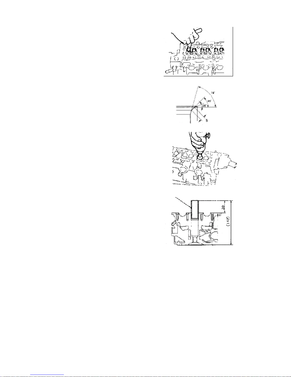
86
3.3.4.2. Correction of valve base stand ring
Attention Signs of breaking or cracking
should not appear on the correction
surface. Take it out slowly after the
correction is completed.
3.3.4.3. Use a 45 degree cone as the
mating benchmark value.
3.3.4.4. Check the mating position of the
throttle. If it is in the center of the
valve, the position is the best one.
If not, proper corrections have to
be made.
3.3.4.5. Make conic cutting at the center of
the mating position with 70
degrees toward inwards and 30
degrees outwards.
3.3.4.6. Use polishing agent to grind and
polish the throttle sealing.
3.4. Assemble of cylinder head
3.4.1. Cylinder head
Pay attention to the following instructions
in the process of assembling for the other
accessories on the cylinder cover.
3.4.2. Spark plug insulator 1 Put the spark
plug insulator in the corresponding
hole
on the cylinder head with special use
auxiliary tools, smear fluid sealant before
pressing, pressing height is shown as the
illustration:
Attention· Pay attention that the vertical
degree of its pressing depth and the
cylinder head top surface;
· The insulator should not be deformed
while being pressed; otherwise, it is easy
for the valve chamber cover cap to lea
Spark plug insulator
Page 87
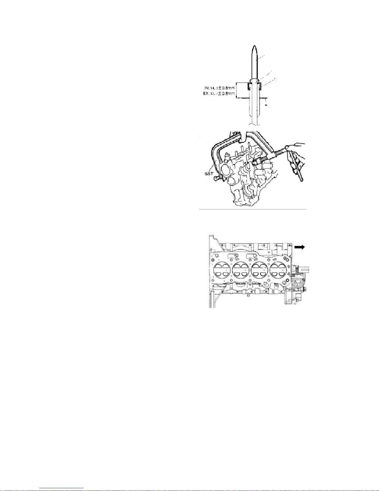
87
3.4.3. Installation
3.4.3.1. Installation of valve spring
washer and valve oil sealing
3.4.3.1.1. Cover auxiliary tools on the
valve rod head, smear
oil on the outer circle of the auxiliary
roundness and inside of new valve oil
seal, install it on the illustrated position,
pull out the auxiliary tools of valve oil
seal.
[Reference] Insert the oil sealing up to
the dimension as shown in the right
figure.
3.4.3.2. Installation of IN and EX
3.4.3.2.1. Assembling of valve springs
Attention It is for you to distinguish the
different suppliers by means of
paintings on the valve spring, valve
spring of same engine should have the
same identification paint marking.
3.4.3.3. Install the locking blocks for
the valve spring stands.
Warning
·Protective eye glasses must be worn
in the process of this operation to
protect the eyes.
·Beware of the flying spring and other
objects
Upon completion of the installation of
the throttle springs and throttle spring
stands, use special tools to install the
locking blocks for the throttle spring
stands.
3.4.3.4. Installation of the throttle
thrusting rod and throttle
spacing by adjusting the
separation cushions
3.4.3.5. Install the cylinder cover base,
make identification of the
marks for the front and rear
directions.
Sub stool
Valve
Oil sealing
Spring bottom plate
Page 88
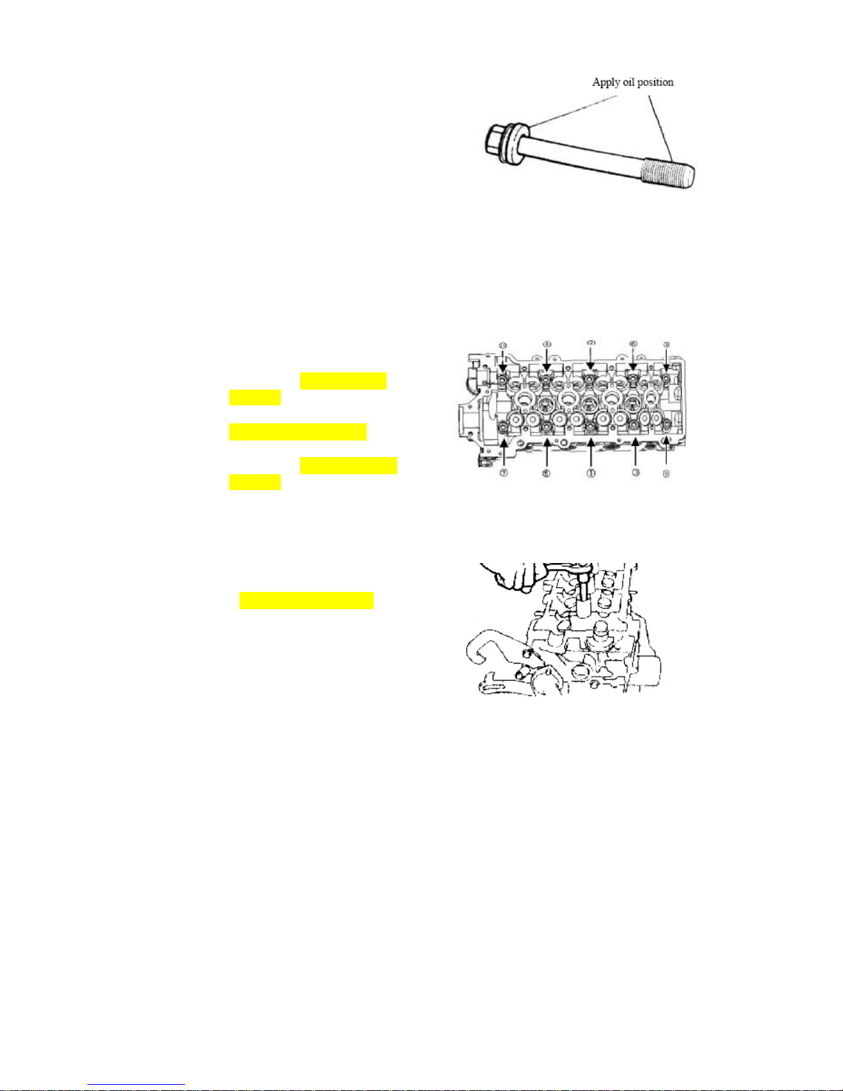
88
3.4.4. Assembling of dustproof sealing
strip and cylinder cover
3.4.4.1. Apply lubricating oil at the threads
and grooves of the bolts.
3.4.4.2. The tightening of the cylinder bolts
should follow the sequence as
shown in the right figure. The
tightening is to be carried out in
2—3 operations till the torque
meets the specifications. The
torque for the first tightening
operation is 30±2N.m /22±
1.5Ft_Lb; the torque for the
second tightening operation is
50±3N.m /36±2.2Ft_Lb; And the
torque for the third tightening
operation is 70±3.5 Nm /51±
2.5Ft_Lb.
3.4.4.3. Installation of the spark plug
[Torque] 20±1Nm /14±0.7Ft_Lb
Attention: The tools should be placed
vertically, so as not to make the spark plug
insulator become deformed, otherwise it is
easy to leak oil.
Page 89
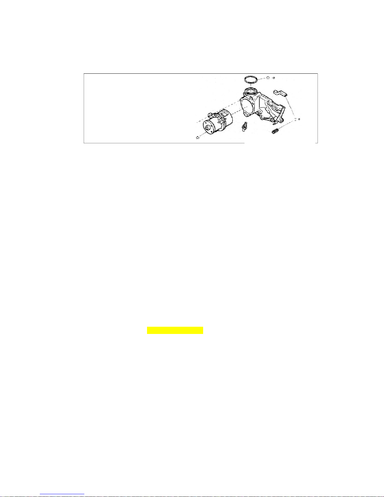
89
Water pump
1. Configuration diagram (the dismounting and assembling of the cylinder body
should be done in the following procedures)
1“O” ring, non-reusable2 Oil pump body3 Weather seal
2. Dismounting
2.1. Dismounting and removal of O-shaped ring
Attention: These rings are not reusable.
2.2. Removing the three bolts and dismount the water pump principal body.
2.3. Removal of the dustproof sealing stripe
3. Clearing
3.1. Clearing of the mating surface of the water pump
4. Routine checks
4.1. Check to see if there are any deformation or damages
4.2. Use a hand wrench to see if the turning is OK, and if it is smoothly lubricated?
5. Installation
5.1. Install the dustproof sealing stripes
5.2. Install the water pump principal body
Tighten with a torque of 25±1.5N*m/18±1Ft-lb
5.3. Install the new O-rings
※:Non-reusable part
Unit: N*m/kg*cm/Ft_Lb
Page 90

90
Oil pump
1. Configuration diagram (The dismounting and installation of the lubricating oil pump
should be carried out according to the following procedures).
○
1 Oil pan,tighten bolt:8±2 Nm/5.9±1.47Lb_Ft ② Oil strainer③ Oil collector
gasket④ Oil pump⑤ Oil pump gasket⑥ Rear oil seal bracket
2. Dismounting
2.1. The engine being turned upside down on
the dismounting frame, take off the bolts.
Remove the oil pan from the cylinder
body.
Attention: Do not make the oil pan flange
section to be deformed.
Non-reusable part
Page 91
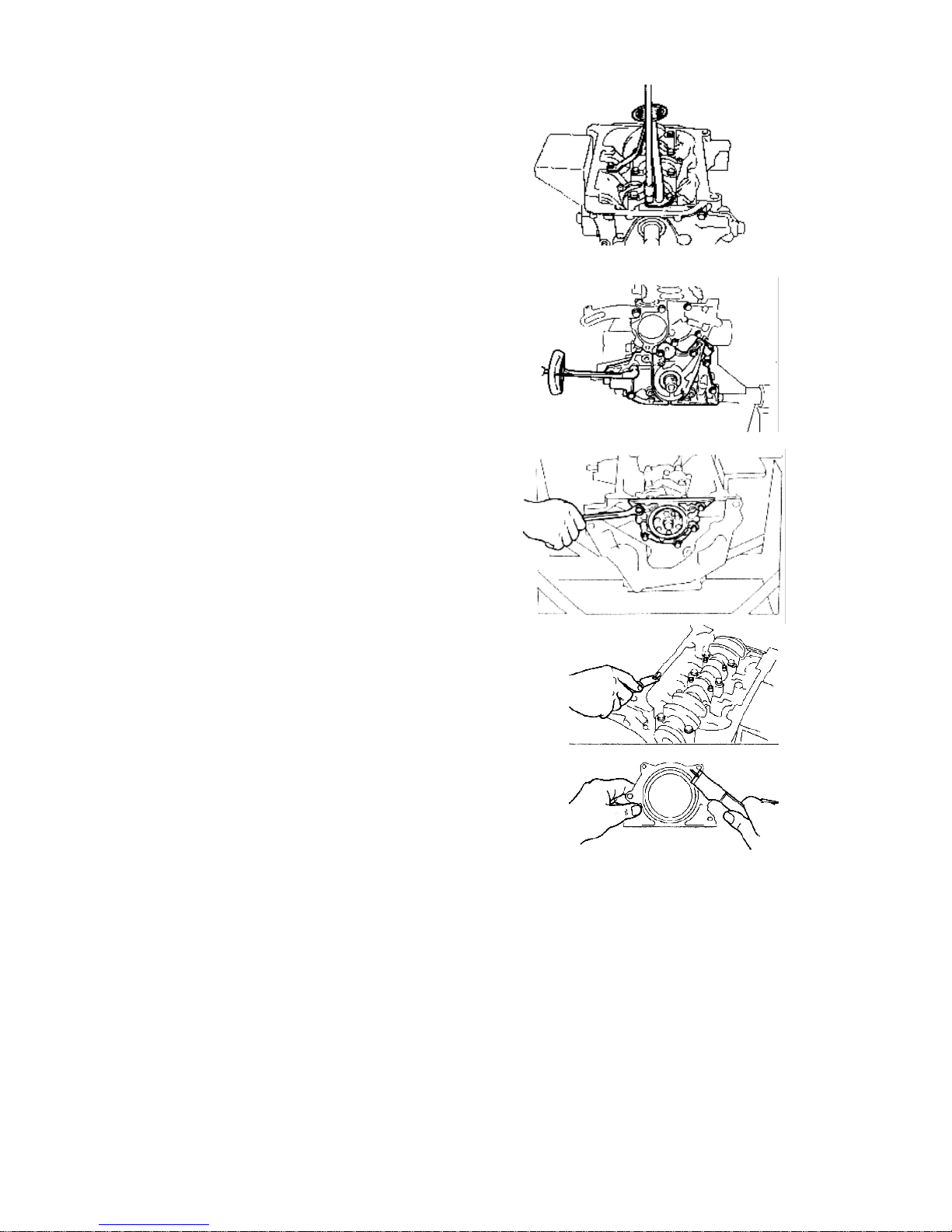
91
2.2. Remove the oil collecting filter and its
flange
Attention The filter flange is not reusable.
2.3. Dismount the oil pump assembly and
oil pump cushion
2.4. Dismounting of oil seal stand
3. Clearing
3.1. For the mating surfaces of the oil
bottom case, oil pump and oil seal
stands, for the mating surfaces of the
rear oil seal stand and oil pump
scraper and chipping chisel or some
other tools may be used to clear the
used ones.
Attention Do not drop the residues into
the cylinder body.
Page 92
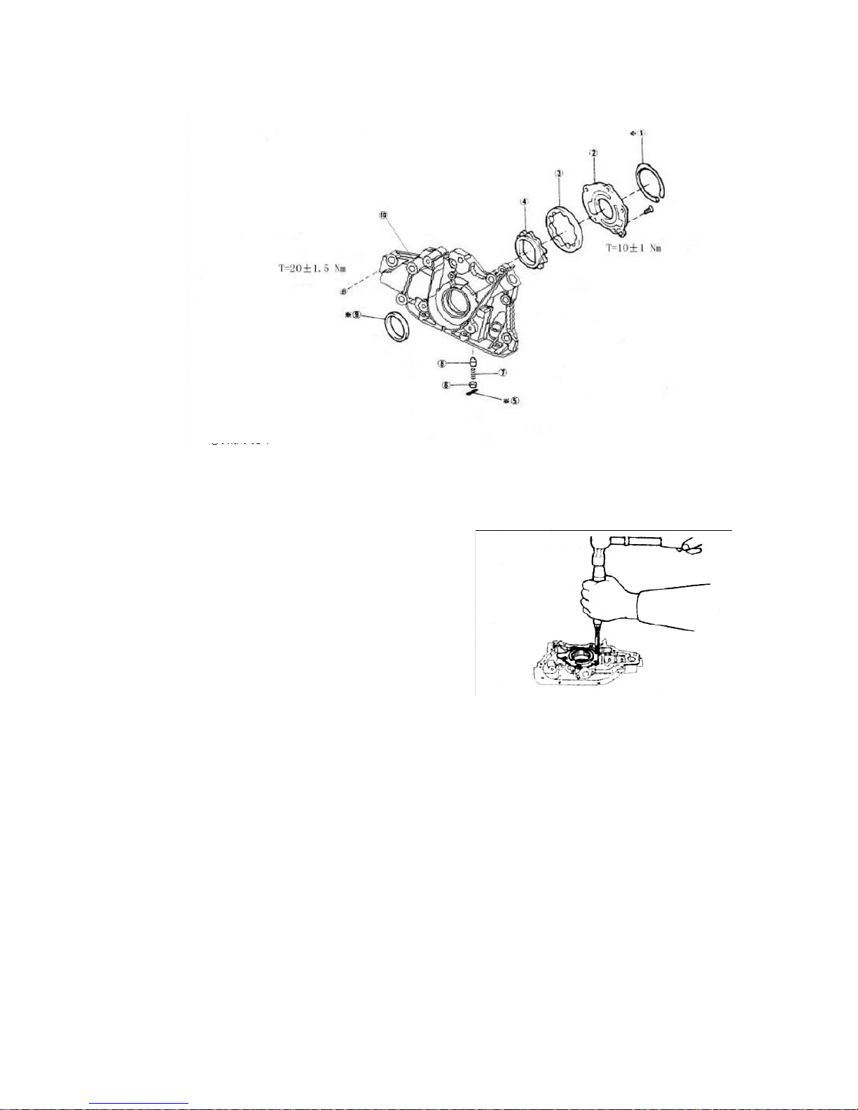
92
4. Disintegration and assembling of oil pump
4.1. Configuration diagram
1 Weather seal 2 Oil pump cover plate3 Driven rotor4 Drive rotor5 Split pin6 Relief valve
spring seat7 Relief valve spring8 Relief valve9 Crankshaft front oil sealing10 Oil pump
body
4.2. Disintegration
4.2.1. Weather seal
Attention The weather seal are not
reusable.
4.2.2. Remove the oil pump cover
Attention: The bolt is assembled with glue;
loosen it with screw driver according to the
illustrations
4.2.3. Remove the driven and drive rotor
of the oil pump
※:Non-reusable part
Unit: N*m/kg*cm/Ft-lb
Page 93
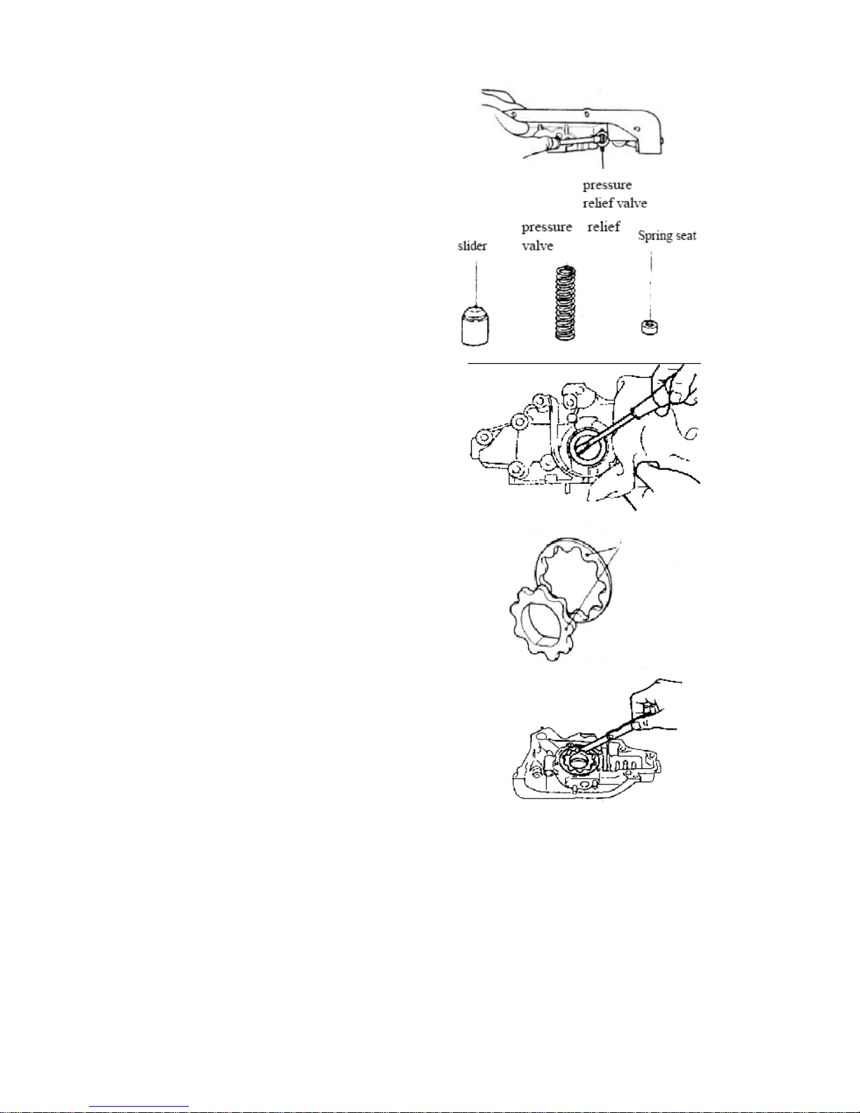
93
4.2.4. Take off the split pin
Attention The split pins are not reusable.
Attention: Pay attention not to make the
spring and spring seat sending forth and
ropping suddenly, while taking off the open
pins.
4.2.5. Removal of the oil pump pressure
relief valve spring stand, spiral
spring, oil pump pressure relief
valve
4.2.6. Removal of the front oil seal of the
crankshaft
Attention The removed oil seals are not
reusable.
4.3. Routine checks
4.3.1. Checks on lubricating oil pump
spacing
4.3.1.1. Follow the mark on the interior and
exterior gears of the oil pump to
place it into the lubricating oil
pump body on the cylinder body.
4.3.1.2. Use a feeler to measure the
clearance between the interior gear and
the exterior gear
[Benchmark]
0.05-0.18mm/0.002-0.007inch(average of
9 points)
[Limit] 0.35 mm/0.0137inch
MARK
Page 94
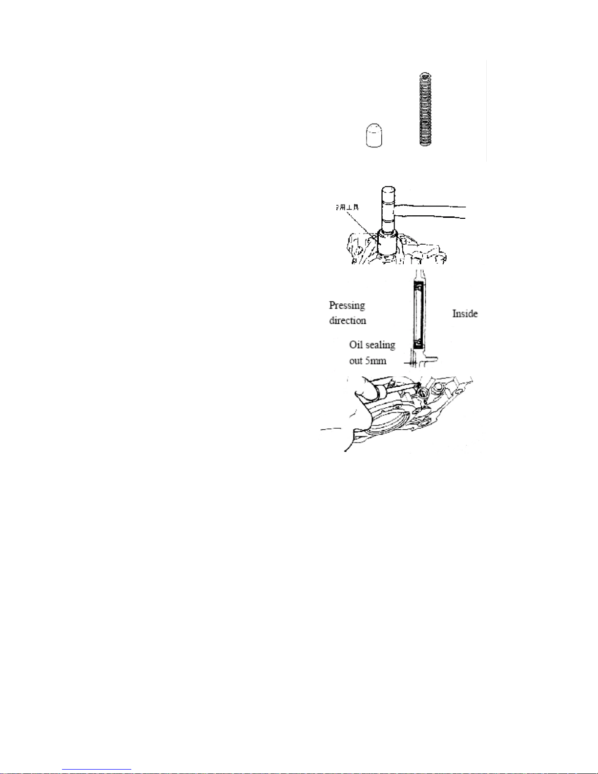
94
4.3.1.3. Use a feeler to measure the
clearance between the rotator and
the pump body
[Benchmark]
0.10-0.181mm/0.004-0.0071
[Limit] 0.25mm/0.0098inch
4.3.2. Routine checks on the pressure
relief valve
4.3.2.1. Remove the pressure relief valve,
there should be no visible tears,
wears and scrapes on the
pressure relief valve
4.4. Installation
4.4.1. After smearing lubricating oil on the
lips of the new T-shaped oil seals,
use SST to make the assembly.
Attention
·Use new oil seal..
·The exposed part of the outer edge of the
oil seal after being pressed in should be
less than 0.5mm/0.0197inch.
4.4.2. Assembling of the oil pump
pressure relief valve and split pins
Attention The split pins are not reusable.
Page 95
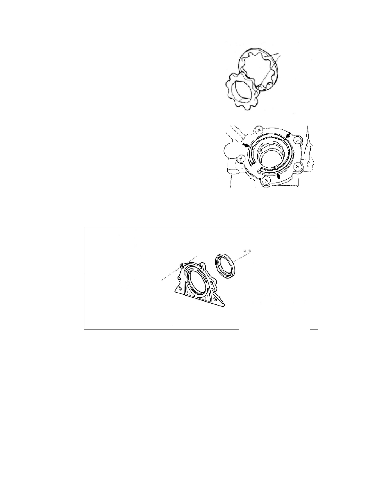
95
4.4.3. The marks of the exterior and
interior gears of the lubricating oil
pump should be on the visible side
when being assembled into the
pump body.
4.4.4. The new weather seal should be put
inside the oil pump cover groove.
5. Disintegrating and assembling of oil seal
5.1. Configuration diagram
Mark
※:Non-reusable part
Unit: N*m/kg*cm/Ft_Lb
Page 96
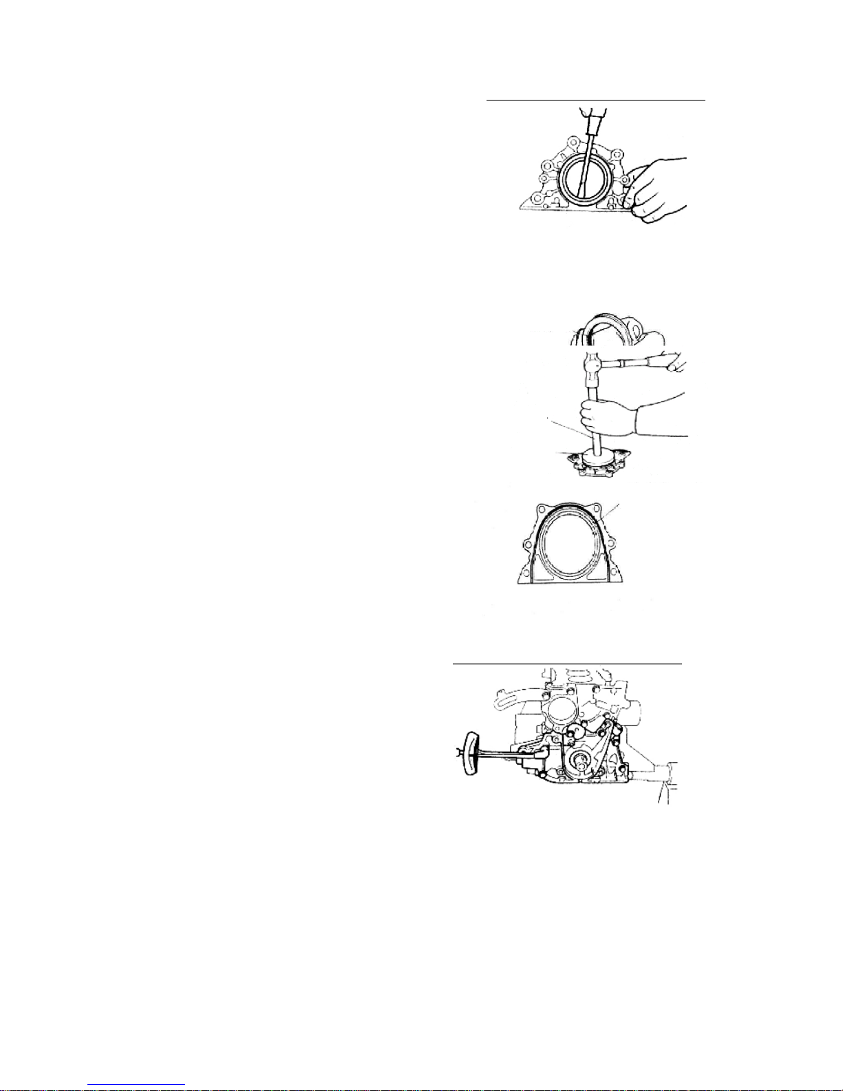
96
5.2. Disintegration
5.2.1. Use a flat screwdriver to remove the
rear oil seal.
Attention The oil seals are not reusable.
5.3. Checks
Check to see if the tears and wears of
the lip section of the oil seals are within
the normal conditions, and if there are
any damages in outer appearance.
5.4. Assembling
5.4.1. Smear lubricating oil on the new
oil seal lip section.
5.4.2. Install the oil seal shown as the
right figure.
6. Assembling
6.1. Assembling of the oil sealing
stands
Smear oil sealing silica on the oil
sealing stands shown as the right
figure.
[Grease] Letai 5699
Attention The liquid sealing silica is to
be smeared to the mating section of
the oil seal stands and cylinder body
surface, with a width of
3-4mm/0.118-0.157inch.
[Torque] 25±1.5N*m/18±1Ft_Lb
6.2. Assembling of new oil pump
washer, oil pump assembly
[Torque] 20±1.5N*m/14.5±1Ft_Lb
Oil sealing lip
SST
Seal line
Page 97
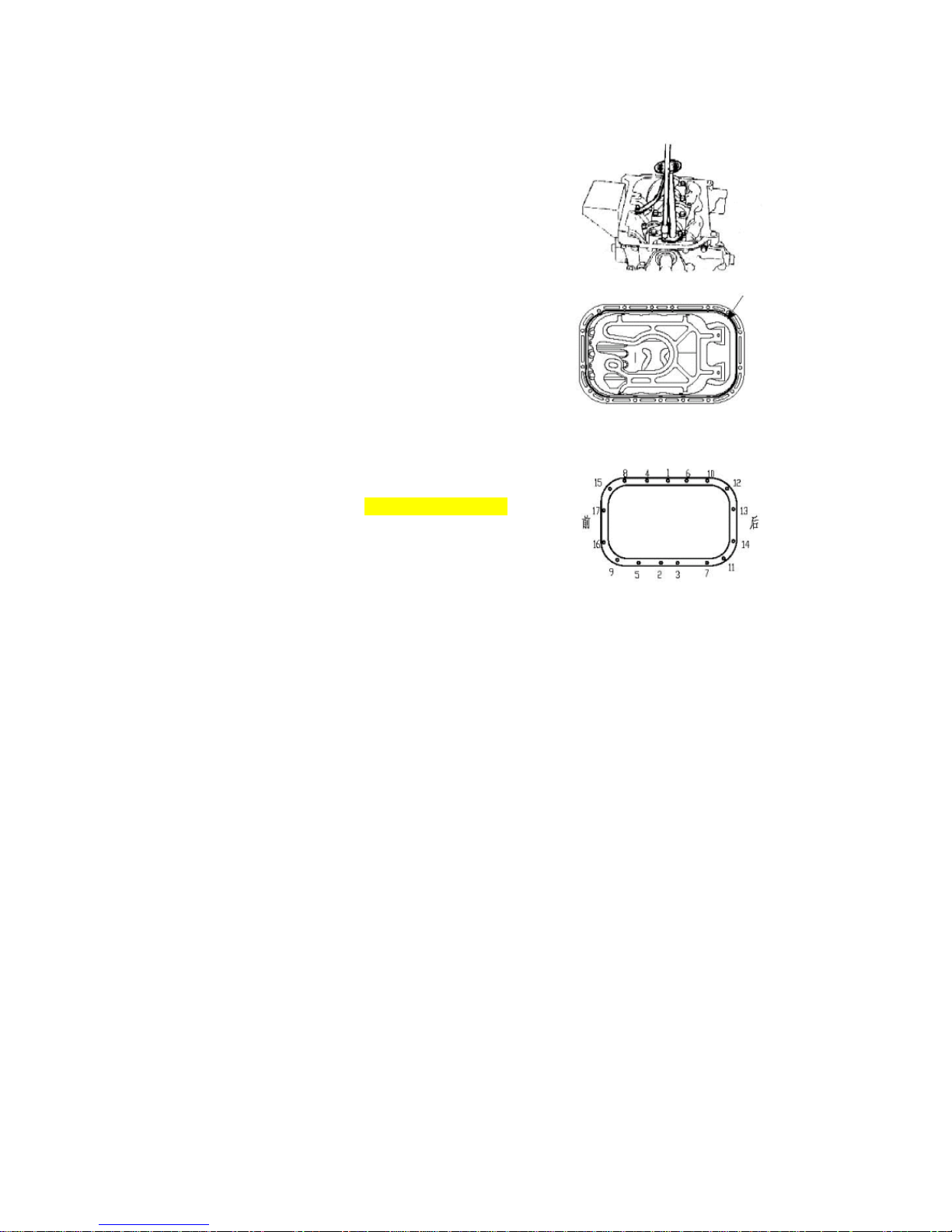
97
6.3. Installation of new lubricating oil collecting and
filtering device, oil pump collecting and filtering
device
[Torque] 6±1N*m/4.4±0.7Ft_Lb
6.4. Assembling of oil pan
6.4.1. Clear the mating surface with the cylinder body
6.4.2. Apply sealing silica before assembling
[Grease] Letai 5699
Attention
·The liquid cushion with silica line diameter of
Ф3-4mm/Ф0.1181-0.1574inch, without any broken section
·Make the assembly in 15 minutes after the
application of silica
6.4.3. Tighten in the sequence shown in the right
figure with the torque of 6±1N*m/4.4±0.7Ft_Lb from the center to
the two sides
Front
Rear
Page 98

98
Crankshaft connecting rod mechanism
1. Configuration diagram (Dismount and assemble the oil pump in the follow
sequence)
(1) Connecting rod cover(2) Connecting rod bearing bush(3) Piston and connecting rod
assembly(4) Main bearing cover(5) Crankshaft(6) Crankshaft bush(7) Thrust washer(8)
Cylinder block(9) No.1 compression ring(10) No.2 compression ring(11) Oil ring(12)
Piston(13) Connecting rod(14) Piston pin
※:Non-reusable part
Unit: N*m/kg*cm/Ft_Lb
Page 99

99
2. Disintegration of crankshaft connecting
rod mechanism
2.1. Check the connecting rod axial clearance
2.1.1. Use centimeter or feeler to measure axial
spacing
[Benchmark]:0.15-0.24mm/0.0059-0.0094inch
[Limit]:0.30mm/0.0118inch
2.2. Check the connecting rod bush vertical
clearance
2.2.1. Remove the bush cover
Attention: Parts and components of various
cylinders should be placed in good order.
2.2.2. Clean the bush and axle diameter
2.2.3. Place clearance gauge on the
connecting
bearing diameter.
Tighten bush cover according to regulated
torque
torque: 40±2N*m/28±1.5Ft_Lb
Attention Do not turn the crankshaft
2.2.4. Remove the bush cover, measure the
maximum width of the spacing ruler
[Benchmark]: 0.020-0.044
mm/0.0008-0.0017inch
[Limit]: 0.07 mm/0.0027inch
Page 100
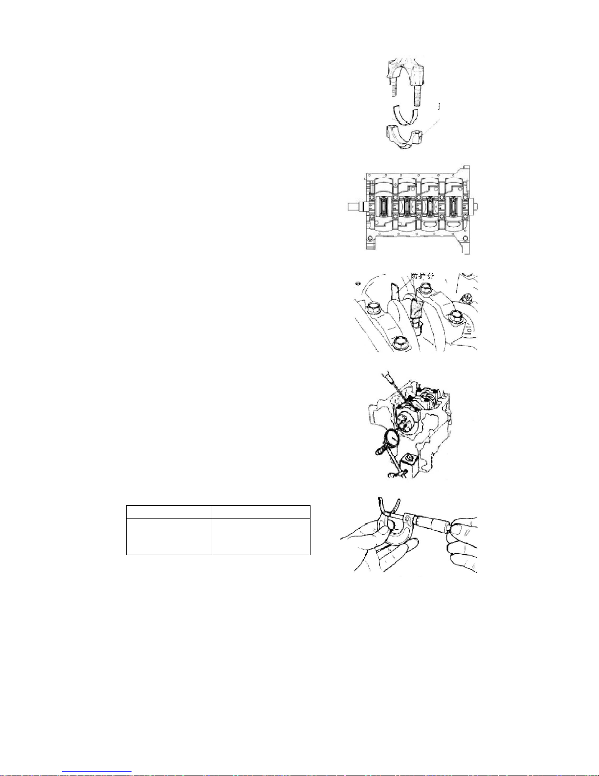
100
2.2.5. Replace the bush if width is beyond the
limit.
Attention:
·In replacing the bushes, you should use the
products
of same brand and from the same manufacturer,
which
can accord with the request of clearings.
2.2.6. Removal of connecting rod bearing cover
and
connecting rod bush
2.2.7. The threaded section of the connecting rod
bolt is
to be equipped with protective sleeve to prevent
from
scraping the cylinder hoe and crankshaft
connecting
rod axle diameter. Then knock the piston
connecting
rod out with the handle of a hammer.
Attention Put the parts and components of
various
cylinders in good order.
2.3. Use a caliper to measure the crankshaft
axial
clearance. If the axial clearance is above the
limits, it
is needed to replace the axial thrust washer or the
crankshaft.
[Benchmark]:0.089-0.211mm/0.0035-0.0083inch
[Limit]:0.30mm/0.0118inch
item
Benchmark value
Thickness of thrust
Face(mm/inch)
1.9
-0.03
-0.11
/0.0748
-0.0012
-0.0043
Connecting
rod bush
Connecting
rod cover
Lagging cover
 Loading...