

Page 1
VAX-1030 & VAX-1100
Multifunction meter for the measurement of direct current circuits
1. GENERAL INFORMATION
Dear customer,
thank you for choosing our product. In the following, we will show you how
to use your product.
Should you encounter any unexpected problems during use, please do not
hesitate to contact us.
The measuring instruments of the VAX series are multimeter which
transmit the measurement results to the display via a wireless 2.4 GHz
technology. A TFT-LCD shows the measured values clearly and enables a
comfortable operation.
The measuring instruments are safeguarded against overvoltage,
undervoltage and overcurrent. In operation with batteries, these devices
can detect automatically the direction of the current ow and displays the
battery capacity in real time.
Page 2

2. TECHNICAL SPECIFICATIONS
Model VAX-1030 VAX-1100
Measuring range voltage
Resolution voltage
Measuring range current
Resolution current
Relay
Measuring range
temperature
Charge indicator
Measuring range power
Resolution power
Measuring range
ampere hours
Resolution ampere hours
Measuring range
watt-hours
0 - 100 V
0,01 V
0,01 A
Internal
0 - 100 V
0,01 V
0 - 100 A0 - 30 A
0,1 A
External (optional)
-20 - 120 °C
0 - 100 %
0 - 200 kW
0,001 W
0 - 2000 AH
0,001 AH
0 - 4000 kWH
Resolution watt-hours
Measuring range time
Resolution time
Accuracy voltage
Accuracy current
Sampling rate
Range, wireless
Power consumption
measuring instrument
Power consumption
display
NCP
OCP
OVP
0,001 WH
0 - 99 days
1 seconds
± 2 % + 3 digits
± 5 % + 10 digits
5 Hz
Up to 10 m
ca. 0,4 W
0,5 W
0 - 300 A (setting of negative overcurrent protection)
0 - 300 A (setting of overcurrent protection)
0 - 100 V(setting of overvoltage)
LVP
delay of
protection settings
0 - 100 V(setting of undervoltage)
0 - 10 s
Page 3
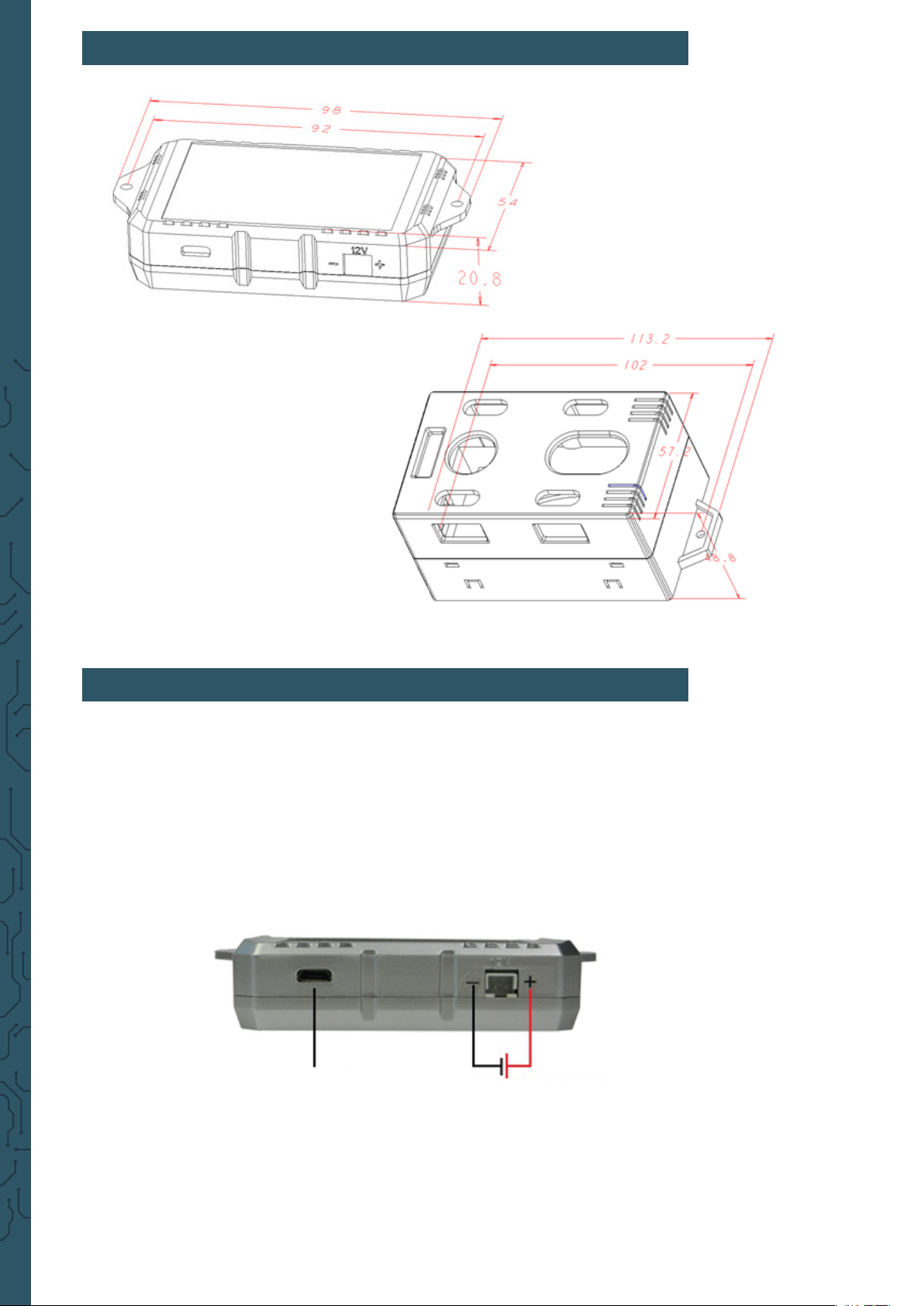
3. DIMENSIONS IN MM
4. DISPLAY
The measuring instrument can be connected with the display via a cable or
wireless.
If the connection is wireless, there are two opportunities to power the
display. You can use the mUSB port (5 V) or the JST port (8 - 16 V).
mUSB port JST port
Page 4

signal
power
charge status (for batteries)
key lock
relay
address
negative overcurrent protection
overcurrent protection
voltage
current
output
ampere hours
watt-hours
time
5. CONNECTION
VAX-1030
undervoltage protection
overvoltage protection
output (relay)
resetting
charge status
system settings
address settings
language setting
channel setting
power
source
load
battery
charger
If the instrument is integrated in the circuit like in the le illustration, it is
possible to measure DC current circuits and the discharge of batteries.
If the instrument is integrated in the circuit like in the right illustration, you
can measure the charging process of batteries.
Page 5

VAX-1100
For a measuring range from 10 to 100 V, the instrument must be connected
like that:
power
source
load
battery
charger
These illustrations display how the VAX1100 must be connected for a
measuring range from 10 to 100 V. Please note that the jumper must be
pinned on position 2W .
If the instrument is integrated in the circuit like in the le illustration, it is
possible to measure DC current circuits and the discharge of batteries.
If the instrument is integrated in the circuit like in the right illustration, you
can measure the charging process of batteries.
For a measuring range from 0 to 100 V, the instrument must be connected
like that:
power
source
load
battery
charger
These illustrations display how the VAX1100 must be connected for a measuring range from 0 to 100 V. Please note that the jumper must be pinned
on position 3W. Moreover, the measuring module must be supplied
with a 10 to 30 V DC voltage.
If the instrument is integrated in the circuit like in the le illustration, it is
possible to measure DC current circuits and the discharge of batteries.
If the instrument is integrated in the circuit like in the right illustration, you
can measure the charging process of batteries.
Page 6

Connection between a relay and the VAX1100
power
source
load
battery charger
You must note among the usage with a relay that the relay must be
designed for the expected voltage and current in that specic
construction.
6. OPERATION
There are displayed 3 possible symbols which are designed for the
verication of the connection. These symbols have this meaning:
Wireless connection is successfully established
Corded connection is successfully established
Connection failed or is not connected
Key Function
“OUT“
Hereby, you can switch the output. In order that it
works, the relay must be controlled.
Hereby, the protection against the negative current
“NCP“
can be activated. With “OK“ you can change the
value, if the value is “0“, the function is deactivated.
This function shis the relay to interrupt the circuit.
Hereby, the protection against overcurrent can be
“OCP“
activated. With “OK“ you can change the value, if the
value is “0“, the function is deactivated. This function
shis the relay to interrupt the circuit.
Page 7

“LVP“
“OVP“
Hereby, the undervoltage protection can be
activated. With “OK“ you can change the value, if the
value is “0“, the function is deactivated. This function
shis the relay to interrupt the circuit.
Hereby, the overvoltage protection can be activated.
With “OK“ you can change the value, if the value is
“0“, the function is deactivated. This function shis
the relay to interrupt the circuit.
“CLR“
“BAT“
“SET“
“ADR“
“LNG“ You can change here the language.
“FCH“
“BRI“ You can adjust here the brightness of the display.
This buttons deletes all saved values of Ah, Wh and
time. Additionally, the battery status is set on 100 %.
You can adjust here the values of the battery with this
button.
You can adjust here the fundamental setteings of the
device.
With “ADR“ the communication address can be
adjusted.
With “FCH“ the communication channel can be
adjusted.
Important: To go to the “LNG“ option, you must enter “ADR“ and hold down
the down arrow key for 3 seconds.
7. CONNECTING SEVERAL DEVICES TO ONE DISPLAY
To connect several devices to one display, you must rst assign dierent
addresses to the devices.
1. To do this, connect your display to your device using the USB cable.
2. Now open the menu by pressing the OK key.
3. Use the arrow keys to navigate to the ADR. menu item and press the OK key.
4. Now you can select the address with the arrow keys. By changing the
address you should now see the following symbol in the upper le corner of
the display:
5. To conrm the address, press and hold the OK button for about three
seconds.
6. If you now release the key, the display should change and the following
symbol appears:
In this way, you can assign dierent addresses to each device.
Page 8

In order to control the individual devices wirelessly, the address of your
display and that of the device you want to control must match.
1. To do this, connect the display to a voltage source.
2. Now open the menu by pressing the OK key.
3. Use the arrow keys to navigate to the ADR. menu item and press the OK key.
4. You can now select the address with the arrow keys.
5. To conrm the address, press the OK button.
If the wireless connection is successful, you should see the following symbol in
the upper le corner of your display:
8. DECLARATION OF CONFORMITY
Hereby, the Simac Electronics Handel GmbH declares that the radio
equipment type COM-VAX1030 and COM-VAX1100 are in compliance with
Directive 2014/53/EU. The full text of the EU declarations of conformity are
available at the following internet addresses:
www.simac-gmbh.de/CE/com-vax1030.pdf
www.simac-gmbh.de/CE/com-vax1100.pdf
Information on transmission power and frequency band of COM-VAX1030:
Frequency band: 2412-2472 MHz
Max. transmisson power: 11,67 dBm
Information on transmission power and frequency band of COM-VAX1100:
Frequency band: 2412-2472 MHz
Max. transmisson power: 11,67 dBm
9. SUPPORT
If any questions remain open or problems arise aer your purchase, we are
available by e-mail, telephone and with a ticket support system to answer
these.
E-Mail: service@joy-it.net
Ticket-System: http://support.joy-it.net
Telephone: +49 (0)2845 98469 – 66 (10 - 17 o‘clock)
For further information visit our website:
www.joy-it.net
Published: 01.10.2020
SIMAC Electronics GmbH
Pascalstr. 8 47506 Neukirchen-Vluyn
www.joy-it.net
 Loading...