

3
MotoDriver2
Ausgabe 19.05.2017 Copyright by Joy-IT 1

3
Index
1. Introducon
2. PIN Assignment
3. Connecng to an Arduino Uno
4. Usage
MotoDriver2
Ausgabe 19.05.2017 Copyright by Joy-IT 2

Dear customer,
thank you for purchasing our product. Please nd our instrucons below.
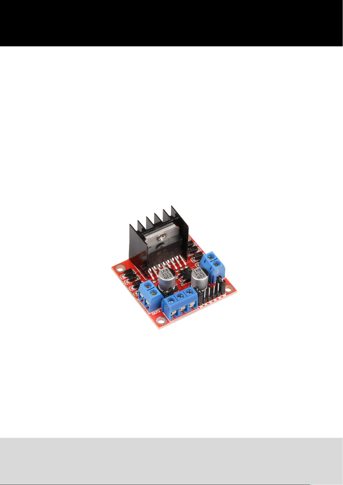
1. Introducon
The MotoDriver2 is an extension-board which allows you to cotnrol and use up to two direct-current
motors at once.
The motors can be controlled with a constant voltage from 5V to 35V.
Technical Specicaon
Model SBC-MotoDriver2
Driver L298N
Logical voltage 5V
Drive Voltage 5V— 35V
Drive Current 2A
Power Max. 25W
Dimensions (L x B x H) 43mm x 43mm x 27mm
Scope of delivery MotoDriver2
EAN 425023681513
Ausgabe 19.05.2017 Copyright by Joy-IT 3

2. PIN Assignment
Note: Remove the Jumper at posion 3 if your power supply is above 12V.
This acvates the power supply for the on-board 5V regulator.
The 5V output is perfect for supplying power to an Arduino.
This output is only acve, if the jumper on posion 3 is set.
PIN Belegung
1 DC Motor 1 / Stepper Motor +
2 DC Motor 1 / Stepper Motor GND
3 12V Jumper
4 Power Supply +
5 Power Supply GND
6 5V Output (if Jumper 3 is in place)
7 DC Motor 1 Jumper
8 Input 1
9 Input 2
10 Input 3
11 Input 4
12 DC Motor 2 Jumper
13 DC Motor 2 / Stepper Motor +
14 DC Motor 2 / Stepper Motor GND
Ausgabe 19.05.2017 Copyright by Joy-IT 4

3. Anschluss an einen Arduino Uno
MotoDriver 2 Arduino
Input 1 9
Input 2 8
Input 3 7
Input 4 6
The power supply for the MotoDriver2 (PIN 4) needs to between 5V and 35V, depending on your setup.
Ausgabe 19.05.2017 Copyright by Joy-IT 5

4. Verwendung
To use the motors with the module, connect the motors, the module and your Arduino as seen in the
image before.
Transfer the following code-example to your Arduino to test the funconality.testen.
//Motor 1
const int motorPin1 = 9;
const int motorPin2 = 8;
//Motor 2
const int motorPin3 = 7;
const int motorPin4 = 6;
int speed = 180;
void setup(){
//Set pins as outputs
pinMode(motorPin1, OUTPUT);
pinMode(motorPin2, OUTPUT);
pinMode(motorPin3, OUTPUT);
pinMode(motorPin4, OUTPUT);
//Motor Control A in both directions
analogWrite(motorPin1, speed);
delay(2000);
analogWrite(motorPin1, 0);
delay(200);
analogWrite(motorPin2, speed);
delay(2000);
analogWrite(motorPin2, 0);
//Motor Control B in both directions
analogWrite(motorPin3, speed);
delay(2000);
analogWrite(motorPin3, 0);
delay(200);
analogWrite(motorPin4, speed);
delay(2000);
analogWrite(motorPin4, 0);
}
void loop(){
}
Ausgabe 19.05.2017 Copyright by Joy-IT 6
 Loading...