

Page 1
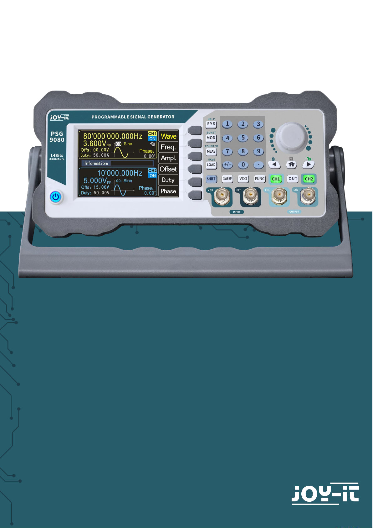
PSG 9080
Programmable signal generator
Page 2

1. TABLE OF CONTENTS
1. General information
2. Safety instructions
3. Overview front and rear side
4. Function keys
5. Screen overview
6. Basic first steps
7. Modulation mode
8. Measuring mode
9. Sweep mode
10. Voltage Control Mode (VCO)
11. Programming mode
12. System settings
13. Troubleshooting
14. Additional information
15. Support
1. GENERAL INFORMATION
Dear customer,
thank you very much for choosing our product.
In the following, we will introduce you to what to observe while starting up
and using this product.
Should you encounter any unexpected problems during use, please do not
hesitate to contact us.
The PSG9080 function/arbitrary waveform generator can output basic
waveforms (sine wave, square wave, triangle wave, pulse wave and custom
waveforms) from one of the channels individually or both channels simultaneously. At start-up, the two channels are configured to output a sine
waveform with a frequency of 10kHz and an amplitude of 5Vpp by default.
Users can configure the unit to output dierent basic waveforms.
The PSG9080 has these functions: Amplitude, frequency, phase modulation, amplitude shi keying, frequency shi keying, phase-shi keying, pulse
width modulation and burst function. It can measure the frequency, period
and length of input signals and count the periods. It also has a sampling
mode and a voltage control mode.
The button layout and 3.5" colour LCD are intuitive and easy to use. You
can save several settings in groups so you can load them quickly. The
menu can be set in German, English and French.
Page 3

2. SAFETY INSTRUCTIONS
Please observe the following safety instructions before operating the unit
in order to avoid damage to the unit and the connected devices, as well
as injuries!
The unit is operated with a dangerous voltage,
Never open the casing when it is connected to the power supply.
There is a risk of electric shock!
To avoid short-circuiting or electric shock, only use a suitable mains
cable.
Prevent electrostatic discharges.
Do not supply power to the unit if any connections, wires
or components are exposed.
Do not operate if there is suspected failure or damage to the unit.
Do not operate the unit without covers or with screens removed.
Overvoltages, e.g. from a lightning strike, can damage the unit and cause
electric shocks.
Never use the unit in humid, very dusty environments or near open fire or
chemicals.
Operate the unit only at an ambient temperature between 10 °C and
50°C.
Make sure that the unit is suiciently ventilated during operation to avoid
overheating. Do not block the ventilation slots or insert any objects.
Check the unit when unpacking it for the first time and before operating
it. If there is any damage to the unit, please contact your supplier or us
directly.
Page 4
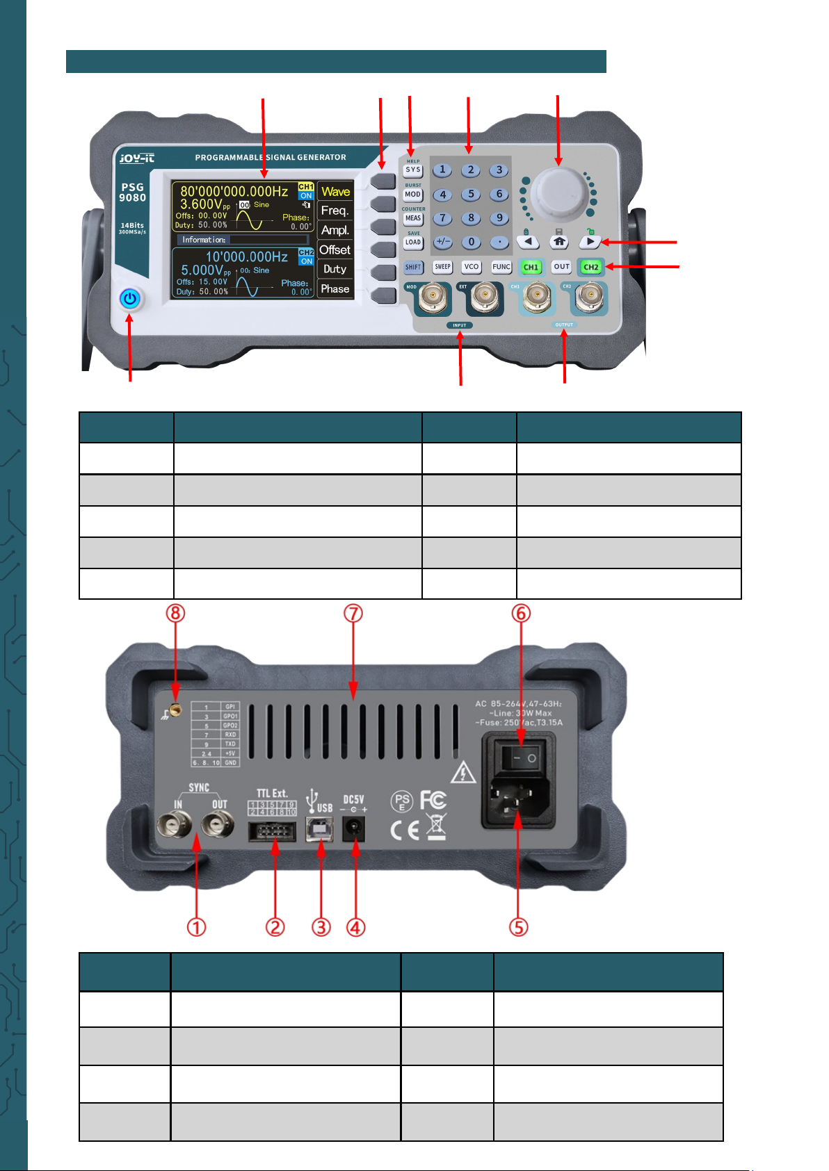
3. OVERVIEW FRONT AND REAR SIDE
Number Description Number Description
1 SYNC Connectors 5 AC Power connection
2
TTL-Connector (For use with
PC soware)
6 On-o switch
3
USB Interface (For use with PC
soware)
7 Ventilation holes
4 DC Power connection 8 Case earth connection
Number Description Number Description
1 On-o button 6 Rotary encoder + button
2 Signal inputs 7 Numeric keypad
3 Signal outputs 8 Function keys
4 Channel control buttons 9 Menu keys
5 Direction buttons, Home button 10 LC Display
①
②
⑦
⑧
③
④
⑤
⑥
⑨ ⑩
Page 5
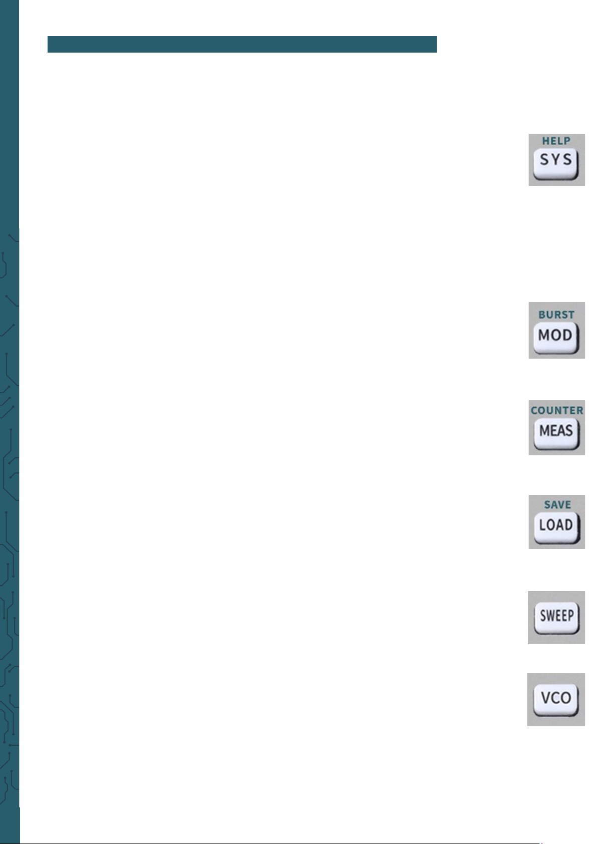
4. FUNCTION KEYS
The function keys (front side no. 8):
• SYS: The system settings key. It is used to quickly switch between the main menu
and the system settings.
- Press this button to open the settings menu and then press the menu button Page
to move to the next page. Press the menu buttons to select one of the setting
options such as Clear Memory, Sound, Brightness, Language, Built-in Wave
Number, Custom Wave Number, Waveform Loading Method, Synchronization,
Factory Default, System Colour and other items.
For more product information:
Press the SYS button to get the unit information including model and serial
number.
- Press SHIFT + SYS to quickly enter the system help function.
• MOD: The modulation key. It is used to quickly switch between the main menu and
the modulation menu.
- Press this key to open the modulation menu. Here, press the TYPE menu key to
switch between the functions amplitude modulation, frequency modulation, phase
modulation, ASK, FSK, PSK, PWM and burst.
- Press SHIFT + MOD to quickly call up the burst function.
• MEAS: The measuring mode button. It is used to quickly switch between the main
menu and the measurement mode menu.
- Press MEAS and the CNTR. and MEAS. Menu buttons in the measuring mode
menu to switch between the measuring and counting functions.
- Press SHIFT + MEAS to quickly switch to the count function.
• LOAD: The load button. It is used to call up the parameters of the memory loca-
tions.
-Use the numeric keypad to select the position to load, then press LOAD to quickly
load the parameters of the desired position.
- Press SHIFT + LOAD to quickly save the parameters.
• SWEEP: The sweep key. It is used to quickly switch between the main menu and the
sweep mode menu.
- Press SWEEP to enter the sweep menu and press FUNC to switch between frequency sweep, amplitude sweep and duty cycle sweep.
• VCO: The VCO key is used to switch between the main menu and the voltage control
menu.
- Press VCO to enter the voltage control menu and press the FUNC menu key to
switch between the frequency control, amplitude control and duty cycle control
functions.
Page 6

• FUNC: The function key. It is used to quickly switch between the main menu and
the programming mode.
- Press FUNC to enter programming mode. Press the MODE menu button to switch
between Normal Mode and Debug Mode.
• Button: The Home button.
- Press the -button to return to the standard screen.
- Press and hold to quickly save the data to the M00 position.
Page 7
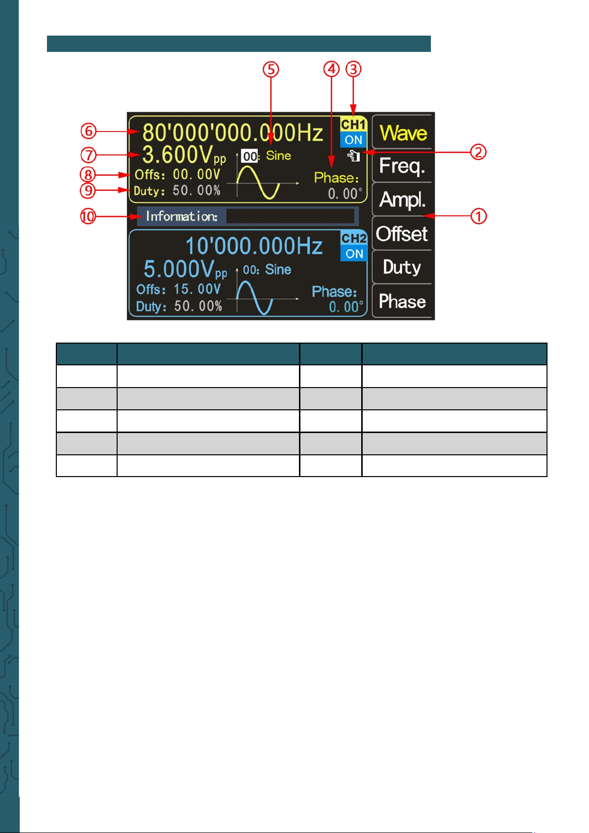
1.: The menu buttons display the operation menu of the currently selected function.
2.: The current finger cursor is on the CH1 interface, this means that the currently selected
channel is CH1 and the change of parameters is only valid for this channel.
By pressing the CH2 button, the finger cursor can be moved to the CH2 interface, now the
parameters for channel CH2 can be set
3.: The current channel status shows the on/o status of the current channels. ON indicates
that the channel output is on and OFF indicates that the channel output is o. With the
channel control keys CH1 and CH2, the respective channel can be switched on or o. Press
the channel control button OUT to switch the output status of CH1 and CH2 on or o simul-
taneously.
4.: Phase shows the phase-shi of the current waveform of channel 2, in relation to the wave
output at channel 1. No phase-shi can be set on channel 1. Aer pressing the corresponding menu key, you can use the direction keys to select the value and the rotary knob to
change the parameter.
You can also use the numeric keypad to set the phase-shi.
5.: The waveform display shows the currently set waveform of the channel.
By pressing the Wave menu button, you can change the waveform using the rotary knob or
the numeric keypad.
5. SCREEN OVERVIEW
Number Description Number Description
1 Menu buttons 6 Frequency
2 Finger cursor 7 Amplitude
3 Current channel status 8 Oset
4 Phase 9 Duty cycle
5 Waveform display 10 Information box
Page 8
6.: Press the Freq. menu key to select "Frequency", use the direction keys to select the value
you want to edit, then turn the knob to change the value. You can also change the value by en-
tering it using the numeric keypad and then pressing the corresponding menu button to select
the unit. Press the Freq. menu button twice and you can select the appropriate frequency unit
(MHz, kHz, Hz, mHz, μHz).
7.: This number indicates the voltage of the current channel. Press the Ampl. menu key to select " Amplitude", use the direction keys to select the value to edit and turn the knob to change
the value. You can also change the value by entering the value with the numeric keypad and
then pressing the corresponding menu button to select the unit. The unit is Vpp or mVpp.
8.: Os: indicates the set oset for the channel. By pressing the Oset menu button, you can
adjust the oset. Use the direction keys to select the value you want to edit, then turn the
knob to change the value. You can also change the value by entering it using the numeric
keypad and then pressing the corresponding menu key to select the unit. The oset is always
in volts.
9.: Duty: zeigt die Einschaltdauer der aktuellen Wellenform des Kanals an. Drücken Sie Duty,
um die Einschaltdauer hervorzuheben, wählen Sie mit den Richtungstasten den zu bearbeitenden Wert aus, und drehen Sie dann den Drehknopf, um den Wert zu ändern. Sie können
den Wert auch ändern, indem Sie ihn über die numerische Tastatur eingeben und dann die
entsprechende Menütaste zur Auswahl der Einheit drücken. Die Einschaltdauer wird in % angegeben.
10.: Information: shows the entered value and the position of the stored and loaded data.
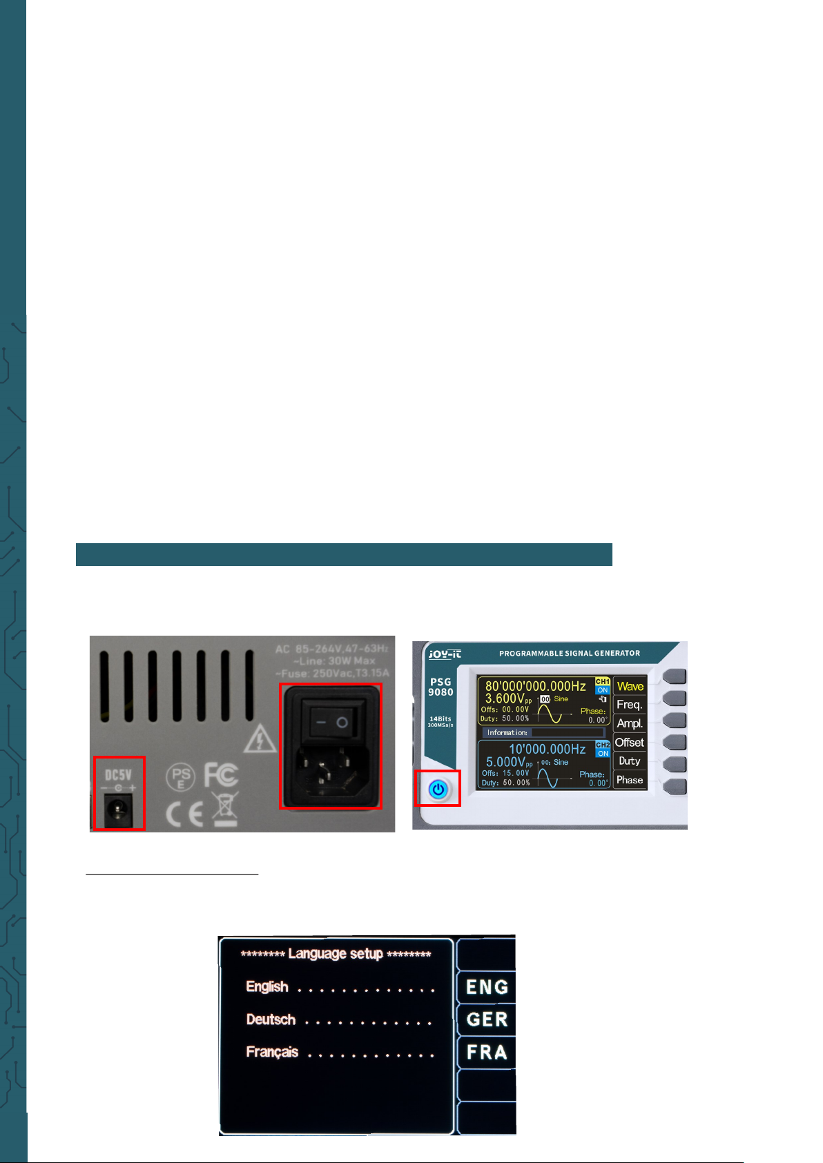
To start the unit, connect an 85 V - 264 V AC, or a 4.8 V - 5 V 3A DC power source to the back of
the unit and press the on/o switch.
Set the system language:
Aer the start screen is displayed, you can set the language. Press the corresponding menu
key to select the desired language. The next time you start, you will not have to set the language again.
6. BASIC FIRST STEPS
Page 9

To select the output channel:
Press the CH1 or CH2 channel control button to select the CH1 or CH2 channel. You can see
which channel is currently selected by the finger cursor.
Select the waveforms:
Press the Wave menu button. The menu button bar on the right side of the screen shows the
waveform. Press the desired menu key for the waveform or change the waveforms with the
rotary knob to output the desired waveform.
In addition, you can adjust the waveform with the numeric keypad.
Set the frequency:
Press the menu key Freq. to highlight "Frequency", now enter the value of the desired frequency using the numeric keypad and then select the desired unit using the menu keys. You
can also use the direction keys and the rotary knob to set the value of the parameter: Move the
cursor with the direction keys to select the digit to edit, then turn the knob to change the value
and set the frequency to the desired frequency; the frequency range is 0~80MHz.
Press the Freq. menu button again to select the frequency unit: MHz, KHz, Hz, mHz, μHz.
Page 10

Set the amplitude:
Press the Ampl. menu button to highlight "Amplitude" and use the numeric keypad or
turn the knob to set the desired amplitude value.
The amplitude range is limited by the frequency setting. The higher the frequency, the
smaller the output amplitude range.
Adjusting the oset:
Press the Oset menu button to highlight "Oset" and use the direction buttons and
rotary knob or numeric keypad to adjust the parameters and set the oset to the desired value.
The amplitude range is aected by the oset setting, the larger the oset, the smaller
the amplitude range. When the DC level is selected for the waveform, the oset is the
voltage value of the DC level (the amplitude value cannot be 0).
Setting the duty cycle:
The duty cycle cannot be set on every waveform, so sometimes the duty cycle is disabled on the screen.
Press the Duty menu button to highlight "Duty Cycle" and use the direction buttons
and rotary knob or numeric keypad to set the parameters. The default duty cycle is
50%. The waveform is switched to pulse wave and the duty cycle is continuously adjustable between 0.01-99.99%.
Adjust the phase:
Press CH2 to select CH2. At this time, the finger cursor to the right of the CH2 interface
on the screen is on.
On the CH2 interface, press the Phase menu button to highlight Phase and use the arrow keys and knob or numeric keypad to set the parameters. The phase dierence is
0.00° by default. Before setting the phase dierence, you should activate the frequency synchronization in the system settings.
Observe the output waveforms:
Use the BNC test lead to connect CH1 and CH2 of the PSG9080 to an oscilloscope. Observe the waveforms on the oscilloscope. It is recommended to use our standard BNC
test lead with a connector to test the square wave so that overshoots are low and
waveforms are stable.
Load and save the parameters:
Press and hold the Home button to quickly store the parameters in the M00 position,
or you can enter the stored position using the numeric buttons and then press the
SHIFT + LOAD buttons to store a total of 100 memory positions 00-99.
Enter the desired position using the numeric keys and then press the LOAD key to load
the parameters of the memory position.
Frequency < 1 MHz
≥ 1 MHz
< 11 MHz
≥ 11 MHz
< 30 MHz
≥ 30 MHz
< 61 MHz
≥ 61 MHz
≤ 80 MHz
Amplitude
range
2 mVpp
~
25 Vpp
2 mVpp
~
20 Vpp
2 mVpp
~
10 Vpp
2 mVpp
~
5 Vpp
2 mVpp
~
3,6 Vpp
Page 11

7. MODULATIONSMODUS
The PSG9080 can output modulated waveforms in single or dual channels. Modulation is the
process of processing the information from the signal source and adding it to the carrier to
make it suitable for channel transmission. It is the technology that changes the carrier with
the signal. The carrier wave can be a sine wave, square wave, pulse wave, arbitrary wave
(except DC signal wave). The modulated wave can be from an internal modulation source or
an external modulation source. Modulation types supported by PSG9080 include AM, FM, PM,
ASK, PSK, FSK, pulse and burst.
Select the modulation mode:
Press MOD and then → Type now you can select the desired modulation mode with the menu
buttons or the rotary knob.
Select carrier waveforms:
Press Sharp and use the rotary knob to select the desired carrier waveform. The dierent settings of several parameters of the carrier waveforms (such as frequency, amplitude, oset,
etc.) aect the output of the modulated waveform. For dierent carrier waveforms, the adjustable range of each carrier parameter is also dierent (in relation to the model of instrument you are using and the selected carrier waveform, see "Specifications" for details).
For the setting method of the carrier parameters, please refer to the corresponding introduction in the section "Basic Output Waveform".
Selecting the source:
The PSG9080 can accept modulation waveforms from internal or external modulation
sources.
Press Source to select "Internal" or "External" modulation source.
Internal source:
Aer selecting the internal modulation source, press the Sharp menu button to select sine
wave, square wave, triangle wave, ascending exponential, descending exponential or any
wave as the modulation source. The default is sine wave.
External source:
When the external modulation source is selected, the signal generator accepts the external
modulation signal input via the MOD connector on the front panel.
The frequency range of the external signal is 0~20kHz, and the amplitude range is -5V~+5V.
Setting the carrier frequency:
Aer using the modulation source "Internal", press the menu key Carr.F to set the carrier fre-
quency. Use the numeric keyboard or the direction keys and the rotary knob to enter the desired frequency value.
The frequency range is 0.001 Hz to 1 MHz and the default is 500 Hz.
Setting the modulation wave frequency:
Aer using the "internal" modulation source, press the menu key Mod.F to set the frequency
of the modulated wave. Use the numeric keyboard or the direction keys and the rotary knob
to enter the desired frequency value.
The modulation frequency range is from 0.001 Hz to 1 MHz and the default is 500 Hz.
Page 12

AM
Amplitude modulation is a modulation method in which the amplitude of the carrier wave
changes according to the desired transmission signal, but the frequency remains unchanged.
Setting the modulation depth:
The modulation depth indicates the degree of amplitude change, expressed as a percentage.
The range of the amplitude modulation depth can be set from 0% to 200%. Press the menu
button Depth to set the amplitude modulation degree.
FM
Frequency modulation is a modulation method that changes the carrier frequency according
to the modulation signal. The magnitude of the frequency change of the modulated wave is
determined by the magnitude of the modulation signal, and the period of the change is determined by the frequency of the modulation signal.
Set the frequency deviation:
Frequency deviation refers to the deviation of the frequency of the modulation waveform relative to the carrier frequency. Press the menu key FM.Dev to set the FM frequency deviation.
PM
Phase modulation is a modulation method in which the deviation of the carrier phase from its
reference phase changes proportionally to the instantaneous value of the modulation signal.
Adjust the phase deviation of the modulation wave:
Phase deviation refers to the change in phase of the modulated waveform relative to the carrier phase. Press the menu key PM.Dev to adjust the phase deviation of the phase modulation.
Use the numeric keyboard or the direction keys and the rotary knob to enter the desired deviation value.
The adjustment range of the phase deviation is 0°to 359.9°, and the default value is 180°.
ASK
The modulation method that uses the digital baseband signal to control the amplitude variation of the carrier wave is called Amplitude Shi Keying (ASK), also known as digital amplitude modulation.
Setting the polarity:
Press the Polar menu button to select the amplitude of the modulated wave controlled by
"positive polarity" or "negative polarity".
Setting the ASK amplitude:
Press the Ampl. menu button to set the ASK amplitude.
Use the numeric keyboard or the direction keys and the rotary knob to enter the desired
amplitude value.
The ASK amplitude range is 0%-200%, the default is 80%.
FSK
The modulation method used to control the change in carrier frequency is called frequency
shi keying (FSK).
Set the polarity:
Press the Polar menu button to select the amplitude of the modulated wave controlled by
"Positive Polarity" or "Negative Polarity".
Set the hop frequency:
Press the menu button Hop.F to set the hop frequency.
Use the numeric keyboard or the direction keys and the rotary knob to enter the desired frequency value.
Page 13

PSK
Phase-shi keying (PSK): With phase-shi keying, the phase of the output signal is shied by
the set phase, depending on the logic level of the source signal.
Setting the polarity:
Press the Polar menu key to select the amplitude of the modulated wave controlled by
"positive polarity" or "negative polarity".
If the polarity is set to "positive polarity", a high level at the source signal shis the output signal by the set phase. If the polarity is "negative", the phase of the output signal is shied at a
low level.
Setting the phase:
Press the Phase menu button to set the PSK phase.
Use the numeric keyboard or direction keys and the rotary knob to enter the desired frequency value.
The PSK phase range is 0° to 359.9°.
PWM
Digital adjustment of the pulse width and pulse period time of the pulse wave can be achieved, which is more accurate than setting the duty cycle. The pulse modulated waveform can
only be a square wave. This method varies the ratio of the on-time to the specified period duration.
Set the wave inversion:
When you press the W.Inv menu button, you can select Normal and Inv. to control the output.
Set the pulse width:
Press the menu key Width to set the pulse width.
Use the numeric keypad or the direction keys and the rotary knob to enter the desired value
(the unit can be us, ms, s).
The pulse width range is 0.001us to 4s, and the default is 0.100us.
Set the pulse period:
Press the Period menu button to set the pulse duration.
Use the numeric keypad or the direction keys and the rotary knob to enter the desired frequency value.
The period length range is from 0.001us to 40s, and the default is 10.00us.
Burst-Function
With the burst function, individual signal pulses can be sent.
The signal generator can be set to output 1-10000000 burst signals. Trigger modes include an
internal trigger, external trigger (rising edge) and manual trigger. When using it, note that the
period of the burst signal should be smaller than the period of the trigger signal.
Setting the Idle mode:
Press the menu key Idle You can select zero, positive maximum and negative maximum of the
control output.
Set trigger source:
Press the T.Src menu button to select the trigger mode.
Menu key Button: Single output can be achieved by pressing the menu button Trig.
Menu key Int.: Internal trigger: The signal can be output via the CH2 channel of the signal generator.
Menu key Ext.AC: External AC signal trigger.
Menu key Ext. DC: External DC signal trigger.
Page 14

Set the number of pulses:
Press the Num. menu button to set the number of pulses.
Use the numeric keyboard or the direction keys and the rotary knob to enter the desired number of pulses. The number of pulses ranges from 1 to 100000000, the default is 1.
8. MEASURING MODE
Press MEAS to enter the measuring mode menu and press the CNTR. or MEAS. menu button
to switch between the counting and measuring functions.
Press SHIFT + MEAS to go directly to the counting function.
Measuring function
The measurement function can measure the frequency, period, positive pulse width, negative pulse width and duty cycle of the input signal. The measuring frequency range is 1Hz100MHz, the amplitude range of the measuring signal is 2Vpp-20Vpp. Measurements are taken via the EXT input.
Setting the coupling:
Press ▲ ▼ to set the cursor to coupling. Use the rotary knob to switch the coupling between
AC and DC.
Setting the gate time:
Press ▲ ▼ to move the cursor to the gate time position.
Use the numeric keyboard or the direction keys and the rotary knob to enter the desired gate
time.
The gate time range is from 0.001 s to 10 s and the default is 1 s.
Set the measurement mode:
Press ▲ ▼ to move the cursor to the measurement mode and use the rotary knob to switch
the measurement mode (low frequency <2kHz or high frequency >2kHz).
Measurement parameters: Frequency, period, positive pulse width, negative pulse width,
duty cycle.
Page 15

Counting function
The counting function calculates the number of input signal periods in real-time.
Set the coupling:
Press ▲ ▼ to set the cursor to coupling. Use the rotary knob to switch the coupling between
AC and DC.
Aer setting the coupling, you can press the ON button to start the counting function. Press
the OFF button to stop, the RST menu button to restore the default settings and the Save
menu button to save the parameters.
With the sweep function, a start and end value can be set, the set range is swept through in
the set time. This can be used for frequency, amplitude and duty cycle.
Press the SWEEP key to enter the sweep menu. Press the FUNC menu key to select the func-
tions frequency sweep, amplitude sweep and duty cycle sweep.
Press the SAVE key to quickly save the parameters in the M00 position. The menu for the fre-
quency sweep is shown in the illustration.
Sweep time:
Press ▲ ▼ to position the cursor on the sweep time and use the numeric keyboard or direc-
tion keys and knob to enter the desired sweep time. The range of sweep time is from 0.01 s to
640 s.
Sweep direction:
Press ▲ ▼ to position the cursor on the sweep direction, with three directions to choose
from: Rising, Falling and Rising & Falling.
Sweep mode:
Press ▲ ▼ to set the cursor to sweep mode, here you can choose between linear and loga-
rithmic mode.
Sweep Channel
Change the channel by pressing the CH1 or CH2 menu button.
9. SWEEP-MODE
Page 16

Sweep Frequency
Press the FUNC menu button to select the Sweep Frequency function. (S.Freq)
Start frequency and end frequency:
The start frequency and the end frequency are the upper and lower frequency limits of the fre-
quency sweep. You can set both with the direction keys and the rotary knob, or the numeric
keypad.
Turn on frequency sweep:
Press the ON button to start the frequency sweep. The frequency change can be observed on
the display.
Sweep Amplitude
Press the FUNC menu button to select the Sweep Amplitude function. (S.Ampl)
Start amplitude and end amplitude:
The start amplitude and the end amplitude are the upper and lower amplitude limits of the
amplitude run. You can set both with the direction keys and the rotary knob, or the numeric
keypad.
Turn on sweep amplitude:
Press the ON key to start the amplitude run-through. The amplitude change can be observed
on the display.
Sweep Duty Cycle
Press the FUNC menu button to select the sweep duty cycle function. (S.Duty)
Start duty cycle and end duty cycle:
The start duty cycle and end duty cycle are the upper and lower limits of the duty cycle's duty
cycle. You can set both with the direction keys and the rotary knob, or the numeric keypad.
Turn on the Sweep duty cycle:
Press the ON key to start the duty cycle. The duty cycle change can be observed on the dis-
play.
Page 17

VCO stands for voltage-controlled oscillator. A voltage-controlled oscillator is an electrical
oscillator whose frequency can be changed by the magnitude of an applied voltage. Press
VCO and the FUNC menu key to select the frequency control, amplitude control and duty cyc-
le control functions.
Press the SAVE menu key to quickly store the parameters in the M00 position.
VCO channel:
Press the CH1/ CH2 menu buttons or the rotary knob to switch between channels.
VCO mode:
Press ▲ ▼ to move the cursor to VCO mode. You can choose between linear and logarithmic
modes.
VCO Frequency
Press the FUNC menu button to select the frequency control. (V.Freq)
Start frequency and end frequency:
The start frequency and the end frequency are the upper and lower frequency limits of the
frequency sweep. You can set both with the direction keys and the rotary knob, or the numeric keypad.
Minimum voltage calibration and maximum voltage calibration:
The maximum and minimum values of the external input signal voltage can be calibrated. You
can set both with the numeric keypad.
Turn on VCO frequency:
Press the ON button to activate the function. The frequency change can be observed on the
display.
VCO Amplitude
Press the FUNC menu button in the voltage control menu to select amplitude control.
(V.Ampl)
Start amplitude and end amplitude:
The start amplitude and the end amplitude are the upper and lower amplitude limits of the
amplitude run. You can set both with the direction keys and the rotary knob, or the numeric
keypad.
Minimum voltage calibration and maximum voltage calibration:
The maximum and minimum values of the external input signal voltage can be calibrated. You
can set both with the numeric keypad.
10. VOLTAGE CONTROL MENU (VCO)
Page 18

11. PROGRAMMING MODE
Turn on VCO amplitude:
Press the ON button to activate the function. The amplitude change can be observed on the dis-
play.
VCO Duty Cycle
Press the FUNC button in the voltage control menu to select the duty cycle control (V.Duty).
Start duty cycle and end duty cycle:
The start duty cycle and end duty cycle are the upper and lower limits of the duty cycle's duty
cycle. You can set both with the direction keys and the rotary knob, or the numeric keypad.
Minimum voltage calibration and maximum voltage calibration:
The maximum and minimum values of the external input signal voltage can be calibrated. You
can set both with the numeric keypad.
Turn on VCO Duty:
Press the ON button to activate the function. The duty cycle change can be observed on the dis-
play.
Programming mode allows a sequence of dierent signals to be output automatically. Press
FUNC to enter the programming mode menu and the MODE menu key to switch between normal mode and debug mode.
In programming mode, press the SAVE key to save the data immediately.
Normal mode and debug mode
Press the MODE menu button to switch between normal mode and debug mode.
Under P00, debug mode is marked with * and normal mode with ●
In debug mode, the display continues to show the programming mode when the signals are
output, so that it can be recognized when the next signal is output and which one it is.
In normal mode, the display shows the home screen when the signals are output.
P00
P00 represents the memory position in programming mode. There are the group positions
P00-P19.
No.
The number 00 indicates an instruction, there are a total of 00-99 sets of instructions.
Load
M00 indicates the location where the parameter is stored.
Time
Time 00S indicates the current runtime of the instruction.
Time: 00:00:00:00/00:00:00 indicates the current run time/total run time.
Page 19

Press the SYS menu button to enter the system settings and press ▲ ▼ to select items such
as Clear Memory, Sound, Brightness, Language, Built-in Wave Count, arb Wave Count, Waveform Load, Methods, System Information, etc.
Clear Memory:
To erase the parameters stored in the current position, the rotary knob for setting is turned to
the specified position for erasing. The keypad can also be used to select the memory position.
Sound setting:
You can switch the sound on and o using the menu keys ON and OFF or the rotary knob.
Brightness setting:
You can quickly adjust the brightness using the numeric keys and the rotary knob.
Setting the language:
The German, English and French languages can be selected via the rotary knob or the menu
keys.
Build-in Waveforms:
The number of built-in waves of the instrument can be set using the numeric keys and the
knob. The setting range is from 00 to 21.
Arbitrary Waveforms:
The number of arbitrary waves of the instrument can be set using the number keys and the
knob. The setting range is from 01 to 99.
Waveform loading methods:
You can select the waveform loading methods Auto and Fast.
If you have selected Fast, the waveform is loaded with 2048 sample points.
If you have selected Auto, the waveform is loaded with up to 8192 sample points. We recommend setting the loading method to Auto.
Information about the system:
Press the About button to display the product model, hardware version, soware version,
FPGA version, oicial website and oicial QR code of this instrument.
12. SYSTEM SETTINGS
GoTo
The value in the GoTo field indicates the number of the instruction to jump to. If the value in
the GoTO field is 05, it is transferred to instruction no. 05 aer the current instruction is com-
pleted to start the run.
Loop
The value in the field indicates how oen the instruction is repeated; if the cycle is set to 05,
this means that the instruction is carried out 5 times.
Page 20

Change page:
Press the PgDn menu button to access the second page of the system settings.
Waveform synchronization:
The waveform synchronization can be switched on and o via the menu keys ON and OFF, or
the rotary knob. During synchronization, the parameters of the CH2 channel change with the
parameters of the CH1 channel.
Frequency synchronization:
Frequency synchronization can be switched on and o via the menu keys ON and OFF, or the
rotary knob.
Amplitude synchronization:
Amplitude synchronization can be switched on and o via the menu keys ON and OFF, or the
rotary knob.
Duty cycle synchronization:
The duty cycle synchronization can be switched on and o via the menu keys ON and OFF, or
the rotary knob.
External synchronization:
The external synchronization can be switched on and o via the menu keys ON and OFF, or the
rotary knob.
Frequency fine-tuning:
You can adjust the frequency to synchronise the waveform, the setting range is 0-99.
Recover to default settings:
The factory settings can be restored by pressing RUN.
System colour:
There are four system colours. You can select the desired system colour using the numeric
keys and the rotary knob and press the Save menu key to save the system colour.
Automatic Power-on:
You can switch the automatic Power-on on and o using the menu keys ON and OFF, or the
rotary knob. Aer turning on the automatic power-on function, the unit output is turned on by
default at start-up.
CH1/CH2 Amplitude fine-tuning:
If the output amplitude of the CH1/CH2 channel waveform diers slightly from the measured
amplitude, you can change the CH1/CH2 amplitude fine-tuning value and perform calibration
to obtain accurate amplitudes. The default value for the CH1/CH2 amplitude fine-tuning is 50.
Page 21

This chapter lists the common PSG9080 errors and their solutions. If you encounter these
problems, please solve them by following the appropriate steps. If the problem persists, please contact us.
The screen is still dark (no display) aer pressing the power button:
Check whether the power supply is connected correctly.
Check whether the power button is really pressed.
Restart the instrument aer completing the above checks.
The screen is too dark to see the content on the screen clearly:
Check if the brightness and contrast settings are too low.
Press the SYS key to enter the system settings menu, then press the ▲ ▼ key to move the cur-
sor to the brightness position and adjust the brightness of the screen to a suitable value using
the corresponding rotary knob.
The settings are correct but no waveform is generated:
Check if the BNC cable is firmly connected to the corresponding channel output connector
(CH1 or CH2).
Check if the BNC cable has internal damage.
Check if the BNC cable is firmly connected to the tester.
Check whether the signal output of CH1 or CH2 is switched on. If not, press the corresponding
button to turn on the signal output.
Aer completing the above checks, press the power button and restart the unit.
If it still does not work properly, please contact us.
13. TROUBLESHOOTING
Page 22

Veröentlicht: 26.02.2021
www.joy-it.net
SIMAC Electronics GmbH
Pascalstr. 8, 47506 Neukirchen-Vluyn
14. ADDITIONAL INFORMATION
Our information and take-back obligations according to
the Electrical and Electronic Equipment Act
(ElektroG)
Symbol on electrical and electronic equipment:
This crossed-out dustbin means that electrical and electronic appliances
do not belong in the household waste. You must return the old appliances
to a collection point.
Before handing over waste batteries and accumulators that are not enclosed by waste equipment must be separated from it.
Return options:
As an end user, you can return your old device (which essentially fulfils
the same function as the new device purchased from us) free of charge for
disposal when you purchase a new device.
Small appliances with no external dimensions greater than 25 cm can be
disposed of in normal household quantities independently of the purchase of a new appliance.
Possibility of return at our company location during opening hours:
SIMAC Electronics GmbH, Pascalstr. 8, D-47506 Neukirchen-Vluyn, Germany
Possibility of return in your area:
We will send you a parcel stamp with which you can return the device to
us free of charge. Please contact us by email at Service@joy-it.net or by
telephone.
Information on packaging:
If you do not have suitable packaging material or do not wish to use your
own, please contact us and we will send you suitable packaging.
15. SUPPORT
If there are still any issues pending or problems arising aer your purchase, we will support you by e-mail, telephone and with our ticket support
system.
Email: service@joy-it.net
Ticket system: http://support.joy-it.net
Telephone: +49 (0)2845 98469-66 (10-17 o‘clock)
For further information please visit our website:
www.joy-it.net
 Loading...