

Page 1
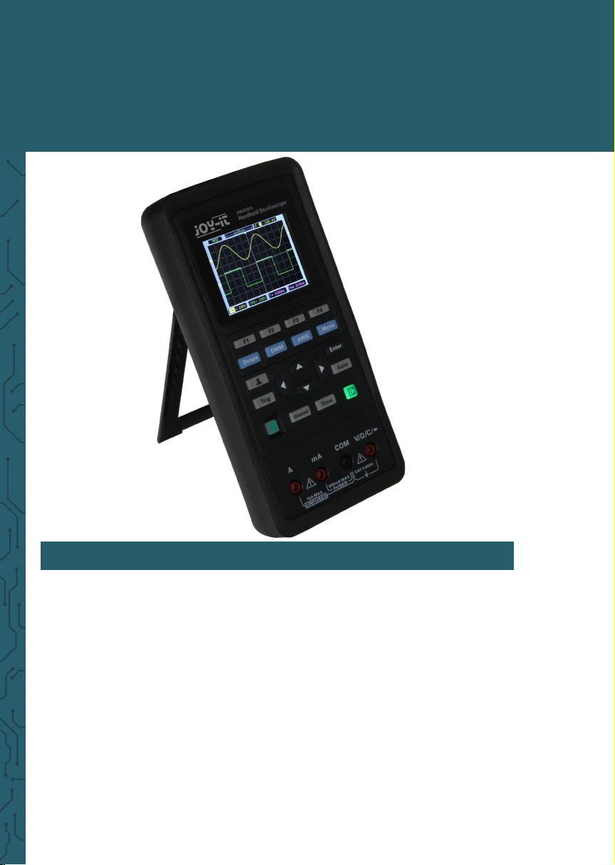
JT-DMSO2D72
Portable 3-in-one oscilloscope, signal generator and multimeter
1. GENERAL INFORMATION
Dear customer,
Thank you for choosing our product. Please read the following im-
portant information before putting the device into operation.
This oscilloscope is compact, portable and flexible. It has a TFT-LCD
color display with a resolution of 320 x 240 pixels and adjustable
backlight brightness.
The maximum real time sampling rate can be up to 250 MSa/s. USB
memory devices are also supported, the user can upgrade the firmware via USB, the edge trigger function is automatically detected and
it has a user-defined fast oset calibration with A/D converter that
can sample each channel simultaneously.
3
Page 2
2. SAFETY INSTRUCTIONS
Safety Terms and Symbols:
following terms may appear on product:
Danger It represents that harms may be caused to you at once if you per-
form the operation.
Warning It represents that latent harms may be caused to you if you per-
form the operation.
Notice It represents that damage may possibly caused to the product or
other properties if you perform the operation.
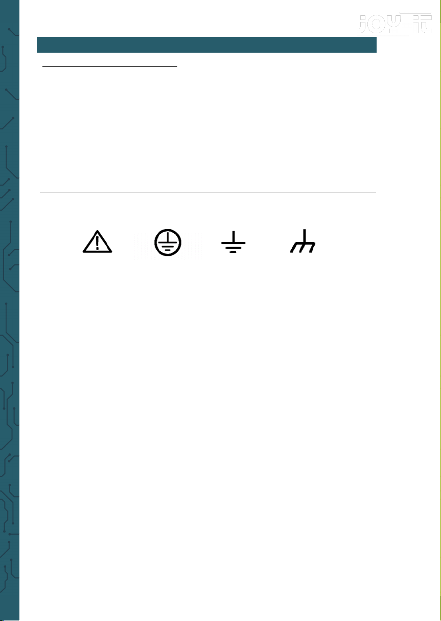
Symbols on the product: following symbols may appear on product:
General Safety Summary
Read the following safety precautions to avoid injury and prevent damage
to this product or any products connected to it. To evade potential hazards, use this product only as specified.
Only qualified personnel should perform maintenance.
Use suitable power cord. Use only the power cord specified for this prod-
uct and certified for the country of use.
Connect and disconnect properly. Connect a probe with the oscilloscope
before it is connected to measured circuits; disconnect the probe from the
oscilloscope aer it is disconnected from measured circuits.
Ground the product. This product is grounded through the grounding
conductor of the power cord. To avoid electric shock, the grounding con-
ductor must be connected to earth ground. Before making connections to
the input or output terminals of the product, ensure that the product is
properly grounded.
Notice
Please read
the manual
Protective
ground
terminal
Measuring
ground
terminal
Chassis
ground
terminal
Page 3

Connect the probe the right way. The probe ground lead is at ground po-
tential. Do not connect the ground lead to an elevated voltage.
Check all terminal ratings. To avoid fire or shock hazard, check all ratings
and markings on the product. Refer to the product manual for detailed information about ratings before making connections to the product.
Do not operate without covers. Do not operate this product with covers or
panels removed.
Avoid exposed circuitry. Do not touch exposed connections and compo-
nents when power is present.
Do not operate with suspected failures. If you suspect there is damage to
this product, have it inspected by qualified service personnel.
Assure good ventilation.
Do not operate in wet/damp environments.
Do not operate in an explosive atmosphere.
Keep product surfaces clean and dry.
3. TECHNICAL SPECIFICATIONS
Channels 2
Bandwidth 70 MHz
Sampling Rate 250 MSa/s Single channel
125 MSa/s Dual channel
Oscillospe Specifications: -Horizontal
Rising time ≤ 5 ns
Waveform Interpolation (sin x)/x
Record length 6000 samples Single channel
3000 samples Dual channel
SEC/DIV Range of 1, 2, 5 Sequence 5 ns/div - 500s/div
Oscilloscope Specifications: -Vertical
A/D converter 8-bit resolution
VOLTS/DIV range 10mV/div –10V/div at BNC input
Measurement Range ± 5 div
Rising time at BNC input, typical ≤ 5 ns
Page 4

Selectable analog bandwidth limit,
typical
Typical 20 MHz (reduced to 6 MHz when
using a 1x probe)
Low frequency response (-3db) ≤ 10 Hz
DC gain accuracy 10V/div - 10mV/div ±3% for normal or
Trigger
Type Edge
Mode Auto, Normal, Single
Level ± 4 divisions from centre of screen
Trigger level accuracy 0,2 div*volts/div within 4 div.
Slope Rising, falling, rising & falling
Source CH1, CH2
Input
Coupling DC, AC or GND
Input impedance (DC coupled)
25pF ±3pF, 1MΩ ±2%
Probe attenuation 1X, 10X
Supported probe attenuation factors 1X, 10X, 100X, 1000X
Input protection voltage 150 V
RMS
Measurement
Values between cursors Voltage Dierence: △V
Time Dierence: △T
Automatic measurement Frequency, Amplitude
General specifications
Display type 2.6 inch 64K color TFT-LCD
Display resolution 320 horizontal x 240 vertical pixel
Display contrast Adjustable
Power supply voltage 100-240V AC, 50-60Hz OR 5V DC, 2A
Power consumption < 2.5 W
Fuse T, 3 A
Battery 2 x 2600 mAh
Operating temperature 0– 50°C
Storage temperature -20-60°C
Page 5

Allowed relative humidity ≤ 40°C: ≤90% RH, 40-50°C: ≤60% RH
Cooling Method Convection
Altitude:
-Operating and Nonoperating 3 000 m (10 000 feet)
-Random vibration 0.31 g
RMS
from 50 - 500Hz, 10 minutes on each
axis
-Nonoperating 2,46 g
RMS
from 5 - 500 Hz, 10 minutes on each
axis
Mechanical shock in operation 50 g, 11 ms, half sine
Dimensions 199 x 98 x 40 mm
Weight 624 g
Arbitrary Waveform Generator:
Waveform Frequency Sine: 1Hz-25MHz; Square: 1Hz-10MHz;
Ramp: 1Hz-1MHz; Expon: 1Hz-5MHz
Sampling rate 250 MSa/s
Amplitude 2.5 Vpp (50Ω)/5Vpp (High impedance)
Frequency resolution 0,1 %
Channel CH1 waveform output
Waveform depth 512Sa
Vertical resolution 12 bit
Output impedance 50 Ω
Square Characteristics:
Pulse width accuracy ± 10 ns
Digital Multimeter:
Maximum resolution 4000 Counts
Testing Modes: Voltage, Current, Resistance, Capacity, Diode,
On-O
Maximum Input Voltage AC: 600 V/ DC: 600 V
Maximum Input Current AC: 10 A / DC: 10 A
Page 6
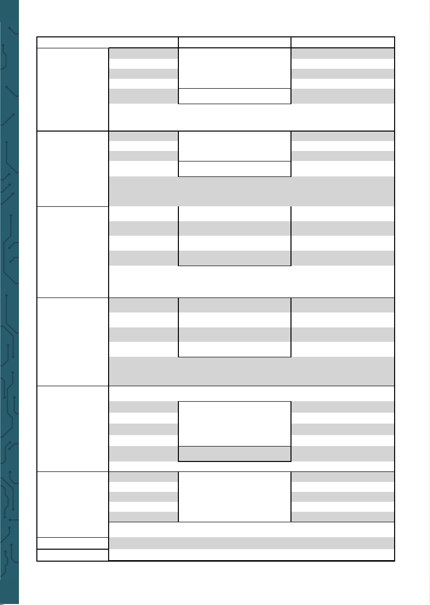
Range Accuracy Resolution
DC Voltage
400.00mV
±(0.8% + 5)
100uV
4.000V 1mV
40.00V 10mV
400.0V 100mV
600.0V
±(1% + 2)
1V
Overload protection:
400mV: 250V, other: 600Vrms.
AC Voltage
4.000V
±(1.2% + 5)
1mV
40.00V 10mV
400.0V 100mV
600.0V
±(1.5% + 5)
1V
Frequency: 40Hz~400Hz;
Frequency of 400V and 600V: 40Hz~100Hz
DC Current
40.00mA
±(1% + 2)
10uA
200.0mA
±(1.5% + 2)
100uA
4.000A
±(1.8% + 2)
1mA
10.00A
±(3% + 2)
10mA
Overload protection:
self restoring fuse: 200mA/250V, 4A and 10A range no fuse.
AC Current
40.00mA
±(1.3% + 2)
10uA
400.0mA
±(1.8% + 2)
100uA
4.000A
±(2% + 3)
1mA
10.00A
±(3% + 5)
10mA
Frequency: 40Hz~400Hz;
self restoring fuse: 200mA/250V, 4A and 10A range no fuse.
Resistance
400.0Ω
±(1% + 3)
0.1Ω
4.000KΩ
±(1.2% + 5)
1Ω
60.00KΩ 10Ω
400.0KΩ 100Ω
4.000MΩ 1KΩ
40.00MΩ
±(1.5%±3)
10KΩ
Overload protection: 220Vrms
Capacity
40.00nF
±(3% + 5)
10pF
400.0nF 100pF
4.000uF 1nF
40.00uF 10nF
100.0uF 100nF
Overload protection: 220Vrms
Diode
0V~1.0V
On-O
<50Ω
Page 7
All specifications herein mentioned apply to the series oscilloscopes. Before
checking an oscilloscope to see if it complies with these specifications, make sure
it meets the following conditions:
The oscilloscope must have been operating continuously for twenty minutes under the specified operating temperature.
The Do Self Cal operation must be performed through the Utility menu if the operating temperature changes by more than 5°C.
The oscilloscope must be within the factory calibration interval.
All specifications are guaranteed unless noted ‘typical’.
This Oscilloscope is a small, lightweight portable instrument which provides the
user with a convenient and easy to operate front panel with which you can perform basic tests.
• General Inspection:
Please check the instrument as following steps aer receiving:
Check the shipping container for damage: Keep the damaged shipping contain-
er or cushioning material until the contents of the shipment have been checked
for completeness and the instrument has been checked mechanically and electrically.
Check the accessories: Accessories supplied with the instrument are listed in
"Accessories" in this manual. If the contents are incomplete or damaged, please
notify the franchiser.
Check the instrument: In case there is any mechanical damage or defect, or the
instrument does not operate properly or fails performance tests, please notify
your reseller.
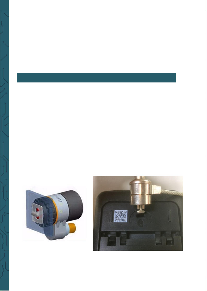
• Use of safety keyhole:
A safety keyhole is reserved on the
back shell of the oscilloscope. Users
need to purchase the safety lock by themselves. Wrap one end of the safety lock
around a hard-to-move object, insert the other end into the safety lock hole, turn
the key clockwise to lock the instrument, and then pull out the key. In this way,
the most basic anti-the requirements can be achieved.
4. GETTING STARTED
Page 8
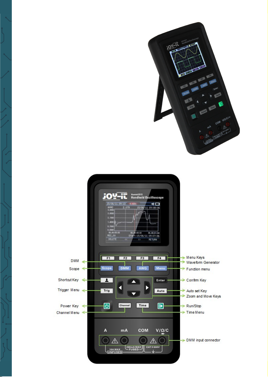
Adjust the bracket
When using the instrument, you can open the
support foot to tilt the instrument upward for
easy operation and observation. When the
instrument is not in use, the user can close the
support foot to facilitate placement or handling.
Aer adjusting the rack, the instrument can be
suspended on the vertical plane.
• Front Panel
The following diagram briefly describes the
front panel of this oscilloscope.
Page 9
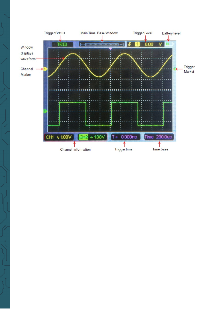
• The user interface
• Functional Check
Follow the steps below to perform a quick functional check to your oscilloscope.
Power
Press the power key and the device starts. Press the power key again, and the de-
vice will shut down. Before starting it, please confirm that the battery has enough
power. The oscilloscope is supplied with a power adapter with USB-Type-C plug.
The input AC power supply is 100~240V, 50~60Hz. The output is 5V@2A. The power
adapter can be used to supply the oscilloscope or charge the battery.
When connect the power adapter to the oscilloscope, if the battery is not installed
inside the oscilloscope, the power key backlight is red and flash; if the battery is
installed inside the oscilloscope and the battery power is not filled, the power key
backlight is red; if the battery is installed inside the oscilloscope and the battery
power is full, the backlight of the source key is extinguishes.
Observe the waveform
1. Set the switch on the probe to 1X and connect the probe to Channel 1 on the
oscilloscope. First, align the slot in the probe connector with the protuberance on
the CH1 BNC and push to connect; then, turn to right to lock the probe in place.
2. If you use the probe hook-tip, the hook end should be removed, the probe pin
should be inserted into the Gen Out output terminal, and the probe grounding
clamp should be clamped on the metal outer ring of the Gen Out output terminal.
Recommended input ~2V@1KHz peak-peak square wave.
Page 10
3. Press the Auto button and you should see within a few seconds a square wave
of about 2V peak-to-peak at 1KHz in the display. Repeat the steps to observe CH2.
• Probe check
Safety
When using the probe, keep your fingers behind the
guard on the probe body to avoid electric shock. Do
not touch metallic portions of the probe head while it
is connected to a voltage source. Connect the probe to
the oscilloscope and connect the ground terminal to
ground before you start any measurements.
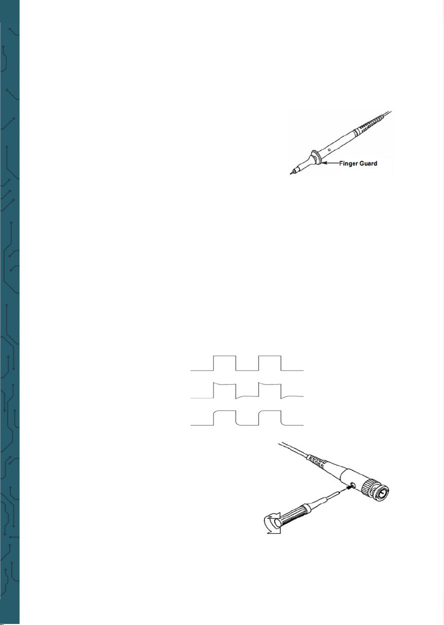
Manual Probe Compensation
Upon the first connection of a probe and an input channel, you should manually
perform this adjustment to match the probe to the input channel. Uncompensated
or wrong compensated probes may lead to errors or faults in measurement. To
adjust the probe compensation, follow the steps below.
1. Press Channel button to enter channel setting menu, Set the Probe option attenuation in the channel menu to 10X. Set the switch on the probe to 10X and connect the probe to Channel 1 on the oscilloscope. If you use the probe hook-tip, the
hook end should be removed, the probe pin should be inserted into the Gen Out
output terminal, and the probe grounding clamp should be clamped on the metal
outer ring of the Gen Out output terminal. The oscilloscope with signal generator
function needs to set output signal as 2V @ 1KHz square wave; The Gen Out terminal of the oscilloscope without signal generator function automatically outputs 2V
@ 1KHz square wave. Press the Auto button.
2. Check the shape of the displayed waveform.
3. If necessary, use a nonmetallic screwdriver
to adjust the variable capacity of your probe
until the shape of the waveform turns to be
the same as the above figure. Repeat this step
as necessary. See the figure below for the way
of adjustment.
Probe Attenuation Setting: Probes are of
various attenuation factors which aect the
vertical scale of the signal. The Probe Check
function is used to verify if the Probe attenuation option matches the attenuation of the probe.
Compensated correctly
Overcompensated
Undercompensated
Page 11
You can press Channel button to enter the channel setting menu and select CH1,
and select the Probe option that matches the attenuation factor of your probe.
Make sure that the Attenuation switch on the
probe matches the Probe option in the oscilloscope. Switch settings are 1X and 10X.
When the Attenuation switch is set to 1X, the
probe limits the bandwidth of the oscilloscope
to 6MHz. To use the full bandwidth of the oscilloscope, be sure to set the switch to 10X.
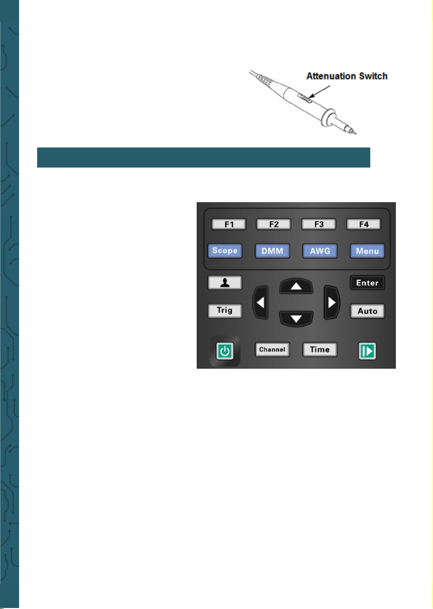
Menu and Control Keys
All the keys are described as follows:
Scope: Oscilloscope mode
DMM:Multimeter mode
AWG:Waveform generator
Menu:Function menu
Trig:Trigger setting menu
Enter: In scope, it saves the user-
defined settings of the oscilloscope;
In generator, press the button to
confirm aer entering the character.
Auto: It adjusts the horizontal and
vertical scales of the oscilloscope
automatically and sets the trigger
coupling, type, position, slope, level
and mode, etc., to acquire a stable waveform display.
Channel: Channel setting menu
Time: Horizontal setting menu
Zoom and move keys:
In the trigger menu, the le and down keys push the trigger level down, and the
right and upper direction keys push the trigger level up;
In the channel menu, the upper and lower direction keys change the zero level position of the channel, and the le and right direction keys change the volt/div of the
channel;
In the time base menu, the upper and lower direction keys change the time/div, and
the le and right direction keys change the horizontal trigger position;
In DMM, switch measurement function;
In generator, aer choosing a parameter, the le and lower direction key will reduce
the parameter value, the right and up direction key will increase the parameter value; it is also used for the digital selection of the virtual keyboard.
5. FUNCTION INTRODUCTION
Page 12
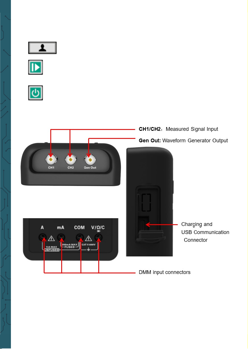
F1/F2/F3/F4: Multi function key, in each menu mode, is responsible for selecting
corresponding menu items in the screen.
• Connectors
Gen Out: The Gen Out terminal of the oscilloscope without signal genera-
tor function always outputs 2V @ 1KHz square wave.
Shortcut keys. Long press this button to enter the menu, and
choose shortcut key function; Aer setting, press this button single time to respond to the corresponding function.
In scope, stop or run the waveform acquisition;
In DMM, hold the measuring data or update data;
In generator, turn on or o the waveform output.
Power key.
Page 13
• Automatic set
Auto set is one of the advantages digital oscilloscopes have. When you push the Auto
button, the oscilloscope will identify the type of waveform (sine or square wave) and
adjust controls according to input signals so that it can accurately display the waveform of the input signal.
The Auto function examines all
channels for signals and displays
corresponding waveforms.
Auto determines the trigger
source according to the following
conditions :
If multiply channels get signals,
the oscilloscope will use the
channel with the lowest frequency signal as the trigger source.
If no signals are found, the oscilloscope will use the lowest-
numbered channel displayed in Auto Scale as the trigger source.
If no signals are found and no channels are displayed, the oscilloscope will display
and use Channel 1 as the trigger source.
• Default settings
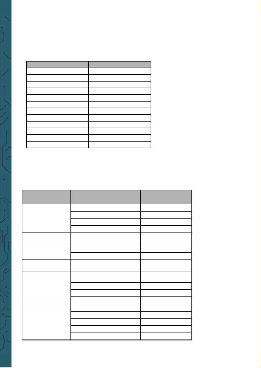
Functions Settings
Cursor O
Display Format Set to YT
Horizontal Position Adjusted
SEC/DIV Adjusted
Trigger Level Set to 50%
Trigger Mode Auto
Trigger Source Adjusted
Trigger Slope Adjusted
Trigger Type Edge
Vertical Bandwidth Full
Vertical Coupling Unchanged
VOLTS/DIV Adjusted
Menu or System
Option, Button or
Knob
Default Setting
Cursor
Type Off
Source CH1
Horizontal (amplitude) ±4div
Vertical (time) ±4div
Display Format YT
Horizontal
Position 0.00s
SEC/DIV 500μs
Measure On or Off Off
Trigger (Edge)
Source CH1
Slope Rising
Mode Auto
Level 0.00v
Vertical System,
All Channels
Bandwidth Limit Unlimited
Coupling AC
Probe Attenuation 1X
Position 0.00div (0.00V)
VOLTS/DIV 1V
Page 14

Long press button, to enter Short key setting menu, and select Default.
Press button, pops up the prompt to recall the default settings on the screen,
now press F1 to confirm. The oscilloscope will display the CH1 waveform and remove
all the others. Press F4 to cancel. The table below gives the options, buttons and controls that change settings at default setup.
The following settings do not change when you recall default settings:
Language options, saved settings, saved waveforms, saved reference waveforms,
calibration data.
• Horizontal System
Press Time button to enter horizontal system menu, use the direction keys to change
the horizontal scale (time base) and the horizontal trigger position. When you change
the horizontal scale, the waveform will expand or contract to the screen center.
1. SEC/DIV Knob: Used to change the horizontal time scale to magnify or compress
the waveform horizontally. If the waveform acquisition is stopped (by using button),
press Time button and Up or Down buttons to expand or compress the waveform.
2. Horizontal Position Knob: Used to control the trigger position against the screen
center. Press Time button and Right or Le buttons to move the waveform right or
le. The key resolution vary according to time base. Press "AUTO" key can make the
horizontal position return to zero.
3. Mode: Y-T, X-Y, Roll, Scan.
Y-T: YT format shows the vertical voltage in relation to time (horizontal scale). Press
Time->Mode to set.
X-Y: The XY mode is used to analyze phase dierences, such as those represented by
Lissajous patterns. The format plots the voltage on CH1 against the voltage on CH2,
where CH1 is the horizontal axis and CH2 is the vertical axis. You may view the same
waveform in XY mode. To perform this operation, stop the acquisition and press Time
->Mode to change the display mode to X-Y.
Roll: In Roll mode, the waveform display rolls from right to le. Trigger or horizontal
oset control of waveforms is available during Roll Mode, and it’s only available when
set to 100ms/div or slower. Press Time->Mode to change the display mode to Roll, the
time/div will be changed to 100ms/div automatically.
Scan: In Scan Mode, the waveform display scan updates from le to right. In Scan
mode, trigger and horizontal oset control of waveforms are available during Scan
Mode. This mode is only available when set to 100ms/div or slower. Generally, used
for measuring low frequency signal. When the time/div is 100ms/div or slower, the
oscilloscope automatically enters the scan mode.
Page 15
Vertical System
Vertical system can be used to adjust the vertical scale and location and other settings of the channel. Each channel has a separate vertical menu, and each channel
can be set separately.
1.Vertical Position
Press Channel->F1 to select the channel, and press Up or Down direction keys to
move the vertical position of the selected channel.
2. VOLTS/DIV Settings
The range of Volt/div is 10mV/div-10V/div (1X), or 100mV/div-100V/div (10X), 1V/div1000V/div (100X), step by 1-2-5. Press Channel->F1 to select the channel, and press
Right or Le direction keys to change the Volt/div of the selected channel.
3. Channel Setting Menu
• Trigger System
The trigger determines when the oscilloscope begins to acquire data and display a
waveform. Once a trigger is properly set up, the oscilloscope can convert unstable
displays or blank screens to meaningful waveforms.
The triggering mode of this series oscilloscope is edge trigger.
Edge trigger distinguishes the trigger points by seeking the specified edge (rising,
falling, rising & falling) and trigger level.
Press Trig button to enter trigger menu.
Trigger Source: Select the trigger source signal to CH1 or CH2. You can use the trigger source options to select the signal that the oscilloscope uses as a trigger.
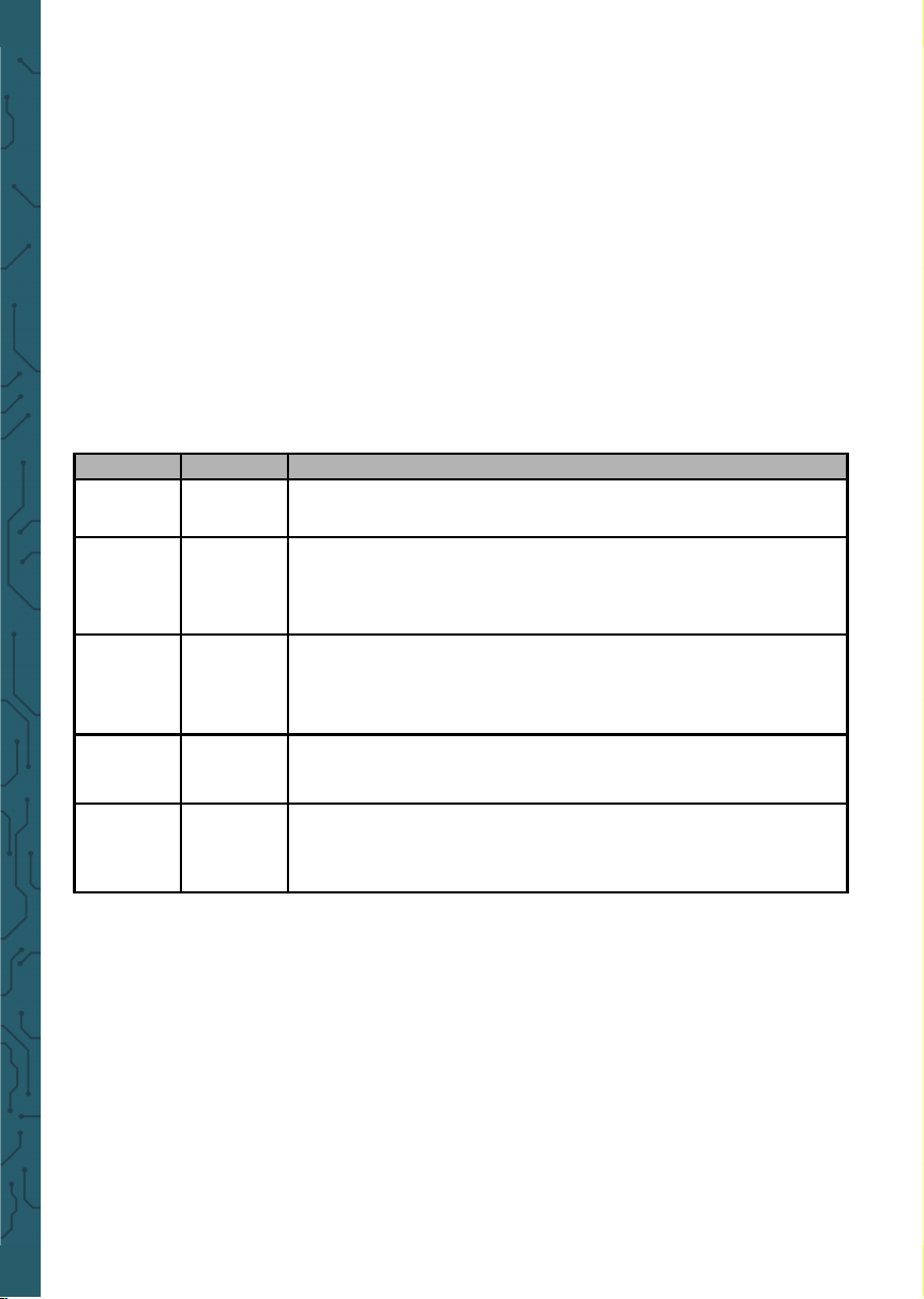
Options Settings Comments
On/O
On
O
Turn on the waveform display.
Turn o the waveform display.
Coupling
DC
AC
GND
DC passes both DC and AC components of the input signal.
AC blocks the DC component of the input signal and attenuates signals below 10Hz.
GND disconnects the input signal.
Probe
1X
10X
100X
1000X
Selects a value according to the probe attenuation factor so
as to ensure correct vertical readouts.
Reduce bandwidth to 6MHz when using a 1X probe.
BW
Limit
On
O
Limits the bandwidth to reduce display noise; filters the
signal to eliminate noise and other unnecessary HF compo-
nents.
Invert
On
O
The invert function turns the displayed waveform 180 degrees, with respect to the ground level. When the oscilloscope is triggered on the inverted signal, the trigger is also
inverted.
Page 16
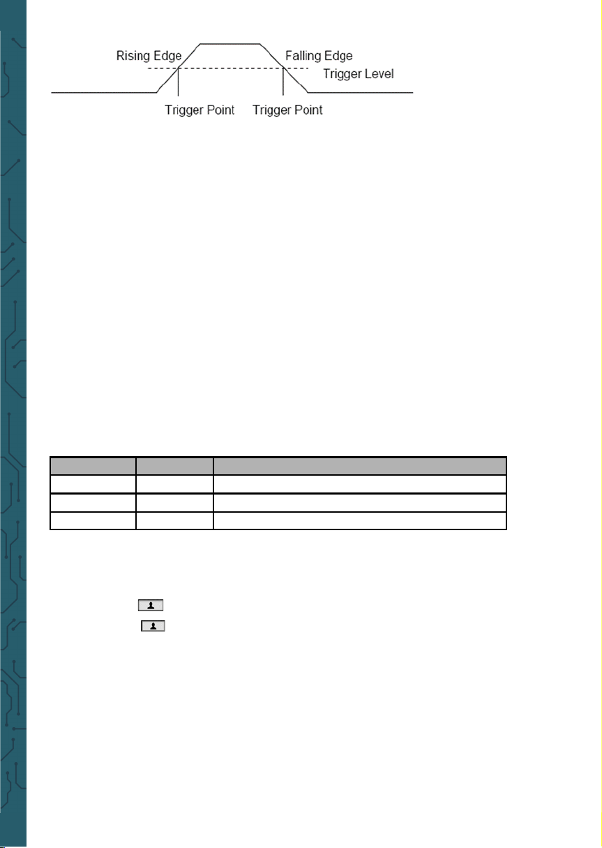
Slope: Select the
trigger slope to rising,
falling, rising &
falling.
Trigger Mode: You can select the Auto or Normal mode to define how the oscilloscope acquires data when it does not detect a trigger condition. Auto Mode performs the acquisition freely in absence of valid trigger. It allows the generation of
untriggered waveforms with the time base set to 100ms/div or slower. Normal Mode
updates the displayed waveforms only when the oscilloscope detects a valid trigger
condition. Before this update, the oscilloscope still displays the old waveforms. This
mode shall be used when you only want to view the eectively triggered waveforms. In this mode, the oscilloscope displays waveforms only aer the first trigger.
To perform single trigger acquisition, the trigger mode can be set to "single". When
triggered, a single waveform is acquired and then stop.
Force Trigger: Used to complete an acquisition regardless of an adequate trigger
signal. This button becomes useless if the acquisition is already stopped.
Trigger Level: It sets the amplitude level the signal must cross to cause an acquisition when using the Edge or Pulse Width trigger. Press Trig button to enter, and press
Up or Down direction keys to change the trigger level.
• Save Waveforms
Press Menu button to enter, and select Save to enter store waveform menu. The
waveform can be saved to the oscilloscope inside, also can be recalled to view.
The Save Menu Table:
To save the waveform, follow these steps:
1. Press F1 to select the storage position of the waveform.
2. Press F2 to save the waveform data to the specified position. Also, users can long
press button to enter, and select F4->F2 (Data Save) as shortcut keys.
Press button one time to save the current waveform data.
3. Press F3, to recall the saved waveform. The waveform can be enlarged or reduced
in the Channel or Time menu by using the direction keys.
Attention:
1. Waveform storage can not only save the waveform of the current channel, but
also save the current state settings at the same time.
2. Users can permanently store 6 waveforms in the oscilloscope memory and rewrite
them at any time.
Menu Setting Description
Position 1,2,3,4,5,6 Select the internal storage position.
Save Save waveform data.
Recall
Recall the waveform.
Page 17
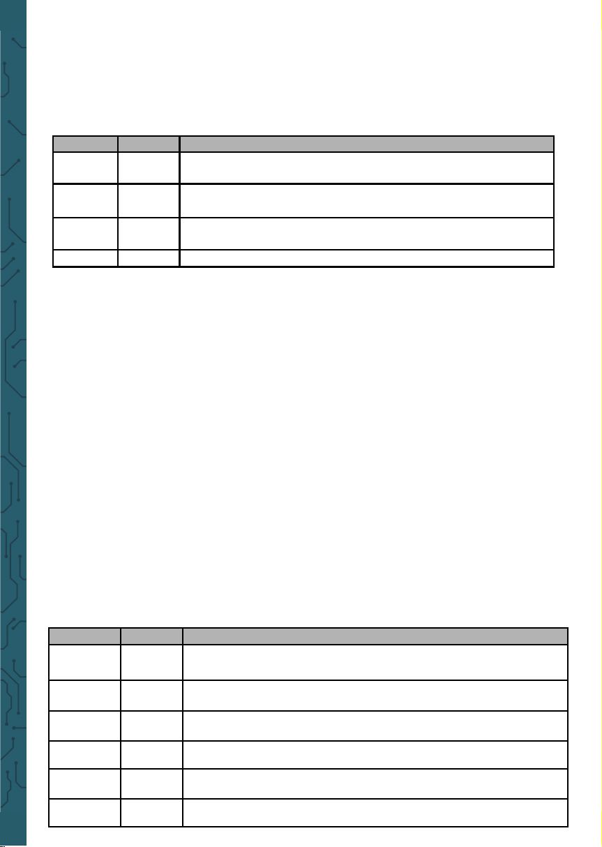
Reference Waveform
The REF channel is used to display the reference waveform, which can compare the
actual waveforms with the reference waveforms to find out the dierences.
Press Menu button to enter, and select Ref to enter reference Waveform menu.
REF Menu Table:
To save the reference waveform, follow these steps:
Press F1 to select the position of the reference waveform.
Press F2 to open the REF channel.
Press F3 to select the source to CH1 (or CH2), and only select the open channel.
Press F4 to save the current waveform to the specified location.
• Measurement
Scale measurement
Graticule: This method allows you to make a quick, visual estimate and take a simp-
le measurement through the graticule divisions and the scale factor.
For example, you can take simple measurements by counting the major and minor
graticule divisions involved and multiplying by the scale factor. If you counted 6 major vertical graticule divisions between the minimum and maximum values of a waveform and knew you had a scale factor of 50mV/division, you could easily calculate
your peak-to-peak voltage as follows: 6 divisions x 50mV/division = 300mV.
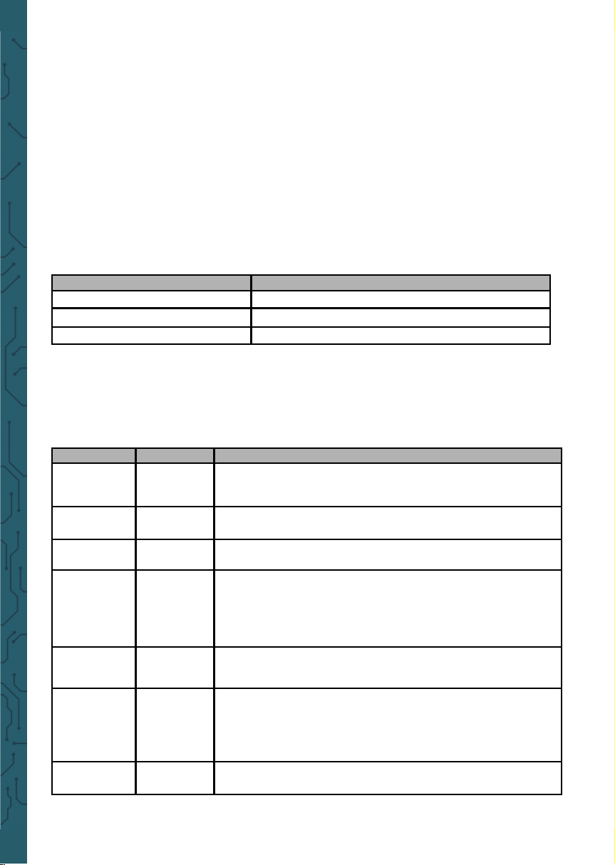
Cursor measurement
The cursor measurement has two parallel lines on the screen, and move two lines to
measure the time and voltage parameters of the input signal. The result of cursor
measurement will be displayed on the second page of the cursor menu. Before use
cursor measurement, make sure that the measured source is the signal you need to
measure.
Press Menu button to enter, and select Cursor to enter cursor measurement.
Menu Setting Description
Position
Ref-A
The REF waveform is saved to the oscilloscope Ref-A or Ref-B.
Enable
On
O
Open the REF waveform.
Close the REF waveform.
Source
CH1
CH2
Select CH1 to save as a REF waveform.
Select CH2 to save as a REF waveform
Save Save the REF waveform.
Menu Setting Description
Enable
On
O
Open the cursor measurement.
Close the cursor measurement.
Type
Voltage
Time
The horizontal line is shown to measure the voltage parameters. The vertical line is shown to measure the time parameters.
Source
CH1
CH2
Select the measured source.
Cursor1
Select Cursor1 and press up, down, le and right keys to move
the Cursor1 position, and display the Cursor1 value.
Cursor2
Select Cursor2 and press up, down, le and right keys to move
the Cursor2 position, and display the Cursor2 value.
Incre-
ment
The dierence between the Cursor1 and the Cursor2.
Page 18
To do cursor measurement, follow these steps:
1. Press F1 to open the cursor measurement;
2. Press F2 to select a type of cursor measurement.
3. Press F3 to select the channel that needs to be measured.
4. Press F4 to enter the second page, press F1 or F2 to select Cursor1 or Cursor2, press
up, down, le and right to move Cursor1 or Cursor1;
5. The result of cursor measurement will be displayed on the cursor menu.
Automatic Measurement
The oscilloscope provides 2 kinds of automatic measurements, including frequency
and amplitude.
Press Menu button to enter, select Measure to enter automatic measurement. Press
F1 to open, the measurement results will be displayed in the top le corner of the
screen.
Attention:
In the measurement result, the yellow font is the result of CH1, and the green font is
the result of CH2.
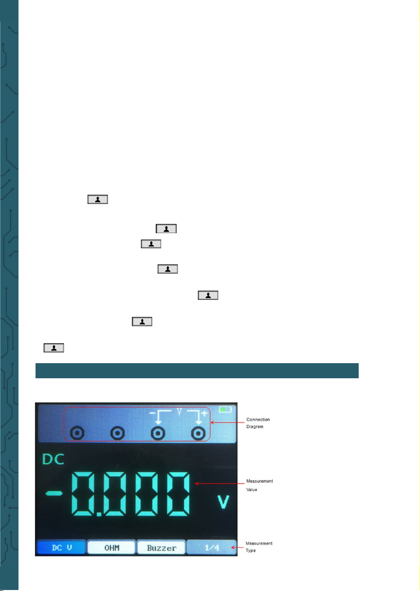
• Utility
Press Menu Button to enter.
Menu Description
Frequency
Measure the frequency of the signal.
Maximum Voltage
Measure the maximum voltage of the signal.
Minimum Voltage
Measure the minimum voltage of the signal.
Menu Setting Description
Language
German
English
Set the menu language.
Sound
On
O
Open the key sound.
Close the key sound.
Backlight
luminance
1~10 Set backlight brightness of the screen.
Backlight
time
30s
60s
90s
120s
Unlimited
Set the screen backlight time.
System
infor-
mation
Display system information, such as soware version or
PCB version.
Automatic
shutdown
5 Minute
10 Minute
20 Minute
30 Minute
Unlimited
Set automatic shutdown time.
Calibration
Start
Return
Start the self calibration.
Exit the self calibration.
Page 19
Note:
1. Backlight time and automatic shutdown time will not be executed when the oscilloscope is plugged in with an external charging device or connected to a computer via a USB cable.
2. Shutdown automatically saves last setup.
Self calibration
The self calibration routine helps optimize the oscilloscope signal path for maximum measurement accuracy. You can run the routine at any time but should always run it if the ambient temperature changes by 5°C or more. For a more accurate calibration, please power on the oscilloscope and wait for 20 minutes until it
has adequately warmed up.
To do self calibration, follow these steps:
1. Ensure that no input signal is input, otherwise it may damage the instrument.
2. Press Menu button to select the self calibration function.
Shortcut key
Long press button to enter shortcut key settings menu, and choose shortcut
key function; Aer setting, press this button single time to respond to the corresponding function.
Default settings: Long press button to enter, and select F1 (Default) as the
shortcut key, then press button one time and select F1 TO confirm to recall
the default settings
Custom settings: Long press button to enter, and select F2 or F3 (custom 1 or
2) as shortcut keys. Now press Enter button and click F1 to confirm to save the current settings to custom settings. Press button one time and click F1 to con-
firm to recall the custom settings.
Save data: Long press button to enter, and select F4->F1 (Data Save) as
shortcut keys. Press Menu -> Save to enter the save menu, select a location, press
button one time to save the current waveform data.
Interface
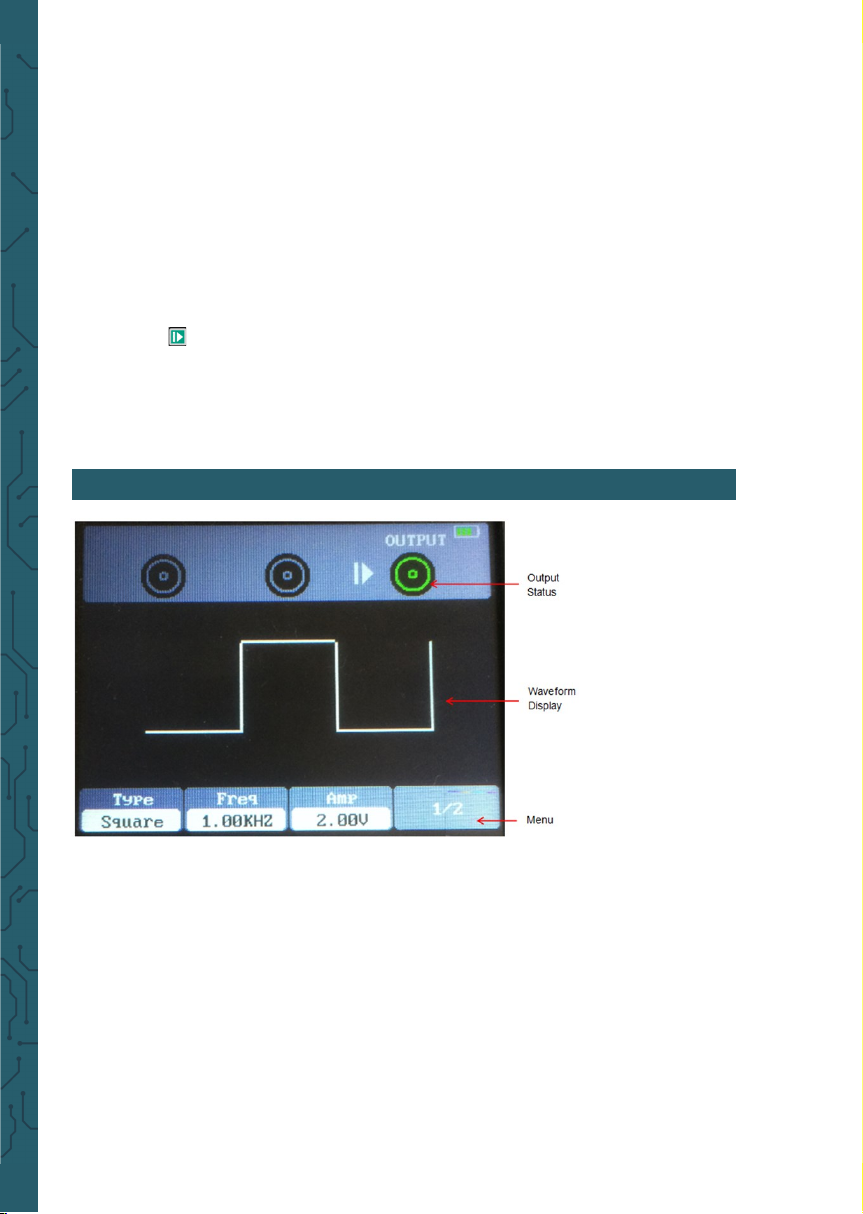
This chapter introduces
the multimeter function.
The measuring types
include DC voltage (V,
mV), AC voltage, DC current (A, mA), AC current
(A, mA), resistance, capacitance, diode, and on
-o test.
6. DIGITAL MULTIMETER
Page 20

Measurement
1. DC and AC voltage measurement
Press the power button to turn on, then press the "DMM" button to enter to the multi
meter function interface;
Press the up, down, le and right direction keys or F1, F2, F3, F4 multi-function keys
to select "DC V", "DC mV" or "AC V";
Insert the black pen into the input port of the COM banana socket, and insert the red
pen into the input port of the V/Ω/C banana port;
Connect the red and black forms to the measured point. The voltage value of the
measured point will be displayed on the screen.
2. DC and AC current measurement
Press the power button to turn on, then press the "DMM" button to enter to the multi
meter function interface;
To measure the DC current greater than 200mA, press the up, down, le and right
keys or F1, F2, F3, F4 multi function keys to select "DC A" or "AC A", and insert the
black pen to the input end of the COM banana socket, and insert the red pen into the
input port of the “A” banana socket;
To measure the DC current less than 200mA, press the up, down, le and right keys
or F1, F2, F3, F4 multi function keys to select "DC mA" or "AC mA", and insert the
black pen to the input end of the COM banana socket, and insert the red pen into the
input port of the “mA” banana socket.;
Connect the red and black forms to the measured point. The current value of the
measured point will be displayed on the screen.
3. Resistance measurement
Press the power button to turn on, then press the "DMM" button to enter to the multi
meter function interface;
Press the up, down, le and right direction keys or F1, F2, F3, F4 multi-function keys
to select "OHM";
Insert the black pen into the input port of the COM banana socket, and insert the red
pen into the input port of the V/Ω/C banana port;
Connect the red and black forms to the measured point. The resistance value of the
measured point will be displayed on the screen.
4. Capacity measurement
Press the power button to turn on, then press the "DMM" button to enter to the multi
meter function interface;
Press the up, down, le and right direction keys or F1, F2, F3, F4 multi-function keys
to select " ";
Insert the black pen into the input port of the COM banana socket, and insert the red
pen into the input port of the V/Ω/C banana port;
Connect the red and black forms to the measured point. The capacitance value of
the measured point will be displayed on the screen.
5. Diode measurement
Press the power button to turn on, then press the "DMM" button to enter to the multi
meter function interface;
Press the up, down, le and right direction keys or F1, F2, F3, F4 multi-function keys
to select " ";
Insert the black pen into the input port of the COM banana socket, and insert the red
pen into the input port of the V/Ω/C banana port;
Connect the red and black forms to the measured point. The diode value of the mea-
Page 21
sured point will be displayed on the screen.
6. Buzzer measurement
Press the power button to turn on, then press the "DMM" button to enter to the multi
meter function interface;
Press the up, down, le and right direction keys or F1, F2, F3, F4 multi-function keys
to select "Buzzer";
Insert the black pen into the input port of the COM banana socket, and insert the red
pen into the input port of the V/Ω/C banana port;
Connect the red and black forms to the measured point. If the resistance of the measured point is less than 50 ohms, the instrument will emit "drop" sound.
7. Data hold function
Press the button on the instrument, and the displayed data will hold on the display, even if the input signal changes or eliminates, the value will not change.
Note: Please select the required measuring gear correctly and then measure again.
This chapter introduces
the function of waveform generator.
Operation description
Press the power button
to turn on, and then
press the "AWG" button
to enter the waveform
generator function interface.
1. Set type
Press F1 button to select the desired signal waveform, the optional waveform type
includes square, triangle, sine, trapezoidal and four arbitrary.
2. Set frequency
Press F2 button to select Frequency, then use the up, down, le and right direction
keys to adjust the frequency, press F2 button to open the digital keyboard again, use
the up, down, le, right direction keys and Enter key to set frequency parameter,
select "OK" and press Enter button to confirm.
3. Set amplitude
Press F3 button to select Amplitude, then use the up, down, le and right direction
keys to adjust the frequency, press F3 button to open the digital keyboard again, use
the up, down, le, right direction keys and Enter key to set frequency parameter,
select "OK" and press Enter button to confirm.
7. SIGNAL GENERATOR
Page 22

Note that the entered voltage is the half of the peak-to-peak voltage.
4. Set oset
Press F4 button to enter the second page. Press F2 to select Oset, then use the up,
down, le and right direction keys to adjust the frequency, press F2 button to open
the digital keyboard again, use the up, down, le, right direction keys and "Enter"
key to set frequency parameter, select "OK" and press Enter button to confirm.
5. Set duty cycle
Enter the second page. Press F3 to select Duty, then use the up, down, le and right
direction keys to adjust the frequency, press F3 button to open the digital keyboard
again, use the up, down, le, right direction keys and Enter key to set frequency parameter, select "OK" and press Enter button to confirm.
6. Generate an arbitrary waveform
It is necessary to edit the arbitrary waveform in connection with the soware and
download it into the machine. There are 4 arbitrary wave positions, and each position can permanently store an arbitrary wave.
7. Aer setting the waveform parameters, press the button to turn on or o the
signal output. The output waveform of the signal generator can be observed through
an oscilloscope.
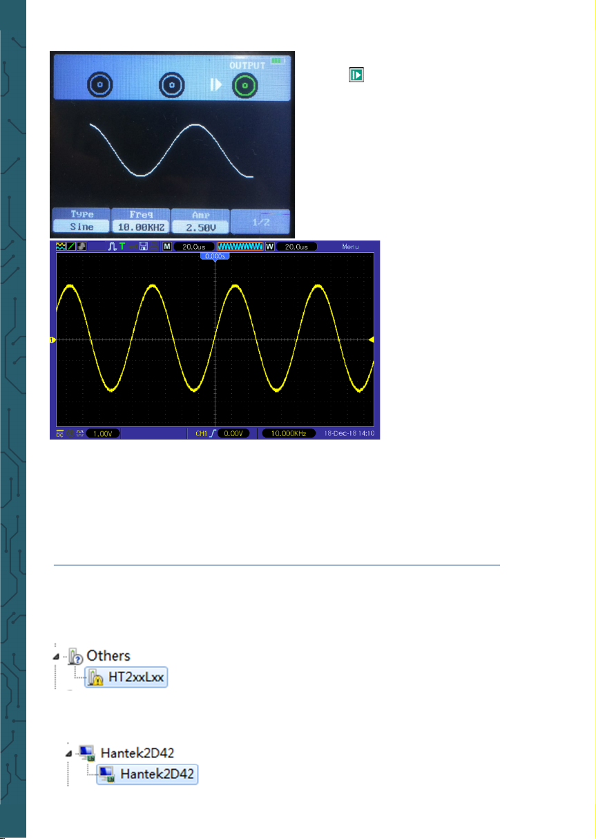
• Output the sine waveform
Output a sine waveform with 10KHz/2.5Vpp as follows:
1.Press AWG button to enter the waveform generator function interface.
2.Press F1 to select “Sine”
3. Frequency: First press F2 button to select Frequency, then use the up, down, le
and right direction keys to adjust the frequency. Second, press F2 button to open
the digital keyboard again, use the up, down, le, right direction keys and "Enter"
key to set frequency parameter, select "OK" and press Enter button to confirm. Set
the frequency to 10KHz
4. Amplitude: First press F3 button to select Amplitude, then use the up, down, le
and right direction keys to adjust the amplitude. Second, press F3 button to open
the digital keyboard again, use the up, down, le, right direction keys and Enter key
to set amplitude parameter, select "OK" and press Enter button to confirm. Set the
amplitude to 2.5V
5. Oset: Press F4 to enter the second page. First press F1 button to select Oset, then use the up, down, le and right direction keys to adjust the oset.
Second, press F1 button to open the digital keyboard again, use the up, down,
le, right direction keys and "Enter" key to set oset parameter, select "OK"
Page 23
and press Enter button to confirm.
6. Press button, the backlight of
the button turns green, i.e. output
sine waveform.
7. The waveform observed by an oscilloscope is
as follows:
• Output the arb waveform
1. Install the soware
Download the latest soware on the oicial website, double click Setup.exe to install.
The link is as follows:
https://joy-it.net/files/files/Produkte/JT-DMSO2D72/DMSO2D72_Soware.zip
2. Install the driver
Connect the oscilloscope to the computer via the USB cable. Open the device manager
of the computer and find the device. If the device icon is shown in the following pic-
ture, you need to install the driver manually.
The drivers are located in the soware package in the Driver folder.
Right click the device, and select “Update the driver soware”, and select the driver
files path to install.
Aer successful installation of the driver, it is shown as
follows:
Page 24
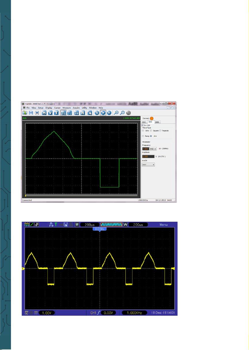
3.Double-click the Hantek2xx2 icon to open the soware and select "DDS" in the
right control bar to enter the signal generator control bar.
4. Put "√" in the box in front of "on/o" to open the signal output.
5. Select "signal type" as "arb", and set the corresponding frequency and amplitude.
6. Select "Arb Channel" as Arb1/Arb2/Arb3/Arb4. Each arb channel can save only one
arbitrary waveform which was downloaded last time. Turn on again aer shutdown,
and automatically recall.
7. Draw arbitrary waves in waveform area with mouse.
8. Connect Gen Out connector to oscilloscope for observation.
Page 25
When the battery on the screen is displayed as blank, it indicates that the battery is
about to run out. When the battery power is too low, the oscilloscope will prompt
“Power o aer 5s”. In order to avoid the automatic shutdown of the oscilloscope
due to insuicient power supply, please charge it in time.
If the power button is pressed, the oscilloscope will not react, indicating that the
battery power may be exhausted.
You can charge the oscilloscope in the following way:
Charge the oscilloscope through charger: Connect the oscilloscope to the power
socket through the USB data line and charger distributed by the instrument for
charging.
Charge the oscilloscope through the USB interface: Connect the oscilloscope to a
computer or other equipment through the USB data line.
When charging, turn on the oscilloscope and the battery frame on the screen will
change.
When the battery is full, the oscilloscope will automatically stop charging.
• Storage and Replacement of the battery
Storage
Lithium batteries must be stored in clean, dry and ventilated rooms. Contact with
corrosive substances should be avoided and the have to be kept away from fire and
heat sources.
If the lithium battery is not used for a long time (for example, more than 6 months),
it should be charged with 50%-70% electricity, and removed from the instrument,
and stored in a dry and cool environment.
If the lithium battery rusts, leaks, bulges and other phenomena, it should be removed immediately and scrapped.
Replacement
Batteries can be recharged repeatedly, but
they are vulnerable to wear and tear. If
standby time is found to be greatly reduced, batteries need to be replaced.
The battery specification is 18650 lithium
battery, 3.7V, 2600mA.
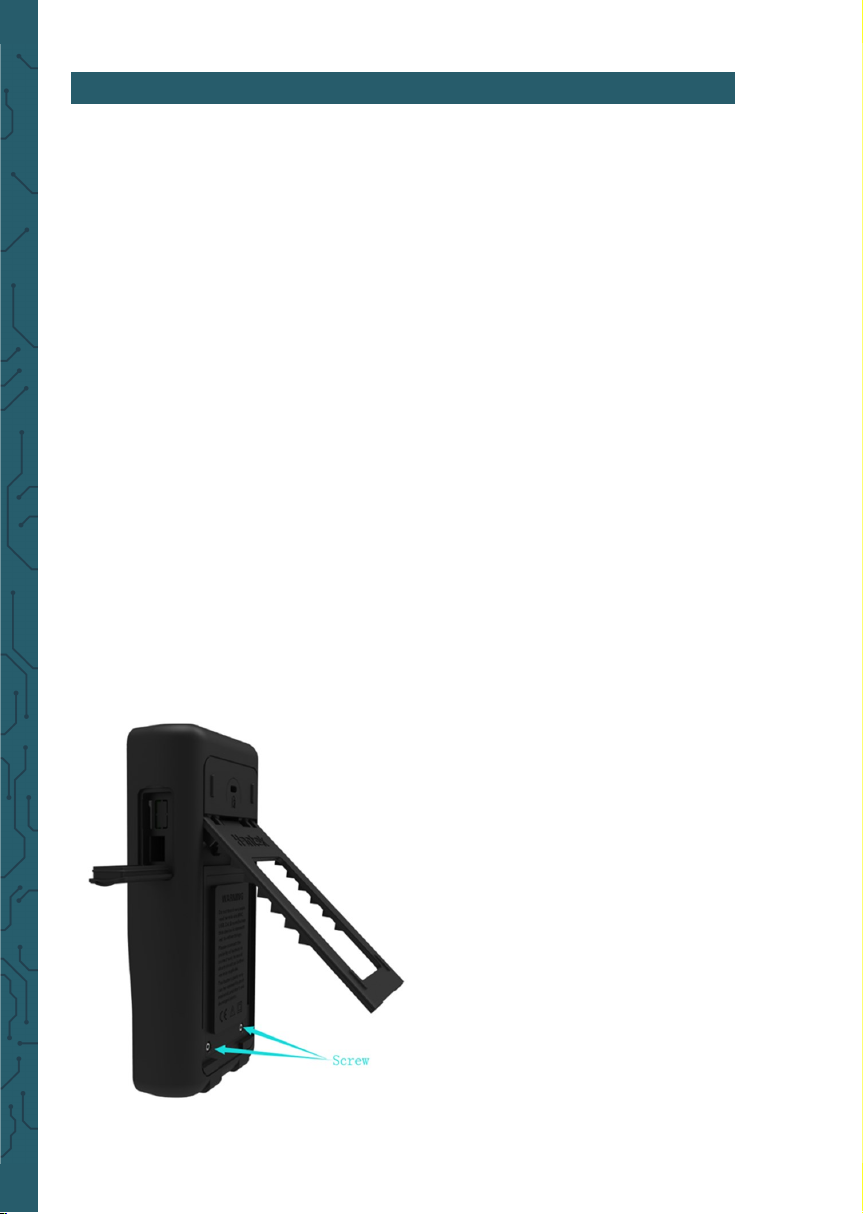
Please refer to the following to replace it.
Unfold the supporting leg, there are two
screws. Remove the screws and remove the
battery cover, you will see the batteries.
Now you can remove the battery and re-
place.
Attention: Pay attention to the positive
and negative poles of batteries when replacing baterries.
8. CHARGE
Page 26

1. If the oscilloscope does not start up at power on, follow these steps:
Check whether the battery is installed and confirm whether the battery level is
enough.
If the battery level is not enough, use the power adapter to charge.
Restart the instrument aer the battery level is enough.
Contact your local distributor or directly keep touch with Joy-IT Support depart-
ment if the oscilloscope still can not be turned on normally.
2. If there is no display of waveforms on the screen when the oscilloscope is
turned on, follow these steps:
Check the probe to assure its proper connection to the input BNC.
Check the channel switch (Channel button) to make sure it has been turned on.
Check the input signal to verify it has been connected to the probe correctly.
Airm that all measured circuits have signals to output.
Turn up the magnitude for DC signals with large magnitude.
In addition, you may press the Auto button to perform an automatic detection of
signals at first.
Contact Joy-IT Technical Support department in time if there is still no display of
waveforms.
3. If the waveform of the input signal is distorted seriously, follow these steps:
Check the probe to assure its proper connection to the channel BNC.
Check the probe to assure its good connection to the measured object.
Check the probe to verify it has been well calibrated.
Otherwise, refer to the content about calibration described in this manual.
4. If the waveform is rolling continuously on the screen but can not be triggered, follow these steps:
Check the trigger source to make sure it consistent with the input channel.
Check the trigger level to assure its correct adjustment.
You may press TRIGGER button to enter trigger menu, and use Up, Down, Right, Le
direction keys to adjust trigger level to return to signal.
9. TROUBLESHOOTING
Page 27

General Care
Do not put or leave the device in a place where the LCD display will be exposed to
direct sunlight for long periods of time.
Note: To avoid damage to the oscilloscope or probes, do not expose them to sprays,
liquids, or solvents.
Cleaning
Examine the oscilloscope and probes as oen as operating conditions require. To
clean the exterior surface, perform the following steps:
Use a lint-free cloth to remove floating dust on the outside of the oscilloscope and
probes. Take care to avoid scratching the display.
Use a so cloth dampened with water to clean the oscilloscope. For more eicient
cleaning, you may use an aqueous solution of 75% isopropyl alcohol.
Note: To avoid damage to the surface of the oscilloscope or probes, do not use any
corrosive or chemical cleaning agents.
All specifications herein mentioned apply to the series oscilloscopes. Before checking an oscilloscope to see if it complies with these specifications, make sure it meets
the following conditions:
The oscilloscope must have been operating continuously for twenty minutes under
the specified operating temperature.
The Do Self Cal operation must be performed through the Utility menu if the operat-
ing temperature changes by more than 5°C.
The oscilloscope must be within the factory calibration interval.
All specifications are guaranteed unless noted ‘typical’.
All the following accessories are available by contacting your local Distributor.
• 1x Passive probe oscilloscope (1:1) / (1:10)
• 1x Power adapter
• 1x USB-A-to-USB-C cable
• 1x BNC-to-Crocodile clip cable
• 2x Test prod cable multimeter
10. GENERAL CARE AND CLEANING
11. DISCLAIMER OF TECHNICAL SPECIFICATIONS
12. ACCESSORIES
Page 28

www.joy-it.net
Pascalstr. 8 47506 Neukirchen-Vluyn
14. SUPPORT
If there are still any issues pending or problems arising aer your purchase, we
are available for you by e-mail, telephone and with our ticket support system.
E-Mail: [email protected]
Ticket system: http://support.joy-it.net
Telephone: +49 (0)2845 98469-66 (10-17 o‘clock)
For further information please visit our website:
www.joy-it.net
13. PRODUCT RECYCLING
Our informaon and take-back obligaons according to the Electrical and
Electronic Equipment Act (ElektroG)
Symbol on electrical and electronic equipment:
2
This crossed-out dustbin means that electrical and electronic appliances do not
belong in the household waste. You must return the old appliances to a collecon point. Before handing over waste baeries and accumulators that are not
enclosed by waste equipment must be separated from it.
Return opons: As an end user, you can return your old device (which essenally
performs the same funcon as the new device purchased from us) for disposal
free of charge when you purchase a new device. Small appliances with no exter-
nal dimensions greater than 25 cm can be disposed of in normal household
quanes independently of the purchase of a new appliance.
Possibility of return at our company locaon during opening hours: Simac GmbH,
Pascalstr. 8, D-47506 Neukirchen-Vluyn, Germany
Possibility of return in your area: We will send you a parcel stamp with which you
can return the device to us free of charge. Please contact us by e-mail at
Service@joy-it.net or by telephone.
Informaon on packaging: Please pack your old appliance safely for transport, if
you do not have suitable packaging material or do not wish to use your own,
please contact us and we will send you suitable packaging.
 Loading...