

Page 1
Joyce/Dayton Corp
Operation and Maintenance Manual for
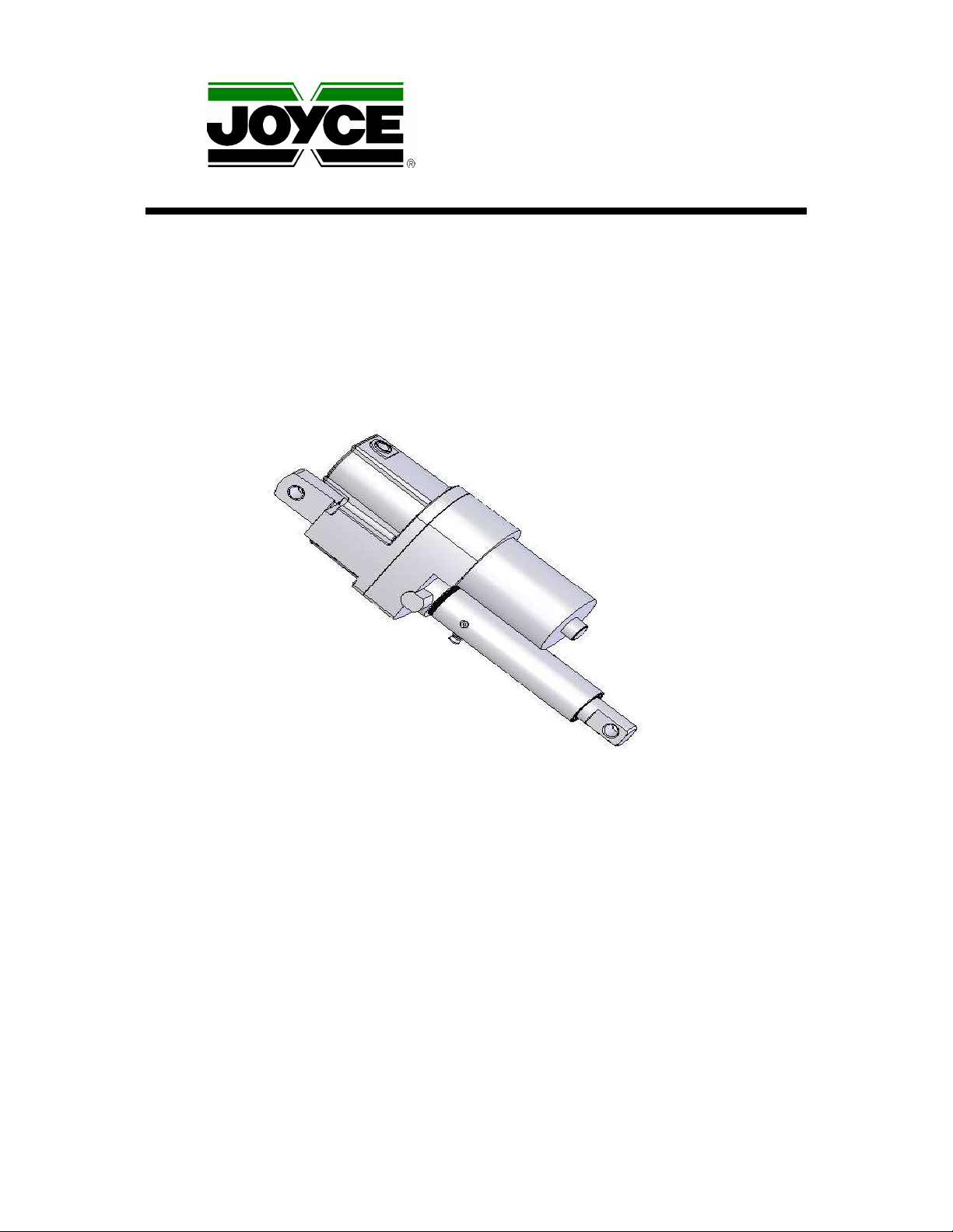
Joyce/Dayton Linear Actuator
1500 Pound Capacity AC Actuator (with limit switch and potentiometer)
.
WARNING !
The recommendations in this manual for installation, operation and maintenance must be followed to
ensure safe use. All persons responsible for the installation and use of Joyce/Dayton Linear Actuators
must be familiar with the contents of this manual.
Customer is responsible for guards and other protective devices and ensuring that Linear Actuator
usage conforms with local and national operating and safety codes appropriate to the class of
equipment into which the Linear Actuator is installed.
©2006 Joyce/Dayton Corp. All rights reserved FB0188A 11/06
Page 2

2
Table of Contents
Section I – General Information
1-2 Purpose and Scope...........................................................................3
1-3 Receipt of Product.............................................................................3
1-4 Warranty...............................................................................................3
1-5 Precautions for Use...........................................................................3
1-6 General Installation Instructions....................................................4
1-7 Limit Switch Adjustment - Initial ....................................................4
1-8 Limit Switch Adjustment – Fine......................................................5
1-9 Final Installation of Actuator...........................................................5
Section II – Maintenance
2-1 Lubrication...........................................................................................6
2-2 Repair Parts.........................................................................................6
2-3 Disassembly of Linear Actuator.....................................................7
2-4 Assembly of Linear Actuator ..........................................................7
Section III – Views and Parts Lists
3-1 Exploded View....................................................................................9
3-2 Parts List for Linear Actuator..........................................................10
Section IV – Technical Drawings and Illustrations
4-1 Wiring Diagram...................................................................................11
4-2 Limit Switch.........................................................................................11
4-3 Brake Assembly Diagram................................................................12
4-4 Travel Limit Chart...............................................................................12
Section V – Part Numbers and Ordering
5-2 Record of maintenance ....................................................................14
1-1 Contacting Joyce Dayton.................................................................3
5-1 Ordering information.........................................................................13
Page 3

3
Section I
General Information
1-1 Contacting Joyce/Dayton Corp.
Joyce/Dayton Corp.
P.O. Box 1630
Dayton, OH 45401
(800) 523-5204 (US and Canada only)
(937) 294-6261 (937) 297-7173 Fax
Email: [email protected]
Website: www.joycedayton.com
1-2 Purpose and Scope
This manual provides installation, operation and maintenance instruction for the standard 1500
pound capacity Joyce/Dayton Linear Actuator. Although this manual covers the standard Linear
Actuators, some may vary significantly from this manual. For special units not covered, please
contact Joyce/Dayton Corp. for assistance.
1-3 Receipt of Product
All equipment should be immediately inspected upon receipt for any damage and to verify correct
product and quantities. Any problems should be reported to Joyce/Dayton Corp. and the freight
carrier as soon as possible. Products returned without a Return Goods Authorization (RGA) form
will not be accepted.
1-4 Warranty
Seller warrants its products to be free from defects in material and workmanship under normal
and proper use in accordance with instruction of seller for a period of one year from the date of
shipment to buyer. Seller's liability under such warranty or in connection with any other claim
relating to the products shall be limited to the repair, or at seller’s option, the replacement or
refund of the purchase price, of any products or parts or components thereof which are returned
to seller freight prepaid and which are defective in material or workmanship. Products or parts or
components thereof which are repaired or replaced by seller will be returned to buyer freight
collect. This warranty is not intended to cover consumer products, as defined in the MagnusonMoss Warranty-Federal Trade Commission Improvement Act, 15 U. S. C. Sections 2301-12,
which are purchased by buyer for purposes other than resale. If buyer is not intending to resell the
products, and if the products are consumer products as defined in the Magnuson-Moss Act, the
foregoing warranty, but not the limitation of seller's liability, shall be null and void. EXCEPT AS
EXPRESSLY STATED ABOVE, SELLER MAKES NO WARRANTY, EXPRESS OR IMPLIED,
WHETHER OF MERCHANTABILITY OR FITNESS FOR ANY PARTICULAR PURPOSE OR
USE OR OTHERWISE, ON THE PRODUCTS, OR ON ANY PARTS OR LABOR FURNISHED
DURING THE SALE, DELIVERY OR SERVICING OF THE PRODUCTS.
1-5 Precautions of Use and Installation
1. Travel is limited using the limit switches provided. It is imperative that the limit switches be set
within the designed limits of the Linear Actuator. Exceeding the design limits can cause
damage to the internal linear actuator mechanism. Follow the procedure in Sections 1-7 and 18 of this manual.
2. In most applications, factory or manufacturer-assisted installation is not required. However, it is
necessary that appropriate, qualified personnel perform the installation of Joyce/Dayton
products.
3. Joyce/Dayton Linear Actuators are not rated for shock-loading or extreme vibration. It is the
responsibility of the user to ensure these conditions are not imposed on the actuator.
4. In the event that service or maintenance is required, the load must be secured or removed
before any work can begin.
Page 4

4
5. The Linear actuators can be mounted and operated in any orientation. Standard Linear
actuators will come with all holes plugged. Follow the procedure in Section 1-9 to properly plug
or vent the holes to prevent dirt and moisture from contaminating the actuator.
6. Never allow the actuator to retract beyond the minimum closed position or extend beyond the
maximum open position, as damage to the unit can occur. Refer to the Travel Limit Chart
provided in Section 4-4 for a list of dimensional limits.
7. External temperature may exceed 200 Degrees F. near maximum duty cycle. Use caution to
prevent personal injury.
8. Do not use actuator in applications where the unit can be jammed; that is, where the limits can
be over-traveled or the linear actuator can be pressed against an immovable object.
9. The capacitor may retain an electrical charge. Touching the terminals may result in an
electrical shock. Exercise caution when handling the capacitor.
1-6 General Installation Instructions
1. Ensure that all personnel who will service or operate equipment are familiar with its use and
limitations.
2. Secure or remove the load before any installation procedures begin.
3. Be certain the rating of the actuator meets or exceeds the load.
4. The actuator must be mounted on a rigid structure sufficient to support the maximum possible
load. An under-designed structure could lead to premature wear or failure.
5. When fastening the load to an actuator, make sure the actuator is in the retracted position.
This positions the load accurately with respect to the lifting screw centerline. Never pull the
translating tube to one side to make connection with your structure. Fully extend the actuator to
make sure the load is aligned with the translating tube.
6. Limit switches are NOT pre-set. They require field adjustment before use (See Section 1-7 and
1-8).
7. The capacitor may retain an electrical charge. Touching the terminals may result in an
electrical shock. Exercise caution when handling the capacitor.
1-7 Limit Switch Adjustment – Initial Adjustment Procedure
1. The travel limits must not be exceeded when setting the limit switches.
This means that you do not want to set the extended or the retracted position beyond the
designed travel limits of the unit.
2. Remove the screws (47), switch cover gasket (62) and switch cover (63). On units equipped
with a potentiometer, remove the nut retainer (59).
3. Rotate both Limit Switch Nut Cams (56) toward the center of the threaded shaft (55) to clear
the switches.
4. Rotate the translating tube (33) until the distance between both clevis eyes equals the
minimum closed dimension you require. This can be fine adjusted via the slot at the end of the
motor. Do not exceed the designed travel limits of the unit. Refer to the Travel Limit Chart
in Section 4-4.
5. If the clevis holes are not properly aligned, use a screwdriver to rotate the motor (3) and drive
the translating tube (33) to its proper retracted position.
6. Now adjust the limit switch nut cam (56) that controls the retracted limit. This switch has a red
electrical lead attached to it. To make this adjustment, rotate both limit switch nut cams
together on the threaded shaft until the switch is activated. You will see the switch lever
depress and hear it “click” when it is activated.
7. If a potentiometer is included on the linear actuator, it will need to be adjusted before
reinserting the nut retainer (59) as described in the next step. Holding the potentiometer so the
small pinion gear (60A) is facing you, gently rotate it clockwise until it reaches the end of travel.
Now rotate the pinion counter-clockwise ½ turn. This protects the potentiometer from being
“jammed” and its travel limits exceeded.
8. Temporarily insert the retainer nut (59) into the proper slots in the limit switch cavity and in the
slots in the cams (56). Using a marking pen, mark the slot on the limit switch nut cam (56) of
the lower limit switch. Do not mark the upper cam (56) at this time. Use screw (47) to install
the limit switch gasket and cover (62, 63) to hold the retainer nut (59) in place.
Page 5

5
9. Next, extend the jack to the upper limit position. This will need to be done electrically or with a
screwdriver through the electric motor. Do NOT rotate the translating tube (33). (Make sure
the two clevis ends are oriented properly.) The extended position is the maximum distance
between the two clevis eyes. Do not exceed the designed travel limits of the unit. Refer to
the Travel Limit Chart in Section 4-4.
10. Remove the limit switch gasket, cover (62, 63), and retainer nut (59). Use care not to disturb
the position of the lower cam nut (56).
11. Now adjust the upper limit switch nut cam (56). It is located nearest the translating tube (33)
and controls the extended position. This switch has a blue lead on it. Rotate this limit switch
nut cam until the switch is activated. You will see the switch lever depress and hear it “click”
when it is activated.
12. Insert the retainer nut (59) into the marked slot (for the lower setting) and the slot closest to the
position you have set (for the upper setting). Using a marking pen, mark the slot on the limit
switch nut cam for the upper limit setting.
13. If the unit has a potentiometer, do not rotate the worm. Make sure the threads on the
potentiometer pinion fully engage the potentiometer worm (57) before assembling the gasket
and cover.
14. Replace the limit switch gasket and cover (62, 63), using screws (47).
15. The travel limits are now set to their initial settings. Activate the motor to check for proper
adjustment. Sometimes after installing this actuator in your application, a fine adjustment is
required on the limit switches. To achieve the fine adjustment, follow the procedure outlined
below.
1-8 Limit Switch Adjustment – Fine Adjustment Procedure
1. Remove the limit switch gasket and cover (62, 63) and retainer nut (59). You will see the limit
switch nut cams that you marked for position. Each notch on the limit switch nut cam is equal
to approximately .050 inch of screw travel. By rotating the limit switch nut cams you can finetune the limit settings.
Viewing the Limit switch cavity with the lifting screw and gearbox on your right the
following adjustments can be made:
2. To retract the translating tube (33) more, that is to shorten the distance between the clevis
eyes, rotate the right-hand limit switch nut cam away from the switch lever. This activates the
switch with the red leads. Note: It is critical that you are not setting the limit beyond the
minimum travel of the actuator. Refer to the Travel Limit Chart in Section 4-4.
3. To extend the lower limit, that is to increase the distance between the clevis eyes, rotate the
right-hand limit switch nut cam toward the switch lever. This activates the switch with the red
leads.
4. To shorten the maximum travel so the travel is slightly less at the extended position, rotate the
left-hand limit switch nut cam toward the switch with the blue leads.
5. To extend the upper limit so the travel is slightly greater, rotate the left-hand limit switch nut
cam away from the switch. This activates the switch with the blue leads. Note: It is critical
that you are not setting the limit beyond the maximum travel of the actuator. Refer to the
Travel Limit Chart in Section 4-4.
6. When the fine adjustment is complete, insert the retainer nut (59) into the closest slot and mark
with a marking pen. Note: The retainer nut may now be inserted in notches other than those
you previously marked.
7. NOTE: When a potentiometer is included, it will be mounted to the retainer nut (59). Make sure
the threads on the potentiometer pinion (60B) fully engage the potentiometer worm (57) before
assembling the gasket and cover.
8. Replace the limit switch gasket and cover (62, 63) using the correct fasteners.
9. Activate the actuator electrically to test the limit switch stops. The adjustment procedure can be
repeated as needed.
Page 6

6
1-9 Final Installation of Actuator
1. Check the drift by extending and retracting the actuator, electrically.
2. Make small adjustments in the limit switch setting by following the steps outlined above in
Section 1-8.
3. Now you can install the actuator in your application.
4. Place the air vents (36) in the correct orientation based on the application and mounting
position of the actuator. In a vertical application, the vents may be placed in any of the
available holes. If the Linear Actuator is mounted horizontally, install the vent on one of the
sides, i.e.: not the lowest position. Place the vent on a side that is most accessible for
servicing.
Section II
Maintenance
2-1 Lubrication – Gear Box
1. Actuators are lubricated before leaving the factory, and under normal operating conditions
these are lubricated for life.
2. The upper and lower housing cavities are lubricated with Mobile AW 1 grease, or equivalent.
3. The lifting screw and translating tube assembly is lubricated with Exxon Ronex Extra Duty 1
grease, or equivalent.
4. The spring brake assembly (7, 8, 9, 10, 11, 12) is lubricated with Mobilith AW 1 or equivalent.
5. The products listed are recommended by the lubricant manufacturers to meet the
requirements for normal operation. The listing of brand names is solely for the convenience of
users of Joyce equipment and their lubricant suppliers; it does not constitute any endorsement.
Joyce/Dayton assumes no responsibilities for the quality, performance or availability of any
listed products.
Upper and Lower Housing Cavities Mobilith AW 1
Spring Brake Assembly Mobilith AW 1
Translating Tube assembly Exxon Ronex Extra Duty 1
2-2 Repair Parts
Repair parts may be obtained by calling Joyce/Dayton Customer Service at (800) 523-5204, (937)
294-6261, (937) 297-7173 (facsimile) or your local sales representative. When ordering repair
parts, please supply the item description (i.e., LA155L-12), and the manufacture date. See Section
5.2 Maintenance Log.
The following parts are available only as assemblies for rebuild or spares. For a complete list of
repair parts available, see Section 3-1 Exploded View and Section 3-2 Parts List.
A. (1) Motor (3)
B. (3) Mounting screw (5) and Lock washer (6)
C. (1) Motor coupling kit (7,8,9,10,11, and 12)
D. (1) Capacitor (43)
E. (1) Capacitor insulation (44)
F. (1) Capacitor gasket and cover (45,46)
G. (4) Screw (47)
H. (1) Tapered plug (48)
I. (1) Limit switch bracket (49)
J. (1) Limit switch insulation (50)
K. (2) Limit switches and mounting screws (51,52)
L. (1) Potentiometer Assembly (60)
Page 7

7
M. (1) Limit switch gasket and cover (62,63)
N. (1) Translating Tube assembly (28,29,30,31,32,33,34,35, and 36)
2-3 Disassembly of a Linear Actuator
Motor Disassembly
1. The motor included with the Linear Actuator is not user-serviceable.
2. Disconnect power from the Actuator before proceeding.
3. To remove the motor, secure the Linear Actuator in a work holding device such as a bench
vise. Do not clamp on the outer tube (34) or the upper housing (2).
4. Remove the screws, cover and gasket (47, 46, 45) and carefully disconnect and remove the
capacitor (43). Exercise caution when handling the capacitor. Touching the terminals can
result in electrical shock. Follow the advice of an electrician when discharging the stored
charge of the capacitor.
5. Remove the screws, cover and gasket (47, 63, and 62) to open the limit switch cavity.
6. Remove the (5) screws and washers (40, 41) from the upper housing (2).
7. Set these aside and carefully remove the upper housing. (It may require effort to pull the upper
and lower housings apart.)
8. Remove the (3) screws and lock washers (5, 6) that attach the motor to the lower housing (1).
9. Feed the motor lead wires through the housing and disconnect the motor lead wires from the
limit switch.
10. Remove the motor (3).
11. Replace any worn or damaged parts upon re-assembly.
2-4 Assembly of Linear Actuator
Limit Switch Assembly
1. When assembling these parts, take care not to damage the small limit switches by bending the
metal plungers or by overextending them.
2. Using a flat bit screwdriver and two screws (47), attach the limit switch assembly (51, 52, and
53) snugly to the back of the limit switch cavity.
3. Assemble the shaft (55) to the limit potentiometer worm (57) by pressing together. The
threaded end of the potentiometer worm should be oriented toward the threads on the shaft.
4. Thread the two limit switch nut cams (56) onto the shaft (55). It may be best to rotate them
toward the center of the shaft to protect the switches from being bent or overextended
5. Check that the slot in the end of the screw is aligned vertically to the switches. If it is not so
aligned, rotate through the motor using a screwdriver in the motor slot until the alignment is
correct.
6. Insert the compression spring (66) into the cavity recess at the slotted end of the lifting screw.
7. Insert the flat end of the shaft assembly (55, 56, 57) into the slot on top of the compression
spring (66) and rounded end into the bronze bearing (58) on the opposite side of the cavity.
8. Insert the nut retainer (59) into the grooves on the edges of the limit switch cavity. If this unit
includes a potentiometer (60), it will be attached to the retainer nut (59). The potentiometer is
optional and your unit may not have one.
9. The small pinion on the potentiometer will mesh with the potentiometer worm (57).
Caution: it is possible to damage the potentiometer by “jamming” it beyond the
intended number of pinion rotations in a single direction. Follow the procedure for
setting the limit switches before operating the linear actuator. Refer to Section 1-7 and
Section 1-8.
10. Cover the limit switch cavity using the four screws (47) and the gasket and switch cover (62,
63).
Page 8

8
Capacitor Cavity
1. The capacitor cavity adjoins the limit switch cavity and provides a wiring access hole. Various
wiring will need to be carefully routed through this cavity to the access hole on the other side.
Keep this in mind when attaching the electrical leads to and from the limit switches,
potentiometer, motor, and capacitor.
2. Using the wiring diagram in Section 4-1, and this manual, connect the various wires and pass
the leads through the capacitor cavity and out the access hole.
3. Insert the capacitor with the terminals upward toward the cover. Exercise caution when
handling the capacitor. Touching the terminals may result in electrical shock. To safely
discharge the stored energy in the capacitor consult an electrician.
4. Double-check all electrical connections before attaching the gasket (45) and the cover (46)
with screws (47).
Page 9
9
60B
60
60A
(Optional)
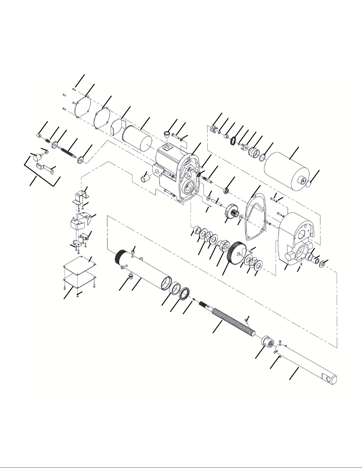
3-1 Exploded View
47
46
58
57
56
55
56
59
49
47
52
50
51
62
47
63
45
Section III
Views & Parts List
44
43
42
67
36
34
28
Linear Actuator 1500 AC Assembly
35
48
66
40
19
41
20
21
2
39
15
20
23
16
29
39
22
14
17
24
9
18
8
11
13
16
20
10
21
30
8
20
31
9
25
38
12
32
7
5
1
6
33
37
3
19
4
26
27
Page 10

10
3-2 Parts List – Linear Actuator 18030090
Table 3-2 Parts list
Item
1 AC Lower Housing (1) 36 Air Vent (2)
2 AC Upper Housing (1) 37 Set Screw (1)
3 Motor (1) 38 Gasket (1)
4 Hole Plug (1) 39 Dowel Pin (2)
5 Screws (3) 40 Screw (5)
6 Lock Washers (3) 41 Lock Washer (5)
7 O Ring (1) 42 Upper Bushing (1)
8 Retaining Ring (2) 43 Capacitor (1)
9 Coupling Half (2) 44 Capacitor Insulation (1)
10 Drive Spring (1) 45 Cover Gasket (1)
11 Rubber Grommet (1) 46 AC Cover (1)
12 AC Insert (1) 47 Screw (10)
13 Miniature Bearing – 8mm (1) 48 Tapered Plug (1)
14 Input Pinion (1) 49 AC Limit Switch Bracket (1)
15 Miniature Bearing – 6mm (1) 50 Limit Switch Insulation (2)
16 Thrust Washer (2) 51 Switch (2)
17 Dowel Pin (1) 52 Pan Head Screw (4)
18 Cluster Gear (1) 53 Red Jumper Wire (1)
19 Casting Bushing (2) 54 Blue Jumper Wire (1)
20 Thrust Washer (4) 55 AC Limit Switch Shaft (1)
21 Thrust Bearing (2) 56 AC Limit Switch Nut, Cam (2)
22 Spacer Nut (1) 57 Potentiometer Worm (1)
23 Set Screw (1) 58 Flanged Bronze Bearing (1)
24 Output Gear (1) 59 AC Nut Retainer (1)
25 Woodruff Key (1) 60 Potentiometer Assembly (1)
26 Gear Spacer (1) 60A
27 Washer (1) 61 Instruction Decal (1)
Translating Tube Assembly. Components 28-35 62 Switch Cover Gasket (1)
28 Guide Bearing (1) * 63 AC Switch Cover (1)
29 Lifting Screw (1) * 64 Warning Decal (1)
30 Dowel Pin (1) * 65 Large Decal (1)
31 Translating Tube Bushing (1) * 66 Compression Spring (1)
32 Retaining Ring (4) * 67 Pipe Plug (4)
33 AC Translating Tube Assy (1) * 68 Small Name Plate (1)
34 Outer Tube (1) * 69 Drive Screw (2)
35 Seal (1) *
* Replacement and spare parts available only an assembly, see Section 2-2 Spare Parts.
Item
Potentiometer Gear (1)
Page 11
11
Section IV
Technical Drawings and Illustrations
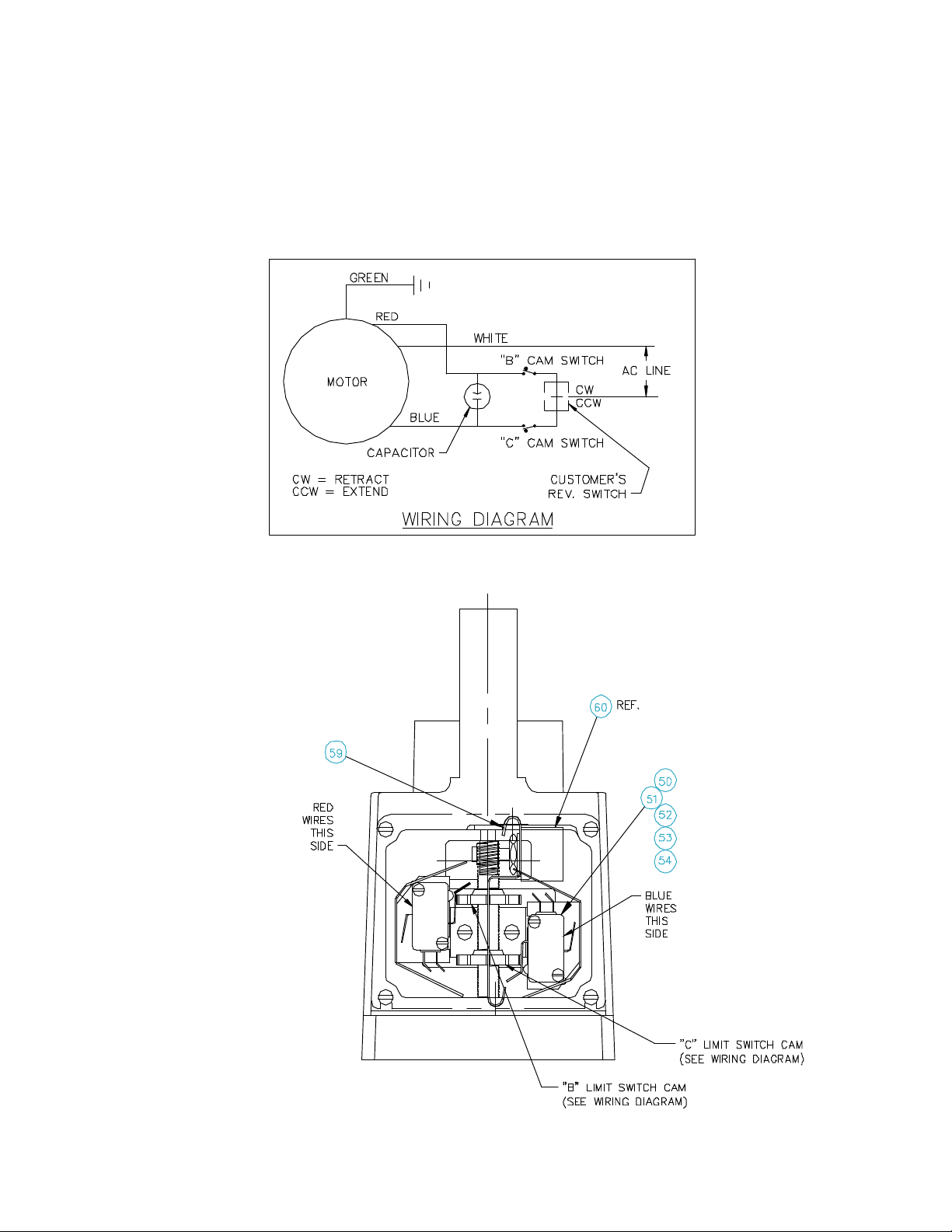
4-1 Wiring Diagram
4-2 Limit Switch
Page 12
12
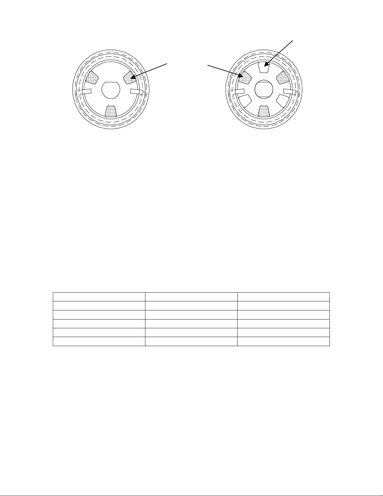
4-3 Brake Assembly Diagram
View A
when the motor is stopped
View B
Motor Coupling
Pinion Coupling
This is a view of the brake assembly
installed from the motor end with one
coupling half. It is the view looking into
the lower housing before the motor
coupling half or rubber grommet is
assembled.
When properly assembled, this
coupling will not rotate in the CW or
the CCW direction. This braking action
allows the actuator to hold position
.
This is a view of the installed brake
assembly from the motor end with
both coupling halves shown.The
unshaded coupling tangs are the
motor half coupling.
When properly assembled, this
coupling half will rotate in both the
CW and CCW direction. This allows
the motor to be reversed
.
4-4 Travel Limit Chart
Models with limit switches (089030090) based on clevis end condition
Effective travel ( rise) Minimum dimension Maximum dimension
3” 17.13” 20.13”
6” 20.13” 26.13”
12” 26.13” 38.13”
18” 32.13” 50.13”
24” 38.13” 62.13”
Minimum dimension and maximum dimensions are measured from clevis eye to clevis
eye. Use these formulae to calculate the dimensions.
Minimum = Rise” + 14.13”
Maximum = (Rise” x 2) + 14.13”
Page 13

13
Section V
Part Numbers and Ordering
5-1 Ordering Information
Capacity Voltage Options Base Mounting Screw end Travel
L
A
05
(500#)
15
(1500 #)
2
(12 VDC)
5
(115 VAC)
2
(12 VDC)
5
(115 VAC)
SC
C
Clutch
L Limit Switch SC CL Clevis
C
Clutch
L Limit Switch CL Clevis
P Limit Switch
w/Potentiometer
C
Clutch
L
Limit Switch
L
Limit Switch
P
Limit Switch
w/Potentiometer
Standard Clevis
RC
Rotated Clevis
Standard Clevis
RC
Rotated Clevis
SC
Standard Clevis
Standard Clevis
TM
Trunnion Mount
Standard Clevis
TM
Trunnion Mount
Standard Clevis
TM
Trunnion Mount
Standard Clevis
TM
Trunnion Mount
CL Clevis
TE Threaded
CL Clevis
TE Threaded
CL Clevis SC
TE Threaded
CL Clevis
TE Threaded
TE Threaded
CL Clevis
CL Clevis SC
TE Threaded
CL Clevis
TE Threaded
CL Clevis SC
TE Threaded
CL Clevis
TE Threaded
CL Clevis SC
TE Threaded
CL Clevis
TE Threaded
CL Clevis SC
TE Threaded
CL Clevis
TE Threaded
03
06
09
12
18
03
06
12
18
24
Linear Actuator Part Number Structure:
Product – Size – Motor Voltage – Options – Mounting – End Condition - Travel
EXAMPLE – LA155PSCCL-12
Product – LA
Size – 1500# (15)
Motor Voltage – 230v AC (5)
Options – Potentiometer and limit switches (P)
Mounting – Standard Clutch (SC)
End Condition – Clevis (CL)
Travel – 12”
Page 14

14
5-2 Maintenance Log
Date Maintenance Performed Initials
Page 15

15
This page was intentionally left blank.
Page 16

16
Joyce/Dayton Corp
P.O. Box 1630
Dayton, Ohio 45401
Phone (800) 523-5204 (U.S. & Canada); (937) 294-6261 Fax (937) 297-7173
www.joycedayton.com E-mail: [email protected]
FB0188A 11/06
 Loading...