

Page 1

Joyce/Dayton Corp
.
Operation and Maintenance Manual
Joyce/Dayton Electric Cylinders with Ball Screw
Standard, Motor mount, and ComDRIVE style
WARNING!
The recommendations in this manual for installation, operation and maintenance must be followed to
ensure safe use. All persons responsible for the installation and use of Joyce/Dayton Electric Cylinders
must be familiar with the contents of this manual.
The customer is responsible for guards and other protective devices and for ensuring that Electric
Cylinder usage conforms with local and national operating and safety codes appropriate to the class of
equipment into which the Electric Cylinder is installed.
©2009 Joyce/Dayton Corp. All rights reserved FB0198 – 9-09
Page 2

Table of Contents
Section I – General Information
1-2 Purpose and Scope .........................................................2
1-3 Receipt of Product...........................................................2
1-4 Warranty............................................................................2
1-5 Precautions for Use.........................................................3
1-6 General Installation Instructions ...................................3
1-1 Contact Joyce Dayton.....................................................2
Section II – Maintenance
2-1 Lubrication........................................................................4
2-2 Repair Parts.......................................................................5
2-3 Disassembly Procedure..................................................5
Section III – Views and parts lists
3-1 Ball Screw Electric Cylinder (ECB) Drawing................6
3-2 Ball Screw Electric Cylinder (ECB) Parts List.............7
3-3 Electric Cylinder Part Numbers.....................................8
3-4 Maintenance Log and Serial Tag ..................................10
Section I
General Information
1-1 Contact Joyce/Dayton Corp
Joyce/Dayton Corp.
P.O. Box 1630
Dayton, OH 45401
(800) 523-5204 (US and Canada only)
(937) 294-6261 (937) 297-7173 Fax
Email: [email protected]
Website: www.joycedayton.com
1-2 Purpose and Scope
This manual provides installation, operation and maintenance instruction for the standard
Joyce/Dayton Electric Cylinders (ECB). Although this manual covers the standard Electric
Cylinders, some may vary significantly from this manual. For special units not covered please
contact Joyce/Dayton Corp. for assistance.
1-3 Receipt of Product
All equipment should be immediately inspected upon receipt for any damage and to verify correct
product and quantities. Any problems should be reported to Joyce/Dayton Corp. and the freight
carrier as soon as possible. Products returned without a Return Goods Authorization (RGA) will
not be accepted.
1-4 Warranty
Seller warrants its products to be free from defects in material and workmanship under normal
and proper use in accordance with instruction of seller for a period of one year from the date of
shipment to buyer. Seller's liability under such warranty or in connection with any other claim
2
Page 3

relating to the products shall be limited to the repair, or at seller’s option, the replacement or
refund of the purchase price, of any products or parts or components thereof which are returned
to seller freight prepaid and which are defective in material or workmanship. Products or parts or
components thereof, which are repaired or replaced by seller, will be returned to buyer freight
collect. This warranty is not intended to cover consumer products, as defined in the MagnusonMoss Warranty-Federal Trade Commission Improvement Act, 15 U. S. C. Sections 2301-12,
which are purchased by buyer for purposes other than resale. If buyer is not intending to resell the
products, and if the products are consumer products as defined in the Magnuson-Moss Act, the
foregoing warranty, but not the limitation of seller's liability, shall be null and void. EXCEPT AS
EXPRESSLY STATED ABOVE, SELLER MAKES NO WARRANTY, EXPRESS OR IMPLIED,
WHETHER OF MERCHANTABILITY OR FITNESS FOR ANY PARTICULAR PURPOSE OR
USE OR OTHERWISE, ON THE PRODUCTS, OR ON ANY PARTS OR LABOR FURNISHED
DURING THE SALE, DELIVERY OR SERVICING OF THE PRODUCTS.
1-5 Precautions of Use and Installation
1. Mechanical stops provided on the Electric Cylinders, (ECB), are not designed to be used as
end-of-travel stops. The customer is responsible for setting travel limits.
2. Travel can be limited using optional limit switches. These limit switches need to be set by the
customer. In most applications, factory or manufacturer-assisted installation is not required.
However, it is necessary that appropriate, qualified personnel perform the installation of
Joyce/Dayton products.
3. Joyce/Dayton Electric Cylinders, (ECB), are not rated for shock-loading or extreme vibration. It
is the responsibility of the user to ensure these conditions are not imposed on the actuator.
4. In the event that service or maintenance is required, the load must be secured or removed
before any work can begin.
5. The Electric Cylinder (ECB) can be mounted and operated in any orientation. Length of
allowable rise may differ for vertical and horizontal applications. Check the catalog and this
manual for allowable rises. Standard Electric Cylinders, (ECB) have vents in the
protection tube (outer tube). Additional holes will be plugged. Properly plug or vent
holes to prevent dirt or moisture form contaminating the actuator.
6. Never allow the Electric Cylinder to retract beyond the minimum closed position or extend
beyond the maximum open position, as damage to the unit can occur.
7. External temperature may exceed 230 Degrees F. near maximum duty cycle. Use caution to
prevent personal injury.
8. Do not use in applications where Electric Cylinder can be jammed against an
immovable object.
9. A brake motor is required on Ball Screw Electric Cylinders to prevent the load from drifting
when power is off.
1-6 General Installation instructions
1. Ensure that all personnel who will service or operate equipment are familiar with its use and
limitations.
2. Secure or remove the load before any installation procedures begin.
3. Be certain the rating of the Electric Cylinder (ECB) meets or exceeds the load.
4. The Electric Cylinder (ECB) must be mounted on a rigid structure sufficient to support the
maximum possible load. An under-designed structure could lead to premature wear or failure.
5. Drive shaft alignment is critical. Misalignment will cause reversing stresses in rotating
members and will lead to fatigue failure. Correct coupling specification is critical for systems
with more than one Electric Cylinder.
6. For systems with more than one Electric Cylinder, confirm that the Electric Cylinders and
shafts operate without binding or excessive force before power is applied.
7. When fastening the load to an Electric Cylinder, make sure the actuator is in the retracted
position. This positions the load accurately with respect to the lifting screw centerline. Never
pull the translating tube to one side to make connection with your structure. Fully extend the
Electric Cylinder to make sure the load is aligned with the translating tube.
3
Page 4

8. All Electric Cylinders are to be mounted with S.A.E. Grade 8 bolts or equivalent.
9. Torque the mounting bolts in a systematic pattern to avoid damage to the actuator.
10. Optional limit switches, which may be furnished with the Electric Cylinder, are NOT pre-set.
They require field adjustment before use.
Section II
Maintenance
2-1 Lubrication
Electric Cylinder
1. Electric Cylinders are lubricated before leaving the factory.
2. Do not operate Electric Cylinder without lubrication.
3. The lifting screw and tube are lubricated with Mobilith Mobilgrease XHP 221 grease, or
equivalent.
4. The housing is lubricated with XHP 461 grease.
5. The products listed are recommended by the lubricant manufacturers to meet the
requirements for normal operation. The listing of brand names is solely for the convenience of
users of Joyce/Dayton equipment and their lubricant suppliers; it does not constitute any
endorsement. Joyce/Dayton assumes no responsibilities for the quality, performance or
availability of any listed products.
Company Brand Name Electric Cylinder
Component
Exxon Mobil Mobilgrease XHP 461 Housing
Exxon Mobil Mobilith SHC PM Housing
Exxon Mobil Mobilith SHC 221 Housing
Exxon Mobil Mobilgrease XHP 221 Lifting screw and Tube
Gear Reducer (option)
1. Standard ComDRIVE Electric Cylinder Gear Reducers are lubricated with AGMA 7
compounded oil (ISO Grade 460) before leaving the factory.
2. The products listed are recommended by the lubricant manufacturers to meet the
requirements for normal operation. The listing of brand names is solely for the convenience of
users of Joyce/Dayton equipment and their lubricant suppliers; it does not constitute any
endorsement. Joyce/Dayton assumes no responsibilities for the quality, performance or
availability of any listed products.
Company Brand Name ComDRIVE Electric
Cylinder component
Mobil Oil Mobil 600W Cylinder Oil Gear reducer
Mobil Oil Mobil 85W100 Gear Reducer
Mobil Oil Mobil SHC 634 (synthetic) Gear Reducer
3. Synthetic Lubricants are recommended for severe service applications. These lubricants are
more stable in regard to viscosity and temperature. They have a longer service life so they
may require fewer oil changes. They also decrease friction and wear on the gear reducer so
they may increase the life of the gear reducer.
4. This synthetic lubrication is also compatible with nitrile seal material as well as with alloy
bronze gear material.
4
Page 5

2-2 Repair Parts
Repair parts may be obtained by calling Joyce/Dayton Customer Service at (800) 523-5204, (937)
294-6261, (937) 297-7173 (facsimile) or your local sales representative. When ordering repair
parts, please supply the serial number (located on the nameplate).
The following parts are recommended for rebuild or spares. See Sections 3-1 and 3-2 and Parts
List in Section 3-3.
A. (2) Thrust Bearing
B. (1) Worm Gear Nut
C. (1) Worm
D. (2) Worm Shaft Bearing
E. (2) Worm Shaft Seal
F. (1) Translating Tube and Screw Assembly
G. (2) Bushings
H. (1) Wiper Seal
I. (1) Motor (Direct Drive or ComDRIVE option)
J. (1) Gear reducer (ComDRIVE option)
K. (1) Motor mount (Direct Drive option)
2-3 Disassembly of Electric Cylinder
Before beginning to disassemble these units make sure the load has been removed and secured
according to best practice standards for safety..
Direct Drive option and ComDRIVE option
1. Motors supplied with Direct Drive and ComDRIVE units are not user serviceable.
2. Loosen the bolts attaching the motor to the jack or to the gear reducer and remove the motor.
3. The gear reducer on ComDRIVE units must also be removed before the electric cylinder can
be disassembled.
Limit Switch, Encoder, or Potentiometer option
4. Loosen the bolts holding the limit switch, encoder, or potentiometer and remove from their
mounting bracket.
5. Loosen the bolts attaching the mounting bracket to the electric cylinder and remove
Disassembly of ECB
6. Loosen the hex head screws on the worm bearing caps or remove the mounting adapters
described above.
7. Remove the worm bearings and remove the worm shaft through the end of the sleeve. This
may also be removed after the Translating Tube and Screw Assembly is removed later in the
process.
8. Extend the translating tube assembly a few inches. This positions the components to be more
easily disassembled.
9. Loosen the setscrews at the base of the protection tube.
10. Unthread the protection tube and pull it off over the end of the translating tube assembly.
11. Loosen the set screws that secure the sleeve cap. Unthread the sleeve cap and remove it.
12. This will allow the translating tube assembly along with several internal components to be
pulled up out of the sleeve.
13. Remove the retaining ring located at the base of this assembly and remove the key.
14. Remove any portion of the lower bearing that may be attached to the worm gear nut.
15. Unthread the worm gear nut from the lifting screw.
16. The upper thrust bearing can now be separated from the worm gear nut along with the seal.
17. Remove the grease from the cavity and inspect parts for damage or wear.
18. Assemble replacement components by carefully reversing the disassembly process.
5
Page 6
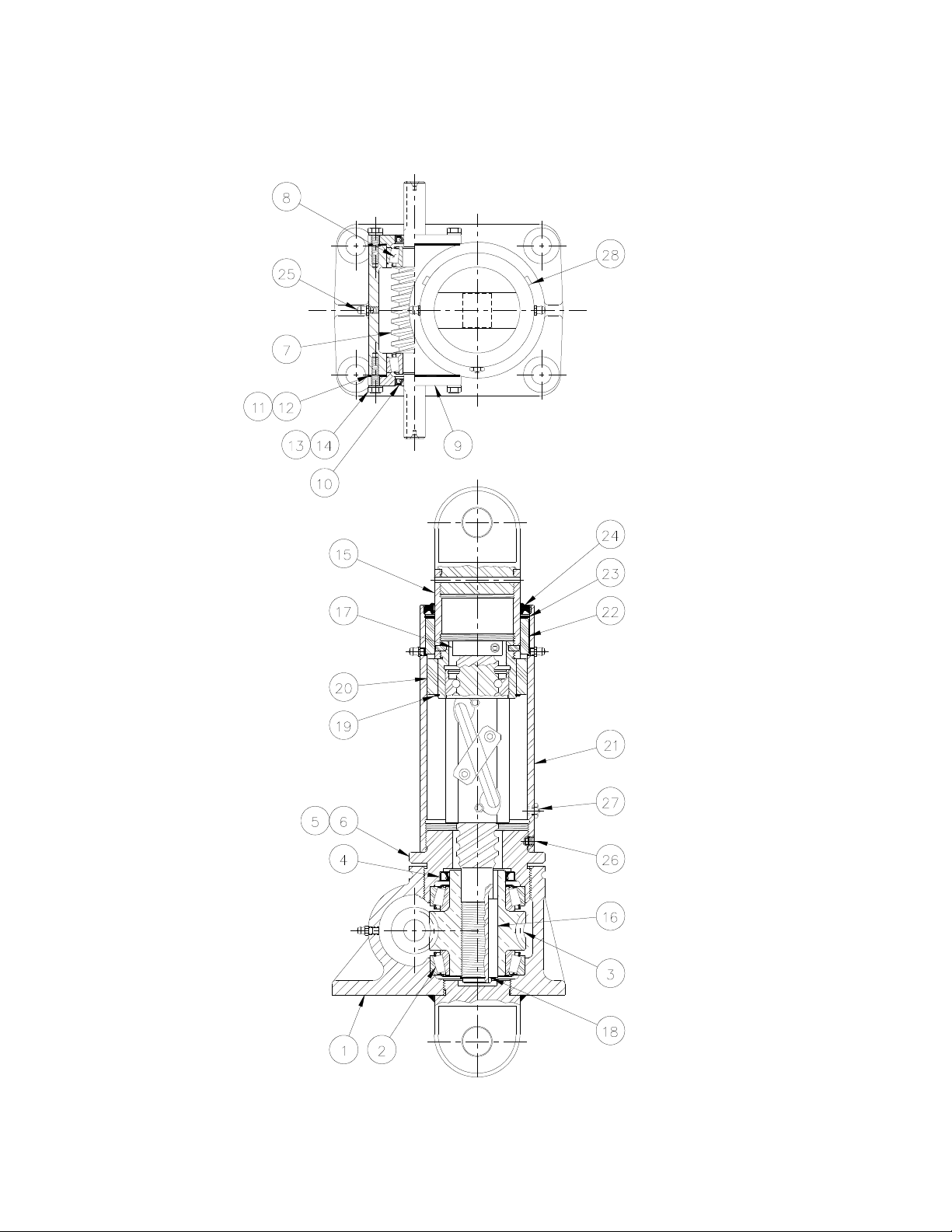
3-1 Ball Screw Electric Cylinder
Section III
Drawings
6
Page 7

Table 3-2 Parts list – Ball Screw Electric Cylinder
Item
1 Electric Cylinder Sleeve (1)
2 Thrust Bearing (2)
3 Worm Gear Nut (1)
4 Seal (1) Lock Washer (4)
5 Sleeve Cap (1) Hex Head Screw (4)
6 Set Screw (4) Pipe Plug (2)
7 Worm (1)
8 Worm Shaft Bearing (2) Key (1)
9 Bearing Cap (1) Retaining Ring (1)
10 Worm Shaft Seal (2) Key (1)
11 Shim, Blue (4) Motor (1)
12 Shim, Clear (2)
13 Hex Head Screw (6)
14 Lock Washer (6)
15 Translating Tube and Screw Assembly (1) Gear Reducer (1)
16 Key (1) Key (1)
17 Stop (1) Hex Head Screw (4)
18 Retaining Ring (1)
19 Retaining Ring (1)
20 Bushing, Translating Tube (1) Woodruff Key (1)
21 Protection Tube (1) Hex Head Screw (6)
22 Bushing, Protection Tube (1) Lock Washer (4)
23 Retaining Ring (1)
24 Double Lip Wiper (1) Shim, Yellow (2)
25 Grease fitting (1) Shim, Clear (6)
26 Set Screw (2) Shim, Blue (6)
27 Air Vent (1) Worm Shaft Seal (1)
28 Pipe Plug (4) Worm Shaft Bearing (1)
Sleeve With Rotated Clevis (1)
Plug (1)
Flanged Sleeve (1)
Clevis Pin (1) Screw (4)
Dowel Pin (1)
Set Screw (2)
Other Options (not shown)
Female Rod Clevis (1)
Male Clevis Rod End (1)
Item
Roll Pin (1)
Optional Limit Switch Adapter (1)
Optional Limit switch (1)
Flat Washer (4)
Screw (1)
With Motor Mount (not shown)
Motor Mount Bracket (1)
Hex Head Screw (4)
Coupling (1)
With ComDRIVE (not shown)
Reducer Mounting Adapter (1)
Lock Washer (12)
Motor (1)
Hex Head Screw (4)
Limit switch Components (not shown)
7
Page 8

3-3 Ball Screw Electric Cylinder Part Numbers
6:1
12:1
6:1
6:1
6:1
12:1
6:1
12:1
Operating Torque
(inch lbs.) @ Worm
.013W*
.005W*
.026W*
.051W*
.011W*
.006W*
W*
.032W*
.018W*
.011W*
Model Number
Static
Capacity
ECBL62.5
ECBL122.5
ECBL242.5
2.5 TON
ECBM62.5 ECBH62.5
2.5 TON
2.5 TON
ECBL63
ECBL123
ECBL243
3 TON
ECBH63
ECBH123
ECBH243
3 TON
Lifting Screw
Diameter (inches)
Thread
Pitch/ Lead
(inches)
Worm Gear
Ratio
Worm Shaft Turns
for 1" Travel
Tare Torque
(inch/Lbs.)
Starting
Torque
(Inch/lbs.)
RPM
Translating Tube
Torque * (inch lbs.)
Base Weight
( lbs)
1
.25
24:1
1
.5
1
1.0
1.15
.2
24:1
1.06
.625
24:1
24
48
96
8
7
6
.017W*
.011W *
.008W*
.008W*
@ 500 RPM
12
8
.033W*
@ 500 RPM
6
8
.065W*
@ 500 RPM
30
60
120
9
8
7
.013W*
.008W*
.006W*
.004
@ 500 RPM
9.6
19.2
38.4
9
8
7
.041W*
.025W*
.018W*
@ 500 RPM
.045 W* .089 W* .177W .036 W* 111 W*
30 30 30 32 32*
Add to Basic Jack
Weight (lbs.) for
each Additional 1"
of Travel
Max. Vertical Rise
Max. Horizontal
Rise
W*= Load in pounds
Tare Torque: The initial torque needed to overcome seal and normal assembly drag. This value must be added to starting torque
or operating torque values.
Starting Torque: Torque value required to start moving a given load (dissipates to operating torque value once the load begins
moving).
Operating Torque: Torque required to continuously raise a given load at the input RPM listed.
Translating Tube Torque: Torque required to resist the tube rotation.
1.5 1.5 1.5 1.9 1.8
41” 44” 41” 56” 46”
31” 33” 31” 42” 34”
8
Page 9

3-3 Ball Screw Electric Cylinder Parts Numbers (continued)
Worm Gear
6:1
12:1
6:1
12:1
6:1
12:1
Torque †
(inch lbs.) @
.025W*
.014W*
.009W*
.052W*
.018W8
.098W*
.034W*
.019W*
.017W*
.031W*
.020W*
096W*
Tube Torque
Add to Basic
Additional 1"
Max. Vertical
Model
Number
Static
Capacity
Lifting
Screw
Diameter
(inches)
Thread
Pitch/ Lead
(inches)
Ratio
Worm Shaft
Turns for 1"
Travel
Tare Torque
(inch/Lbs.)
Starting
Torque
(Inch/lbs.)
Operating
Worm RPM
Translating
* (inch lbs.)
Base Weight
( lbs)
ECBL65
ECBL125
ECBL245
5 TON
1.5
.474
24:2
12.66
25.33
50.66
15
13
12
.032W*
.020W*
.015W*
@ 300 RPM
.084W .177W* .332W* .084W* .172W* .332W .089W*
65 65 65 81 81 81 164
ECBM65
ECBM125
ECBM245
5 TON
1.5
1.00
24:2
6
12
24
15
13
12
.067W*
.042W*
.031W*
.030W*
@ 300 RPM
ECBH65
ECBH125
ECBH245
5TON
1.5
1.875
24:2
3.2
6.4
12.8
15
13
12
.125W*
.079W*
.057W*
.055W*
@ 300 RPM
ECBL810
ECBL2410
10 TON
1.5
.474
8:1
24:1
16.88
50.66
30
25
.023W*
.012W *
.008W*
@ 200 RPM
ECBM810
ECBM2410
10 TON 10 TON
1.5
1
8:1
24:1
8
24
30
25
.049W*
.024W*
.040W*
@ 200 RPM
EBH810
ECBH2410
2.25
1.875
8:1
24:1
4.27
12.8
30
25
.091W*
.045W*
.074W*
@ 200 RPM
ECBL820
ECBL2420
20 TON
2.25
.5
8:1
24:1
16
48
60
40
.026W*
.014W*
.
@ 200 RPM
Jack Weight
(lbs.) for
each
of Travel
Rise
Max.
Horizontal
Rise
W*= Load in pounds
Tare Torque: The initial torque needed to overcome seal and normal assembly drag. This value must be added to starting torque
or operating torque values.
Starting Torque: Torque value required to start moving a given load (dissipates to operating torque value once the load begins
moving).
Operating Torque: Torque required to continuously raise a given load at the input RPM listed.
Translating Tube Torque: Torque required to resist the tube rotation.
2.3 2.3 2.3 2.3 2.3 2.3 4.5
54” 40” 59” 38” 38” 41”
72”
40” 38” 44” 28” 28” 31” 54”
9
Page 10
3-4 Maintenance Log and Serial Number Tag
Date Maintenance Performed Initials
Joyce Dayton Serial Number Tag
To obtain product information needed for maintenance, repair and reorder,
contact Joyce Dayton Corporation and provide the serial number.
Joyce/Dayton Corp
P.O. Box 1630
Dayton, Ohio 45401
Phone (800) 523-5204 (U.S. & Canada); (937) 294-6261 Fax (937) 297-7173
www.joycedayton.com E-mail: [email protected]
©2009 Joyce/Dayton Corp. All rights reserved FB0198-9/09
10
 Loading...