


_______________________
Operating manual
UPS - System
POWERMASTER
POWERMASTER M
POWERMASTERPOWERMASTER
1000VA – 7Min.
M MIL
MM
BAX 3330 E
UPS-Division Issued 15. August 2006
Groninger Straße 29-37
D-26789 Leer/Ostfriesland
P.O. Box 1580 / D-26765 Leer
Tel.: ++ 491 6002 - 0
Fax.: ++ 491 6002 - 10
E-Mail: GL@JOVYATLAS.DE
Internet: WWW.JOVYATLAS.DE
JOVYATLAS
JOVYATLAS
Elektrische Umformtechnik GmbH

Relevant information!
Please read this manual thoroughly before
installation.
Pay attention to each relevant information
especially the specific comments on the
separate chapters. Careful reading will avoid
malfunctions of the device later on.
If there is any problem please contact our
service - division.

JOVYATLAS UPS-division
List of contents
Chapter Contents Page
1. General information 4
2. Description of the system 5
3. Description of the functions 5
4. Technical data 6
5.1 Front view POWERMASTER M – series 115V 7
5.2 Back view POWERMASTER M – series 115V 7
6. Electrical connection 8
6.1 Electrical Connection of the UPS-system 8
6.2 Commissioning of the UPS-system 8
6.3 Shut-down of the UPS-system 9
7. Operating and display elements for 115V - Series 10
7.1 Display of the loading of the UPS-system for 115V - Series 11
7.2 Display of the charge state of the batteries for 115V - Series 11
7.3 Handling of the panel for 115V - Series 12
8. Alarm messages for 115V - Series 13
8.1 Displayed alarm messages for 115V - Series 13
8.2 Reset of the alarm messages for 115V – Series 14
8.3 Acoustical alarms and troubleshooting for 115V - Series 14
9. Remote control for 115V - Series 15
10. Maintenance 15
Operating manual POWERMASTER M MIL BAX 3330E page 3

JOVYATLAS UPS-division
1. General information
To prevent self discharging of the batteries you have to connect the UPS to
The batteries built-in in this system are designed for the necessary bridging time
at nominal load of the UPS. A no-load running operation of the UPS with a long
time in battery operation could led to battery damages. This effect is determined
by the technique of the battery, as the cut-off voltage will not be reached at a
long discharging time.
mains and put it into operation within four weeks after receipt!
Relevant information!
Attention!
Only qualified personal is allowed to open the UPS.
The connection of the UPS has to be done according to VDE considering the local rules.
Don't cover the ventilation slots at backside of the UPS. Keep a distance to the surrounding walls of at least 100
mm.
The UPS is built up according to protection class IP21 and has to be installed in dry and clean rooms with a
surrounding temperature of 20 °C. A lower operation temperature would decrease the autonomy time.
Don't connect devices with connection-cables exceeding the length of 10 meters. This measure serves for the
observance of the EMV-norm.
It's not allowed to carry out structural changes on the UPS. Improper operation causes the extinction of warranty.
To prevent overload or a frequent switch-over to bypass mains caused by non-sinusoidal current peeks
of the connected loads you shouldn't connect laser printer, faxes or similar devices to the UPS.
If it's necessary to connect such devices to the UPS, you have to choose an UPS with a higher nominal
power than the maximum of the current spikes.
The power semiconductors of the UPS could be immediately destroyed by the connection of loads with a
The battery isn’t galvanic isolated from the mains, so it’s possible that there is mains-potential at the
Attention:
half-sinusoidal rectifier.
battery-terminals!
Operating manual POWERMASTER M MIL BAX 3330E page 4
JOVYATLAS UPS-division
2. Description of the system
This power supply system out of the POWERMASTER M series is an especially build ups for ship use. The
ups is qualified for power supply of important consumers in ship use, such as personal computer, computercontrolled devices and similar units. The output voltage is sinusoidal. In normal operation the connected load is
fed in online operation by the mains through the internal rectifier and inverter. Mains disturbances such as
voltage-variations, distortions, noise etc. are filtered. The internal battery is permanently charged in a careful
way by the charging rectifier in trickle charge mode
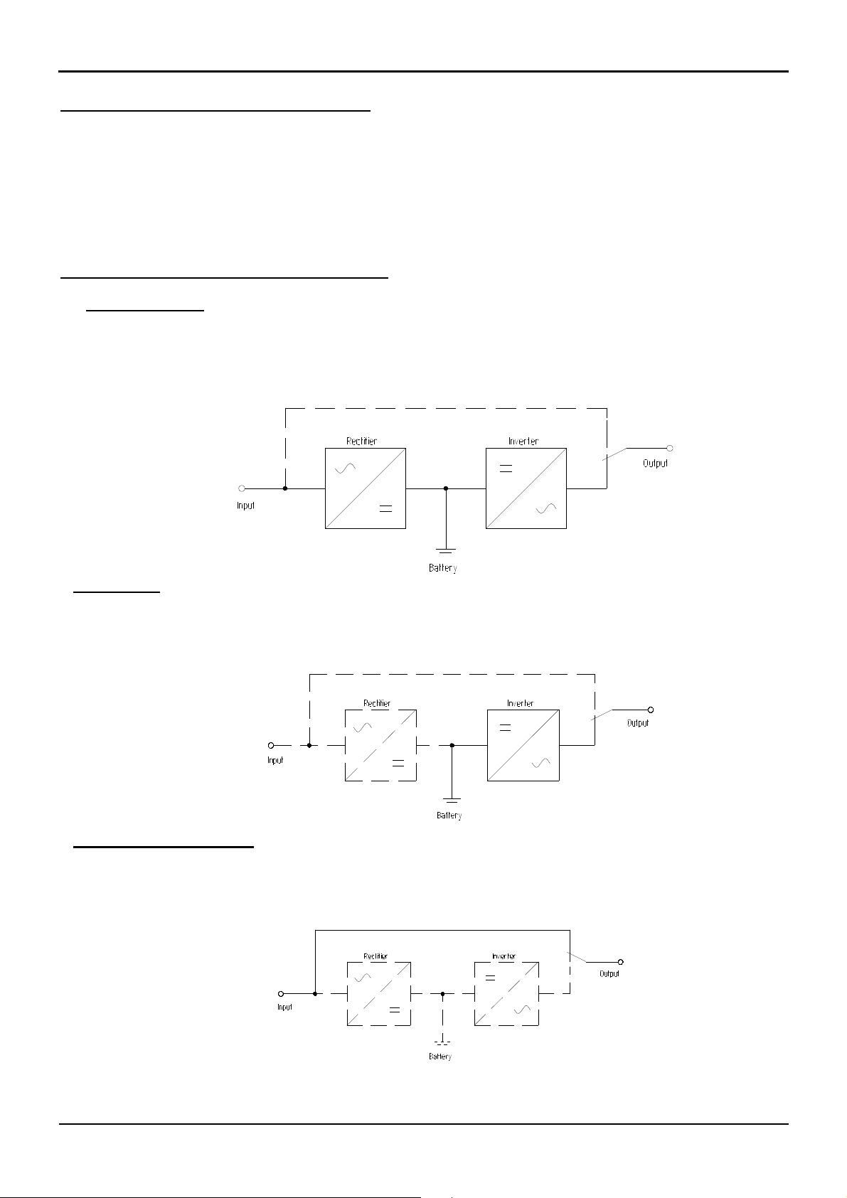
3. Description of the functions
Normal operation
In normal operation the battery and the inverter are fed by the rectifier (online-operation).
The conversion of the AC-voltage into DC-voltage and back into AC-voltage ensures a sinusoidal output
voltage with a low distortion. The DC-voltage is also necessary for the battery-charging. The inverter feeds the
connected loads.
Mains failure
In case of mains failure the inverter is fed by the battery.
At the output the output voltage of the inverter is still available.
Inverter failure or overload
In case of inverter failure or overload the load is switched back to the mains.
In case of mains failure the consumers are not supplied in that case any longer.
Operating manual POWERMASTER M MIL BAX 3330E page 5

JOVYATLAS UPS-division
Width
4. Technical data
POWERMASTER S 1000-7-115
Input Voltage 115V (80V ... 138V)
Input power factor
Frequency 50Hz / 60Hz ±5%
Current at 115V 12,4A
Required fuse C20A
Battery voltage 36V
Output power 1000VA
Affective power 700W
Efficency INV 85%
Output voltage 115V (sinuswave)
Output power factor
Frequency 50Hz / 60Hz ±0.5%
Distorsion < 3% (at linear Load)
Overload capability >105% for 10s /> 130% for 300ms
Crest Factor 3 : 1
Operation mode Online
Signalisation Data processing interface
Radio interferance
degree
According to the rules
of
Loudness < 45 dBA
Temperature 0°C ... 55°C
If temperature is exceeding 55°C the ups will switch to bypass, the load is now not
Humidity Max. 95% non condensing
Dimension (mm)
Height
Depth
Weight (kg)
(incl. Battery)
Acc. EN 50091-2 : 1994 Klasse B
cos φ: 0,98
C-Automatic
cos φ: 0,7
CE, EN, IEC, VDE
buffered by battery
483 (19-Inch)
131
404
22
Operating manual POWERMASTER M MIL BAX 3330E page 6
JOVYATLAS UPS-division
483
131
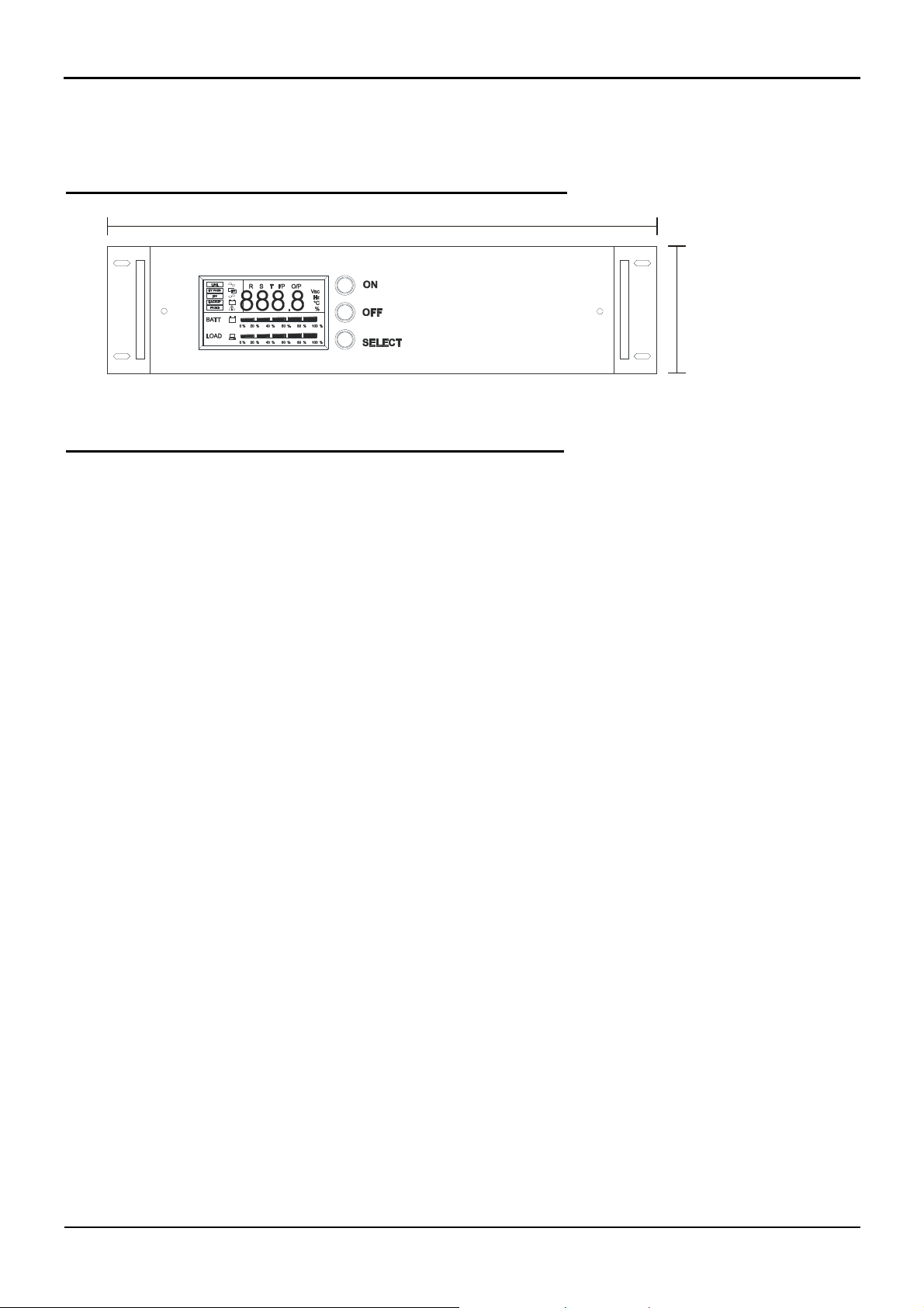
5.1 Front view POWERMASTER M – series 115V
technical modifications are possible
5.2 Back view POWERMASTER M – series 115V
Attention in this case the main input plug and the load output plug are modified in that
way that there are special input socket and output socket are used on the rear side of the ups.
Operating manual POWERMASTER M MIL BAX 3330E page 7
JOVYATLAS UPS-division
6. Electrical connection
Only qualified personnel is allowed to work on the UPS-system.
The respective safety regulations have to be considered.
The labeling of the conductors has to be made according DIN40705,2.80 and DINEN60445,09.91!
Ensure a sufficient dimensioning of the protective conductor connection!
During works on the battery dangerous situations may arise caused by the high
dc-voltage and the high short circuit currents. Therefore works on the system
may be carried out only by using suited protective measures, such as insulated
tools, face- and hands protection and so on.
Attention!
Attention!
6.1 Electrical Connection of the UPS-system
At the UPS-system POWERMASTER M 1000 all connections are located on the rear side of the ups and
are fixed.
6.2 Commissioning of the UPS-system
The mains input has to be connected to plug U9:B1 at the rear of the UPS and the load has to be connected
to plug U9:B3.The communication cable has to be connected to plug U9:B2. The ups starts only by
connecting the ups to the mains and switching on the ON button at the front of the ups, for 2 seconds
continuously.
In case of a lightening bar graph at the battery display you have to press down the mains switch ON for 2
seconds.
ONLY FOR 115V – SERIES:
After a short initialization of approx. 5 sec. the following LED's are lightening:
• LINE (input mains)
• BYPASS (direct bypass onto the input mains)
• LOAD (load of the UPS in %)
• BATTERY (battery state in %)
After approx. 5 seconds further on the announcement
• INV (inverter) appears.
The signal BYPASS goes out. The consumer plug backsides the UPS is fed by the inverter now.
For controlling its correct functioning, disconnect the UPS from the mains, but don’t switch it off.
Now the message LINE extinguishes and the messages INV and BACKUP are lightening.
Operating manual POWERMASTER M MIL BAX 3330E page 8

JOVYATLAS UPS-division
The consumer plug is fed by the inverter which is supplied by the battery. As soon as you `ll connect the UPS
to the mains again, the messages LINE and INV will lighten up again and the BACKUP-announcement goes
out.
After controlling the correct operation of all functions the UPS is ready for
servicing the connected consumers!
Now you can connect the consumers which have to be powered onto the consumer plug at the rear of the
UPS. After that switch-on the UPS and wait until the inverter (INV) has switched-on again. After that you
have to switch-on the consumers.
During the connection of devices with fans or transformers, it is possible that the UPS switches over onto
bypass-operation BYPASS because of the high initial currents of the connected loads. That’s a normal
occurrng, the UPS gets back to inverter operation INV after a few seconds.
If you recognize deviations please contact us ( see also page 2).
Attention!
6.3 Shut-down of the UPS-system
To switch – off the UPS, please press the off – button in front of the ups, the ups will be initialized again and
the message 8888 is shown in the display, the load is still supplied by the ups.
To switch-off the complete UPS, please switch off the mains.
For the system POWERMASTER M 1000 you have to switch-off the mains voltage. After that you have to
press down the mains switch of the UPS OFF.
Operating manual POWERMASTER M MIL BAX 3330E page 9

JOVYATLAS UPS-division
0 % 20 % 40 % 60 % 80 % 100 %
0 % 20 % 40 % 60 % 80 % 100 %
8
OFF
SELECT
16
15
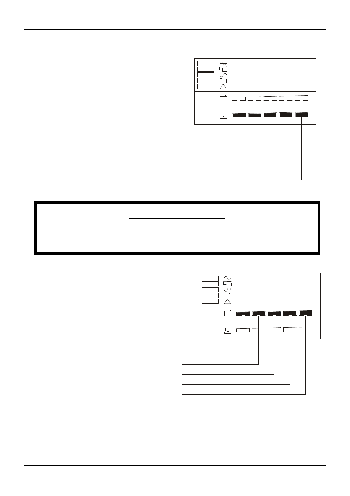
7. Operating and display elements for 115V - Series
8 9 10 11 13
12
14
1
2
3
4
5
6
LINE
BY PASS
INV
BACKUP
FAULT
BATT
INV
!
+
R S T I/P O/P
888
.
Vac
Hz
°C
%
ON
7
LOAD
position display Function of the display
1
2
3
4
LINE
BYPASS
INV
BACKUP
Input mains is connected
Overloaded UPS
Inverter operation (normal operation)
Autonomy operation
5
6
7
8
9
10
11
12
13
14
15
16
Technical deviations may occurr
FAULT
BATT
LOAD
888.8
I/P
O/P
Vac
Hz
°C
ON
OFF
SELECT
UPS failure + fault signal shown at the display
state of battery charge
Loading of the UPS-system
Digital display of the data
Display in connection with the input data
Display in connection with the output data
Display in connection with the input/ output voltage
Display in connection with the input/ output frequency
Temperature of the UPS – system
Switch-on of the UPS-system
Switch-off the UPS-system
Selector switch of the functions
Operating manual POWERMASTER M MIL BAX 3330E page 10
JOVYATLAS UPS-division
Vac
R S T I/P O/P
8
888
Vac
R S T I/P O/P
8
888
7.1 Display of the loading of the UPS-system for 115V - Series
The display of the UPS shows the actual state
of the loading. The loading is shown through five
segments.
1. loading of the UPS amounts to 0% - 20%
2. loading of the UPS amounts to 21% - 40%
3. loading of the UPS amounts to 41% - 60%
4. loading of the UPS amounts to 61% - 80%
5. loading of the UPS amounts to 81% - 100%
The interval cheeping sound and blinking of the loading display are the
indication for overloading of the UPS. The UPS switches – off automatically onto
Relevant information!
bypass operation!
LINE
BY PASS
INV
BACKUP
FAULT
BATT
LOAD
INV
!
+
0 % 20 % 40 % 60 % 80 % 100 %
0 % 20 % 40 % 60 % 80 % 100 %
.
Hz
°C
%
7.2 Display of the charge state of the batteries for 115V - Series
At the display of the UPS the actual charge state of the
system is shown through a segment display
1. loading of the battery amounts to 0% - 20%
2. loading of the battery amounts to 21% - 40%
3. loading of the battery amounts to 41% - 60%
4. loading of the battery amounts to 61% - 80%
5. loading of the battery amounts to 81% - 100%
LINE
BY PASS
INV
BACKUP
FAULT
BATT
LOAD
INV
!
+
0 % 20 % 40 % 60 % 80 % 100 %
0 % 20 % 40 % 60 % 80 % 100 %
.
Hz
°C
%
Operating manual POWERMASTER M MIL BAX 3330E page 11

JOVYATLAS UPS-division
Vac
3
26
Vac
0 % 20 % 40 % 60 % 80 % 100 %
0 % 20 % 40 % 60 % 80 % 100 %
0
115
Vac
6
107
Vac
7
50
Vac
0
50
7.3 Handling of the panel for 115V - Series
By pressing the SELECT push button the actual Input and output parameters were displayed. For a display
of the different parameters one after another you have to press down the push button SELECT durably.
You’ve to release the push button SELECT when the display shows the parameter you’ve asked for. The
following input and output parameters can be displayed.
1. Output voltage
115V
2. input voltage
normally: 1 x 115V
tolerance: 80V - 138V
critical range: <138V
3. input frequency
normally: 50Hz or 60Hz ±3Hz
critical range: <37,5Hz / >82,5Hz
4. output frequency
normal: 50Hz or 60Hz ±3Hz
5. Temperature
The temperature is dependent on the loading
and on the surrounding temperature
of the UPS-system.
Critical range: > 55°C
In this case the ups will switch to bypass
the load isn´t buffered by the ups until the
temperatue will be less then 55°C.
LINE
BY PASS
INV
BACKUP
FAULT
BATT
LOAD
LINE
BY PASS
INV
BACKUP
FAULT
BATT
LOAD
LINE
BY PASS
INV
BACKUP
FAULT
BATT
LOAD
LINE
BY PASS
INV
BACKUP
FAULT
BATT
LOAD
LINE
BY PASS
INV
BACKUP
FAULT
BATT
LOAD
R S T I/P O/P
INV
!
+
R S T I/P O/P
INV
!
+
0 % 20 % 40 % 60 % 80 % 100 %
0 % 20 % 40 % 60 % 80 % 100 %
R S T I/P O/P
INV
!
+
0 % 20 % 40 % 60 % 80 % 100 %
0 % 20 % 40 % 60 % 80 % 100 %
R S T I/P O/P
INV
!
+
0 % 20 % 40 % 60 % 80 % 100 %
0 % 20 % 40 % 60 % 80 % 100 %
R S T I/P O/P
INV
!
+
0 % 20 % 40 % 60 % 80 % 100 %
0 % 20 % 40 % 60 % 80 % 100 %
.
.
.
.
.
Hz
°C
%
Hz
°C
%
Hz
°C
%
Hz
°C
%
Hz
°C
%
Operating manual POWERMASTER M MIL BAX 3330E page 12

JOVYATLAS UPS-division
Vac
E01
Vac
E02
Vac
E03
Vac
E04
Vac
E05
Vac
E07
Vac
E06
8. Alarm messages for 115V - Series
8.1 Displayed alarm messages for 115V - Series
The display of the UPS is designed to send out 7 messages.
These alarm messages can’t be reset without a complete switch-off of the
UPS-system. Please contact our service department in case of alarms like
these.
Attention!
E01 : Inverter failure
The alarm Message E01 will be shown at the display and the
connected load is supplied through the internal bypass further on.
E02 : Overtemperature
The alarm E02 will be shown at the display and the connected
load is supplied through the internal bypass further on.
LINE
BY PASS
INV
BACKUP
FAULT
BATT
LOAD
LINE
BY PASS
INV
BACKUP
FAULT
BATT
LOAD
R S T I/P O/P
INV
!
+
0 % 20 % 40 % 60 % 80 % 100 %
0 % 20 % 40 % 60 % 80 % 100 %
R S T I/P O/P
INV
!
+
0 % 20 % 40 % 60 % 80 % 100 %
0 % 20 % 40 % 60 % 80 % 100 %
Hz
°C
%
Hz
°C
%
E03 : Short circuit on the part of the output
In case of this fault the UPS-system switches off immediately .
„The existing load won’t be supplied any longer“.
The alarm message E03 will be shown at the display
LINE
BY PASS
INV
BACKUP
FAULT
BATT
LOAD
R S T I/P O/P
INV
!
+
0 % 20 % 40 % 60 % 80 % 100 %
0 % 20 % 40 % 60 % 80 % 100 %
Hz
°C
%
E04 : Overloading of the UPS-system
The alarm E04 will be shown at the display and the connected
load is supplied through the internal bypass further on.
LINE
BY PASS
INV
BACKUP
FAULT
BATT
LOAD
R S T I/P O/P
INV
!
+
0 % 20 % 40 % 60 % 80 % 100 %
0 % 20 % 40 % 60 % 80 % 100 %
Hz
°C
%
E05 : Misvoltage (>400VDC) on the part of the d.c.voltage
The alarm E05 will be shown at the display and the connected
load is supplied through the internal bypass further on.
E06 : Misvoltage of the battery
(voltage higher than 280VDC)
The alarm E06 will be shown at the display and the connected
load is supplied through the internal bypass further on.
E07 : Battery voltage is too high or too low
The alarm E07 will be shown at the display and the connected
load is supplied through the internal bypass further on
LINE
BY PASS
INV
BACKUP
FAULT
BATT
LOAD
LINE
BY PASS
INV
BACKUP
FAULT
BATT
LOAD
LINE
BY PASS
INV
BACKUP
FAULT
BATT
LOAD
R S T I/P O/P
INV
!
+
0 % 20 % 40 % 60 % 80 % 100 %
0 % 20 % 40 % 60 % 80 % 100 %
R S T I/P O/P
INV
!
+
0 % 20 % 40 % 60 % 80 % 100 %
0 % 20 % 40 % 60 % 80 % 100 %
R S T I/P O/P
INV
!
+
0 % 20 % 40 % 60 % 80 % 100 %
0 % 20 % 40 % 60 % 80 % 100 %
Hz
°C
%
Hz
°C
%
Hz
°C
%
Operating manual POWERMASTER M MIL BAX 3330E page 13

JOVYATLAS UPS-division
8.2 Reset of the alarm messages for 115V – Series
The alarm messages can’t be reset without switching off the UPS-system completely.
- Switch off the complete load at the consumer distribution pole of the UPS.
High relevant devices and so on won’t be supplied further on. If it’s still
necessary to supply them by the UPS, there has to be installed an external
bypass to feed the loads during a failure or servicing of the UPS further on.
Attention
- Switch off the UPS-systems POWERMASTER M 1000 through removing the input mains of the
device. Than you have to press down the push button OFF in front of the display for 2 seconds. After a
delay of 5 seconds the UPS-system will switch-off completely.
- In case of no success please contact our service-department.
8.3 Acoustical alarms (deactivated) and troubleshooting for 115V - Series
The symbol LINE at the display is out and the symbols INV and BACKUP are lightening.
- Failure of the mains (input mains of the UPS-system)
Measure: Check the line from the terminals to the UPS-system and control the mains fuses of
- The symbol INV is out, the symbol BYPASS is on and the load indication is flashing:
The UPS is overloaded.
the domestic installation
Measure: Decrease the loading of the UPS-system by switching-off separate consumers.
To protect the batteries the UPS-system switches-off at the moment the adjusted
battery cut-off voltage is reached.
Thereby the system is completely released. In case of mains returning the UPSsystem returns automatically into the normal operation state.
Attention!
Operating manual POWERMASTER M MIL BAX 3330E page 14
JOVYATLAS UPS-division
9. Remote control for 115V - Series
The UPS possesses a signal output at the rear side of the ups.
The serial interface serves to the data transfer between a PC and the UPS.
Even the inspection of the UPS can be done by PC. In case of mains failure the switch-off of the UPS is
possible.
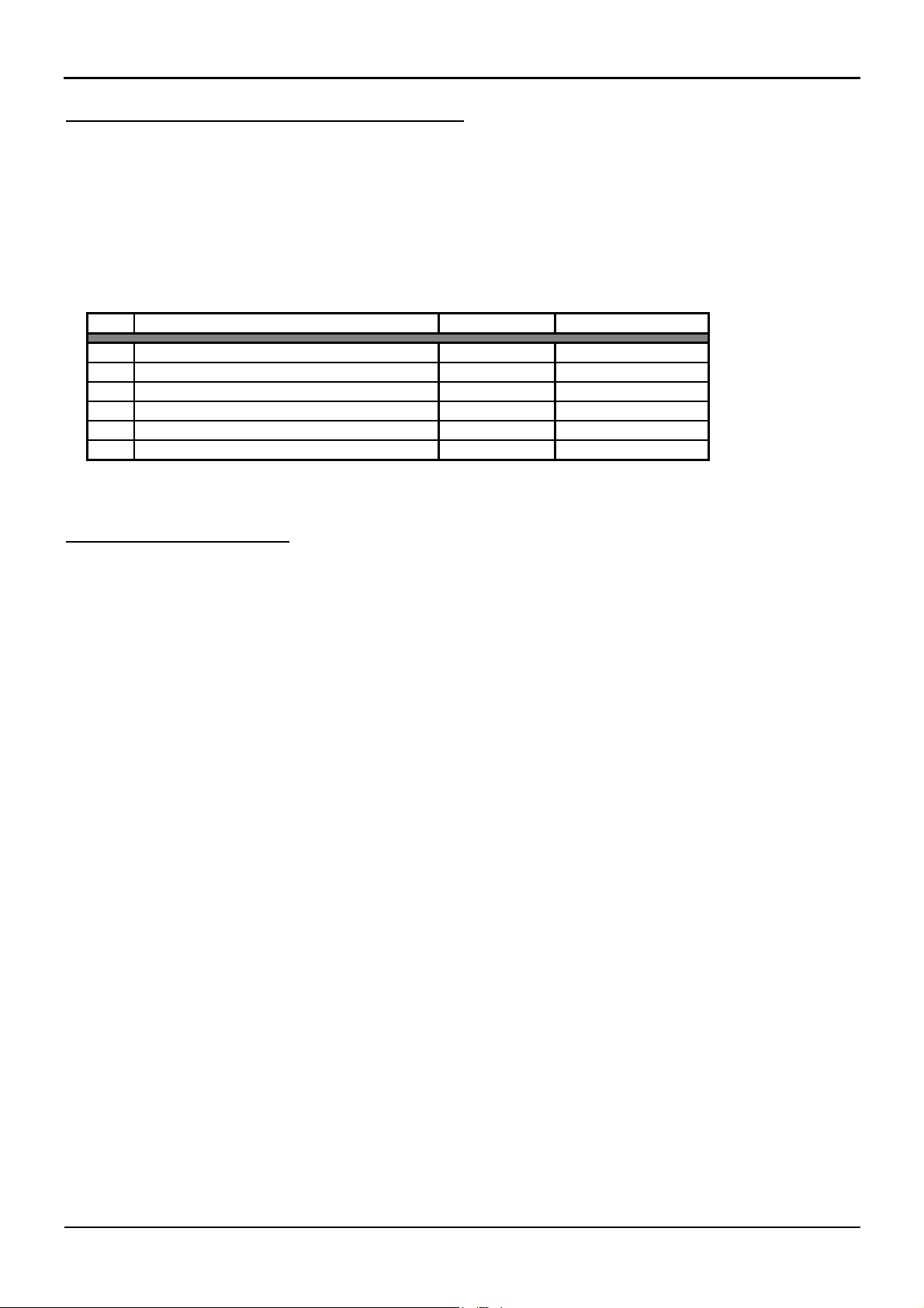
Pin holding of the data transfer interface
PIN Description of the function input / output Contact rating
A Reference earth for PIN B + C output TTL – Logic
B RS 232 data output TX output TTL – Logic
C Remote shutdown RX output TTL – Logic
D Battery low, Battery discharged input TTL – Logic
E Mains failure input TTL – Logic
F Reference earth for PIN D + E (RTN) input TTL - Logic
Technical deviations are possible
10. Maintenance
In case of longer standstill of the UPS (>= 4 weeks) the battery has to be charged monthly. For this charging
you only have to connect the UPS to the mains for a charging time of at least 8 hours.
However we recommend a charging time for about 24 hours.
The battery in its standard version is maintenance-free. Please note the hints of the battery-manufacturer in
case of using a special battery.
The ventilation slot at the backside of the UPS has to be clean, without any dust or something soiling to
prevent a reduced air-exchange. Please observe the necessary distance to surrounding walls of at least 100
mm.
Half a year you have to check up the perfect function of the UPS. Therefore you have to disconnect the UPS
from the mains with connected load / consumers.
We recommend the use of a remote control system in case of UPS systems which can’t be controlled directly.
Operating manual POWERMASTER M MIL BAX 3330E page 15
 Loading...