

Page 1
ECE0528i/ECE0548i Mini-ITX Chassis
RISER CARD & FRONT 2.5” HDD ASSEMBLY
(1) With Riser Card Expansion system integration, -
The Slim ODD+2.5”HDD Bay and/or 3.5” HDD Bay are no
longer installable due to space limitation in the smaller
dimensioned Mini-ITX Chassis.
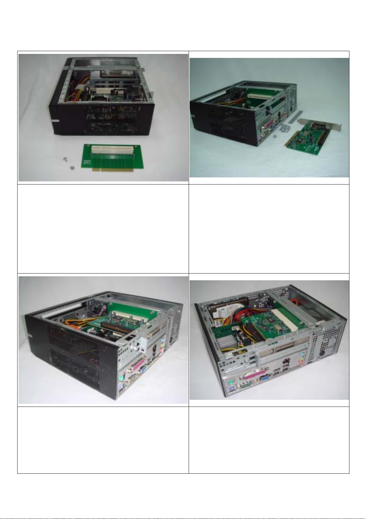
(2) To install the Riser Card, Break off and remove the ‘Punched-but-not-perforated’
Slot Cover (For Standard PCI Card) from the Rear Panel,
Unscrew and take out the Card Holder Bracket.
Insert the Riser Card into the Motherboard’s PCI Slot and,
Use 2 pcs of 6-32*L6 Hexagon Head Screws to secure the
Riser Card on the Center Bar.
(3) Insert your Expansion Card horizontally into the PCI Slot of
the Riser Card.
Fit back the Card Holder Bracket on the Rear Panel and, -
Use 1 pc of 6-32*L6 Hexagon Head Screw secure the Card
Holder Bracket on the Rear Panel.
(4) With Riser Card expansion system integration, 1 pc of 2.5" HDD is installable on the inner side of the Steel
Front Panel.
Note: This installation of the 2.5" HDD would obstruct and
invalidate the Card Reader integration.
Page 2
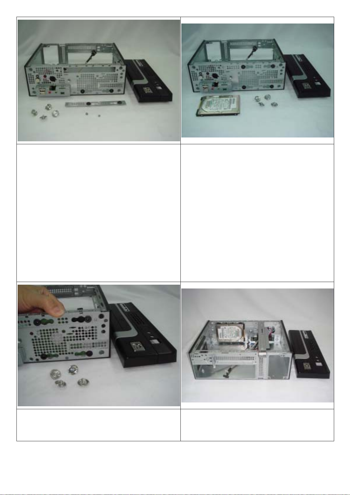
(5) To install the 2.5” HDD on the inner side of the Steel Front
(6) Use 2 pcs of 6-32*L4 Flat Head Screws to secure the
Panel –
First, dismantle the Front Panel from the Chassis Frame.
Take out the 2.5” HDD Fixture Bracket (S teel Bracket Cover for
the Slim ODD’s Inlet) from the Accessory Box,
Fit 2 pcs of Shockproof Rubber Cushions into the widest apart
Circular Holes of the 2.5” HDD Fixture Bracket.
Break off and remove the 3-Circular
‘Punched-but-not-perforated’ Covers on the Front Steel Panel
of the Chassis Frame and, -
Insert 2 pcs of Shockproof Rubber Cushions in the widest
apart holes.
2.5" HDD Fixture Bracket onto the Chassis Frame
(Blocking and covering the Slim ODD’s Inlet).
(7) Position the 2.5" HDD on the inner side of the Front Steel
Panel and align its bottom mounting screw holes.
(8) Take care to position the 2.5" HDD with its rear cable
connecting ports towards the Front I/O side.
Page 3
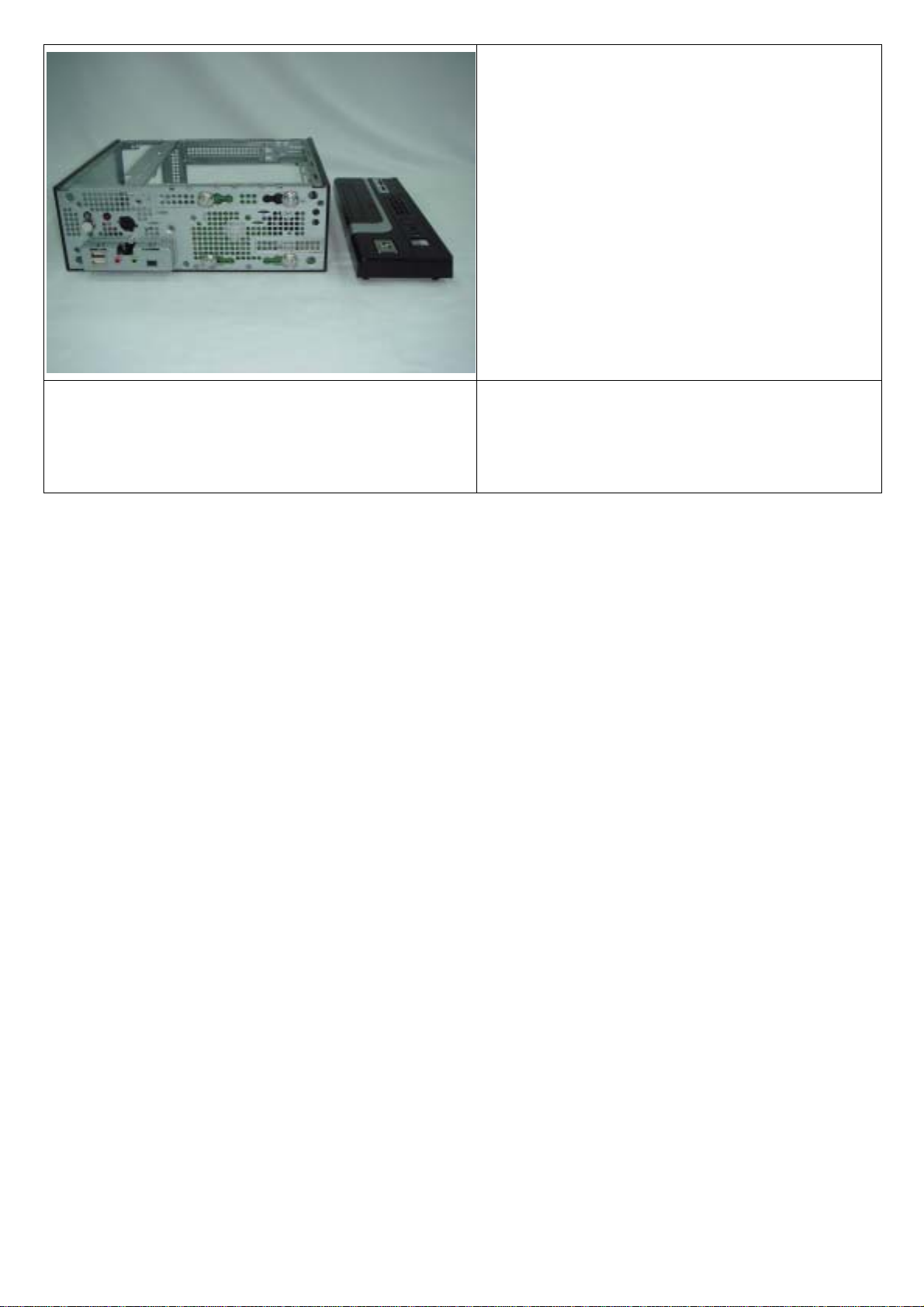
(9) Use 4 pcs of M3*0.5*L8 Hexagon Head Screws included
with EMI Clips to secure the 2.5" HDD on the Front S teel Panel
from the front to complete the installation.
Page 4

ECE0528i/ECE0548i Mini-ITX Chassis
3.5” HDD ASSEMBLY
(1) Before assembling the systems, -
Dismantle the Front Panel from the Chassis Frame,
Unscrew and remove the 3.5” HDD Bay (Including the 4 pcs of
Shockproof Rubber Cushions inserted in the 3.5” HDD Bay).
Take out the 2.5” HDD Bracket (Steel Bracket Cover for the
Slim ODD’s Inlet) from the Accessory Box and, Insert 2 pcs of Shockproof Rubber Cushions into the widest
apart Circular Holes.
(2) Use 2 pcs of 6#-32*L4 Flat Head Screws to –
Secure the 2.5” HDD Bracket onto the front steel panel of
the Chassis Frame (Covering the Slim ODD Inlet).
Use 4 pcs of Shockproof Rubber Cushions and EMI
Clipped M3*0.5*L8 Hexagon Head Screws to secure the
3.5” HDD in the 3.5” HDD Bay.
(3) Before installing back the Front Panel onto the Chassis, Secure the Slim ODD’s Plastic Bay Cover,
Seat the assembled 3.5” Drive Bay back into the Chassis,
Use 2 pcs of 6#-32*L4 Flat Head Screws to secure the 3.5”
HDD Bay on the Chassis Frame and then, -
Clip the Front Panel back into the Chassis Frame to complete.
.
Page 5

ECE0528i/ECE0548i Mini-ITX Chassis
ST ANDARD ASSEMBL Y
1. Before assembly, -
Dismantle the Plastic Slim ODD Cover from the Front Panel,
Remove the Slim ODD+2.5” Bay (Or 3.5" HDD Bay) and the
Center Bar from the Main Chassis Frame.
2. To install the bigger size FSP170-60SI/FSP220-6PLA
Power Supply, -
Break off and remove the excess
‘Punched-but-not-perforated’ Bracket on the Rear Panel
so that the Opening on the Rear Panel matches to the size
of the Power Supply.
(3) Place the Power Supply inside the case and, Use 3 pcs of 6-32*L6 Hexagon Head Screw to secure the
Power Supply from the Rear Panel.
(4) Use 4 pcs of 6-32*L6 Hexagon Head Screws to install
and secure the Motherboard.
If Low Profile Expansion Card is required, -
Unscrew and remove the Card Holder Bracket on the Rear
Panel,
Break off and remove the ‘Punched-but-not-perforated’
Low Profile Slot Cover on the Rear Panel.
Page 6

(5) Insert the Low Profile Expansion Card into the
(6) Fit back the Center Bar and secure it on the Main
Motherboard's Slot.
(7) The Slim ODD Bay is designed with a detachable 2.5" HDD
Bay to match multiple Motherboards’ systems.
Chassis Frame with 2 pcs of 6-32*L4 Flat Head Screws.
(8) Use 4 pcs of M2*0.4p*L3 Flat Head Screws to secure
the Slim ODD.
Use 4 pcs of M3*0.5p*L5 Flat Head Screws to secure the
2.5" HDD.
Page 7

(9) The Slim ODD Bay can be installed with, or without the 2.5”
(10) The 2.5" HDD Bay can be exempted for systems
HDD Bay. Above photo shows –
Slim ODD+2.5”HDD Bay installed with 2.5" HDD and, Slim ODD Bay only installed with 2.5” HDD.
(11) For the system integration of DC45FC Motherboard, -
integration of D201GLYA/D945GCLF/D945GCLF2
Motherboards. (Only the Slim ODD Bay is used)
(12) To exempt the use of the 2.5" HDD Bay and use only
The 2.5" HDD must be secured in the 2.5" HDD Bay and
Its position must be shifted to the right side of the Slim ODD
position (To avoid height obstruction with CPU Cooler).
the Slim ODD Bay, -
Use 4 pcs of M3*0.5p*L5 Flat Head Screws to secure the
2.5" HDD directly to the base of the Slim ODD Bay.
Page 8

(13) Seat the assembled Slim ODD Bay back into the case
(14) When only the Slim ODD Bay is used, there is internal
and, Use 2 pcs of 6-32*L4 Flat Head Screws to secure the Slim
ODD Bay onto the Center Bar and Main Chassis Frame.
(15) When both the Slim ODD+2.5” HDD Bay are used, -
space to allow the insertion of Low Profile Expansion Card.
(16) The use of both Slim ODD and 2.5" HDD Bay is
The 2.5” HDD would interfere with the Low Profile Expansion
Card (Space and construction limitation).
therefore, not capable to accommodate the Low Profile
Expansion Card systems.
 Loading...