

Page 1
www.jotron.com
Page 2

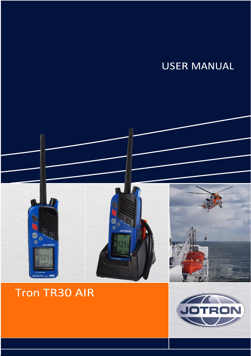
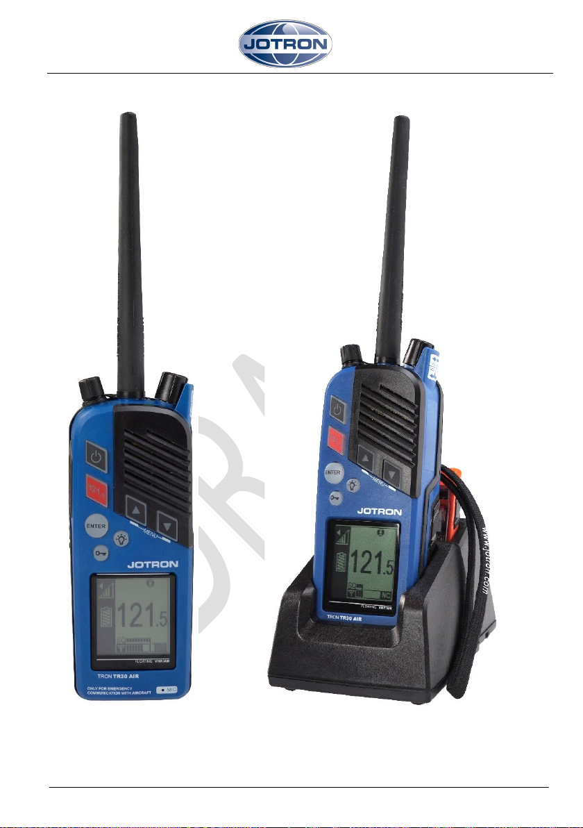
Tron TR30 AIR
2
Page 3

Tron TR30 AIR
CONTENTS
CONTENTS 3
1 GENERAL 5
2 IMPORTANT INFORMATION 6
3 PRODUCT DESCRIPTION 7
4 PRODUCT IMAGES 8
5 FUNCTIONAL DESCRIPTION 9
5.1 Tron TR30 AIR components 9
5.2 Antenna 10
5.3 Battery endurance 10
5.4 Emergency battery 11
5.5 Test battery 11
5.6 RH-30 Holder 11
6 INSTALLATION 13
6.1 Upon receipt of the radio 13
7 EMERGENCY USE 14
8 OPERATION INSTRUCTIONS 16
8.1 Turning on the radio 16
8.2 Channel selection 16
8.3 Channel 121.5MHz button 16
8.4 Volume adjustment 17
8.5 Squelch adjustment 17
8.6 Key lock and unlock 17
8.7 Menus 18
9 MAINTENANCE 21
9.1 Regular inspection 21
9.2 Regular testing 22
3
Page 4

Tron TR30 AIR
10 WARRANTY 23
10.1 COUNTERFEIT SPARE PARTS 23
10.2 Service agents 24
11 ACCESSORIES AND SPAREPARTS 25
11.1 Optional accessories 25
11.2 Spare parts 25
12 RECYCLING AND DISPOSAL 26
13 BATTERY SAFETY INSTRUCTIONS 27
13.1 HAZARD IDENTIFICATION 27
For complete Product Safety Data Sheet for battery cells, see 27
13.2 FIRST AID MEASURES 27
13.3 FIRE FIGHTING MEASURES 28
13.4 Handling and storage 28
13.5 Transportation 28
14 STANDARDS 29
15 ABBREVIATIONS 31
16 TECHNICAL SPECIFICATIONS 32
16.1 Product specification 32
17 TEST AND MAINTENANCE RECORDS 33
18 EMERGENCY INSTRUCTIONS 34
19 AMENDMENT RECORDS 35
4
Page 5
Tron TR30 AIR
1 GENERAL
Jotron manufactures safety equipment designed for the search and rescue of human life
and property. For safety equipment to be effective according to the design parameters it
is important that all products are handled, maintained, serviced and stowed in
compliance with this manual.
Copies of all Jotron documentation can be downloaded from our website:
www.jotron.com
All information contained within this manual has been verified and is to our knowledge
correct, however, Jotron reserves the right to make changes to any product(s) or
module(s) described herein to improve reliability, function or design, without further
notice.
The following three symbols are in use throughout this manual:
This symbol is used to highlight information.
.
This symbol is used to draw attention to important details
This symbol is used to highlight information that if not followed can
result in personal injury or body harm.
Jotron is not liable for consequential or special damages and cannot be held responsible
for any damages or injury arising either directly or indirectly due to an error or omission
of information, misuse of a product, breach of procedures, or for failure of any specific
component or other part of the equipment.
5
Page 6

Tron TR30 AIR
2 IMPORTANT INFORMATION
Below are instructions for keeping the radio log and the radio operator's obligation
according to national and international regulation:
1. The radio log shall be kept in accordance with requirements in the Radio
Regulation, SOLAS Convention, national regulations regarding radio installations
and the STCW Convention (STCW 95 including the STCW Code) including relevant
regulation regarding watch keeping on board passenger and cargo ships.
2. Unauthorized transmissions and incidents harmful interference should, if
possible, be identified, recorded in the radio log and brought to the attention of
the Administration in compliance with the Radio Regulations, together with an
appropriate extract from the radio log (STCW Code BVIII/2 No. 32).
6
Page 7

Tron TR30 AIR
3 PRODUCT DESCRIPTION
The Tron TR30 AIR is a ruggedly designed radio made for easy operation. It is a portable
emergency VHF radio for two-way communication between vessel and aircraft. The
radio is possible to operate using one hand, even when wearing gloves. The high
contrast graphical display including integrated back lighting of the display and keys are
very effective for visibility and usage in low light conditions.
It is also resistant to oil, seawater and sunlight. This radio is compact in size with smooth
edges to avoid damage to clothing or a raft.
The Tron TR30 AIR radio is waterproof down to 1 meter and floats in freshwater, battery
included. The radio is designed with a self-draining loudspeaker. The Tron TR30 AIR is
only waterproof when the antenna and jack cover are assembled on the radio correctly.
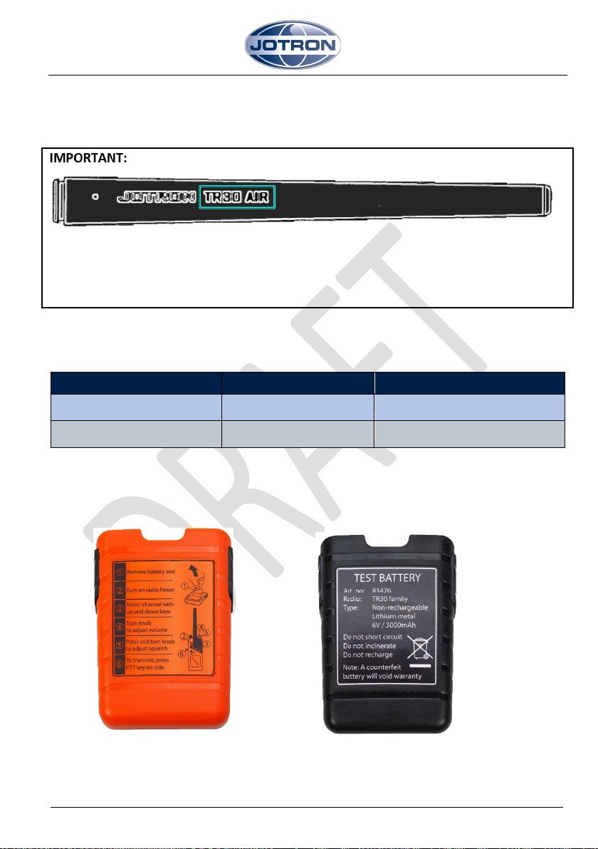
The Tron TR30 AIR package includes the following components:
• Tron TR30 AIR radio
• TR30 Emergency battery (orange)
• TR30 Test battery (black)
• RH-30 Holder
• Antenna
• Belt clip
• Wrist strap
• User Manual
Part number: 101700 Tron TR30 AIR
7
Page 8
Tron TR30 AIR
Figure 1 Tron TR30 AIR
4 PRODUCT IMAGES
8
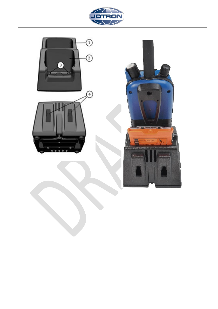
Figure 2 Tron TR30 AIR in RH-30 Holder
Page 9
Tron TR30 AIR
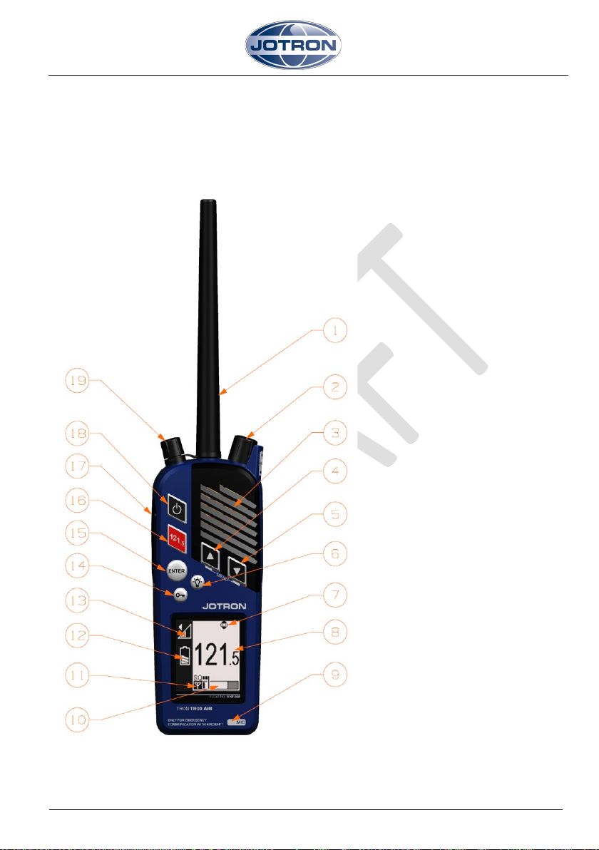
An overview of the radio components
1. Antenna TR30 AIR
5 FUNCTIONAL DESCRIPTION
5.1 Tron TR30 AIR components
2. Volume, squelch and
monitor control
3. Loudspeaker
4. Up button
5. Down button
6. Backlight button
7. Emergency mode indicator
8. Frequency indicator
9. Microphone
10. Squelch and signal
strength indicator
11. Transmitter power
indicator (only visible
when transmitting)
12. Battery status indicator
13. Volume control indicator
14. Key lock/unlock button
15. Enter button
16. 121.5 button (instant
access)
17. PTT transmit button
18. On/off button
19. Jack cover (external
Figure 3 Tron TR30 AIR components
accessories connector)
9
Page 10
Tron TR30 AIR
Battery
Standby hours at -20°C
Multi-usage at -20°C *
Figure 4 TR30 Emergency battery
5.2 Antenna
The antenna for the Tron TR30 AIR is fitted with a standard SMA connector. The antenna
shall be marked with “JOTRON TR30 AIR”.
Be sure to use correct antenna type. Antenna for Tron TR30 AIR, shall be marked with
TR30 AIR on side.
The Tron TR30 AIR unit is not waterproof when the standard antenna is not attached or
if the antenna is not assembled correctly.
5.3 Battery endurance
The standby and operation times of the batteries is listed below:
TR30 Emergency battery 60 hours >20 hours
TR30 Test battery 60 hours >20 hours
*Emergency battery lifetime hours have been tested in accordance with 10:10:80 ratio
(Send:Listen:Standby).
The two different batteries are shown below:
10
Figure 5 Test battery
Page 11

Tron TR30 AIR
5.4 Emergency battery
The Emergency battery (orange) is a lithium battery. This battery is specially designed for
use in distress situation and cannot be recharged. Keep the Emergency battery in the
RH-30 Holder, then it is easily accessible in a distress situation.
Always bring a sealed emergency battery with the radio when boarding a lifeboat or raft.
See chapter 15 for Battery safety instructions.
The emergency battery is a single use item. You must replace the
battery before the battery expiry date and/or if the protective seal on the battery is
broken.
New Emergency battery can be ordered from your local Jotron dealer or from
sale@jotron.com.
5.5 Test battery
Test battery shall be used for test and training.
New Test battery can be ordered from your local Jotron dealer or from
sale@jotron.com
Ensure you check the batteries for damage prior to use.
.
5.6 RH-30 Holder
The RH-30 Holder is a passive holder without any electronics or any charging possibility.
The holder has possibilities to store one radio with or without a Test battery, and an
Emergency battery.
Jotron recommend that the Test battery is always mounted on the radio when not in use
and stored in the RH-30 Holder. This will not drain the battery when the radio is turned
OFF
The RH-30 Holder can both be mounted on a horizontal or a vertical surface, see chapter
7.1 for details.
11
Page 12
Tron TR30 AIR
1. Battery storage bay
Figure 7 Tron TR30 AIR radio
and
Holder
An overview of the RH-30 Holder components:
Figure 6 RH-30 Holder components
2. Radio storage bay
3. Holes for horizontal mounting
(43mm spacing)
4. Holes for vertical mounting (36mm
spacing)
12
Emergency battery in
Page 13

Tron TR30 AIR
6 INSTALLATION
6.1 Upon receipt of the radio
Upon receipt of the radio, do the following:
1. Mount the RH-30 Holder. It can be mounted either on a horizontal or vertical
surface, using the respectively holes, see chapter 6.6. screw the RH-30 Holder to the
desired surface. The RH-30 Holder should be mounded in a place where it can be
easily accessible at all times.
2. Connect the antenna to the radio. When assembling the antenna to the radio,
ensure you hold it at the base while turning it clockwise. When the antenna starts to
resist turning, turn it another ¼ turn.
3. Mount the Test battery on the radio, preferable in dry environment.
4. Place emergency battery in the battery storage bay in the RH-30 Holder and the
radio in the radio bay.
The emergency battery should only be installed on the radio in a
Distress situation.
13
Page 14

Tron TR30 AIR
1. Pull back and remove the
7 EMERGENCY USE
To install the emergency battery on the Tron TR30 AIR, do the following:
emergency seal sticker on the
battery.
Rip the sticker off at the perforated edge.
2. Using the fixing track, mount the
GMDSS battery onto the back of
the radio.
Ensure you enter the bottom
14
edge of the battery into the
bottom edge of the radio. Do
not force the battery
Page 15

Tron TR30 AIR
3. Squeeze in the black finger grips
4. Turn on radio
5. Push PTT to transmit.
on either side of the battery to
lock the battery into place
15
Page 16

Tron TR30 AIR
8 OPERATION INSTRUCTIONS
The TR30 AIR shall only be used with Emergency battery, or Test battery. The Emergency
battery is for use in a distress situation. In case of a test or training, use a Test battery.
If the jack cover is removed, for example when using an accessory, the radio is no longer
waterproof.
The antenna, battery and jack cover must be correctly assembled on the radio in order
for it to be waterproof.
8.1 Turning on the radio
Press and hold the On/off button for approximately 3
seconds to turn the radio on.
The radio loads the following settings:
• Frequency 121.5MHz
• High volume
• Low squelch
8.2 Channel selection
Press the Up- or Down arrow buttons to change the frequency.
8.3 Channel 121.5MHz button
Press the 121.5 button to jump directly to
121.5MHz operating frequency.
16
Page 17

Tron TR30 AIR
8.4 Volume adjustment
Turn the volume control to adjust the volume.
The volume symbol in the display indicates the volume
level.
Ensure that you do not press down the volume control
while adjusting the volume.
8.5 Squelch adjustment
Press and turn the squelch control anti-
clockwise to increase receiver sensitivity.
The squelch bar appears on the screen display
indicating the current active sensitivity level.
When adjusted fully to the left, the squelch is
completely open. Adjusting to the right lowers
the receiver sensitivity.
The signal strength of the current channel appears on the bar below the squelch bar.
If the received signal is strong enough, the squelch opens and voice is received. This is
indicated by the Rx symbol.
When the squelch control is pressed twice, it opens the squelch immediately. Press
twice again to recall the previous squelch setting.
When the receiver signal is too distorted (by
radio noise) to be readable, the loudspeaker
or speaker mic is automatically muted. This is
indicated by the Noise Cancel (NC) symbol
that appears in the display
8.6 Key lock and unlock
Press and hold the Key lock/unlock button for 2
seconds to lock or unlock the buttons on the front
A key symbol appears when the radio is locked
PTT, Instant access 121.5MHz, volume and squelch
are still available when the radio is locked.
17
Page 18

Tron TR30 AIR
Press the Up- and Down arrow buttons at the same time to enter
8.7 Menus
or exit the menu system. Use the up/down arrow buttons to
navigate and select using Enter button.
Display screen:
Exit:
Menu
number:
Use this menu option to exit the menu system.
Settings:
Use this menu option to adjust the following
settings:
• Key sound
• Key volume
• Backlight time
• Backlight level
• Contrast
• Key lock time
Menu
number:
1
18
Page 19

Tron TR30 AIR
Key sound:
Menu
number:
Use this menu option to choose an audio
tone.
You can choose between four different tones.
Using the up/down arrow keys, select from 1-4.
Key volume:
Use this menu option to set the volume of the
key sound.
(Off=0, low to high=1-6)
Backlight level:
Use this menu option to set the display backlight
level.
(Off=0, low=1 or high=2)
1.1
Menu
number:
1.2
Menu
number:
1.3
Contrast:
Use this menu option to set the display
contrast level
(Low=1, medium= 2 or high=3)
Menu
number:
1.4
19
Page 20

Tron TR30 AIR
System:
Menu
number:
Use this menu option to access the following
information:
Serial Number
SW version
HW version
Serial Number:
Use this menu option to find the serial number of
the radio
SW Version:
Use this menu option to find the software
version of this radio.
2
Menu
number:
2.1
Menu
number:
2.2
Menu
HW Version:
Use this menu option to find the hardware
number:
2.3
version of this radio.
20
Page 21

Tron TR30 AIR
9 MAINTENANCE
The following maintenance should be completed.
If the radio is immersed in seawater, rinse it with fresh water immediately.
Wash away dirt and oil from the radio with warm water (no higher than 45 degrees
Celsius) and mild dish soap. Finish by rinsing with fresh water and drying.
This radio must never be opened by anyone other than an authorized
Jotron agent. Unauthorized disassembly will void your warranty.
9.1 Regular inspection
The lifetime of any equipment depends on how well you take care of it. The Tron TR30
AIR is constructed to endure in a rough maritime environment. Regular inspection is
important to detect error symptoms and prevent potentially serious problems.
To inspect, do the following:
1. Inspect the battery connection pins, the gasket and the lock/release device.
2. Inspect the housing for defects. This is important as defects can affect water sealing.
3. Ensure that the antenna and jack cover are assembled correctly, to keep the radio
waterproof.
21
Page 22

Tron TR30 AIR
9.2 Regular testing
It is important to perform regular testing to ensure proper operation. This ensures that
the radio is in good working order and ready for use in a potential distress situation.
Ensure you have a Test battery available for use during testing. The
Emergency battery should only be used in distress situations.
Testing should occur according to the requirements indicated in the on-board radio log.
To test, do the following:
1. Use the Test battery.
2. Turn the radio on and choose 123.1MHz. If you use test equipment connected
through the antenna connector, you may use 121.5MHZ.
3. Verify by sending and receiving a transmission. Use another radio, or your test
equipment.
4. Turn off the radio. Mount the antenna, if antenna has been removed during test.
5. Verify that the Emergency battery is still valid. The expiry date is located on the top
of the battery.
6. Verify that the Emergency battery is still sealed. If the seal is broken, replace the
battery immediately.
22
Page 23

Tron TR30 AIR
10 WARRANTY
The warranty period for a new Tron TR30 AIR is valid for 24 months from the date the
product is shipped from Jotron. If you have a product and are unclear about your
warranty period contact your sales partner.
All Jotron products are warranted against factory defects in materials and/or
workmanship during the warranty period, unless otherwise stated in writing. Please
refer to the terms and conditions of your sales agreement for additional information.
During this warranty period Jotron will repair or when necessary replace the product.
For updated warranty and service details see www.jotron.com
Support team at support@jotron.com
Keep the original packaging, as it is required if the product is shipped for
servicing. There are UN requirements in place for packaging and labelling when shipping
certain batteries as hazardous goods.
or contact Jotron
10.1 COUNTERFEIT SPARE PARTS
Jotron is aware of extended counterfeit spare parts being marketed and sold to fit
GMDSS safety products. It is of extreme importance that any spare parts being fitted to
this product are original spare parts, manufactured or approved by Jotron. Any use of
counterfeit spare parts will invalidate the product type-approval certificates and
warranty will not apply. Radio surveyor will also not approve and sign annual
performance tests for radios with counterfeit spare parts.
23
Page 24

Tron TR30 AIR
Jotron Group Head Office:
E-mail: sales@jotron.com
From 2020:
E-mail: sales@jotron.com
Jotron Group subsidiary companies:
Jotron UK Ltd.
E-mail: sales@jotron.com
Jotron Asia Pte. Ltd.
E-mail: sales@jotron.com
E-mail: sales@jotron.com
10.2 Service agents
Please look at: www.jotron.com for Maritime Service Agents.
Jotron AS
Østbyveien 1
NO-3280 Tjodalyng
Norway
Tel: +47 3313 9700
Fax: +47 3312 6780
Crosland Park
Cramlington
NE23 1LA
United Kingdom
Tel: +44 1670 712000
Fax: +44 1670 590265
Jotron USA, Inc.
10645 Richmond Avenue, Suite 170
Houston, TX 77042
USA
Tel: +1 713 268 1061
Fax: +1 713 268 1062
Jotron AS
Ringdalskogen
NO-3270 Larvik
Norway
Tel: +47 3313 9700
Fax: +47 3312 6780
19 Loyang Way, Changi
Logistics Centre
Rear Office Block #04-26
Singapore 508724
Tel: +65 65426350
Fax +65 65429415
24
Page 25

Tron TR30 AIR
11 ACCESSORIES AND SPAREPARTS
11.1 Optional accessories
For an overview of the available optional accessories for the Tron TR30 AIR, please refer
to our website.
11.2 Spare parts
For an overview of the available spare parts for the Tron TR30 AIR, please refer to our
website.
Ensure that all spare parts being fitted to the Tron TR30 AIR are
original spare parts manufactured or approved by Jotron.
Any use of counterfeit spare parts will deviate from the product type approval
certificates and warranty.
25
Page 26

Tron TR30 AIR
12 RECYCLING AND DISPOSAL
Tron TR30 AIR is not to be disposed as normal waste and must be handled in accordance
with the applicable federal, state and local waste disposal regulations in the country
where the equipment is used.
26
Page 27

Tron TR30 AIR
Product name:
TR30 Emergency battery/TR30 Test battery
Type no.:
FR6
Lithium metal content:
Below 1g per cell
Approximate weight:
100 grams
Chemical system:
Lithium/Iron Disulfide (Li/FeS2)
Designed for recharge:
No
Ingestion:
Do not induce vomiting or give food or drink. Seek medical
to find the contact information.
Inhalation:
Provide fresh air and seek medical attention.
Skin Contact:
Remove contaminated clothing and wash skin with soap
and water.
Eye Contact:
Immediately flush eyes thoroughly with water for at least 15
minutes, lifting upper and lower lids, until no evidence of the
13 BATTERY SAFETY INSTRUCTIONS
13.1 HAZARD IDENTIFICATION
The Lithium/Iron Disulfide batteries used in this product are sealed units which are not
hazardous when used according to the recommendations of the manufacturer. Under
normal conditions of use, the batteries are hermetically sealed.
For complete Product Safety Data Sheet for battery cells, see
http://data.energizer.com/pdfs/lithiumirondisulfide_psds.pdf
Do not short circuit, charge, puncture, incinerate, crush, immerse, force
discharge or expose to temperatures above the declared operating
temperature range of the product, otherwise you risk fire or explosion.
Ingestion: Swallowing a battery can be harmful.
Inhalation: Contents of an open battery can cause respiratory irritation.
Skin Contact: Contents of an open battery can cause skin irritation.
Eye Contact: Contents of an open battery can cause severe irritation.
13.2 FIRST AID MEASURES
attention immediately.
In USA:
call National Battery Ingestion Hotline (202-625-3333).
For other countries:
http://www.who.int/gho/phe/chemical_safety/poisons_centres
27
Page 28

Tron TR30 AIR
chemical remains. Seek medical attention.
13.3 FIRE FIGHTING MEASURES
In case of fire where lithium batteries are present, flood area with water or smother
with a Class D fire extinguishant appropriate for lithium metal, such as Lith-X. Water
may not extinguish burning batteries but will cool the adjacent batteries and control
the spread of fire. Burning batteries will burn themselves out. Virtually all fires
involving lithium batteries can be controlled by flooding with water. However, the
contents of the battery will react with water and form hydrogen gas. In a confined
space, hydrogen gas can form an explosive mixture. In this situation, smothering
agents are recommended. A smothering agent will extinguish burning lithium
batteries.
Emergency Responders should wear self-contained breathing apparatus. Burning
lithium-iron disulfide batteries produce toxic and corrosive lithium hydroxide fumes
and sulfur dioxide gas.
13.4 Handling and storage
The Tron TR30 AIR should be stored in a cool and well ventilated area. Elevated
temperatures can result in a reduction of battery life. In locations that handle large
quantities of lithium batteries, such as a warehouse, lithium batteries should be isolated
from unnecessary combustibles.
A battery that is disassembled or exposed to water, fire or high
temperatures can explode or leak, causing burns.
13.5 Transportation
Detailed support documentation regarding transportation regulations for batteries in
accordance with ICAO/IATA, IMDG code and/or ADR/RID can be found at
www.jotron.com
accordance with UN test 38.3
28
, under Product Safety Information (PSI) and/or statement in
Page 29

Tron TR30 AIR
FCC 47 CFR Part 2. 87
FCC 47 CFR Part 2.
IEEE 1528 (2013)
14 STANDARDS
Jotron declares that this radio is in compliance with Radio Equipment Directive
2014/53/EU. A copy of the declaration of conformity can be downloaded from the
Jotron website.
The Tron TR30 AIR has been verified, tested and meets the following product standards:
EN/IEC 60945: 2002
including Corr.1
(Category - Portable)
ETSI EN 301 688 V1.2.1
ETSI EN 301 489-22 Electromagnetic compatibility and Radio spectrum
1093
IEC 60529:1989 Degrees of protection provided by enclosures (IP Code).
IEC 62368-1:2018 Audio/video, information and communication technology
Maritime navigation and radio communication equipment
and systems - General requirements - Methods of testing
and required test results.
Technical characteristics and methods of measurement
for fixed and portable VHF equipment operating on 121,5
MHz and 123,1 MHz.
Matters (ERM);
Electromagnetic Compatibility (EMC) standard for radio
equipment and services;
Part 22: Specific conditions for ground based VHF
aeronautical mobile and fixed radio equipment.
Aviation Services
Radiofrequency radiation exposure evaluation: portable
devices.
Part 2 - Frequency allocations and radio treaty matters;
general rules and regulations
equipment - Part 1: Safety requirements.
ANSI/IEEE Std. C95.1
(1999)
Standard for Safety Levels with Respect to Human
Exposure to Radio Frequency Electromagnetic Fields, 3
kHz to 300 GHz
Recommended Practice for Determining the Peak SpatialAverage Specific Absorption Rate (SAR) in the Human
Head from Wireless Communications Devices:
Measurement Techniques.
29
Page 30

Tron TR30 AIR
RSS-102 Issue 5 Safety
47 CFR 80 to End: Mar.
2019
Electronic Code of Federal Regulations, Title 47,
Telecommunications.
47 CFR 2: Mar. 2019 Electronic Code of Federal Regulations, Title 47,
Telecommunications.
EN 50566:2017
Product standard to demonstrate the compliance of
wireless communication devices with the basic
restrictions and exposure limit values related to human
exposure to electromagnetic fields in the frequency range
from 30 MHz to 6 GHz: hand-held and body mounted...
EN/IEC 62209-1:2016 Measurement procedure for the assessment of specific
absorption rate of human exposure to radio frequency
fields from hand-held and body-mounted wireless
communication devices - Part 1: Devices used next to the
ear (Frequency range of 300 MHz to 6 GHz).
EN/IEC 62209-2
Ed.1(2010)
Human exposure to radio frequency fields from hand-held
and body-mounted wireless communication devices Human models, instrumentation, and procedures - Part 2:
Procedure to determine the specific absorption rate (SAR)
for wireless communication devices used in close
proximity to the human body (frequency range of 30 MHz
to 6 GHz).
Radio Frequency (RF) Exposure Compliance of
Code (2015)
Radiocommunication Apparatus (All Frequency Bands)
This device complies part 80 of the FCC Rules.
Any changes or modifications not expressly approved by the party responsible for
compliance could void the user's authority to operate this equipment.
This class 2 CE approved product is available for sale and purchase in the following
countries: Brazil, Canada, China, Europe, Korea, Russia and the United States of America.
The relevant CE marking of CE0470 is found on the product and the packaging.
All statements of conformity are available at:
Regulations for VHF radios varies from country to country. Prior to
using this equipment check the national requirements for VHF radio operators and
ensure that the radio conforms to all local regulations.
30
www.jotron.com
Page 31

Tron TR30 AIR
ADR
European Agreement concerning the International Carriage of Dangerous
Goods by Road
AM
CFR
Amplitude Modulation
The Code of Federal Regulations
DC
EMC
Direct Current
Electromagnetic compatibility
ERM
Electromagnetic compatibility and Radio spectrum Matters
ETS
European Telecommunications Standard
ETSI
GHz
European Telecommunications Standards Institute
Giga Hertz
GMDSS
Global Maritime Distress and Safety System
HW
Hardware
IATA
International Air Transport Association
ICAO
International Civil Aviation Organization
IEC
International Electrotechnical Commission
IMDG
International Maritime Dangerous Goods Code
IP Code
MHz
International Protection Marking, IEC standard 60529
Mega Hertz
MSDS
Material Safety Data Sheet
OSHA
Occupational Safety and Health Admin
PTT
Push to talk
RF
Radio Frequency
Dangerous Goods by Train)
SDS
Safety Data Sheet
SINAD
SMA
SIgnal-to-(Noise And Distortion) ratio
Sub miniature version A connector
SOLAS
Safety of Life at Sea (An international maritime safety treaty)
STCW
Standards of training, certification and watch keeping for seafarers
SW
Software
UN
United Nations
VHF
Very High Frequency
15 ABBREVIATIONS
CE
FCC
FM
kHz
LiFeS2
Conformité Européenne (European Conformity)
Federal Communications Commission
Frequency Modulation
Kilo Hertz
Lithium Iron Disulfide
RID
Règlement concernant le transport International ferroviaire des
merchandises Dangereuses par chemin de fer (Transportation of
31
Page 32

Tron TR30 AIR
Parameters
TR30 AIR Specification
16 TECHNICAL SPECIFICATIONS
16.1 Product specification
Operating temperature range: -20°C to +55°C (-4°F to +131°F)
Size (WxHxD):
Full buoyancy: Yes
Weight: Approximately 300 g (incl. battery)
Receiver:
Frequency, 2 channels: 121.5 MHz, 123.1 MHz
Modulation: AM
Channel spacing: 25 kHz
Maximum usable sensitivity: < 2 µV for 12dB SINAD (Typ. 1 µV)
Adjacent channel rejection: > 70 dB
Spurious response: > 70 dB
Harmonic distortion: < 5% (Typ. 2%)
Internal speaker output power: >200 mW (Typ. 350 mW)
Speaker mic output power 15 mW (8 Ω)
Transmitter:
61 mm x 157 mm x 40 mm (Depth with belt clip 47
mm)
Frequency, 2 channels: 121.5 MHz, 123.1 MHz
Channel spacing: 25 kHz
Transmitter output power: 0.25 W (DC), PEP<1 W
Modulation AM: >70%
Harmonics and spurious: < 0.25 µW
Frequency error: < +/-500 Hz
32
Page 33

Tron TR30 AIR
Date
B/N/T*
Signature
Insp
17 TEST AND MAINTENANCE RECORDS
Below is an overview of all test and control details.
*B=New battery, N=New Tron TR30 AIR, T=Test.
33
Page 34

Tron TR30 AIR
18 EMERGENCY INSTRUCTIONS
34
Page 35

Tron TR30 AIR
Vers
Date
Reason
By
19 AMENDMENT RECORDS
A 20.Mar.2019 First revision of manual. AF
35
Page 36

Tron TR30 AIR
36
Page 37

Tron TR30 AIR
37
 Loading...