


USER MANUAL
Tron TR30


Table of contents
1 Listof figures 8
2 Abbreviations 9
3 General 11
4 Standards 13
5 Product description 18
5.1 Productimage 20
6 Battery safety instructions (GMDSS radio) 22
6.1 Hazardsidentification 23
6.2 First aidmeasures 24
6.3 Firefightingmeasures 24
6.4 Accidentalreleasemeasures 25
6.5 Handlingand storage 26
6.5.1 Transportation 26
7 Battery safety instructions(Maritime VHF radio) 27
7.1 Hazards identification 28
7.2 First aidmeasures 29
7.3 Firefightingmeasures 29
7.4 Accidentalreleasemeasures 30
Page- 3 -

7.5 Handlingand storage 31
7.5.1 Transportation 31
8 Functionaldescription 32
8.1 TronTR30components 32
8.2 Antenna 34
8.3 Batteryendurance 34
8.4 Emergency battery 35
8.5 Rechargeablebattery 36
8.6 RCH-30Battery charger 37
8.6.1 RCH-30Battery charger components 39
8.6.2 MountingtheRCH-30 Battery charger 41
8.6.3 LED indicator 42
9 Technical specifications 43
9.1 Product specification 43
10 Installation 45
Page- 4 -
10.1 Upon receiptof the radio 45
10.2 In an emergency situation 46
10.3 Replacingthe emergency battery 48
10.4 Installingthe rechargeablebattery 48

10.5 Changingthe rechargeablebattery 49
11 Operationinstructions(GMDSS radio) 51
11.1 Emergencymode 51
11.2 Channelselection 52
11.3 Channel16button 53
11.4 Volume adjustment 53
11.5 Squelchadjustment 54
11.6 Key lock andunlock 55
11.7 Watch 55
11.7.1 Dual watch 56
11.8 Menus 57
12 Operationinstructions (Maritime VHF radio) 62
12.1 Regularradiomode 62
12.2 Channelselection 63
12.3 Channel16button 63
12.4 Callchannel 64
12.5 Custom channels 65
12.6 Volumeadjustment 66
12.7 Squelchadjustment 66
Page- 5 -

12.8 Key lock andunlock 68
12.9 Watch 68
12.9.1 Dualwatch 69
12.9.2 Triple watch 70
12.9.3 Scan 71
12.9.3.1 ScanProg 72
12.10 Menus 73
12.11 Externalaccessories 80
13 Maintenance 82
13.1 Regular inspection 82
13.2 Regular testing 83
14 Test andmaintenance records 85
15 Channels andfrequencies 86
15.1 GMDSS 87
15.2 Canada 88
Page- 6 -
15.3 International 89
15.4 USA 90
16 Warranty 91
16.1 Warranty claims 92

16.2 Service 92
16.3 Serviceagents 93
17 Optionalaccessories 95
18 Spare parts 96
19 Recyclinganddisposal 97
20 Emergency instructions 98
Page- 7-

1 List of figures
Figure 1 Tron TR30 20
Figure 2 TronTR30in the RCH-30Battery charger 21
Figure 3 Tron TR30components 32
Figure 4 RCH-30Batterycharger- chargingandstoragebays 38
Figure 5 Radio in the chargingbay andGMDSS battery in the storagebay 38
Figure 6 RCH-30Battery charger components 40
Figure 7 Emergencyinstructionsoverview 98
Page- 8 -

2 Abbreviations
ADR EuropeanAgreementconcerningthe InternationalCarriage of
Dangerous Goods by Road
CFR TheCode of FederalRegulations
DW DualWatch(Receiver altering betweentwo different channels)
ECHA EuropeanChemicalAgency
EMC Electromagnetic compatibility
ESD Electrostatic discharge
ETS EuropeanTelecommunicationsStandard
ETSI EuropeanTelecommunicationsStandardsInstitute
GMDSS Global MaritimeDistress andSafety System
HW Hardware
IATA InternationalAir Transport Association
ICAO InternationalCivilAviationOrganization
IEC InternationalElectrotechnical Commission
IMDG InternationalMaritime Dangerous Goods Code
MHz MegaHertz
MSDS MaterialSafety DataSheet
NC Noise cancel
OSHA OccupationalSafety andHealthAdmin
PTT Pushto talk
RES Radio equipmentandsystems (technical committee of ETSI)
RID Reglementconcernant letransport Internationalferroviaredes
merchandisesDangereusesparcheminde fer (Transportation of
Dangerous Goods by Train)
Page- 9 -

RMA ReturnMaterialAuthorizationnumber
RSS RadioStandards Specification
SDS Safety DataSheet
SMA Subminiatureversion A connector
SOLAS Safety of Life at Sea (An internationalmaritime safety treaty)
STCW Standardsof training,certification andwatch keepingfor seafarers
SW Software
TW TripleWatch
UN United Nations
VAC Volts,alternatingcurrent(AC)
VHF Very HighFrequency
Page- 10-

3 General
Jotron manufacturessafety equipment designedfor the searchandrescueof humanlife and
property.For safety equipmentto beeffective according to the designparameters it is
imperative that allproductsarehandled, maintained,serviced andstowed in compliancewith the
manufacturer's instructions.
Copiesof allJotrondocumentation can be downloadedfrom our website:www.jotron.com.
Allinformationcontainedwithin this manualhasbeenverifiedandis to our knowledgecorrect,
however,Jotron reserves therightto make changes to any product(s) or module(s)described
hereinto improve reliability,function or design,without furthernotice.
Thefollowingfour symbolsarein use throughoutthismanual:
Thissymbol is usedto highlight information.
Thissymbol is usedto drawattentionto importantdetails.
Page- 11 -
Thissymbol is usedto highlight informationthatif not followedcanresultin
damage to a productor equipment.
Thissymbol is usedto highlight informationthatif not followedcanresultin
personalinjury or bodily harm.
Jotron is not liablefor consequentialor special damagesandcannot beheld
responsible for any damagesor injury arising eitherdirectly or indirectly due
to anerror or omission of information,misuseof a product,breachof
procedures,or for failure of any specificcomponent or other part of the
equipment.
Page- 12 -

4 Standards
Jotron declares that this radio is incompliancewith Directive 2014/53/EU. A copy of the
declaration of conformity canbedownloadedfrom the Jotron website.
TheTron TR30(emergencymode- GMDSS) hasbeenverified,testedandmeets the following
product standards:
EN/IEC 60945: 2002 includingCorr.1
(Category - Portable)
ETSI EN300225, V1.4.1(2004-12) Electromagnetic compatibility andRadiospectrum
ETSI EN301 843-1, V1.2.1 (2004-06) Electromagnetic compatibility andRadiospectrum
ETSI EN301 843-2, V1.2.1 (2004-06) Electromagnetic compatibility andRadiospectrum
IEC 61097-12:1996 Globalmaritime distress and safety system (GMDSS) -
Maritime navigation andradiocommunication
equipment andsystems - Generalrequirements Methods of testing andrequired test results
Matters (ERM);Technicalcharacteristics andmethods
of measurement for survivalcraft portableVHF
radiotelephoneapparatus
Matters (ERM);ElectroMagneticCompatibility(EMC)
standardfor marine radio equipment andservices;Part
1:Common technicalrequirements
Matters (ERM);ElectroMagneticCompatibility(EMC)
standardfor marine radio equipment andservices;Part
2:Specificconditions for VHF radiotelephone
transmitters and receivers
Part 12: Survivalcraft portabletwo-way VHF
radiotelephoneapparatus - Operationaland
performance requirements,methods of testingand
Page- 13 -

requiredtest results
RSS-102,Issue5: Mar.2015 Radio Frequency (RF) Exposure Complianceof Radio
communicationApparatus (AllFrequency Bands)
RSS-182,Issue 5:Jan.2012 Maritime Radio TransmittersandReceivers intheBand
156-162.5 MHz
Tron TR30(regularmode - VHF) has beenverified,testedandmeets thefollowingproduct
standards:
EN62479:2010 Assessment of the complianceof low power electronic
andelectrical equipment withthebasic restrictions
relatedto humanexposureto electromagnetic fields (10
MHz to 300 GHz)
ETSI EN301 178,V2.2.2(2017-04)
ETSI EN 301 178 V2.2.2 (2017-04) Portable
Very High Frequency (VHF) radiotelephone
equipment for the maritime mobile service
operating in the VHF bands (for non-GMDSS
applications only); Harmonised Standard
covering the essential requirements of article
3.2 of Directive 2014/53/EU
ETSI EN301 178-1,V1.3.1: 2007-02 Electromagneticcompatibility andRadio spectrum
Matters (ERM);Portable Very HighFrequency (VHF)
radiotelephoneequipment for the maritime mobile
serviceoperatinginthe VHF bands(for non-GMDSS
applications only);Part1: Technical characteristicsand
methodsof measurement
ETSI EN301 178-2, V1.2.2:2007-02 Electromagnetic compatibility andRadiospectrum
Matters (ERM);Portable Very HighFrequency (VHF)
radiotelephoneequipment for the maritime mobile
Page- 14 -

serviceoperatinginthe VHF bands(for non-GMDSS
applications only);Part2: Harmonized EN covering
essential requirements of article 3.2 of the R&TTE
Directive
ETSI EN301 843-1, V1.2.1 (2012-08) Electromagneticcompatibility andRadio spectrum
Matters (ERM);ElectroMagneticCompatibility(EMC)
standardfor marine radio equipment andservices;Part
1:Common technicalrequirements
ETSI EN301 843-2, V1.2.1 (2004-06) Electromagnetic compatibility andRadiospectrum
Matters (ERM);ElectroMagneticCompatibility(EMC)
standardfor marine radio equipment andservices;Part
2:Specificconditions for VHF radiotelephone
transmitters and receivers
IEC 62209-1:2005 Human exposure to radio frequency fieldsfrom hand-
held andbody-mountedwireless communication
devices - Humanmodels,instrumentation,and
procedures - Part 1: Procedure to determinethe specific
absorptionrate(SAR) for hand-helddevices used in
closeproximity to the ear(frequency rangeof 300 MHz
to 3 GHz)
IEC 62209-2: 2010 Humanexposureto radiofrequency fieldsfrom hand-
held andbody-mountedwireless communication
devices - Humanmodels,instrumentation,and
procedures - Part 2: Procedure to determine the
specific absorptionrate(SAR) for wireless
communicationdevices used in close proximity to the
humanbody(frequency rangeof 30 MHz to 6 GHz)
IEC 62368-1:2014 Audio/video,informationandcommunication
technology equipment - Part 1: Safety requirements
Page- 15 -
Theuse of TronTR30radio withtherechargeable LiPo battery may be
subject to anoperator certificateinaccordancewithRED 2014/53/EU,
Article 10.10.
Prior to usingthisequipment,please check withyour localnationalradio
licenseauthority.
47 CFR 2.1093:Oct. 2013 Radio frequency radiation exposure evaluation:portable
devices.
47 CFR 80 to End:Oct. 2015 ElectronicCode of FederalRegulations,Title47,
Telecommunications
Thisdevicecomplies withtheGMDSS provision of part 80 of the FCC Rules.
Any changes or modifications not expressly approved by the party
responsible for compliance could voidtheuser's authority to operatethis
equipment.
Thisclass 2 CE approvedproductis availablefor saleandpurchaseinthe
followingcountries:
Page- 16-
Brazil,Canada,China,Europe,Korea, Russiaand the United States of
America.
Therelevant CE marking of CE0168!is foundon theproductandthe
packaging.
Allstatements of conformity areavailable at: www.jotron.com
Page- 17-

5 Product description
TheTron TR30isa ruggedly designedradio madefor easy operation.It isa portablesurvivalcraft
two-way VHF radio which is possibleto operate usingone hand, even whenwearing gloves.The
highcontrast graphicaldisplay includingintegrated backlighting of the display andkeys are very
effective for visibility andusagein low light conditions.
It isalsoresistant to oil,seawaterandsunlight.Thisradio is compactinsizewith smooth edgesto
avoiddamage to clothingor a raft.The highly visibleorangehousingismade from glass
reinforcedpolycarbonate.
TheTron TR30 GMDSS (emergency mode) radio iswaterproof down to 1 meter and floatsin
freshwater,battery included.The radio is designedwitha self drainingloudspeaker. The Tron TR30
isonly completely waterproof whentheantennaandjack cover are assembledon theradio
correctly.
TheTron TR30(GMDSS - emergency mode) radio includes thefollowingcomponents:
• TronTR30radio
• Emergency GMDSS battery (orange)
• Antenna
• Belt clip
• Wrist strap
Part number:83446 Tron TR30 GMDSS
TheTron TR30Maritime VHF radio(regular mode) includesthe followingcomponents:
Page- 18 -

• TronTR30radio
• Emergency GMDSS battery (orange)
• Rechargeablebattery(black)
• Battery charger
• Antenna
• Belt clip
• Wrist strap
Part number:87950Tron TR30GMDSS andMaritime VHF radio
Page- 19-
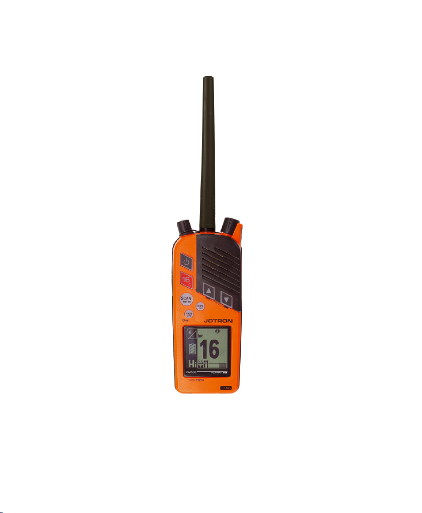
5.1 Product image
Figure 1 Tron TR30
Page- 20 -

Figure 2 TronTR30in the RCH-30Battery charger
Page- 21 -

6 Battery safety instructions
(GMDSS radio)
UnderEC, EuropeanChemicalAgency (ECHA) and US,OccupationalSafety andHealthAdmin
(OSHA) legislation this product is classifiedasa manufacturedarticle,whichdoes not release or
otherwiseresult in exposure to ahazardouschemicalunder thenormal conditions of use.
Therefore,thisproductisexempt from therequirement of a dedicatedMaterialSafety Data
Sheet(MSDS) or Safety DataSheet(SDS).
Thefollowinginformationis includedinthismanualas guidedsafety instructions.
Productname: Emergencybattery
Typeno.: FR6
Lithium metalcontent: 2 x 1.96 gram lithium prbattery
Approximate weight: 100grams
Chemicalsystem: Lithium Iron Disulphide
Designedfor recharge: No
Below are instructions for keepingtheradiolog andthe radio operator's obligation accordingto
nationaland internationalregulation:
1. Theradiolog shallbe kept inaccordance withrequirementsinthe Radio Regulation,SOLAS
Convention,nationalregulations regardingradioinstallations andthe STCW Convention
(STCW 95 including the STCW Code)includingrelevant regulation regardingwatch keeping
on board passenger andcargo ships.
Page- 22 -
2. Unauthorizedtransmissions andincidentsharmful interferenceshould,if possible, be
identified,recordedintheradiolog andbroughtto theattentionof theAdministration in
compliancewith the Radio Regulations,together withanappropriateextractfrom the radio
log(STCW Code BVIII/2 No. 32).
Testingof radio equipmentandreservesource of energyshouldoccur:
Thebelowsafety informationis extractedfrom EVE Energy SDS (sections4,
5 and6).
6.1 Hazards identification
Thelithium iron disulphide batteries used in the Tron TR30 and describedhereinaresealedunits.
Undernormal conditions, the battery ishermeticallysealed.Thesebatteriesare not hazardous
whenusedasintendedandrecommended.
Do not short circuit,puncture,incinerate,crush,immerse,force discharge or
exposeto temperatures above thedeclaredoperatingtemperature range
of the product,otherwiseyou riskfire or explosion.
Page- 23 -
Ingestion: Swallowinga battery can beharmful.
Inhalation: Contentsof an openbattery cancauserespiratory
irritation.
Skincontact: Contentsof an open battery can causeskin
irritation.
Eye contact: Contents of an open battery can cause severe
irritation.
6.2 First aid measures
Ingestion: Do not inducevomitingor consume food or drink.
Seekmedicalattention immediately.
Inhalation: Providefreshairandseekmedicalattention.
Skincontact: Remove contaminatedclothingandshoesandwash
skin withsoapandwater.Washclothingand shoes prior
to reuse. If irritationoccurs, seek medicalattention.
Eye contact: Immediatelyflusheyes thoroughly with waterfor at
least 15 minutes,lifting upperandlower lids,untilno
evidenceof thechemicalremains.Seek medical
attention.
6.3 Fire fighting measures
In case of firewhere lithium batteriesarepresent, floodarea with wateror smotherwith a ClassD
fire extinguisher appropriate for lithium metal, such as Lith-X. Water may not extinguishburning
Page- 24 -
batteriesbutwillcool the adjacent batteries andcontrol spreadingfire. Burningbatterieswillburn
themselves out.
Virtually allfiresinvolving lithium batteriescanbe controlledby flooding with water,however,the
contents of the battery will react withwater andform hydrogengas.In a confinedspace,
hydrogen gas can form an explosive mixture.In this situation,a smothering agentis
recommended.A smothering agentwillextinguishburninglithium batteries.
Any person respondingto suchan emergency should wear a self-contained
breathing apparatus.
Burninglithium iron disulphide batteries producestoxic andcorrosive lithium
hydroxide fumes andsulfur dioxidegas.
6.4 Accidental release measures
To clean up aleakingbattery:
Ventilationrequirements: Room ventilationmay bein areaswhere thereareopen
or leaking batteries.
Respiratory protection: Avoidexposureto electrolytefumes from an open or
leakingbattery.
Eye protection: Wearsafety glasseswith sideshieldsif handlinganopen
or leaking battery.
Gloves: Use neopreneor natural rubbergloveswhen handling
anopenor leakingbattery.Battery materialsshouldbe
disposedof in a leak-proof container.
Page- 25 -
6.5 Handling and storage
TheTron TR30should be storedina cool and well ventilatedarea.Elevatedtemperatures can
result ina reductionof batterylife.In locationsthathandlelargequantities of lithium batteries,
suchas a warehouse,lithium batteries shouldbe isolated from unnecessary combustibles.
A battery that is disassembledor exposedto water,fire or hightemperatures
canexplode or leak causing burns.
6.5.1 Transportation
Detailedsupport documentationregardingtransportation regulationsfor
batteriesinaccordance withICAO/IATA, IMDG code and/or ADR/RID can
befound at www.jotron.com,under Product Safety Information(PSI)
and/or statementinaccordance withUN test38.3
Page- 26 -

7 Battery safety instructions
(Maritime VHF radio)
UnderEC, EuropeanChemicalAgency (ECHA) and US,OccupationalSafety andHealthAdmin
(OSHA) legislation this product is classifiedasa manufacturedarticle,whichdoes not release or
otherwiseresult in exposure to ahazardouschemicalunder thenormal conditions of use.
Therefore,thisproductisexempt from therequirement of a dedicatedMaterialSafety Data
Sheet(MSDS) or Safety DataSheet(SDS).
Thefollowinginformationis includedinthismanualas guidedsafety instructions.
Productname: Rechargeablebattery (LiPo 1550 mAh)
Typeno.: GEP653759
Lithium metalcontent: 0.9gram lithium pr batteryand11.5 watt-hour rating
(Wh)
Approximate weight: 100grams
Chemicalsystem: Lithium Polymer
Designedfor recharge: Yes
Below are instructions for keepingtheradiolog andthe radio operator's obligation accordingto
nationaland internationalregulation:
1. Theradiolog shallbe kept inaccordance withrequirementsinthe Radio Regulation,SOLAS
Convention,nationalregulations regardingradioinstallations andthe STCW Convention
(STCW 95 including the STCW Code)includingrelevant regulation regardingwatch keeping
on board passenger andcargo ships.
Page- 27-
2. Unauthorizedtransmissions andincidentsharmful interferenceshould,if possible, be
identified,recordedintheradiolog andbroughtto theattentionof theAdministration in
compliancewith the Radio Regulations,together withanappropriateextractfrom the radio
log(STCW Code BVIII/2 No. 32).
Testingof radio equipmentandreservesource of energyshouldoccur:
Monthly: HandheldVHF transceivers areto be testedusinga test or rechargeablebattery.
Thebelowsafety informationis extractedfrom Green Energy Batteryand
MSDS info from Pony Test Lab's report (sections 4,5 & 6).
7.1 Hazards identification
Thelithium polymer batteriesusedinthe Tron TR30anddescribedherein are sealedunits.
Undernormal conditions, the battery ishermeticallysealed.Thesebatteriesare not hazardous
whenusedasintendedandrecommended.
Page- 28 -
Do not short circuit,puncture,incinerate,crush,immerse,force discharge or
exposeto temperatures above thedeclaredoperatingtemperature range
of the product,otherwiseyou riskfire or explosion.
Ingestion: Swallowinga battery can beharmful.
Inhalation: Contentsof an openbattery cancauserespiratory
irritation.
Skincontact: Contentsof an open battery can causeskin
irritation.
Eye contact: Contents of an open battery can cause severe
irritation.
7.2 First aid measures
Ingestion: Do not inducevomitingor consume food or drink.
Seekmedicalattention immediately.
Inhalation: Providefreshairandseekmedicalattention.
Skincontact: Remove contaminatedclothingandshoesandwash
skin withsoapandwater.Washclothingand shoes prior
to reuse. If irritationoccurs, seek medicalattention.
Eye contact: Immediatelyflusheyes thoroughly with waterfor at
least 15 minutes,lifting upperandlower lids,untilno
evidenceof thechemicalremains.Seek medical
attention.
7.3 Fire fighting measures
In case of firewhere lithium batteriesarepresent, use anextinguishingagent suitable for the
location andsurroundingenvironment, such as CO₂.
Page- 29 -

A battery may burstandreleasehazardousdecomposition products whenexposedto fire.
Lithium polymer batteries containflammableelectrolytethatmay vent,igniteandproduce
sparks whensubjectedto hightemperatures(›150°C/302°F),whendamaged or abused(e.g.
mechanicaldamage or electricalovercharging), may burn rapidly withflare-burningeffect;may
igniteother batteries in close proximity.
Any person respondingto suchan emergency should wear a self-contained
breathing apparatus.
Burninglithium polymer batteriesproducestoxic and corrosive lithium
hydroxide fumes andsulfur dioxidegas.
7.4 Accidental release measures
Personalprecautions: Wearthe proper personalprotectiveequipment.Keep
unprotectedindividuals away.Ensure adequate
ventilation.
Emergencyprocedures: Remove ignitionsources,evacuatethearea.Sweepup
usinga methodthatdoes not generate dust.Collectas
much of thespilledmaterial as possible, placethespilled
material into an appropriate disposalcontainer.Keep
spilled materialout of sewers,ditches and bodiesof
water.
Environmentalprecautions: Do not allow materialto be releasedinto the
environment without propergovernmentalpermits.
Methods andmaterialsfor containment
andcleaningup:
Allwastemust refer to theUnitedNations,thenational
andlocal regulationsfor disposal.
Page- 30-

7.5 Handling and storage
TheTron TR30should be storedina cool and well ventilatedarea.Elevatedtemperatures can
result ina reductionof batterylife.In locationsthathandlelargequantities of lithium batteries,
suchas a warehouse,lithium batteries shouldbe isolated from unnecessary combustibles.
A battery that is disassembledor is exposedto water,fire or high
temperaturescan explodeor leakcausingburns.
7.5.1 Transportation
Detailedsupport documentationregardingtransportation regulationsfor
batteriesinaccordance withICAO/IATA, IMDG code and/or ADR/RID can
befound at www.jotron.com,under Product Safety Information(PSI)
and/or statementinaccordance withUN test38.3
Page- 31 -

8 Functional description
8.1 Tron TR30 components
Anoverview of theradiocomponents.
Figure 3 Tron TR30components
Page- 32 -

1 Antenna
2 Volume,squelchandmonitor control
3 Loudspeaker
4 Up arrow button
5 Down arrow button
6 Mem set(memory button)
7 Emergency mode indicator
8 Channeldesignator
9 Microphone
10 Squelch andsignalstrength indicator
11 Hi/medium/low (transmitterpower indicator)
12 Battery chargeindicator
13 Volume controlindicator
14 Transmitter power adjustment
15 Scan/Enter button
16 Channel16 / Callchannelbutton (instant access)
17 PTT Transmitbutton
18 On/off button
19 Jack cover (externalaccessoriesconnector)
Page- 33-

8.2 Antenna
Theantennafor the Tron TR30isfittedwitha standardSMA connector.You can also connecta
remote antennafor a fixedapplication.
TheTron TR30unit isnot waterproof whenthestandardantennais not
attachedor if theantennais not assembledcorrectly.
8.3 Battery endurance
Below is alistof the operation times of the battery and usage.
Use medium or low power whenpossibleinorder to maximizethe
operationaltime of the battery.
Page- 34 -
Batterytype Hoursof usage*
Standby time Multi-usage**
Emergencybattery 70 12
Rechargeablebattery 50 12

* The hours indicatedare basedon 2W (testedat -20degrees celsius).
** Emergency battery multi-usagehourshave beentestedinaccordance
with10:10:80ratio (Send:Listen:Standby).
** Rechargeable battery multi-usagehours have beentestedin accordance
with5:5:90ratio(Send:Listen: Standby).
For more informationrefer to theETS 300225 standard.
8.4 Emergency battery
Theemergency battery (orange)is a lithium battery.Thisbattery is speciallydesignedfor GMDSS
emergency use andcannotbe recharged.Keeptheemergency battery in thebattery storage
bay,then it iseasily accessible in adistress situation,
Theemergency battery is asingleuse item. You must replacethebattery
before the battery expiry dateand/or if the protective sealon thebattery is
broken.
Alwaysbringa sealedemergency battery withtheradio whenboardinga
lifeboat or raft.
Page- 35 -

Doingany of thefollowingcouldresultinsever burn hazardor fireexplosion:
• Heatinga lithium battery over 70 degreescelsius
• Attemptingto rechargethe battery.
• Crushing,disassemblingor attemptingto igniteor set flame to the
battery.
8.5 Rechargeable battery
TheTron TR30canalsobe deliveredwitharechargeable lithium polymer battery (black).When
usingthe rechargeable battery,additionalfunctionalityintendedfor regular radio usageis enabled.
Thisbattery canbe rechargedeitherwhilemountedto theradioor whilestandingalonein the
RCH-30Battery charger.Thebatterycapacity is7.4V/1550mAh.
Ensure you check thebattery for damageprior to use.
Page- 36-
Alwaysusethe Jotron RCH-30Battery charger to rechargethisbattery.

Thisbattery must becharged prior to use.
Charge adischargedbattery within 1 week as thelife of abattery diminishes
greatly whenstoredina discharged state.
8.6 RCH-30 Battery charger
TheRCH-30 Battery charger canchargeeither a singlerechargeable batteryor a Tron TR30with
a rechargeable battery.In addition,thischarger alsohasone extrabattery storagebay for storing
anemergencybattery.
Thecharger willnot chargea battery if thebattery temperature isbelow 0 degrees celsius or
above40 degrees celisus,however, charging willautomatically occur whenthe temperatureis
withinthe correct range.
Therecommendedcharging temperaturerange isbetween15-25 degrees
celsius.
Page- 37-

Figure 4 RCH-30Batterycharger- chargingandstoragebays
Figure 5 Radio in the chargingbay andGMDSS battery in the storagebay
Page- 38-

Thebattery chargeris not waterproof andmust therefore be protected
from elements.
Leaving the radio switched on during chargingwillincrease the charging time.
8.6.1 RCH-30 Battery charger components
Anoverview of theRCH-30 Battery charger components.
Page- 39-

Figure 6 RCH-30Battery charger components
1 Battery storage bay
2 Battery chargerbay
3 Tablemounting holes (42.7mm spacing)
4 Wallmountingholes(36.0mm spacing)
5 Power input
6 LEDindicator
Page- 40 -

8.6.2 Mounting the RCH-30 Battery charger
TheRCH-30 Battery charger canbesecurelymounted on a flatsurface in oneof two ways:
• Tablemounting
• Wallmounting
To mount theTron TR30(GMDSS radio),do the following:
1. Usingeither the two table mountingholesor the wallmountingholes, screw the RCH-30
Batterychargerto thedesired surface.
Placetheradio ina location away from directseaspray,chemicals,oil
andvibration.
TheTron TR30must beeasily accessibleat all times for testingand
maintenance.
Page- 41 -

8.6.3 LED indicator
TheLED indicator on the RCH-30Battery chargerdisplaysthecurrent battery status.
Indicator colour: Status: Colour:
Green* The battery isfully charged
Yellow The battery ischarging
Red There is afault with charging
*A greenlightcombinedwitha yellow blinkinglight also indicatesthe batteryis fully charged.
Page- 42 -

9 Technical specifications
9.1 Product specification
Overall: Emergency mode
(emergency battery)
Operating temperature
range
Size(W/H/D) 61mm x 157mm x 40mm (Deptwith
Fullbuoyancy Yes Yes
Weight Approximately300g Approximately 295 g
Receiver: Emergency mode
Frequency range 154-157.425 MHz 154-162 MHz
Channelspacing 25 kHz 25 kHz
Maximum usable sensitivity < 1 µ V for 20dBSINAD < 1 µ V for 20dBSINAD
Adjacent channelrejection > 70dB >70dB
Blocking > 90dB > 90dB
Spurious response > 70dB > 70dB
Harmonic distortion* <5% < 5%
Inter-modulationrejection >68dB >68dB
Channelmonitoring DW DW/TW/Scan
-20 to +55 -20 to +55
61mm x 157mm x40mm (Dept
belt clip47mm)
(emergency battery)
Regular mode
(rechargeablebattery)
withbelt clip47mm)
Regular mode
(rechargeablebattery)
Page- 43 -

Transmitter: Emergencymode
(emergency battery)
Frequency range 154-157.425MHz 154-161.875MHz
Channelspacing 25 kHz 25 kHz
Transmitter output power
(fully charged battery)
Harmonicsandspurious <0.25 µW <0.25 µW
Frequency error < +1.5 kHz < +1.5 kHz
Adjacent channelpower < -70dB < -70dBc
Low: 1W,High:2W Low: 1W,Medium: 2W (default),
Regular mode
(rechargeablebattery)
High:4W
Charger: Emergency mode
(emergency battery)
Power source Not applicable 12-24 VDC
Walladapter Not applicable 115-240 VAC
Mountingoption Not applicable Tableor wallmount
Thenominalviewing distance is 0.8m.
Page- 44 -
(rechargeablebattery)
Regular mode

10 Installation
SincetheTron TR30canbe suppliedas a GMDSS or a Maritime VHF radioandeachradio usesa
differentbattery, ensureyou installthebatteriesappropriately.
Following the applicable installationprocess accordingto thebattery you willuse;eitherthe
emergency battery or the rechargeablebattery.
TheEmergency battery shouldonly be installedon the GMDSS radioin the
eventof an emergency.
10.1 Upon receipt of the radio
Upon receiptof the radio, do the following:
1. Connecttheantenna.
When assemblingthe antennato the radio,ensure you holdit at the
base while turning it clockwise.Whentheantennastartsto resist
turning,turn itanother 90degrees.
Holdingtheantennaanywherebutat the base duringassembly will
damage it.
Page- 45 -

10.2 In an emergency situation
Theemergency sealsticker must not be removed from the battery unless
anemergencysituationoccurs.
To installthe emergencybattery on theTron TR30, do the following:
2. Pullbackandremove the emergencysealsticker on the battery.
Ripthe sticker off at theperforatededge.
3. Using the fixingtrack,mounttheGMDSS battery onto thebackof the radio.
Page- 46 -

Do not force the battery.
Ensure you enter thebottom edgeof the battery into thebottom
edge of the radio.
4. Squeeze in the blackfingergripson either sideof the battery to lockthe battery into place.
Page- 47 -

10.3 Replacing the emergency battery
If the emergency battery hasexpiredor thebattery hasbeenused,it must be replacedwitha new
one.Theemergency sealsticker must not be removed asonly a sealed battery can beusedinthe
caseof an emergency. The battery andradio should always be storedtogether.
10.4 Installing the rechargeable battery
To installthe rechargeablebattery on theTron TR30(Maritime VHF radio),do the following:
1. Usingthefixingtrack,mountthe rechargeablebattery onto thebackof the radio.
2. Squeezein the blackfingergrips on eithersideof the battery to lock thebattery into place.
3. Insert thewalladapterinto the power input located on the undersideof the charger.
4. Pluginthewalladapter.
5. Insert the radio into the RCH-30 Battery charger.
Page- 48 -

Do not force the radio into position in the chargingbay.
6. Ensure that the radio issittingproperly inthe RCH-30 Batterycharger.
10.5 Changing the rechargeable battery
To changethe rechargeablebattery,do thefollowing:
1. Press the ON/OFF button to turnoff the radio.
2. Press both battery releaseclips at thesame time,to release the battery.
3. Gently pullthetop of the battery backwards andaway from the radio.
Page- 49 -

4. Put the lower end of thenew battery intothe fixingtrack at thebottom of theradio.
5. Makesureboth battery clipsare fully engaged.
Changing the battery must be doneina dry environment or undershelter as
theradio is only waterproof whenthebattery,antennaandjackcover are
correctly assembled.
Page- 50 -

11 Operation instructions (GMDSS
radio)
11.1 Emergency mode
When the emergency battery is connected,theradio startsin the emergency mode. Only basic
functionality isavailableto the user inthismode. This battery is for use in adistress situation.
If the jackcover is removed, for examplewhenusing an accessory, theradio
isno longer waterproof.
Theantennaandjack cover must be correctly assembledon the radio in
order for it to be completely waterproof.
Function: Display screen:
Turningon a radio usingan emergency battery. Thecircleinthe top
right corner appears whentheradio is in the emergency mode.
1. Press andholdthepower buttonfor approximately 3 secondsto turn the radio on.
Page- 51 -

Theradioloadsthefollowingsettings:
• Channel 16
• Max power level(2W)
• Highvolume
• Low squelch
11.2 Channel selection
Function:
Channelselection
1. Press or press andhold the up/down arrow buttons to changethechannel.
When an emergency battery is connected,onlyGMDSS channels are
available.
For information regarding available and active VHF marineradio channels
andfrequencies, please refer to ITU standards,withreferenceto thecurrent
WorldRadio Conference(WRC)agreement.
Page- 52 -
For an overview,refer to the NavigationCenterwebsite
(www.navcen.uscg.gov,under Maritime Information,Maritime
Telecommunications)

11.3 Channel 16 button
Function: Display screen:
Channel16
1. Press the 16 buttonto jump directly to channel16.
Thetransmitpower willalways be set to Hi power whenusingthe
channel16button.
11.4 Volume adjustment
Function: Display screen:
Volumeadjustment
1. Turnthe volumecontrol to adjust thevolume.
Thevolume symbol inthedisplayindicates thevolume level.
Ensure that you do not pressdown thevolume controlwhileadjusting
thevolume.
Page- 53 -

11.5 Squelch adjustment
Function: Display screen:
Squelchadjustment
Thesquelchbar appears on the screendisplay indicatingthecurrent
active sensitivity level.Whenadjustedfully to theleft,the squelch is
completely open. Adjustingto the right lowers the receiver
sensitivity.
Thesignalstrength of thecurrent channel appears onthe bar below
thesquelchbar.If the receivedsignal is strongenough,thesquelch
opensandvoiceis received.Thisis indicatedby the Rx symbol.
When the squelchcontrol is pressed twice,it opens thesquelch
immediately.Press twice againto recall the previous squelchsetting.
1. Press andturn the squelchcontrolanti-clockwiseto increasereceiver sensitivity.
When the receiversignalistoo distorted(by radio noise) to be
readable,theloudspeaker or speakermicis automatically muted. This
isindicated by the Noise Cancel(NC) symbol that appears inthe
display.
Page- 54 -

11.6 Key lock and unlock
Function: Display screen:
Key lock/unlock
1. Press andholdtheHI/LO button for 2 secondsto lock or unlockthe buttonson thefront.
A key symbolappearswhenthe radio is locked.
PTT,Channel 16, volumeandsquelchare stillavailablewhen the radio
islocked.
11.7 Watch
When the radio isin the emergency mode, it canonly check for signalsor watch in oneway:
1. Dualwatch
DW listensto theactivechannelandchannel16.
Page- 55 -

Theradiowillcontinueto watch channel16 while receivingon otherchannels.
When you press PTT the radio willtransmit on the active channel.
In addition,thewatch function willbe deactivated.
11.7.1 Dual watch
Function: Display screen:
Dualwatch(DW)
TheDW functionallows theuser to monitor channel 16 andthe
active channelalternately.
To activate or deactivateDW, do the following:
1. Press Scan to activate dualwatch.
2. Press the up/down buttonsto watch a secondchannel.
3. Press Scan a secondtime to deactivate dualwatch.
Page- 56 -

11.8 Menus
Press the up/down arrow buttons at thesame time to enter or exitthemenusystem.Use the
up/down arrow buttons to navigateandselect usingScan/Enter.
Menus:
Exit: Displayscreen:
Use this menuoptionto exitthe menusystem.
Settings: Displayscreen: Menunumber:
Use this menuoptionto adjustthefollowing
settings:
• Key sound
• Key volume
• Backlighttime
• Backlightlevel
• Contrast
• Key locktime
1
Page- 57 -

Key sound: Display screen: Menunumber:
Use this menuoptionto choose an audio
tone.You canchoose betweenfour
differenttones.
Usingtheup/downarrow keys,select from
1-4.
Key volume: Display screen: Menu number:
Use this menuoptionto set the volume of
thekey sound.
(Off=0, low to high=1-6)
Backlight time: Display screen: Menunumber:
Use this menuoptionto set the time whilethe
backlightis on (1-10 seconds).The backlight
willgo off automatically.
1.1
1.2
1.3
Page- 58 -

Backlight level: Display screen: Menunumber:
Use this menuoptionto set the display
backlightlevel.
(Off=0, low=1 or high=2)
Contrast: Display screen: Menunumber:
Use this menuoptionto set the display
contrastlevel
(Low=1, medium= 2 or high=3)
Key lock time: Displayscreen: Menunumber:
Use this menuoptionto set the time before
thekey lock automatically turnson.
1.4
1.5
1.6
Thiscanbeadjustedfrom 5-60 (in
increments of five seconds).
(0=keylocktime turned off)
Page- 59 -

System: Display screen: Menunumber:
Use this menuoptionto accessthe following
information:
• SerialNumber
• SWversion
• HWversion
Serial Number: Displayscreen: Menunumber:
Use this menuoptionto findthe serial
number of the radio.
SW Version: Displayscreen: Menunumber:
Use this menuoptionto findthe software
versionof this radio.
2
2.1
2.2
HW Version: Display screen: Menunumber:
Page- 60-

Use this menuoptionto findthe hardware
versionof this radio.
2.3
Page- 61-

12 Operation instructions
(Maritime VHF radio)
12.1 Regular radio mode
When the rechargeablebattery is connectedadditionalfunctionality isavailable.AllVHF channels
areavailable withtriplewatch andcustom channelscan.In addition,threetransmitpower levels
arealso available.
Function Display screen:
Turningon a radio usinga rechargeable battery.
1. Press andholdthepower buttonfor approximately 3 secondsto turn the radio on.
Theradioloadssettingsbased on previoususage.
Page- 62 -

12.2 Channel selection
Function:
Channelselection
1. Press or press andhold the up/down arrow buttons to changethechannel.
When a rechargeable battery is connected,allVHF maritimechannels
areavailable.
For information regarding available and active VHF marineradio channels
andfrequencies, please refer to ITU standards,withreferenceto thecurrent
WorldRadio Conference(WRC)agreement.
For an overview,refer to the NavigationCenterwebsite
(www.navcen.uscg.gov,under Maritime Information,Maritime
Telecommunications)
12.3 Channel 16 button
Function: Display screen:
Channel16
Page- 63-

1. Press the 16 buttonto jump directly to channel16.
Thetransmitpower willalways be set to Hi power whenusingthe
channel16button,even if you switchfrom another channel.
12.4 Call channel
Function: Display screen:
Callchannel
To program a callchannel,do thefollowing:
1. Press andholdthechannel16 button for 2 secondsto enterthe callchannel.
Theradiowillgo to the programmedcallchannel.The defaultcall
channelisChannel9.
2. Press andholdthechannel16 button againto changethecallchannel.
Page- 64 -

3. Press up/downarrow buttonsto select the desiredchannel.
4. Press and holdMem in for 2 secondsto save the channel.
Thecurrentvalueupdateswithinapproximately 2 seconds.
Thedesired callchannelis markedwitha C that appears on the radio
display.
5. Press thechannel16 buttonto close the menu.
To recallthe desiredchannel,press the channel16buttonfor 2
seconds.
You canalsopressScan to exit theprogrammingmode.
12.5 Custom channels
In the regularradiomodethe TronTR30is capableof storingupto 20 custom channels,which
must be programmed by a radio supplier.
To view the pre-programmedcustom channels, selectthe Custom channelmenu(Refer to the
Menus section under the operationinstructionsfor the maritimeVHF radio).
Allcustom channels areidentified by a letter followedby a number.The letterscan be anyof the
following:
Page- 65 -

Channelletter: ChannelID: Channeltype:
F "F" Fishingchannel
L "L" Leisurechannel
M "M" Yacht and leisure channels (UK only)
P "P" Private channel
W "W" Weatherchannel
12.6 Volume adjustment
Function: Display screen:
Volumeadjustment
1. Turnthe volumecontrol to adjust thevolume.
Thevolume symbol inthedisplayindicates thevolume level.
Ensure that you do not pressdown thevolume controlwhileadjusting
thevolume.
12.7 Squelch adjustment
Function: Display screen:
Page- 66-

Squelchadjustment
Thesquelchbar appears on the screendisplay indicatingthecurrent
active sensitivity level.Whenadjustedfully to theleft,the squelch is
completely open. Adjustingto the right lowers the receiver
sensitivity.
Thesignalstrength of thecurrent channel appears onthe bar below
thesquelchbar.If the receivedsignal is strongenough,thesquelch
opensandvoiceis received.Thisis indicatedby the Rx symbol.
When the squelchcontrol is pressed twice,it opens thesquelch
immediately.Press twice againto recall the previous squelchsetting.
1. Press andturn the squelchcontrolanti-clockwiseto increasereceiver sensitivity.
When the receiversignalistoo distorted(by radio noise) to be
readable,theloudspeaker or speakermicis automatically muted. This
isindicated by the Noise Cancel(NC) symbol that appears inthe
display.
Page- 67-

12.8 Key lock and unlock
Function: Display screen:
Key lock/unlock
1. Press andholdtheHI/LO button for 2 secondsto lock or unlockbuttonson the front.
A key symbolappearswhenthe radio is locked.
PTT,volumeandsquelchare stillavailablewhenthe radio is locked.
12.9 Watch
When the radio isin the regularVHF mode,itcan check for signalsor watch in three ways:
1. Dualwatch
2. Triple watch
3. Scan
Page- 68-

Theradiowillcontinueto watch channel16 while receivingon otherchannels.
When you press PTT the radio willtransmit on the active channel.
In addition,thewatch function you are currently in(DW, TW or Scan) will be
deactivated.
12.9.1 Dual watch
Function: Display screen:
Dualwatch(DW)
TheDW functionallows theuser to monitor channel 16 andthe
active channelalternately.
Thechannelsearchindicatoris visibleon the display, however, the
channels do not appear in real time.
To select DW setup,do thefollowing:
1. Press the up/down arrow buttons at thesame time to enter the menu.
2. Usingthearrow buttons, selectSettings.
3. Using the arrow buttons,selectDW/TW.
Page- 69-

4. Usingthearrow buttons,selectDW.
5. If theradio is not already set to DW, then selectSAVE.
To activate or deactivateDW, do the following:
1. Press Scan to activate dualwatch.
2. Press the up/down buttonsto watch a secondchannel.
3. Press Scan a secondtime to deactivate dualwatch.
12.9.2 Triple watch
Function: Display:
Triple watch
TheTW functionallows theuserto monitorchannel16,the chosen
callchannel andthe active channel alternately.
Thechannelsearchindicatoris visibleon the display, however, the
channels do not appear in real time.
To select TW setup,do the following:
1. Press the up/down arrow buttons at thesame time to enter the menu.
2. Usingthearrow buttons, selectSettings.
3. Using the arrow buttons,selectDW/TW.
4. Usingthearrow buttons,selectTW.
Page- 70-

5. If theradio is not already set to TW,thenselect SAVE.
To activate or deactivateTW,do thefollowing:
1. Press Scan to activate triplewatch.
2. Press the up/down buttonsto watch a thirdchannel.
3. Press Scan a secondtime to deactivatedtriple watch.
12.9.3 Scan
Function: Display screen:
Scan
Thescanfunctionallowsthe radio can scan upto 12 memory
channels (Channel16andtheactive channelare automatically
included).
Theradiois suppliedwithout anypre-programmedchannels,therefore, until
a channelis addedinto thememory you willnot havea channel availableto
scan.
In this case,when you press Scan you willautomaticallygo directly to the
ScanProg screen.
Allstoredchannelscanbe browsed by pressing the Mem button.Stored
channels aredisplayed withanM.
Page- 71-

To activate or deactivateScan,do the following:
1. Press andholdScan for 2 secondsto activate and short clickto deactivate.
Thescanindicator is visibleon thedisplay, however, thechannelsdo
not appear inrealtime.
12.9.3.1 Scan Prog
Function: Display screen:
ScanProg
You canstore anddeletememory channels for scanningintwo ways, do one of the following:
• Quickmethod,to be done whenscanisnot active.
• Visualmethod,to be donewhenscanis active.
Page- 72-

Quick method:
1. Navigateto thechannelyou wantto store or delete from the memory.
2. Press andholdMem for 2 seconds to store or deletetheselected channel from memory.
Visualmethod:
1. Press andholdtheScan button for 2 secondsto activate Scan.
2. Press andholdtheScan button for 2 secondsagainto enterthe scan program screen.
3. Use the up/down arrow buttons to selectthe desiredchannel.
4. Press and holdthe Mem button in for 2 secondsto addor remove the current channel.
5. Press Scanto exitScan Prog.
Thesignalstrength of theselected channel appears on the signal strength
bar.
12.10 Menus
Press the up/down arrow buttons at thesame time to enter or exitthemenusystem.Use the
up/down arrow buttons to navigateandselect usingScan/Enter.
Menus:
Page- 73-

Exit: Displayscreen:
Use this menuoptionto exitthe menusystem.
Emergencytest: Display screen: Menu number:
Use this menuoptionfor drills/testingor
whenyou wantthe radio to behavelike a
GMDSS radio
Settings: Display screen: Menunumber:
Use this menuoptionto adjustthefollowing
settings:
1
2
• Key sound
• Key volume
• DW/TW
• Backlighttime
• Backlightlevel
Page- 74 -

• Contrast
• Key locktime
• Channel set
• Speaker/Mic
Key sound: Display screen: Menunumber:
Use this menuoptionto choose an audio
tone.You canchoose betweenfour
differenttones.
Usingtheup/downarrow keys,select from
1-4.
2.1
Key volume:
Use this menuoptionto set the volume of the
keysound.
(Off=0, low to high= 1-6)
DW/TW: Display screen: Menunumber:
Display screen: Menu number:
2.2
Page- 75 -

Use this menuoptionto choose if you want
to usedual watchor triple watch.
Use theup/downarrow keys,select either
DW or TW.
Backlight time: Display screen: Menunumber:
Use this menuoptionto set the time whilethe
backlightis on (1-10 seconds).The backlight
willgo off automatically.
Backlight level: Display screen: Menunumber:
Use this menuoptionto set the display
backlightlevel.
(Off=0, low=1 or high=2)
2.3
2.4
2.5
Contrast: Display screen: Menu number:
Page- 76-

Use this menuoptionto set the display
contrastlevel
(Low=1, medium= 2 or high=3)
Key lock time: Display screen: Menunumber:
Use this menuoptionto set the time before
thekey lock automatically turnson.
Thiscanbeadjustedfrom 5-60 (in
increments of five seconds).
(0=keylocktime turned off)
Channelset: Display screen: Menunumber:
Use this menuoptionto change the channel
setaccordingto the region wheretheradio
willbe inuse.
2.6
2.7
2.8
Page- 77-

Speaker/Mic: Display screen: Menunumber:
Use this menuoptionwhenconnectingan
externalspeaker/mic. This option allowsyou
to select wherethesoundcomes from,
either the internalloudspeaker or the
externalspeaker mic.
You need to restart theradio after you
configure itinorder for the changesto take
effect.
Mic.Only: The soundcomes from the internal
loudspeakerof theradiowhenthe
microphoneinthespeaker/mic isinuse.
Loudsp. +mic:Thesoundcomesfrom the
externalspeaker mic.
Custom channel: Display screen: Menunumber:
Use this menuoptionto view thepreprogrammedcustom channel.
2.9
3
To view transmitting andreceiving
frequenciespressenteron theselected
custom channel.
Page- 78-

System: Display screen: Menunumber:
Use this menuto accessthe following
additionalmenuoptions:
• SerialNumber
• SWversion
• HWversion
• Factory reset
Serial Number: Displayscreen: Menunumber:
Use this menuoptionto findthe serial
number of the radio.
SW Version: Displayscreen: Menunumber:
Use this menuoptionto findthe software
versionof this radio.
4
4.1
4.2
Page- 79-

HW Version: Display screen: Menunumber:
Use this menuoptionto findthe hardware
versionof this radio.
Factory reset: Display screen: Menu number:
Use this menuoptionto reset alluser
settings.
4.3
4.4
12.11 External accessories
Function: Display screen:
External accessories
Page- 80-

Theheadphone symbol appears in thedisplay screenwhen youconnect an externalaccessory,
suchas a headphone,microphoneor externalPTT.It is also possible to choose the internal
loudspeakerwhen usinganexternal speaker mic.
Connectortype:3,5mm 4 polejack.
When usinganaccessory,the radio willno longer bewaterproof.
Theantennaandjack cover must be correctly assembledon the radio in
order for it to be completely waterproof.
Accessories shouldnot beusedwhenusing the Tron TR30in theemergency
mode.
Page- 81 -

13 Maintenance
Thefollowingmaintenanceshouldbe completed.
TheTron TR30isa sealedwaterproof radio, and does not containanyuser
serviceableparts inside.
Thisradio must neverbe openedby anyone otherthananauthorizedJotron
agent.Unauthorizeddisassembly willvoidyour warranty.
If the radio is immersed in seawater,rinseitwith freshwater immediately,otherwise,wash away dirt
andoilfrom the radiowith warm water (no higher than45 degreescelsius) andmilddishsoap.
Finish by rinsingwith freshwater and drying.
Only wash the exterior of the radio.
13.1 Regular inspection
Thelifetime of any equipmentdependson how wellyou takecare of it.The Tron TR30is
constructed to endureina roughmaritimeenvironment.Regular inspectionis important to
detect error symptoms andpreventpotentially serious problems.
To inspect,do the following:
Page- 82 -

1. Inspect thebattery connection pins,thegasket and the lock/release device.
2. Inspect thehousingfor defectsregularly.Thisisimportantas defects canaffect water
sealing.
Ensure that theantennaandjackcover are assembledcorrectly, if
not the radio isnot waterproof.
13.2 Regular testing
It isimportantto perform regulartestingof equipmentto ensure proper operation.Thisalso
ensures the radio isingood workingorderandtherefore ready for use ina potentialemergency
situation.
Ensure you have a test battery availablefor useduringtesting to avoid using
a sealed lithium battery.
Testingshouldoccur accordingto therequirementsindicatedin theon
boardradio log.
To test,do the following:
1. Use therechargeablebatteryor a lithium test battery.
2. Turnthe radio on andchoose an appropriate channel.
Page- 83-

Do not useChannel16
3. Verify sendinga transmissionto another radio.
4. Verify receivinga transmissionfrom another radio.
5. Turn off the radio.
6. Verify that the emergency battery is stillvalid.
Theexpiry dateis locatedon thetop of the battery.
7. Verify thatthe emergency battery isstillsealed.
If the sealon theemergency battery is broken, replacethebattery
immediately.
Page- 84 -

14 Test and maintenance records
Below is anoverview of alltest andcontrol details.
Date B/N/T* Signature Insp
*B=New battery,N=New TronTR30, T=Test.
Page- 85 -

15 Channels and frequencies
Regulationsfor the useof VHF radios variesfrom country to country.
Checkthenationalradio requirementsfor VHF radiooperatorsandensure
this radio conforms to all the local regulations,prior to use.
Thechannelfrequencieslisted in this manualreflect onlyas they are
availableanddisplayedon theradio.
Some previously availablechannelsmay not beavailable for useinyour
region.
For example,Channel23,84 and86 are no longerusedfor eitherMaritime
Safety Information (MSI) or Radio MedicalAdvice.
Due to the introductionof new serviceson frequenciesthatwere previously
usedby maritime voice communications,you must refer to your local
regulations to findout whichchannelsyou canuse.
Thesemaritimefrequency channelchanges commenced 1 January 2017.
Thiswillbe a gradualandongoing process,with different regulationsaround
theworld.
Page- 86-
Thenew four digitchannelnumberformat isnot availableon thisradio.
Simplex useof theshipstation(transmitside) of what wasthe international
duplexchannelis markedas “A”on the radio. The newchannelformat adds
thenumber10 infront of the channel(for example,channel 5A willbe the

same as channel1005).
Simplex useof thecoast station(transmitside) of what the international
duplexchannelis markedas “B”on theradio. The new channel format adds
thenumber20 infront of the channel(for example,channel5B willbe the
same as 2005).
15.1 GMDSS
Channel
Number
6 156.300 14 156.700 71 156.575
8 156.400 15 156.750* 72 156.625
9 156.450 16 156.800 73 156.675
10 156.500* 17 156.850* 74 156.725
11 156.550* 67 156.375 77 156.875
12 156.600 68 156.425 87 157.375
13 156.650 69 156.475 88 157.425
* Low power modewith TX transmitpower limitedto 1W
TX/RX
(MHz)
Channel
number
TX/RX
(MHz)
Channel
number
TX/RX
(MHz)
Page- 87-

15.2 Canada
Channel
NumberTX(MHz)RX(MHz)
1 156.050 160.650 20 157.000* 161.600 67 156.375 156.375
2 156.100 160.700 21B ** 161.650 68 156.425 156.425
3 156.150 160.750 23 157.150 161.750 69 156.475 156.475
4A 156.200 156.200 23B ** 161.750 71 156.575 156.575
5A 156.250 156.250 24 157.200 161.800 72 156.625 156.625
6 156.300 156.300 25 157.250 161.850 73 156.675 156.675
7A 156.350 156.350 25B ** 161.850 74 156.725 156.725
8 156.400 156.400 26 157.300 161.900 75 156.775* 156.775
9 156.450 156.450 27 157.350 161.950 76 156.825* 156.825
10 156.500* 156.500 28 157.400 162.000 77 156.875 156.875
11 156.550* 156.550 28B ** 162.000 78A 156.925 156.925
12 156.600 156.600 60 156.025 160.625 79A 156.975 156.975
13 156.650 156.650 61A 156.075 156.075 80A 157.025 157.025
14 156.700 156.700 62A 156.125 156.125 83B ** 161.775
15 156.750* 156.750 63A 156.175 156.175 84 157.225 161.825
16 156.800 156.800 64 156.225 160.825 85 157.275 161.875
17 156.850* 156.850 64A 156.225 156.225 86 157.325 161.925
18A 156.900 156.900 65A 156.275 156.275 87 157.375 157.375
19A 156.950 156.950 66A 156.325 156.325 88 157.425 157.425
Channel
NumberTX(MHz)RX(MHz)
Channel
numberTX(MHz)RX(MHz)
* Low power modewith TX transmitpower limitedto 1W
** RX only
Page- 88 -

15.3 International
Channel
NumberTX(MHz)RX(MHz)
1 156.050 160.650 19 156.950 161.550 68 156.425 156.425
2 156.100 160.700 20 157.000 161.600 69 156.475 156.475
3 156.150 160.750 21 157.050 161.650 71 156.575 156.575
4 156.200 160.800 22 157.100 161.700 72 156.625 156.625
5 156.250 160.850 23 157.150 161.750 73 156.675 156.675
6 156.300 156.300 24 157.200 161.800 74 156.725 156.725
7 156.350 160.950 25 157.250 161.850 77 156.875 156.875
8 156.400 156.400 26 157.300 161.900 78 156.925 161.525
9 156.450 156.450 27 157.350 161.950 79 156.975 161.575
10 156.500* 156.500 28 157.400 162.000 80 157.025 161.625
11 156.550* 156.550 60 156.025 160.625 81 157.075 161.675
12 156.600 156.600 61 156.075 160.675 82 157.125 161.675
13 156.650 156.650 62 156.125 160.725 83 157.175 161.775
14 156.700 156.700 63 156.175 160.775 84 157.225 161.825
15 156.750* 156.750 64 156.225 160.825 85 157.275 161.875
16 156.800 156.800 65 156.275 160.975 86 157.325 161.925
17 156.850* 156.850 66 156.325 160.925 87 157.375 157.375
18 156.900 161.500 67 156.375 156.375 88 157.425 157.425
Channel
NumberTX(MHz)RX(MHz)
Channel
numberTX(MHz)RX(MHz)
* Low power modewith TX transmitpower limitedto 1W
Page- 89-

15.4 USA
Channel
NumberTX(MHz)
1A 156.050 156.050 19A 156.950 156.950 71 156.575 156.575
5A 156.250 156.250 20 157.000 161.600 72 156.625 156.625
6 156.300 156.300 20A 157.000 157.000 73 156.675 156.675
7A 156.350 156.350 22A ** 157.100 74 156.725 156.725
8 156.400 156.400 24 157.200 161.800 75 156.775* 156.775
9 156.450 156.450 25 157.250 161.850 76 156.825* 156.825
10 156.500* 156.500 26 157.300 161.900 77 156.875 156.875
11 156.550* 156.550 27 157.350 161.950 78A 156.925 156.925
12 156.600 156.600 28 157.400 162.000 79A 156.975 156.975
13 156.650 156.650 63A 156.175 156.175 80A 157.025 157.025
14 156.700 156.700 65A 156.275 156.275 84 157.225 161.825
15 ** 156.750 66A 156.325 156.325 85 157.275 161.875
16 156.800 156.800 67 156.375 156.375 86 157.325 161.925
17 156.850* 156.850 68 156.425 156.425 87 157.375 157.375
18A 156.900 156.900 69 156.475 156.475 88 157.425 157.425
* Low power modewith TX transmitpower limitedto 1W
RX
(MHz)
Channel
NumberTX(MHz)RX(MHz)
Channel
numberTX(MHz)RX(MHz)
** RX only
Page- 90-

16 Warranty
AllJotron productsare warrantedagainst factory defects in materialsand/or workmanship.
Thewarranty periodfor theTron TR30radio isvalidfor 2 years from the datethe product is
shipped from Jotron.
Duringthis warranty periodJotron willrepair or whennecessary replace a productat no cost,
includingthecosts of labor,materialsandreturntransportationfrom Jotron or aJotron
subsidiary (accordingto delivery terms:DAP Incoterms 2010 by regular freight to "place"
(airport)).
Jotron reserves the right to decidewhether a defective product falls withinthe terms and
conditionsof the warranty.
Thewarranty is onlyvalidaslongas service andbattery replacementhavebeencarriedoutby an
authorizedJotron agent or distributor. In addition, the warranty willnot apply inthe instance that
theproducthasbeenaccidentally damaged,misused,tamperedwithand/or is dysfunctionalasa
result of servicesor modificationsperformedby andunauthorizedperson or inanunauthorized
facility.
Jotron is not liablefor consequentialor special damagesandcannot beheldresponsiblefor any
damages causeddueto incorrectusage of the equipment,breach of procedures, or the failure of
anyspecific component or otherpartof theequipment.
For productsupportcontact:support@jotron.com
For repair requirementscontact:repair@jotron.com
Page- 91-

16.1 Warranty claims
Warranty claims canbesubmittedduringthewarrantyperiod,allclaims willbeappropriately
handled accordingto thewarrantyagreementspecifiedfor this product.
Prior to returningyour product for repairunder a warranty claim, you mustdo thefollowing:
• Submit a warranty claim in writing to Jotron.Senda claim to: repair@jotron.com.
• If you arerequired to return a defectiveproductfor repair,you must attaina return
material authorization(RMA)number.Registerto obtain a RMA number under
Support/RMA requestat:www.jotron.com.
• Returnyour defectiveproduct,your RMAnumbermustbe includedasa referencewithin
theshippingdocumentation.
Service agentobligationsduring a warrantyclaim:
• Supply a replacementproductfrom ownstock,if available.
• Whenagreed,willreturnthedefectiveproductto Jotron.
• Ensurethatallelectronic productsare shippedindividually inanantistatic bagor iscovered
witha Jotron plasticcover.
16.2 Service
Allservicessuchas testing,installation,programming,replacement,markingandbattery
exchangeare providedby anauthorizedJotron service agent.
Page- 92 -

Improper serviceor maintenancemay destroy the functionality and/or
performance of thisproduct
Jotron does not acceptany responsibilityfor thedismantling or
reassemblingof a TronTR30thatoccurs externallyfrom a Jotron
authorizedfacility and/or ishandledby someoneother thanan authorized,
trainedandcertified person.
Any costsrelated to the abovementionedservices,includingtransportation
connection with returningand manhours for repairingaproductwillnot be
assumed by Jotron andmust be coveredby thecustomer.
Jotron distributorsandserviceagents stock the most commonlyrequired spare parts.
16.3 Service agents
Jotron subsidiary companies:
Page- 93-

Jotron AsiaPte.Ltd.
ChangiLogistics Center
19LoyangWay # 04-26
Singapore508724
Tel:+65 65426350
Fax:+65 65429415
E-mail: sales@jotron.com
Jotron USA, Inc.
10645 RichmondAvenue,Suite
170
Houston,TX77042
USA
Tel:+1 713 268 1061
Fax:+1 713268 1062
E-mail: sales@jotron.com
Jotron UK Ltd.
Crosland Park
Cramlington
NE231LA
UnitedKingdom
Tel:+44 1670 712000
Fax:+44 1670590265
E-mail: sales@jotron.com
Page- 94 -

17 Optional accessories
For an overview of theavailable optionalaccessories for theTronTR30, both theGMDSS and
Maritime VHF radios, please refer to our website.
Page- 95 -

18 Spare parts
For an overview of theavailable spare parts for theTron TR30, both theGMDSS and Maritime
VHF radios,please refer to our website.
Ensure that allsparepartsbeing fittedto the Tron TR30are originalspare
partsmanufactured or approvedby Jotron.
Any use of counterfeitsparepartswilldeviatefrom the product type
approvalcertificatesandwarranty.
Page- 96-

19 Recycling and disposal
TheTron TR30isnot to bedisposedas normalwaste andmustbe handledinaccordance withthe
applicable federal,stateandlocal waste disposalregulationsinthe country where the equipment is
used.
Page- 97-

20 Emergency instructions
Thisisan overview of how to operatea TronTR30during an emergency.
Figure 7 Emergencyinstructionsoverview
Page- 98-

www.jotron.com
Tron TR30 - v.B
 Loading...