


JOTRON electronics a.s.
Tron TR20 GMDSS
Tron TR20 PLUS
Technical Handbook
Januar 2003
Tron TR20 1-1
AMENDMENT RECORD
AMDT INCORP. BY DATE PAGE(S) AMDT INCORP. BY DATE PAGE(S)
1
BA 15.10.01
BOM/KP/E-99936
21
FIT 04.02.03
BOM/E-99940
2
BA 23.10.01
EM3688
BOM/KP/E-99936
22
PA 10.03.03
EM3948
BOM/E-99940
3
AF 08.11.01
EM3699
BOM-99936
23
PA 10.03.03
EM3953
BOM/E-99940
4
AF 14.11.01
EM3727
BOM/KP/E-99940
24
PA 10.03.03
EM3954
BOM/E-99936
5
BA 14.11.01
EM3728
BOM/KP/E-99936
25
6
BA 14.12.01 2-1,5-2, 7-1, 8-1
26
7
AF 07.01.02
EM3762
BOM-99940
27
8
BA 10,01.02
EM3764
BOM/E-99936
28
9
BA 04.02.02
7-1 Draw updated,
Appendix A added
29
10
FIT 20.02.02
EM3804
BOM-99940
30
11
BA 22.02.02
EM3805
E/KP/BOM-99940
31
12
FIT 26.02.02
EM3806
New SW u.gr.
32
13
BA 05.03.02
EM3810
KP-99936
33
14
BA 10.04.02
EM3824
KP-99940
34
15
AF 10.04.02
EM3825
KP-99936
35
16
BA 11.04.02
EM3828
KP-99940
36
17
AF 25.07.02
EM3860
KP/BOM-99936
37
18
TOW 23.09.02
EM3879
BOM-99930
38
19
PA 10.10.02
EM3890
E/BOM-99940
39
20
PA 28.10.02
EM3897
BOM-99940
40
Tron TR20 1-2

The information in this book has been carefully checked and is believed to be
accurate. However, no responsibility is assumed for inaccuracies.
CAUTION!
This equipment contains CMOS integrated circuits. Observe handling precautions to
avoid static discharges which may damage these devices.
JOTRON electronics a.s reserves the right to make changes without further notice
to any products or modules described herein to improve reliability, function or design.
JOTRON electronic a.s does not assume any liability arising
out of the application or use of the described product.
Tron TR20 1-3

CONTENTS
-----------------------------------------------------------------------------------------------------------------
1. SYSTEM DESCRIPTION ..............................................................1-5
General information ..........................................................................................................................1-5
2. TECHNICAL SPECIFICATION .....................................................2-1
3. FUNCTIONAL DESCRIPTION......................................................3-1
Precautions and Warnings................................................................................................................ 3-1
Batteries .......................................................................................................................................................3-1
Connectors and cables.................................................................................................................................. 3-1
Display and front panel................................................................................................................................ 3-1
Storage and safe handling ............................................................................................................................ 3-1
4. OPERATING INSTRUCTIONS .....................................................4-1
Controls............................................................................................................................................. 4-1
Auxiliary connector............................................................................................................................ 4-1
5. TECHNICAL DESCRIPTION ........................................................5-1
Introduction ....................................................................................................................................... 5-1
Main board (99940)........................................................................................................................... 5-1
Audio Frequency section ............................................................................................................................. 5-1
Receiver Audio circuits................................................................................................................................ 5-2
Control Circuits............................................................................................................................................ 5-2
Power supply Circuits .................................................................................................................................. 5-2
Synth / IF board (99936a)................................................................................................................ 5-2
Synthesiser ................................................................................................................................................... 5-2
IF circuit....................................................................................................................................................... 5-3
RF board (99936b)............................................................................................................................ 5-3
Receiver front end........................................................................................................................................ 5-3
Transmitter section....................................................................................................................................... 5-3
6. MAINTENANCE ............................................................................6-1
Tuning of LO frequency .................................................................................................................... 6-1
Other adjustments............................................................................................................................. 6-1
7. DIAGRAMS ...................................................................................7-1
8. PARTS LISTS ...............................................................................8-1
Tron TR20 1-4

1. SYSTEM DESCRIPTION
General information
The JOTRON Tron TR20 is a VHF radiotelephone designed to operate in the maritime VHF band.
It comes in two versions, Tron TR20 GMDSS and Tron TR20 PLUS.
Tron TR20 GMDSS is specially designed for GMDSS applications and fulfills the ETS 300 225
spesification and is waterproof to IP67. The housing is made of glass-reinforced polycarbonate in a
highly visible orange colour.
The Tron TR20 PLUS is designed for commercial and leisure use and fulfils the EN 301 178 standard.
This version is equipped with connectors for use of external headset and/or microphone. IP rating on
this version is IP54. The housing is made in the same material as the Tron TR20 GMDSS, but the
colour is grey as opposed to the orange GMDSS version
Tron TR20 1-5

2. TECHNICAL SPECIFICATION
General
Frequency range: 156 – 163 MHz
Channel spacing: 25kHz (12.5kHz optional)
Operating temperature range: –20 to +55°C.
Battery life: > 8 hours (Lithium battery,
2W power output, 10-10-80)
> 7 hours (1500mAh NiMH battery,
5W power output, 5-5-90)
Antenna connector: SMA
Microphone connector: 2.5mm jack (Tron TR20 PLUS)
Headset connector: 3.5mm jack (Tron TR20 PLUS)
AF output power internal: 200mW.
AF output power external: 100mW.
Housing material: Glass-reinforced polycarbonate
Display: Polycarbonate
Gasket: PTS Thermoflex
Keyboard: Silicon
Battery lock: POM
Size: 62mm wide x 160mm height x 41mm depth
Weight: Approx. 420g with NiMH battery
Approx. 350g with Lithium battery
Receiver
Maximum usable sensitivity: < 1µV for 20dB SINAD
Adjacent channel rejection: > 70dB
Blocking: > 90dB
Spurious response: > 70dB
Harmonic distortion: < 5%
Intermodulation rejection: > 68dB
Transmitter
RF output power, Hi 5 W TR20 PLUS
2 W TR20 GMDSS
RF output power, Lo 1 W TR20 PLUS
1 W TR20 GMDSS
Harmonics and spurious: < 0.25µW
Frequency error: < +1.5kHz
Adjacent channel power: < -70dBc
Tron TR20
2-1

3. FUNCTIONAL DESCRIPTION
Precautions and Warnings
Batteries
Two types of batteries are used:
Rechargeable batteries for normal use (type 80059),
and Lithium batteries for emergency use (type 80060).
The rechargeable battery is of NiMH type with a capacity of 7.2V/1500mAh. The following
should be noticed:
• Do not short-circuit, solder, crush, disassemble or incinerate the battery pack. This may
result in fire, explosion and severe burn hazard.
• Avoid charging batteries below 0 °C or above 40 °C.
The lithium battery has a capacity of 2000mAh. The following should be noticed:
• The Lithium battery is not rechargeable, and must never be charged.
• Do not short-circuit, solder, crush, disassemble or incinerate the battery pack. This may
result in fire, explosion and severe burn hazard.
Connectors and cables
When handling connectors and cables, notice the following warnings:
• Do not force plugs in place, as this may damage the pins in the plugs.
• Do not pull the cables when removing connectors from the Tron TR20, take instead a firm
grip around the connector and pull.
Display and front panel
Avoid touching the display with sharp objects. Scratches can reduce the visibility.
Storage and safe handling
Storage temperature range is from –30°C to +70°C and operating temperature is from -20 °C
to +55 °C.
Cleaning of the equipment can be done with a cloth soaked in a mixture of ordinary dishdetergent and water.
Tron TR20
3-1
4. OPERATING INSTRUCTIONS
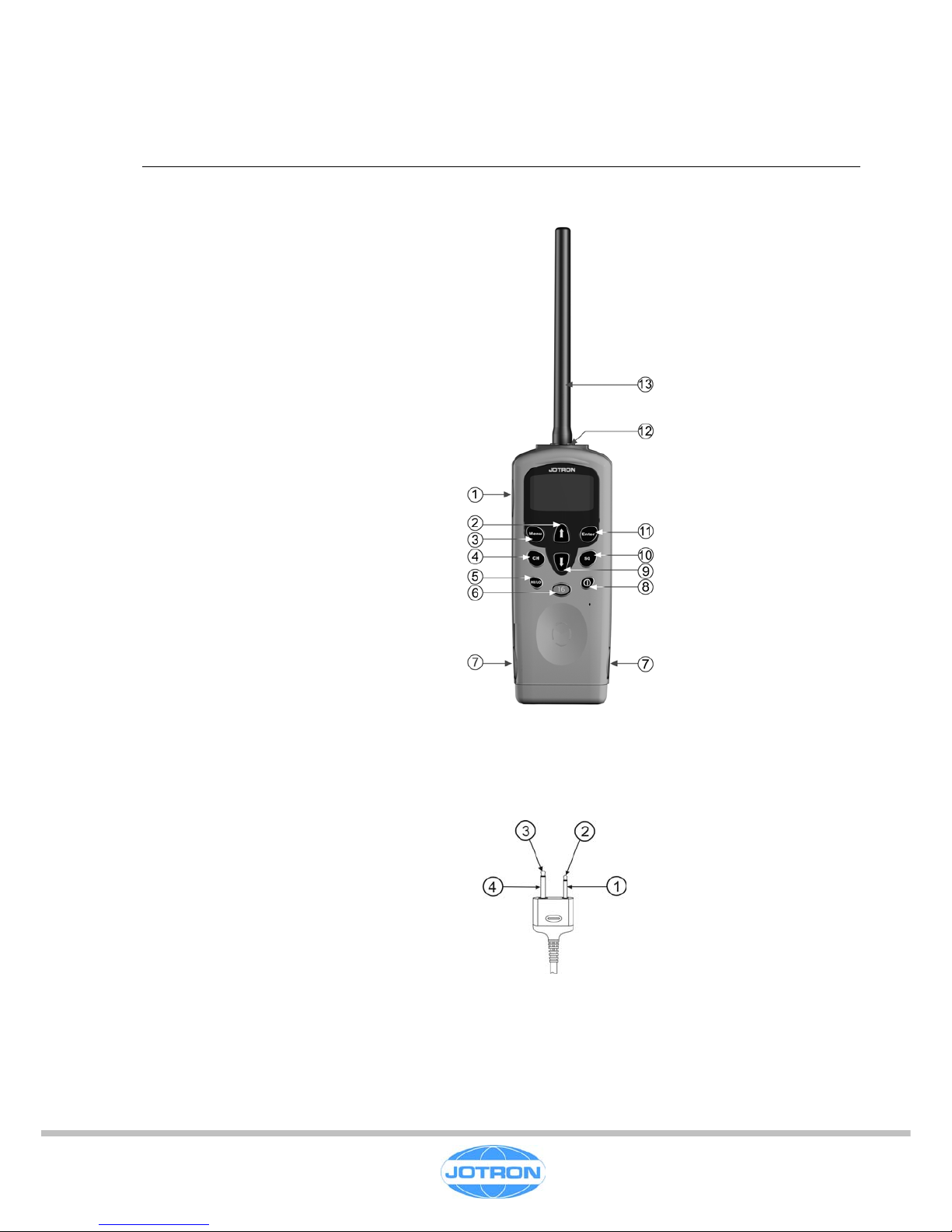
Controls
Fig. 2.1 shows the location of different
controls and facilities of the Tron TR20:
1 - PTT (Push To Talk)
2 - Up
3 - Menu
4 - Channel
5 - High / Low power
6 - Channel 16
7 - Battery release
8 - ON / OFF
9 - Down
10 - Squelch
11 - Enter DW/TW
12 - Auxiliary connector
(Tron TR20 Plus only)
13 - Antenna
Auxiliary connector
The auxiliary connector on the Tron TR20 Plus enables the user to connect an external
microphone or headset.
1- Mic ground
2- Mic
3- Speaker
4- Speaker ground
For further instructions on use, please consult the Users Manual.
Tron TR20
4-1

5. TECHNICAL DESCRIPTION
Introduction
The transceiver consists of 3 printed circuit boards.
• Main board (99940)
This board contains the power supply and power control circuits. In addition the board contains the
microcontroller and display.
• Synth/IF board (99936a)
The synthesiser unit includes the VCO, buffer amplifier and synthesiser for the transceiver. It also
contains the IF and detector circuits for the receiver.
• RF board (99936b).
This board contains the transmitter power amplifier chain, RF switch, the RF front end and first
mixer.
Most components used are of surface mount type except some high-power devices.
Main board (99940)
The Main board can be divided into three main sections:
• Audio frequency section.
• Power supply section.
• Control circuits.
Audio Frequency section
Microphone amplifier, bandpass filter and modulation adjustment
The microphone is connected via the switch (101) to the VOGAD (Voice-Operated Gain-Adjusting
Device) amplifier (IC103).
The gain of this amplifier is automatically adjusted and different acoustic levels will be corrected to
give nominal modulation.
When an external microphone is connected, IC101 is used to turn of the internal microphone.
This function is performed by IC104A. It is sensing the presence of an external microphone by sensing
the current flowing through the external microphone supply.
The next amplifier stage is operates as gain stage and limiter (IC102A). To prevent the deviation
passing ±5kHz, the limiter is clipping signals with a peak level of more than +
2.5V.
C109 and R108/R110 perform the pre-emphasis of the modulation signal.
The signal then enters the band pass filter (IC102B).
Output from the band pass is fed to IC108. IC108 is a quad D/A converter. The modulation signal is
scaled by the D/A converter to give the correct modulation. The microcontroller controls the D/A
converter. The signal is then fed to the modulator on the VCO.
Tron TR20
5-1

Receiver Audio circuits
The audio signal from the IF section enters through J103 # 19, and is feed to the de-emphasis network
(R128, C122), and then to the low pass filter (IC105B). The signal is then feed to the audio output
amplifier (IC107). The microcontroller adjusts the volume by varying the voltage on pin 4 with the D/A
converter (IC108).
The squelch level is also adjusted with the D/A converter. The level set by the microcontroller is
compared with the RSSI signal from the demodulator by IC104B. R135 provides hysteresis to the
circuit.
Control Circuits
The microcontroller (IC109) sets up the synthesiser and controls all functions in the transceiver.
It has a built in ADC with multiplexer which is used to measure the most important parameters in the
transceiver. During transmitt the output power is measured to check that the transmitter is actually
transmitting, and the lock status of the synthesiser is also checked. Any fault will be indicated on the
display. (E1 = Synthesiser out of lock, E2 = No output power).
Configuration data, such as channel settings, volume and squelch settings are stored in an external
EEPROM (IC111). Both the graphical display and the synthesiser are controlled via the SPI bus.
Q110 and D106 act as an infrared port used for factory testing.
The microcontroller contains one software module. To read out the software version, enter the main
menu and select ”info”. The software version is then shown on the display. The controller is made with
flash technology, so firmware upgrade is possible without changing the controller. J104 is the
programming port.
Power supply Circuits
IC113 is the main power switch in the radio. Power off is controlled from the microcontroller.
IC112 is a low drop voltage regulator, and supplies 5V to most of the radio’s circuits.
Synth / IF board (99936a).
Synthesiser
The synthesiser is located on the Synth/IF board. M1 is the oscillator transistor in the VCO. The
oscillator frequency is controlled by the varicaps D2 - D6.
The signal is tapped on the lower side of the tank coil to ensure as high Q as possible. The signal is
buffered by the emitter follower Q4, and then feed to the synthesiser (IC2). The synthesiser has a built
in dual modulus prescaler. The microcontroller controls the synthesiser via the SPI bus.
The output from the phase comparator (#2) is filtered in a passive loop filter to minimise noise in the
output signal.
The modulation signal is applied to D11.
Q6 and surrounding components act as a low noise voltage regulator, filtering the supply voltage for
the VCO.
The output signal is feed to the first mixer on the RF board.
Tron TR20
5-2

IF circuit
The 21.4 MHz signal from the 1. Mixer on the RF board is feed trough two sections of crystal filters
(Y1 and Y2).
The signal is then fed trough a matching network into the IF integrated circuit (IC1). It then enters the
second mixer, and is converted down to 450kHz, amplified and feed trough two sections of ceramic
band pass filters (FLT1 and FLT2). Then it passes through a limiter circuit and is fed to the
discriminator DXR1. This produces demodulated audio on #9, which is fed to the band pass filter on
the main board.
The second Local Oscillator, which is a part of the IF circuit, operates at 20.950MHz and also
functions as the reference for the synthesiser controlling the 1 LO. The oscillator is voltage
controllable, to make frequency adjustment and temperature compensation available for the
microcontroller. Frequency adjustment is available from the front panel of the transceiver.
RF board (99936b).
Receiver front end
The antenna signal enters first the low pass filter, and the first band pass filter. The signal is then
amplified by Q1, before entering the second band pass filter. It then enters the first mixer (Q2) were it
is mixed with the LO signal from the synthesiser down to 21.4 MHz. The signal is the feed to the
Synth/IF board through J1 #11.
Transmitter section
The LO signal is amplified by Q8 and feed to the mixer in Rx mode, and to the transmitter in Tx mode.
IC3 is an integrated output stage with up to 5W output power. The power output is adjusted with the
bias pin (#2), and is controlled by the “SET_PWR” signal from the micro controller. IC5 acts as a
buffer amplifier.
The output power is detected by D18, and the produced voltage is feed to one of the A/D inputs on the
microcontroller to check that the transmitter is actually transmitting.
The output from IC3 is taken through the RF switch (D9,D10), trough the low pass filter to the antenna.
Tron TR20
5-3

6. MAINTENANCE
No maintenance is necessary except to check / tune the LO frequency after 1 year and then every 3rd
year.
Tuning of LO frequency
The LO frequency is checked at the antenna output. Unscrew the antenna and connect the output to a
frequency counter or a radio testset. Note that the input impedance should be 50Ω, and the input must
be able to handle up to 5W of RF power. The connector is standard SMA.
1. Press the “Hi/Lo” key while powering up the Tron TR20 to enable service mode.
2. Set the radio to Low Power by pressing the “Hi/Lo” key.
3. Enter the main menu, and use the arrow keys to select “Ref” adjustment.
4. Press “PTT” and read the frequency on the frequency counter. The limit is +1.5kHz.
5. If adjustment is required, use the arrow keys to adjust the centre frequency.
6. Press enter to store the setting.
When refitting the antenna, apply a small amount of silicon grease on the mating surface oft the
antenna. Tighten with hand force only, make sure that the rubber housing on the antenna mates well
with the rubber sealing on the housing.
Other adjustments
The service mode enables access to a few more adjustments.
These are: Power output (High and Low) and modulation.
Note! These adjustments are meant for factory use only.
To adjust High Power:
1- Press the “Hi/Lo” key while powering up the Tron TR20 to enable service mode.
2- Set the radio to High Power by pressing the “Hi/Lo” key.
3- Enter the main menu, and use the arrow keys to select “Pwr” adjustment.
4- Press “PTT” and read the output power on a power meter. The output power should be
approx. 2W on Tron TR20 GMDSS and 4W – 5W on Tron TR20 PLUS.
5- If adjustment is required, use the arrow keys to adjust the output power.
6- Press enter to store the setting.
To adjust Low Power:
1- Press the “Hi/Lo” key while powering up the Tron TR20 to enable service mode.
2- Set the radio to Low Power by pressing the “Hi/Lo” key.
3- Enter the main menu, and use the arrow keys to select “Pwr” adjustment.
4- Press “PTT” and read the output power on a power meter. The output power should be
approx. 1W on Tron TR20 GMDSS and Tron TR20 PLUS.
5- If adjustment is required, use the arrow keys to adjust the output power.
6- Press enter to store the setting.
NOTE! On Tron TR20 GMDSS the power output must never be adjusted higher than 2.5W.
If a higher output power is selected, the radio may not operate properly due to the relative high internal
resistance of the Lithium battery.
Tron TR20
6-1

To adjust Modulation:
The radio must be connected to a radio test set, and an audio signal must be applied to the
microphone input (Tron TR20 PLUS).
1- Press the “Hi/Lo” key while powering up the Tron TR20 to enable service mode.
2- Set the radio to High Power by pressing the “Hi/Lo” key.
3- Enter the main menu, and use the arrow keys to select “Mod” adjustment.
4- Press “PTT” and read the modulation on a modulation meter.
5- If adjustment is required, use the arrow keys to adjust the modulation.
6- Press enter to store the setting.
Tron TR20
6-2

7. DIAGRAMS
Block diagram Tron TR20 E-80020
Circuit diagram, Main board part 1 E-99940 -1/2
Circuit diagram, Main board part 2 E-99940 -2/2
Place plan, Main board, part 1 KP-99940 -1/2
Place plan, Main board, part 2 KP-99940 -2/2
Circuit diagram, RF board E-99936-1/2
Circuit diagram, Synth / IF board E-99936-2/2
Place plan, Synth / IF board & RF board, part 1 KP-99936-1/2
Place plan, Synth / IF board & RF board, part 2 KP-99936-2/2
Circuit diagram, Lithium Battery E-80060
Circuit diagram, NiMH Battery E-80059
NOTE! The place plan drawings show the maximum configuration for a printed circuit board. For
components actually fitted on a printed circuit board, please refer to the parts list for that board.
Tron TR20
7-1


09.01.2003 12:53:13 f=0.99 M:/Products/TR20/Technical_Info/Drawing_Electrical/TR20/Mainboard/0215/99879mod.sch (Sheet: 1/2)

09.01.2003 12:53:48 f=0.99 M:/Products/TR20/Technical_Info/Drawing_Electrical/TR20/Mainboard/0215/99879mod.sch (Sheet: 2/2)

09.01.2003 11:03:32 f=1.41 M:/Products/TR20/Technical_Info/Drawing_Electrical/TR20/Mainboard/0215/99879mod.brd

09.01.2003 11:04:23 f=1.41 mirrored M:/Products/TR20/Technical_Info/Drawing_Electrical/TR20/Mainboard/0215/99879mod.brd


09.01.2003 11:07:22 f=1.41 M:/Products/TR20/Technical_Info/Drawing_Electrical/TR20/RF_board/R0230/99936_r0.brd

09.01.2003 11:07:57 f=1.41 mirrored M:/Products/TR20/Technical_Info/Drawing_Electrical/TR20/RF_board/R0230/99936_r0.brd


8. PARTS LISTS
• Part list, Complete Transceiver BOM-99930
• Part list, Main Board BOM-99940
• Part list, RF Unit BOM-99936
• Part list, Lithium Battery BOM-80060
• Part list, NiMH Battery BOM-80059
Tron TR20
8-1

Bill Of Material
Item
Version
Date
6.11.2001
99930 Tron TR20 PORTABLE GMDSS RADIO Manufacturing
JOTRON electronics a.s.
Item Name / Description Makes no. / Additional name Sub pos.
80030 Complete front (GMDSS)
1
99944 Brytertapp for PTT
A
BS 10
99893 Pakningstiver
Delrin 507 10
99906 Screw 2,5x10
PT-Screw KB25 x 10 WW 1451 11
99877 BATTERISNEPP
TRON VHF MkII 12
99936 RF board complete
Front end + synth.board 13
99928 Batterikontaktpinne
14
80020 El.unit complete (GMDSS)
3
99880
A
NTENNA for Tron TR-20
4
99926
A
ntennekontakt
5
99912 Tetningshette v/headset conn.
5
99871 BAKDEKSEL
Lexan 503R Orange (6312 12,75) 6
99876 HOVEDPAKNING/RADIO
TRON VHF MkII 7
99874 BELTEKLIPS
Delrin 500 Sort 8
99932 O-ring
Simrit 72 NBR 872 (Ø3,1 x 1,0x5,0) 9

Bill Of Material
Item
Version
Page 1 of 5
Date
6.11.2001
99940 Mainboard complete Design
EM3727
JOTRON electronics a.s.
Item Name / Description Makes no. / Additional name Sub pos.
98284 CHIP CAP 100p 50V - 0603
MURATA GRM39 COG 101J 50
C101
99796 CHIP CAP 1uF 16v X7R 0805
MURATA GRM40 X7R 105M 16
C102
99796 CHIP CAP 1uF 16v X7R 0805
MURATA GRM40 X7R 105M 16
C103
99796 CHIP CAP 1uF 16v X7R 0805
MURATA GRM40 X7R 105M 16
C104
98322 CHIP CAP 100n 25V - 0603
MURATA GRM39 X7R 104Z 25
C105
98322 CHIP CAP 100n 25V - 0603
MURATA GRM39 X7R 104Z 25
C106
98322 CHIP CAP 100n 25V - 0603
MURATA GRM39 X7R 104Z 25
C107
98322 CHIP CAP 100n 25V - 0603
MURATA GRM39 X7R 104Z 25
C108
98329 CHIP CAP 220n 16V - 0603 (Y5V)
MURATA GRM39Y5V224Z16
C109
98329 CHIP CAP 220n 16V - 0603 (Y5V)
MURATA GRM39Y5V224Z16
C110
98291 CHIP CAP 470p 50V - 0603 (COG)
MURATA GRM39 COG 471J 50S
C111
98308 CHIP CAP 5n6 50v - 0603
MURATA GRM39 X7R 562K 50
C112
98294 CHIP CAP 820p 25V - 0603 (COH)
MURATA GRM39 COH 821J 25S
C113
98311 CHIP CAP 15n 50V - 0603
MURATA GRM39 X7R 153K 50
C114
99657 1210 - 22 uF/10 V Ceramic capacitor
MURATA GRM235Y5V226Z10
C115
98291 CHIP CAP 470p 50V - 0603 (COG)
MURATA GRM39 COG 471J 50S
C116
97357 CHIP TANTAL 3u3 16V LTA-B
ELNA SK-1C 335 M-RB
C117
98310 CHIP CAP 10n 50V - 0603 (X7R)
MURATA GRM39 X7R 103K 50
C118
98322 CHIP CAP 100n 25V - 0603
MURATA GRM39 X7R 104Z 25
C120
98322 CHIP CAP 100n 25V - 0603
MURATA GRM39 X7R 104Z 25
C121
98312 CHIP CAP 22n 25V - 0603
MURATA GRM39 X7R 223K 25
C122
93225 CHIP CAP 100nF 50V X7R 10% - 0805
MURATA GRM40 X7R 104 K50
C123
98290 CHIP CAP 390p 50V - 0603
MURATA GRM39 COG 391J 50S
C124
98294 CHIP CAP 820p 25V - 0603 (COH)
MURATA GRM39 COH 821J 25S
C125
98317 CHIP CAP 22n 50V - 0603
MURATA GRM39 Y5V 223Z 50
C126
98295 CHIP CAP 470n 16V - 0603 (Y5V)
MURATA GRM39 Y5V 474Z 16PT
C128
99796 CHIP CAP 1uF 16v X7R 0805
MURATA GRM40 X7R 105M 16
C129
99796 CHIP CAP 1uF 16v X7R 0805
MURATA GRM40 X7R 105M 16
C130
98319 CHIP CAP 47n 50V - 0603
MURATA GRM39 Y5V 473Z 50
C131
80012 Chip El.lytt 100u/6.3v F46
NIPPON CHEMI-CON MVS6.3VC100M F46 TP
C132
95718 CHIP CAP 470nF 16V
MURATA GRM40 Y5V 474Z 16
C133
98284 CHIP CAP 100p 50V - 0603
MURATA GRM39 COG 101J 50
C134
98284 CHIP CAP 100p 50V - 0603
MURATA GRM39 COG 101J 50
C135
80041 Chip Cap. Array, 4x100p/1206, GNM30-401
MURATA GNM30-401COG101K050
C136
OMIT Utgår
C137
OMIT Utgår
C139
92365 CHIP CAP 2u2 16V Y5V
MURATA GRM42-6 Y5V 225 Z16
C140
OMIT Utgår
C141
98329 CHIP CAP 220n 16V - 0603 (Y5V)
MURATA GRM39Y5V224Z16
C142
92365 CHIP CAP 2u2 16V Y5V
MURATA GRM42-6 Y5V 225 Z16
C144
OMIT Utgår
C145
OMIT Utgår
C146
OMIT Utgår
C147
98322 CHIP CAP 100n 25V - 0603
MURATA GRM39 X7R 104Z 25
C148
80042 EMI FILTER 1u0 CHIP 0805
MURATA NFM2012P13C105FT1M00
C149

Bill Of Material
Item
Version
Page 2 of 5
Date
6.11.2001
99940 Mainboard complete Design
EM3727
JOTRON electronics a.s.
Item Name / Description Makes no. / Additional name Sub pos.
99796 CHIP CAP 1uF 16v X7R 0805
MURATA GRM40 X7R 105M 16
C150
80012 Chip El.lytt 100u/6.3v F46
NIPPON CHEMI-CON MVS6.3VC100M F46 TP
C151
95718 CHIP CAP 470nF 16V
MURATA GRM40 Y5V 474Z 16
C152
98329 CHIP CAP 220n 16V - 0603 (Y5V)
MURATA GRM39Y5V224Z16
C153
98329 CHIP CAP 220n 16V - 0603 (Y5V)
MURATA GRM39Y5V224Z16
C154
98329 CHIP CAP 220n 16V - 0603 (Y5V)
MURATA GRM39Y5V224Z16
C155
98329 CHIP CAP 220n 16V - 0603 (Y5V)
MURATA GRM39Y5V224Z16
C156
98322 CHIP CAP 100n 25V - 0603
MURATA GRM39 X7R 104Z 25
C157
98322 CHIP CAP 100n 25V - 0603
MURATA GRM39 X7R 104Z 25
C158
98322 CHIP CAP 100n 25V - 0603
MURATA GRM39 X7R 104Z 25
C159
98322 CHIP CAP 100n 25V - 0603
MURATA GRM39 X7R 104Z 25
C160
99657 1210 - 22 uF/10 V Ceramic capacitor
MURATA GRM235Y5V226Z10
C161
99797 EL..CAP 220uF,6.3V, low ESR, 5mm high
Sanyo UAX 220uF/6.3V
C162
99797 EL..CAP 220uF,6.3V, low ESR, 5mm high
Sanyo UAX 220uF/6.3V
C163
98284 CHIP CAP 100p 50V - 0603
MURATA GRM39 COG 101J 50
C164
98284 CHIP CAP 100p 50V - 0603
MURATA GRM39 COG 101J 50
C165
98300 CHIP CAP 1n 50V - 0603
MURATA GRM39 X7R 102K 50
C166
99292 CHIP CAP 1u 10V - 0603 (Y5V)
MURATA GRM39Y5V105Z10
C169
80029 LED, Green, SMD, 0603
Infineon Technologies AG LGQ971- Q62702-P5189
D101
80029 LED, Green, SMD, 0603
Infineon Technologies AG LGQ971- Q62702-P5189
D102
94432 DIODE BAW 56 SOT-23
PHILIPS BAW56,215
D103
80029 LED, Green, SMD, 0603
Infineon Technologies AG LGQ971- Q62702-P5189
D104
80029 LED, Green, SMD, 0603
Infineon Technologies AG LGQ971- Q62702-P5189
D105
80019 LED, IR, 950nm, Topled, SMD, P-LCC-2
SIEMENS Q62702-P1690
D106
94435 DIODE BAT 17 SOT-23
PHILIPS BAT17,215
D107
94435 DIODE BAT 17 SOT-23
PHILIPS BAT17,215
D108
93099 DUAL DIODE BAV70
PHILIPS BAV70,215
D109
93101 SINGLE GATE L-MOS SWITCH
TOSHIBA TC4S66F
IC101
80033 Op.Amp, Dual, L-volt, RR-o, LMV358,MSOP8
National LMV358MM
IC102
94763 Microphone Preamplifier SSM2166
A
nalog Devices SSM2166S (S0-14)
IC103
80033 Op.Amp, Dual, L-volt, RR-o, LMV358,MSOP8
National LMV358MM
IC104
80033 Op.Amp, Dual, L-volt, RR-o, LMV358,MSOP8
National LMV358MM
IC105
80033 Op.Amp, Dual, L-volt, RR-o, LMV358,MSOP8
National LMV358MM
IC106
80034
A
mp, Audio, 750mW w/hp, LM4865, MSOP8
National LM4865MM
IC107
80036 D/A, 8-bit, 4-ch, SPI, TLC5620, SO-14
Texas TLC5620ID
IC108
80043 Microcontroller, ATmega163L, SMD,TQFP-44
A
tmel ATmega163L-4AI
IC109
80037 Volt.Sup., 3.3V, 200ms, TPS3809, SOT-23
Texas TPS3809K33DBVT
IC110
99073
A
T25080, 1024x8 SPI EEPROM, SMD
A
tmel AT25080N-10SI
IC111
80038 Volt.reg, 5v, 250mA/0.4v, L4931, D-pak
SGS L4931CDT50
IC112
99762 SI2307, P-MFET,30V, 80mOhm@10V, SOT-23
Siliconix SI2307DS
IC113
OMIT Utgår
J101
OMIT Utgår
J102
80026 Socket, 1x22, 1.27mm, SMD
Samtec RSM-122-02-L-S-K
J103
80024 Socket, Low profile, 2x3, 1.27mm, SMD
Samtec CLP-103-02-F-D
J104
93158 DROSSEL 1.0uH SMD - 1210
SIEMENS B82422-A1102-K100
L101

Bill Of Material
Item
Version
Page 3 of 5
Date
6.11.2001
99940 Mainboard complete Design
EM3727
JOTRON electronics a.s.
Item Name / Description Makes no. / Additional name Sub pos.
97411 DROSSEL SMD 150nH
SIEMENS B82422-A3151-K100
L102
93158 DROSSEL 1.0uH SMD - 1210
SIEMENS B82422-A1102-K100
L103
93158 DROSSEL 1.0uH SMD - 1210
SIEMENS B82422-A1102-K100
L104
99899 DISPLAY - LCD SEK1054
SEIKO SEK1054B-7a
LCD101
80023 Loudspeaker, Myl, 36x4.8 mm , 8R, 1/2 w
Veco, Vansonic Enterprise Co 36S08FNM50B
LS101
80022 Microphone, 8x5mm ,omni-dir, elect
Veco, Vansonic Enterprise Co VM-54LP
MIC000
99879 PCB HOVEDKORT
TRON VHF MkII PCB
94443 TRANSISTOR BC 817 SOT-23
PHILIPS BC817,215
Q101
94443 TRANSISTOR BC 817 SOT-23
PHILIPS BC817,215
Q102
94443 TRANSISTOR BC 817 SOT-23
PHILIPS BC817,215
Q103
94443 TRANSISTOR BC 817 SOT-23
PHILIPS BC817,215
Q104
97677 MOSFET
PHILIPS BSS84
Q105
97677 MOSFET
PHILIPS BSS84
Q106
97677 MOSFET
PHILIPS BSS84
Q107
94443 TRANSISTOR BC 817 SOT-23
PHILIPS BC817,215
Q108
94444 TRANSISTOR BC 807 SOT-23
PHILIPS BC807,215
Q109
80021 Photo Transistor, NPN, Topled, SMD
SIEMENS Q62702-P1607
Q110
94443 TRANSISTOR BC 817 SOT-23
PHILIPS BC817,215
Q111
96984 TRANSISTOR MOSFET BST 82
PHILIPS BST82,215
Q112
OMIT Utgår
R101
98399 CR 0603 100R 1%
ROHM MCR03 EZP FX-1000
R102
98411 CR 0603 330R 1%
ROHM MCR03 EZP FX-3300
R103
98465 CR 0603 56k 1%
ROHM MCR03 EZP FX-5602
R104
98435 CR 0603 3k3 1%
ROHM MCR03 EZP FX-3301
R105
98455 CR 0603 22k 1%
ROHM MCR03 EZP FX-2202
R106
OMIT Utgår
R107
98451 CR 0603 15k 1%
ROHM MCR03 EZP FX-1502
R108
99294
A
RC241 4x0603 resistor array 10k (1206
)
PHILIPS 2350 034 10103
R109
98430 CR 0603 2k0 1%
ROHM MCR03 EZP FX-2001
R110
98470 CR 0603 100k 1%
ROHM MCR03 EZP FX-1003
R111
98431 CR 0603 2k2 1%
ROHM MCR03 EZP FX-2201
R112
98439 CR 0603 4K7 1%
ROHM MCR03 EZP FX-4701
R113
98470 CR 0603 100k 1%
ROHM MCR03 EZP FX-1003
R114
98431 CR 0603 2k2 1%
ROHM MCR03 EZP FX-2201
R115
98703 CR 0603 0R 1%
ROHM 0603 jump
R116
98455 CR 0603 22k 1%
ROHM MCR03 EZP FX-2202
R117
98492 CR 0603 910k 1%
ROHM MCR03 EZP FX-9103
R118
98463 CR 0603 47k 1%
ROHM MCR03 EZP FX-4702
R119
98423 CR 0603 1k0 1%
ROHM MCR03 EZP FX-1001
R120
98431 CR 0603 2k2 1%
ROHM MCR03 EZP FX-2201
R121
98431 CR 0603 2k2 1%
ROHM MCR03 EZP FX-2201
R122
98457 CR 0603 27k 1%
ROHM MCR03 EZP FX-2702
R123
98506 CR 0603 10M 5%
ROHM MCR03 EZH J-1005
R124
98470 CR 0603 100k 1%
ROHM MCR03 EZP FX-1003
R125
99294
A
RC241 4x0603 resistor array 10k (1206
)
PHILIPS 2350 034 10103
R126

Bill Of Material
Item
Version
Page 4 of 5
Date
6.11.2001
99940 Mainboard complete Design
EM3727
JOTRON electronics a.s.
Item Name / Description Makes no. / Additional name Sub pos.
98447 CR 0603 10k 1%
ROHM MCR03 EZP FX-1002
R127
99295
A
RC241 4x0603 resistor array 68k (1206
)
PHILIPS 2350 034 10683
R128
98423 CR 0603 1k0 1%
ROHM MCR03 EZP FX-1001
R129
OMIT Utgår
R130
98455 CR 0603 22k 1%
ROHM MCR03 EZP FX-2202
R131
98470 CR 0603 100k 1%
ROHM MCR03 EZP FX-1003
R132
98447 CR 0603 10k 1%
ROHM MCR03 EZP FX-1002
R133
98470 CR 0603 100k 1%
ROHM MCR03 EZP FX-1003
R134
98506 CR 0603 10M 5%
ROHM MCR03 EZH J-1005
R135
98470 CR 0603 100k 1%
ROHM MCR03 EZP FX-1003
R136
98447 CR 0603 10k 1%
ROHM MCR03 EZP FX-1002
R137
98447 CR 0603 10k 1%
ROHM MCR03 EZP FX-1002
R138
98470 CR 0603 100k 1%
ROHM MCR03 EZP FX-1003
R139
98435 CR 0603 3k3 1%
ROHM MCR03 EZP FX-3301
R140
98470 CR 0603 100k 1%
ROHM MCR03 EZP FX-1003
R141
98403 CR 0603 150R 1%
ROHM MCR03 EZP FX-1500
R142
98423 CR 0603 1k0 1%
ROHM MCR03 EZP FX-1001
R143
80013
A
RC241 4x0603 resistor array 470R (1206
)
PHILIPS 2350 034 10471
R144
98407 CR 0603 200R 1%
ROHM MCR03 EZP FX-2000
R145
98407 CR 0603 200R 1%
ROHM MCR03 EZP FX-2000
R146
98407 CR 0603 200R 1%
ROHM MCR03 EZP FX-2000
R147
80014
A
RC241 4x0603 resistor array 100k (1206
)
PHILIPS 2350 034 10104
R148
80013
A
RC241 4x0603 resistor array 470R (1206
)
PHILIPS 2350 034 10471
R149
98407 CR 0603 200R 1%
ROHM MCR03 EZP FX-2000
R150
98393 CR 0603 56R 5%
ROHM MCR03 EZH J-56R
R151
OMIT Utgår
R152
OMIT Utgår
R153
OMIT Utgår
R154
98447 CR 0603 10k 1%
ROHM MCR03 EZP FX-1002
R156
99294
A
RC241 4x0603 resistor array 10k (1206
)
PHILIPS 2350 034 10103
R157
98478 CR 0603 220k 1%
ROHM MCR03 EZP FX-2203
R159
98478 CR 0603 220k 1%
ROHM MCR03 EZP FX-2203
R160
80015 Chip Resistor, NTC, 220k, 0805
Epcos B57620-C224-K62
R161
98496 CR 0603 1M8 5%
ROHM MCR03 EZH J-1804
R162
98480 CR 0603 270k 1%
ROHM MCR03 EZP FX-2703
R163
98375 CR 0603 10R 5%
ROHM MCR03 EZH J-10R
R164
98470 CR 0603 100k 1%
ROHM MCR03 EZP FX-1003
R165
98470 CR 0603 100k 1%
ROHM MCR03 EZP FX-1003
R166
98463 CR 0603 47k 1%
ROHM MCR03 EZP FX-4702
R167
OMIT Utgår
R168
98447 CR 0603 10k 1%
ROHM MCR03 EZP FX-1002
R169
98447 CR 0603 10k 1%
ROHM MCR03 EZP FX-1002
R170
98470 CR 0603 100k 1%
ROHM MCR03 EZP FX-1003
R171
98375 CR 0603 10R 5%
ROHM MCR03 EZH J-10R
R172
98459 CR 0603 33k 1%
ROHM MCR03 EZP FX-3302
R173

Bill Of Material
Item
Version
Page 5 of 5
Date
6.11.2001
99940 Mainboard complete Design
EM3727
JOTRON electronics a.s.
Item Name / Description Makes no. / Additional name Sub pos.
98423 CR 0603 1k0 1%
ROHM MCR03 EZP FX-1001
R174
98399 CR 0603 100R 1%
ROHM MCR03 EZP FX-1000
R175
98399 CR 0603 100R 1%
ROHM MCR03 EZP FX-1000
R176
98399 CR 0603 100R 1%
ROHM MCR03 EZP FX-1000
R177
98431 CR 0603 2k2 1%
ROHM MCR03 EZP FX-2201
R178
80017 Switch, Side-act.TACT,h=2.3mm, Large
Huajie TSCB-3
SW101
80016 Switch, TACT, 6x6mm, 2.3N
A
LPS SKHMPU
SW102
80016 Switch, TACT, 6x6mm, 2.3N
A
LPS SKHMPU
SW103
80016 Switch, TACT, 6x6mm, 2.3N
A
LPS SKHMPU
SW104
80016 Switch, TACT, 6x6mm, 2.3N
A
LPS SKHMPU
SW105
80016 Switch, TACT, 6x6mm, 2.3N
A
LPS SKHMPU
SW106
80016 Switch, TACT, 6x6mm, 2.3N
A
LPS SKHMPU
SW107
80016 Switch, TACT, 6x6mm, 2.3N
A
LPS SKHMPU
SW108
80016 Switch, TACT, 6x6mm, 2.3N
A
LPS SKHMPU
SW109
80016 Switch, TACT, 6x6mm, 2.3N
A
LPS SKHMPU
SW110
80066 3.6864 MHz Ceramic resonator
MURATA CSTCC 3.6864MHZ MG-TC
X101
Revision date
Revision Requested by Reference
16.11.2001 EM3727
A
.F. R107,C169,R178,R152-3-4,R123,R121
03.10.2001 EM3666 FIT

Bill Of Material
Item
Version
Page 1 of 5
Date
6.11.2001
99936 RF board complete Design
EM3728
JOTRON electronics a.s.
Item Name / Description Makes no. / Additional name Sub pos.
98277 CHIP CAP 18p 50V - 0603
MURATA GRM39 COG 180J 50
C001
98259 CHIP CAP 39p 50V - 0603
MURATA GRM39 COG 390J 50
C002
98282 CHIP CAP 56p 50V - 0603
MURATA GRM39 COG 560J 50
C003
98280 CHIP CAP 33p 50V - 0603
MURATA GRM39 COG 330J 50
C004
OMIT Utgår
C005
98300 CHIP CAP 1n 50V - 0603
MURATA GRM39 X7R 102K 50
C006
98274 CHIP CAP 10p 50V - 0603
MURATA GRM39 COG 100D 50
C007
97656 INDUCTOR 10 nH
TAIYO YUDEN HK2125 10nH
C008
98280 CHIP CAP 33p 50V - 0603
MURATA GRM39 COG 330J 50
C009
98515 CHIP CAP 4p7 50V - 0603
MURATA GRM39 4R7C 50
C010
98281 CHIP CAP 47p 50V - 0603
MURATA GRM39 COG 470J 50
C011
98287 CHIP CAP 180p 50V - 0603
MURATA GRM39 COG 181J 50
C012
98281 CHIP CAP 47p 50V - 0603
MURATA GRM39 COG 470J 50
C013
98518 CHIP CAP 8p2 50V - 0603
MURATA GRM39 COG 8R2D 50
C014
OMIT Utgår
C015
98284 CHIP CAP 100p 50V - 0603
MURATA GRM39 COG 101J 50
C016
98284 CHIP CAP 100p 50V - 0603
MURATA GRM39 COG 101J 50
C017
98281 CHIP CAP 47p 50V - 0603
MURATA GRM39 COG 470J 50
C018
98275 CHIP CAP 12p 50V - 0603
MURATA GRM39 COG 120J 50
C019
98518 CHIP CAP 8p2 50V - 0603
MURATA GRM39 COG 8R2D 50
C020
OMIT Utgår
C021
98279 CHIP CAP 27p 50V - 0603
MURATA GRM39 COG 270J 50
C022
98322 CHIP CAP 100n 25V - 0603
MURATA GRM39 X7R 104Z 25
C023
98281 CHIP CAP 47p 50V - 0603
MURATA GRM39 COG 470J 50
C024
OMIT Utgår
C025
98300 CHIP CAP 1n 50V - 0603
MURATA GRM39 X7R 102K 50
C026
99396 CHIP CAP 82p 50V - 0603
MURATA GRM39 COG 820J 50
C027
98322 CHIP CAP 100n 25V - 0603
MURATA GRM39 X7R 104Z 25
C028
98312 CHIP CAP 22n 25V - 0603
MURATA GRM39 X7R 223K 25
C029
98312 CHIP CAP 22n 25V - 0603
MURATA GRM39 X7R 223K 25
C030
98284 CHIP CAP 100p 50V - 0603
MURATA GRM39 COG 101J 50
C031
98310 CHIP CAP 10n 50V - 0603 (X7R)
MURATA GRM39 X7R 103K 50
C032
98312 CHIP CAP 22n 25V - 0603
MURATA GRM39 X7R 223K 25
C033
98312 CHIP CAP 22n 25V - 0603
MURATA GRM39 X7R 223K 25
C034
98322 CHIP CAP 100n 25V - 0603
MURATA GRM39 X7R 104Z 25
C035
98322 CHIP CAP 100n 25V - 0603
MURATA GRM39 X7R 104Z 25
C036
98278 CHIP CAP 22p 50V - 0603
MURATA GRM39 COG 220J 50
C037
OMIT Utgår
C038
98300 CHIP CAP 1n 50V - 0603
MURATA GRM39 X7R 102K 50
C039
98322 CHIP CAP 100n 25V - 0603
MURATA GRM39 X7R 104Z 25
C040
98300 CHIP CAP 1n 50V - 0603
MURATA GRM39 X7R 102K 50
C041
98284 CHIP CAP 100p 50V - 0603
MURATA GRM39 COG 101J 50
C042
98310 CHIP CAP 10n 50V - 0603 (X7R)
MURATA GRM39 X7R 103K 50
C043
95033 CHIP TANTAL 1uF-B 35V
ELNA SK-1V 105 M-RB
C044
98322 CHIP CAP 100n 25V - 0603
MURATA GRM39 X7R 104Z 25
C045

Bill Of Material
Item
Version
Page 2 of 5
Date
6.11.2001
99936 RF board complete Design
EM3728
JOTRON electronics a.s.
Item Name / Description Makes no. / Additional name Sub pos.
98322 CHIP CAP 100n 25V - 0603
MURATA GRM39 X7R 104Z 25
C046
98322 CHIP CAP 100n 25V - 0603
MURATA GRM39 X7R 104Z 25
C047
98322 CHIP CAP 100n 25V - 0603
MURATA GRM39 X7R 104Z 25
C048
98284 CHIP CAP 100p 50V - 0603
MURATA GRM39 COG 101J 50
C049
98288 CHIP CAP 220p 50V - 0603
MURATA GRM39 COG 221J 50
C050
98300 CHIP CAP 1n 50V - 0603
MURATA GRM39 X7R 102K 50
C051
98322 CHIP CAP 100n 25V - 0603
MURATA GRM39 X7R 104Z 25
C052
98322 CHIP CAP 100n 25V - 0603
MURATA GRM39 X7R 104Z 25
C053
98322 CHIP CAP 100n 25V - 0603
MURATA GRM39 X7R 104Z 25
C054
98511 CHIP CAP 2p2 50V - 0603
MURATA GRM39 COG 2R2C 50
C055
98259 CHIP CAP 39p 50V - 0603
MURATA GRM39 COG 390J 50
C056
98322 CHIP CAP 100n 25V - 0603
MURATA GRM39 X7R 104Z 25
C057
98300 CHIP CAP 1n 50V - 0603
MURATA GRM39 X7R 102K 50
C058
99657 1210 - 22 uF/10 V Ceramic capacitor
MURATA GRM235Y5V226Z10
C059
98322 CHIP CAP 100n 25V - 0603
MURATA GRM39 X7R 104Z 25
C060
98315 CHIP CAP 10n 50V - 0603 (Y5V)
MURATA GRM39 Y5V 103Z 50
C061
OMIT Utgår
C062
OMIT Utgår
C063
98280 CHIP CAP 33p 50V - 0603
MURATA GRM39 COG 330J 50
C064
98310 CHIP CAP 10n 50V - 0603 (X7R)
MURATA GRM39 X7R 103K 50
C065
98300 CHIP CAP 1n 50V - 0603
MURATA GRM39 X7R 102K 50
C066
98300 CHIP CAP 1n 50V - 0603
MURATA GRM39 X7R 102K 50
C067
98310 CHIP CAP 10n 50V - 0603 (X7R)
MURATA GRM39 X7R 103K 50
C068
98310 CHIP CAP 10n 50V - 0603 (X7R)
MURATA GRM39 X7R 103K 50
C069
OMIT Utgår
C070
98509 CHIP CAP 1p5 50V - 0603
MURATA GRM39 COG 1R5C 50
C071
98276 CHIP CAP 15p 50V - 0603
MURATA GRM39 COG 150J 50
C073
98306 CHIP CAP 3n3 50v - 0603
MURATA GRM39 X7R 332K 50
C074
98703 CR 0603 0R 1%
ROHM 0603 jump
C075
98322 CHIP CAP 100n 25V - 0603
MURATA GRM39 X7R 104Z 25
C076
OMIT Utgår
C077
98310 CHIP CAP 10n 50V - 0603 (X7R)
MURATA GRM39 X7R 103K 50
C078
98515 CHIP CAP 4p7 50V - 0603
MURATA GRM39 4R7C 50
C079
98280 CHIP CAP 33p 50V - 0603
MURATA GRM39 COG 330J 50
C080
98322 CHIP CAP 100n 25V - 0603
MURATA GRM39 X7R 104Z 25
C081
98322 CHIP CAP 100n 25V - 0603
MURATA GRM39 X7R 104Z 25
C082
98300 CHIP CAP 1n 50V - 0603
MURATA GRM39 X7R 102K 50
C083
98265 CHIP CAP 0.5p 50V - 0603
MURATA GRM39 COG 0R5C 50
C084
98300 CHIP CAP 1n 50V - 0603
MURATA GRM39 X7R 102K 50
C085
99657 1210 - 22 uF/10 V Ceramic capacitor
MURATA GRM235Y5V226Z10
C086
95970 VARICAP BB134, SOD323
PHILIPS BB134, SOD323(TAPE)
D001
95970 VARICAP BB134, SOD323
PHILIPS BB134, SOD323(TAPE)
D002
95970 VARICAP BB134, SOD323
PHILIPS BB134, SOD323(TAPE)
D003
95970 VARICAP BB134, SOD323
PHILIPS BB134, SOD323(TAPE)
D004
95970 VARICAP BB134, SOD323
PHILIPS BB134, SOD323(TAPE)
D005

Bill Of Material
Item
Version
Page 3 of 5
Date
6.11.2001
99936 RF board complete Design
EM3728
JOTRON electronics a.s.
Item Name / Description Makes no. / Additional name Sub pos.
95970 VARICAP BB134, SOD323
PHILIPS BB134, SOD323(TAPE)
D006
80065 Varicap diode , SMV1255
A
LPHA SMV1255-011
D007
OMIT Utgår
D008
95374 PIN DIODE
XB15A709A0H
R
D009
95374 PIN DIODE
XB15A709A0H
R
D010
80065 Varicap diode , SMV1255
A
LPHA SMV1255-011
D011
98331 DIODE PIN BA 792 - SOD110
PHILIPS BA792,115
D016
98331 DIODE PIN BA 792 - SOD110
PHILIPS BA792,115
D017
93107 DUAL DIODE BAT54S
PHILIPS BAT54S,215
D018
80003 450 KHz FM-Diskriminator
MURATA CDBC450CX34A
DXR001
80001 450 KHz MF filter
MURATA CFUCG450EX
FLT001
80001 450 KHz MF filter
MURATA CFUCG450EX
FLT002
93105 FM IF
PHILIPS SA605DK,512
IC001
80005 SYNTH - LMX2316
National LMX2316TMD
IC002
80007 VHF POWER MODUL - M68731H
Mitsubishi M68731H
IC003
97690 OP-AMP, SINGLE, SOT23-5
National LMC7101AIM5/BIM5
IC005
99922 PCB conn. male
Samtec RSM-114-02-S-S
J001
99921 PCB conn. male
Samtec TMS-122-21-G-S
J004
80049 Chip inductor 68 nH 1812
COILCRAFT 1812SMS-68n
L001
80049 Chip inductor 68 nH 1812
COILCRAFT 1812SMS-68n
L002
80049 Chip inductor 68 nH 1812
COILCRAFT 1812SMS-68n
L003
80049 Chip inductor 68 nH 1812
COILCRAFT 1812SMS-68n
L004
93184 COIL ADJUSTABLE 100nH SMD
TOKO 432AN1052Z RULL
L005
93184 COIL ADJUSTABLE 100nH SMD
TOKO 432AN1052Z RULL
L006
80009 150 nH - 0805 spole
MURATA LQN21AR15J04
L007
93185 COIL ADJUSTABLE 120nH SMD
TOKO 432AN1053Z RULL
L008
93185 COIL ADJUSTABLE 120nH SMD
TOKO 432AN1053Z RULL
L009
93194 COIL ADJUSTABLE 680nH SMD
TOKO 432AN1062Z RULL
L010
OMIT Utgår
L011
80050 Coil variable 47nH
TOKO E558CN-100021
L012
93158 DROSSEL 1.0uH SMD - 1210
SIEMENS B82422-A1102-K100
L013
80049 Chip inductor 68 nH 1812
COILCRAFT 1812SMS-68n
L014
93158 DROSSEL 1.0uH SMD - 1210
SIEMENS B82422-A1102-K100
L015
93190 COIL ADJUSTABLE 330nH SMD
TOKO 432AN1058Z RULL
L016
OMIT Utgår
L021
80009 150 nH - 0805 spole
MURATA LQN21AR15J04
L022
80010 220 nH - 0805 spole
MURATA LQN21AR22J04
L023
93185 COIL ADJUSTABLE 120nH SMD
TOKO 432AN1053Z RULL
L024
95217 TRANSISTOR SST 310
Siliconix SST310-T1
M001
99913 PCB IF / Synth , RF-modul Tron NEMO
PCB1
99914 PCB Front end, RF-modul Tron NEMO
PCB2
98346 TRANSISTOR BFG 520 - SOT143
PHILIPS BFG520,215
Q001
95204 TRANSISTOR BF998
PHILIPS BF998,215
Q002
94448 TRANSIST0R BFR 93A SOT-23
PHILIPS BFR93A,215
Q004
94443 TRANSISTOR BC 817 SOT-23
PHILIPS BC817,215
Q006

Bill Of Material
Item
Version
Page 4 of 5
Date
6.11.2001
99936 RF board complete Design
EM3728
JOTRON electronics a.s.
Item Name / Description Makes no. / Additional name Sub pos.
OMIT Utgår
Q007
98346 TRANSISTOR BFG 520 - SOT143
PHILIPS BFG520,215
Q008
98447 CR 0603 10k 1%
ROHM MCR03 EZP FX-1002
R001
98387 CR 0603 33R 5%
ROHM MCR03 EZH J-33R
R002
98427 CR 0603 1k5 1%
ROHM MCR03 EZP FX-1501
R003
98445 CR 0603 8k2 1%
ROHM MCR03 EZP FX-8201
R004
98399 CR 0603 100R 1%
ROHM MCR03 EZP FX-1000
R005
98447 CR 0603 10k 1%
ROHM MCR03 EZP FX-1002
R006
98461 CR 0603 39k 1%
ROHM MCR03 EZP FX-3902
R007
98399 CR 0603 100R 1%
ROHM MCR03 EZP FX-1000
R008
98447 CR 0603 10k 1%
ROHM MCR03 EZP FX-1002
R009
98447 CR 0603 10k 1%
ROHM MCR03 EZP FX-1002
R010
98425 CR 0603 1k2 1%
ROHM MCR03 EZP FX-1201
R011
98379 CR 0603 15R 5%
ROHM MCR03 EZH J-15R
R012
98411 CR 0603 330R 1%
ROHM MCR03 EZP FX-3300
R013
98455 CR 0603 22k 1%
ROHM MCR03 EZP FX-2202
R014
98447 CR 0603 10k 1%
ROHM MCR03 EZP FX-1002
R015
98455 CR 0603 22k 1%
ROHM MCR03 EZP FX-2202
R016
98387 CR 0603 33R 5%
ROHM MCR03 EZH J-33R
R017
98387 CR 0603 33R 5%
ROHM MCR03 EZH J-33R
R018
98379 CR 0603 15R 5%
ROHM MCR03 EZH J-15R
R019
98411 CR 0603 330R 1%
ROHM MCR03 EZP FX-3300
R020
98465 CR 0603 56k 1%
ROHM MCR03 EZP FX-5602
R021
98470 CR 0603 100k 1%
ROHM MCR03 EZP FX-1003
R022
98463 CR 0603 47k 1%
ROHM MCR03 EZP FX-4702
R023
98427 CR 0603 1k5 1%
ROHM MCR03 EZP FX-1501
R024
98383 CR 0603 22R 5%
ROHM MCR03 EZH J-22R
R025
98375 CR 0603 10R 5%
ROHM MCR03 EZH J-10R
R026
98429 CR 0603 1k8 1%
ROHM MCR03 EZP FX-1801
R027
98375 CR 0603 10R 5%
ROHM MCR03 EZH J-10R
R029
98399 CR 0603 100R 1%
ROHM MCR03 EZP FX-1000
R030
OMIT Utgår
R031
98423 CR 0603 1k0 1%
ROHM MCR03 EZP FX-1001
R032
98375 CR 0603 10R 5%
ROHM MCR03 EZH J-10R
R034
98375 CR 0603 10R 5%
ROHM MCR03 EZH J-10R
R035
98403 CR 0603 150R 1%
ROHM MCR03 EZP FX-1500
R036
98411 CR 0603 330R 1%
ROHM MCR03 EZP FX-3300
R037
98439 CR 0603 4K7 1%
ROHM MCR03 EZP FX-4701
R038
98439 CR 0603 4K7 1%
ROHM MCR03 EZP FX-4701
R039
98375 CR 0603 10R 5%
ROHM MCR03 EZH J-10R
R040
98399 CR 0603 100R 1%
ROHM MCR03 EZP FX-1000
R041
98425 CR 0603 1k2 1%
ROHM MCR03 EZP FX-1201
R042
98425 CR 0603 1k2 1%
ROHM MCR03 EZP FX-1201
R043
98425 CR 0603 1k2 1%
ROHM MCR03 EZP FX-1201
R044
98455 CR 0603 22k 1%
ROHM MCR03 EZP FX-2202
R045

Bill Of Material
Item
Version
Page 5 of 5
Date
6.11.2001
99936 RF board complete Design
EM3728
JOTRON electronics a.s.
Item Name / Description Makes no. / Additional name Sub pos.
98401 CR 0603 120R 1%
ROHM MCR03 EZP FX-1200
R046
98455 CR 0603 22k 1%
ROHM MCR03 EZP FX-2202
R048
98379 CR 0603 15R 5%
ROHM MCR03 EZH J-15R
R049
98423 CR 0603 1k0 1%
ROHM MCR03 EZP FX-1001
R051
OMIT Utgår
R053
OMIT Utgår
R054
OMIT Utgår
R055
98399 CR 0603 100R 1%
ROHM MCR03 EZP FX-1000
R056
98449 CR 0603 12k 1%
ROHM MCR03 EZP FX-1202
R057
98375 CR 0603 10R 5%
ROHM MCR03 EZH J-10R
R058
98430 CR 0603 2k0 1%
ROHM MCR03 EZP FX-2001
R059
98430 CR 0603 2k0 1%
ROHM MCR03 EZP FX-2001
R060
98430 CR 0603 2k0 1%
ROHM MCR03 EZP FX-2001
R061
98430 CR 0603 2k0 1%
ROHM MCR03 EZP FX-2001
R062
98419 CR 0603 680R 1%
ROHM MCR03 EZP FX-6800
R065
98703 CR 0603 0R 1%
ROHM 0603 jump
R066
OMIT Utgår
R068
OMIT Utgår
R069
OMIT Utgår
R070
TP Test Point
US020
80064 X-Tall 20.9500 MH
z
SMI 20.9500MHz 94SMX(B)
X001
80051 21.4 MHz MF Filter SMD - U5SM
MEC 21M15B U5SM
Y1,Y2
Revision date
Revision Requested by Reference
16.11.2001 EM3728
A
.F. Se vedlegg.
08.11.2001 EM3699
A
.F. Pos. C008
30.10.2001 EM3688
A
.F. Pos.L21, Q7, C62
18.10.2001 EM3681
A
.F. Pos.C008,C007,C014,C003

Bill Of Material
Item
Version
Date
4.12.2001
80060 LITHIUM BATTERY FOR Tron TR20 Manufacturing
JOTRON electronics a.s.
Item Name / Description Makes no. / Additional name Sub pos.
80046 Lithium batteripakke, TR-20
6xL91 Energizer 1
80057 Innvendig batteri etikett, Litium bat.
Facal 805, Orange/Sort txt 2
99884 PCB BATTERIKORT Rev.0143
TR-20 3
99882 BATTERIDEKSEL - YTRE
Lexan 503R Orange (6312 12,75) 4
99881 BATTERIDEKSEL - INDRE
Lexan 123R Transparent 5
80086 Label, "Remove seal before use"
6
80054 Label operation, TR-20 GMDSS
Orange hard plast/Sort txt 7

Bill Of Material
Item
Version
Date
4.12.2001
80059 BATTERY NiMH FOR Tron TR20 Manufacturing
JOTRON electronics a.s.
Item Name / Description Makes no. / Additional name Sub pos.
80047 NiMH batteripakke, TR-20
1
80056 Innvendig batteri etikett, NiMH batteri
Fascal 805, Orange/Sort txt 2
99884 PCB BATTERIKORT Rev.0143
TR-20 3
80039 BATTERIDEKSEL - YTRE, GRÅ
Lexan 503R Grå 4
99881 BATTERIDEKSEL - INDRE
Lexan 123R Transparent 5
80088 Label operation, TR-20 PLUS
Mørk grå hard plast/Hvit tekst 6

9. Appendix A
The IR serial interface is for factory use only. It enables a computer to control the TR20 via the Jotron
PRU-40 infrared interface.
Serial interface commands (IR)
Function Read Write Response Comment
$vo $vo,100
$vo,125 $vo,125
Volume
Value 0-255
$sq $sq,65
$sq,80 $sq,80
Squelch
Value 0-255
$re $re,0
$re,-6 $re,-6
Reference ofset
Value -127 til 127
$mo $mo,1
$mo,3 $mo,3
Modulation offset
Value -127 til 127
$pl $pl,120
$pl,123 $pl,123
Output power, Low
Value 0-255
$ph $ph,127
$ph,150 $ph,150
Output power,
High
Value 0-255
$po $po,1
$po,0 $po,0
Set High/low
power
1 = High power
0 = Low power
$fr $fr,156.375
$fr,156.425 $fr,156.425
Frequency
$ch $ch,68
$ch,67 $ch,67
Channel
$id $id,114aa
$id,115aa $id,115aa
HW/SW version
114 is SW version
aa is HW version
$no $no,00002
$no,00003 $no,00003
Serial number
5 digit
serialnumber
$ke $ke,0
$ke,1 $ke,1
Key On/Off
0 = Rx
1 = Tx
Tron TR20
 Loading...