

Page 1
USERS MANUAL
www.jotron.com
Tron 40S MkII
Tron 40GPS MkII
Page 2
82819_UM_40SMkII_H
www.jotron.com
EC Declaration of Conformity, available at www.jotron.com
2
Page 3

82819_UM_40SMkII_H
www.jotron.com
3
AMEND- INCORP. DATE PAGE(S) VERSION REASON
MENT NO. BY FOR CHANGE
1 ES O5.01.07 Total 36 A New manual
2 ES 12.04.07 Total 36 B New company name
3 ES 31.08.07 27 C Error message
4 ES 31.01.08 21 and 22 D Man. operation
5 ES 10.03.08 2-6,25,30 E Added text
6 ES 29.04.08 6 to34 F Corrected text
7 TH 30.01.09 Total 36 G Layout changes
8 ES 06.01.10 H
9
10
11
12
13
14
15
16
17
Amendment Records
New FB6 bracket
Included GPS info
17, 24-25, 27,
32, 38, 41
Page 4
82819_UM_40SMkII_H
www.jotron.com
4
Page 5

82819_UM_40SMkII_H
www.jotron.com
IMPORTANT
TO PERMANENTLY DISABLE EPIRB
The battery module must be removed and treated according to
chapter 6.1.2 paragraph 1, 2, 3 and 4, chapter 6.1.3, 6.1.4, 1.1.1 and
6.1.6 in this manual.
WARNING
USE ONLY THIS EPIRB DURING SITUATIONS
OF GRAVE AND IMMINENT DANGER
FALSE ALERTS
De-alerting sar forces in event of inadvertent activation, or assistance no longer required
False alarms divert rescue forces from real distress situations.
Intentional false alerts may result in penalties.
Responding to false alarms costs millions annually.
WE NEED YOUR HELP:
1. Remember: activating your beacon is the equivalent of trans-
mitting a mayday.
2. Follow manufacturer procedures when testing your beacon.
3. If your beacon is activated
• In a non-distress situation, or
• In a distress situation, which resolves, and you no longer
require assistance;
Contact the nearest sar authorities via the most expedetious
means available with the following information:
5
Page 6

82819_UM_40SMkII_H
www.jotron.com
6
Beacon ID number (15 character UIN):
Position (at time of activation):
Date of Activation:
Time of Activation (Time zone):
Duration of Activation:
Beacon make and model:
Vessel Name/ID:
Circumstances/cause (if known):
PRIMARY U.S. POINT OF CONTACT IS THE U.S. COAST
GUARD: PASS BY MOST EXPEDITIOUS, DIRECT MEANS TO
FOR THE PACIFIC:
Pacific area command center (510) 437 3700
FOR THE ATLANTIC/GULF OF MEXICO/ATLANTIC:
Atlantic area command center (757) 398-6390
OR FROM ANY LOCATION: (800) 323 SAFE
(800) 323 7233
Page 7

82819_UM_40SMkII_H
www.jotron.com
The information in this book has been carefully checked and is believed to
be accurate. However, no responsibility is assumed for inaccuracies.
CAUTION!
This equipment contains CMOS integrated circuits. Observe handling precautions to avoid static discharges which may damage these devices.
Jotron AS reserves the right to make changes without further notice to any
products or modules described herein to improve reliability, function or design. Jotron AS does not assume any liability arising out of the application
or use of the described product.
Jotron AS is a prime manufacturer of safety equipment designed for rescue
of human lives and their property. For safety equipment to be effective in
line with the design parameters it is important that they are handled, stowed
and maintained in compliance with the manufacturers instructions. Jotron
AS can not be held responsible for any damage caused due to incorrect
use of the equipment or breach of laid down procedures or for failure of any
specific component or other parts of the equipment.
The chapter covering battery replacement (6.1.2) is added for information
only. Jotron AS does not take any responsibility for improper disassembling/
assembling of the beacon. We strongly recommend all service to be done
by authorized Jotron AS agents. In addition to normal service, Jotron AS
agents have the necessary equipment and education to test the operational functions of the beacon. Non-original maintenance and/or service
parts may destroy the equipment function and performance.
WARNING / IMPORTANT
7
Page 8

82819_UM_40SMkII_H
www.jotron.com
8
All goods sold by Jotron AS are warranted to be free from defect in workmanship and material for the period of five (5) years from the date of delivery (unless stated otherwise and confirmed in writings).
PROVIDED:
(a) Jotron AS is given full particulars in writing of any claim prior to
the expiration of such a period and within fourteen days of the dis
covery of the alleged defect.
(b) The goods have stored, installed, maintained and used properly
having regard in particular to Jotron AS specifications.
(c) Liability shall be limited at Jotron AS options to replacement or re
pair or to a sum not exceeding the net invoice value of the defec
tive goods.
(d) Upon request the alleged faulty goods are returned to Jotron AS
at the Buyer’s expense.
(e) Unless expressly stipulated in the acceptance of the order Jotron
AS gives no warranty or guarantee of the fitness or suitability of
the goods for any purpose whether disclosed or otherwise.
(f) All other warranties or conditions expressed or implied are hereby
excluded and Jotron AS shall in no circumstances be liable for con
sequential damages.
WARRANTY
Page 9

82819_UM_40SMkII_H
www.jotron.com
Abbreviations and definitions
BAUD
Transmission rate unit of measurement for binary coded data (bit per second).
BIT
Short form of Binary Digit. The smallest element of data in a binary-coded
value.
BITE
Built in test equipment
BPS
Bits Per Second.
CHARACTER STRING
Continuous characters (other than spaces) in a message.
CHECKSUM
The value sent with a binary-coded message to be checked at the receiving
end to verify the integrity of the message.
COSPAS
COsmicheskaya Sistyema Poiska Avariynich Sudov (Space System for the
Search of Vessels in Distress)
CLOCK
A precisely spaced, stable train of pulses generated within an electronic system to synchronize the timing of digital operations within the system.
DEFAULT
The operator initiates a condition that the navigator assumes automatically if
no other condition.
EPIRB
Emergency Position Indicating Radio Beacon
9
Page 10

82819_UM_40SMkII_H
www.jotron.com
10
GLOBAL POSITIONING SYSTEM (GPS)
The NAVSTAR Global Positioning System, which consists of orbiting satellites, a
network of ground control stations, and user positioning and navigation equipment. The system has 24 satellites plus 3 active spare satellites in six orbital
planes about 20,200 kilometers above the earth.
GPS
Global Position System
GPS SYSTEM TIME
Time corrected to Universal Time Coordinated (UTC) and used as the time
standard by the user segment of the GPS system.
IEC
International Electro-technical Commission.
IMO
International Maritime Organization
INTERFACE
Electronic circuits that permit the passage of data between different types
of devices; For example, the speed and heading interface circuit permits data
from a speed log and compass to pass to the navigator processor.
ITU
International Telecommunication Union.
LED
Light Emitting Diode.
LUT
Local User Terminal (Ground Station).
MCC
Mission Control Centre.
PROCESSOR
The processor circuit card in the console that controls system operations and
computes the positioning/navigation solutions.
Page 11

82819_UM_40SMkII_H
www.jotron.com
RCC
Rescue Coordination Centre.
SARSAT
Search and Rescue Satellite-Aided Tracking System.
SBM
Shore Based Maintenance – as required by SOLAS regulation IV/15.9.2 of
SOLAS 1974 as amended with, in accordance with MSC/Circ. 1039 guidelines
for Shore-Based Maintenance (SBM) of Satellite EPIRBs within 5 years if:
Passenger ships (> 12 passengers) and cargo ships (> 300GT) engaged in International voyages, shall perform SBM as follows:
- Latest by the date of the EPIRB label with this text, or the battery
Label, whichever is first.
- When this EPIRB becomes due for SBM in accordance with national
requirements.
SOFTWARE
Values programmed and preloaded into memory. The values represent a permanent set of instructions for running the automatic functions (computations)
of the navigator.
VHF
Very High Frequency -A set of frequencies in the MHz region.
VSWR
Voltage standing wave ratio
11
Page 12

82819_UM_40SMkII_H
www.jotron.com
Table of contents
1 General description 17
1.1 Tron 40s MkII 17
1.2 System description 18
1.2.1 Signal detection 18
1.2.2 Distress location determination 19
1.2.3 Epirb registration 19
2 Technical specifications 21
2.1 General 21
2.2 Cospas/sarsat transmitter 21
2.3 Homing transmitter 21
2.4 Brackets 21
3 Functional description 22
3.1 General 22
3.1.1 Epirb module with antenna 22
3.1.2 Battery module 23
3.1.3 Equator ring with gasket 23
4 Installation 24
4.1 Brackets 24
4.1.1 Float free bracket FB6, FB5 and FB4 24
4.1.2 Float free bracket FBH4 24
4.1.3 Manual bracket MB5 and mb4 25
4.1.4 Mounting the FB6/FB5/MB5/FB4/
FBH4/MB4 brackets 25
5 Operation instructions 26
5.1 Manual operation 26
5.2 Automatic operation (FB6/FB4/FBH4/FB5) 27
5.3 Manual test of the epirb 27
6 Maintenance and troubleshooting 29
6.1 Epirb module / battery module 29
6.1.1 Change of battery 29
6.1.2 Replacing the battery module 29
12
Page 13

82819_UM_40SMkII_H
www.jotron.com
6.1.3 Battery disposal 30
6.1.4 Incineration 30
6.1.5 Land filling 31
6.1.6 Recycling 31
6.2 Hydrostatic release replacement 31
6.2.1 Replacing the release mechanism in
FB4/FBH4 bracket 31
6.2.2 Replacing the release mechanism in
FB6/FB5 bracket 32
6.3 Maintenance of epirb 32
6.4 EPIRB error messages 33
7 Figures 35
7.1 Signal detection 35
7.2 Manual operation 36
7.3 Automatic operation 37
7.4 Self test 37
7.5 Replacing the release mechanism in
FB4/FBH4 bracket 38
7.6 Replacing the release mechanism in
FB6/FB5 bracket 38
7.7 Replacing the battery module 39
7.8 Mounting of brackets 41
8 Service agents 42
13
Page 14

82819_UM_40SMkII_H
www.jotron.com
Battery safety data sheet
(Form: EEC directive 91/155)
(2) SAFETY ADVICE
S2 Keep out of reach of children.
S8 Keep container dry.
S26 In case of contact with eyes, rinse immediately with
plenty of water and seek medical advice.
S43 In case of fire, use D type extinguishers. Never use water.
S45 In case of accident or if you feel unwell, seek medical
advice immediately (show the label where possible).
(3) FIRST AID MEASURES
In case of contact of cell contents with eyes, flush immediately with water for
15 min. With skin, wash with plenty of water and take off contaminated clothes.
If inhaled, remove from exposure, give oxygen, seek medical advice.
(4) FIRE-FIGHTING MEASURES
Extinguishing media
Suitable: Type D fire extinguishers
Not to be used: Water - CO2 - Halon, dry chemical or foam extinguishers
Special exposure hazards
Generation of chlorine, sulphur dioxide, disulphur dichloride during
thermal decomposition.
Special protective equipment
Use protective working boots, rubber apron and safety glasses with side shields.
14
Page 15

82819_UM_40SMkII_H
www.jotron.com
Instructions for keeping the radio log
and the radio operators. Obligation according to national and international regulation.
1. The radio log shall be kept in accordance with requirements in the Radio
Regulations, SOLAS Convention, national regulations regarding radio instal-
lations and the STCW Convention (STCW 95 including the STCW Code) in-
cluding the relevant regulation regarding watch keeping on board passen-
ger and cargo ships.
2. Unauthorized transmissions and incidents of harmful interference should, if
possible, be identified, recorded in the radio log and brought to the atten-
tion of the Administration in compliance with the Radio Regulations, toge ther with an appropriate extract from the radio log. (STCW Code B-VIII/2
No.32)
TEST OF RADIO EQUIPMENT AND RESERVE SOURCE OF ENERGY
Monthly:
Float-free and manual EPIRBs to be checked using the means provided for testing on the equipment. Check data for periodical maintenance requirement for
float-free EPIRB search and rescue radar transponders (SART) to be checked
against 9 GHz radar.
15
Page 16

82819_UM_40SMkII_H
www.jotron.com
DATE N/T/B SIGN INSP
Test and maintenance record
N= New EPIRB installed, T= Test, B= New battery
16
Page 17

82819_UM_40SMkII_H
www.jotron.com
1 GENERAL DESCRIPTION
The Tron 40S MkII and the Tron 40GPS MkII are emergency equipment
consisting of:
• Tron 40S MkII COSPAS/SARSAT emergency EPIRB
• Tron 40GPS MkII COSPAS/SARSAT emergency EPIRB included GPS receiver
• One of the following brackets:
• FB4 - Automatic float free bracket
• FBH4 - Automatic float free bracket v/heating
• FB5 - Automatic float free bracket
• FB6 - Automatic float free bracket
• MB4 - Manual bracket
• MB5 - Manual bracket
The Tron 40S MkII EPIRB is developed to meet all the regulations and rules for
use on ships, vessels and life rafts in the maritime service. Look at the Tron 40S
MkII declaration of conformity document at www.jotron.com to see the regulation and rules used to certify this 406 MHz EPIRB for use in search and rescue
operations at sea.
GPS ADVANTAGE
Tron 40GPS MkII has been designed to operate with the Cospas-Sarsat system
and will enhance further the lifesaving capabilities of conventional beacons.
The integrated 12 channel GPS module accept continuous positional information from the standard GPS system using 27 satellites providing an accuracy of
approximately 100m. Upon activation of the Tron 40GPS MkII in an emergency
situation, the positional information is incorporated into the distress message
transmitted to the LUT. The main advantage with integrated GPS in Tron 40GPS
MkII is the rapid response and positional accuracy, providing vital information
during a rescue operation practically eliminating valuable time spent searching
for the distressed. Whenever a distress message transmitted by Tron 40GPS
MkII is detected by polar orbit satellite (LEOSAR) the delayed alert remains the
same as for non-GPS integrated EPIRBs (max. 90 minutes), but the position
accuracy is improved.
1.1 TRON 40S MkII
The Tron 40S MkII is buoyant, and is designed to automatically release and
activate in case of an emergency where the EPIRB and its bracket is submerged
into the sea. The Tron 40S MkII can also be operated as a manual EPIRB, by
17
Page 18

82819_UM_40SMkII_H
www.jotron.com
manually releasing it from its bracket and then activating it.
Six different brackets are currently available for the Tron 40S MkII. MB4 and
MB5 are the manual bracket and FB4 and FBH4 is the automatic bracket. FB6/
FB5 is automatic bracket with cover. The manual bracket comes without the
hydrostatic release mechanism and is used to store the beacon inside the wheelhouse or other protected places. The automatic bracket is mounted in a free
space outside where the beacon can be released automatically.
The purpose of the Tron 40S MkII is to give a primary alarm to the search and
rescue authorities. The EPIRB gives an immediate alarm when activated, transmitting the ID of the ship in distress. Care must be taken not to activate the
EPIRB unless in an emergency situation, in such cases the user will be held responsible. For periodic testing a test function is implemented. During the test
cycle the EPIRB does a self-test on the transmitters and on the battery status. No emergency signal is transmitted during the self-test. The battery of the
EPIRB will last for at least 48 hours from activation of the EPIRB.
1.2 SYSTEM DESCRIPTION
The COSPAS/SARSAT system was introduced in 1982 as a worldwide search and
rescue system with the help of satellites covering the earth’s surface. Since the
introduction of the system more than 18865 persons have been rescued by the
COSPAS/ SARSAT system (2004). Currently the system consists of 5 functional
satellites in a polar orbit constellation, these satellites cover the entire earth’s
surface and receive the emergency signal from the 406 MHz transmitter within
the Tron 40S MkII, more polar orbiting satellites will be available in the future,
giving a faster location and rescue time.
In addition several geostationary satellites are equipped with a 406 MHz transponder, these satellites are not able to locate the Tron 40S MkII but will give
an early warning to the rescue forces, minimising the time from an emergency
occurs till the rescue forces are at the site.
Each emergency EPIRB in the system is programmed with its own unique code,
therefore it is vital that the ships data that is given to the dealer you obtained
your Tron 40S MkII, is correct. It is also important that your EPIRB is registered
in the database for each country. This database is normally located in the same
country that the ship is registered.
18
Page 19

82819_UM_40SMkII_H
www.jotron.com
1.2.1 SIGNAL DETECTION
See figure 7.1.a
When the Tron 40S MkII is activated (manually or automatically) it transmits
on the frequencies 121.5 MHz and 406.037 MHz. An analogue signal is emitted
on 121.5 MHz and a digital signal is transmitted on 406.037 MHz. After the Tron
40S MkII is activated, the next passing satellite will detect the transmitted signal
and relay it to an antenna at a ground station, called an LUT.
For the 121.5 MHz signal the satellite must be within line of sight of both the Tron
40S MkII and a ground station. The ground station or LUT has a 2500 km satellite reception radius centred at the LUT. In areas without LUT coverage (mostly
less populated areas in the southern hemisphere), signals from the 121.5 MHz
transmitter will not be detected by the satellites, only by passing aircraft’s. This
is not the case with the 406 MHz transmitter, because the satellites have a
memory unit, which stores the signals for relay to the next available LUT giving
it a truly global coverage.
Once the signal is received by the LUT, it is processed for location and sent
to a Mission Control Centre (MCC). The MCC sorts the alert data according to
geographic search and rescue regions and distributes the information to the
appropriate Rescue Co-ordination Centre (RCC), or if outside the national search and rescue area, to the appropriate MCC that covers the area where the
distress signal was detected. The RCC in turn takes the necessary action to initiate search and rescue activities.
The International Cospas-Sarsat System will cease satellite processing of
121.5/243 MHz beacons from 1 February 2009. From that date only 406 MHz
beacons will be detected by the Cospas-Sarsat satellite system. This affects
all maritime beacons (EPIRBs), all aviation beacons (ELTs) and all personal
beacons (PLBs)
1.2.2 DISTRESS LOCATION DETERMINATION
See figure 7.1.b
The location of the distress signal is determined by taking measurements of the
doppler shift of the EPIRB frequency when the satellite first approach and then
pass the EPIRB.
19
Page 20

82819_UM_40SMkII_H
www.jotron.com
The actual frequency is heard at the time of closest approach (TCA). Knowing
the position of the satellite and using the received doppler signal information,
it is possible to determine the location of the Tron 40S MkII from the satellite
at the TCA. At the LUT, actually two positions are calculated. One is the actual
position (A) and the other is the mirror image (B) position. A second satellite
pass confirms the correct location (A). With the 406 system the real solution
can be determined on the first pass with a reliability of nearly 90% and down to
an accuracy of less than 5 km (3.1 miles).
1.2.3 EPIRB REGISTRATION
Normally the MCC will contact the vessel or the contact person registered in a
shipping register and/or an EPIRB register (Ships owner, family member etc.)
before alerting the RCC. This is to determine if the alarm from the EPIRB for
some reason is a false alarm, and an expensive rescue operation can be avoided. Because of this it is important that the ships data is correct in the shipping
register or in the EPIRB database.
Tron 40S MkII purchased in some countries will have a registration form attached to it, it is important that this registration form is completed by the owner
and returned to the place the EPIRB was purchased or to the address specified
on the registration form.
Other countries use the already available shipping register to obtain the necessary information for a vessel in distress, in these countries the ship is already registered and no registration form is necessary, however it is vital that the
coding of the Tron 40S MkII is kept up to date with data on the ship (nationality,
call sign, etc.), to minimize the time from an alarm to the start of the search and
rescue operation. Reprogramming the Tron 40S MkII can be done at authorized Jotron AS agents in more than 180 different places throughout the world. If
you are a resident of the United States, you must register this beacon with the
National Oceanic and Atmospheric Administration (NOAA) using the registration card included with the unit. Fill out the form and send it to: SARSAT Beacon
Registry, NOAA-SARSAT, E/SP3, FB4, Room 3320, 5200 Auth Road, Suitland,
MD 20746-4304, Vessel owners shall advise NOAA in writing upon change of
vessel or EPIRB ownership. Transfer of EPIRB to another vessel, or any other
change in registration information, NOAA will provide registrants with proof of
registration and change of registration postcards.
It is also possible to register online at: www.406registration.com to the CospasSarsat International 406MHz Beacon Registration Database (IBRD).
20
Page 21

82819_UM_40SMkII_H
www.jotron.com
2 TECHNICAL SPECIFICATIONS
2.1 GENERAL
Battery: Lithium , SAFT LSH14L, 5 years service life.
Housing: Polycarbonate w/ 10% glassfibre
Dimensions: Height: 379 mm
Max diameter: 180 mm, Weight app:. 2.0 kg
Materials: Polycarbonate.
Compass safe distance: 1.5 m
Temperature range: -20°C to + 55°C
Operating life: Minimum 48 hours at -20oC
2.2 COSPAS/SARSAT TRANSMITTER
Frequency: 406.037 MHz ± 2 ppm
Output power: 5W ± 2 dB
Protocols: Tron 40S MkII: Maritime, Serialized, Radio Call sign
Modulation: Phase modulation 1,1 ± 0.1 rad
Data encoding: Bi Phase L
Stability: Short term: ≤ 2 x10⁻⁹
Medium term: ≤ 10-9
Residual noise: ≤ 3 x10⁻⁹
Bit rate: 400 b/s
Antenna: Built in, omnidirectonal.
2.3 HOMING TRANSMITTER
Frequency: 121.500 MHz
Output power: Up to 100 mW
Modulation: A9, AM sweep tone between 300Hz and 1600Hz.
Sweep range: 700 Hz.
Sweep rate: 2.5 Hz.
Stability: 10 ppm over temperature range.
Antenna: Built in, omni directional.
2.4 BRACKETS
See figure 7.8
Materials: Luran S/ ABS
Dimensions: Depth w/Beacon installed: 200 mm Weight: app 1.6 kg
Release mechanism: Hydrostatic release unit Hammar H20 with Jotron
special bolt
21
Page 22

82819_UM_40SMkII_H
www.jotron.com
3 FUNCTIONAL DESCRIPTION
3.1 GENERAL
The Tron 40S MkII consists of upper and lower house mounted together with an
equator ring with gasket and locking pin.
Tron 40S MkII may be split into the following main parts:
1. EPIRB module with antenna
2. Battery module
3. Equator ring with gasket.
3.1.1 EPIRB MODULE WITH ANTENNA
The EPIRB module consists of two printed circuit boards, which are mounted in
the upper housing:
1. The main board with main switch.
2. Antenna board (121.5 / 406 MHz) with indicator / flash LED.
For automatic activation of the EPIRB module, put the Tron 40S MkII in the
upright position into the water, and the transmission starts when the seawater
completes the circuit between the two external electrodes (sea water contacts).
When the Tron 40S MkII is mounted in the automatic release bracket mechanism, there is a safety switch in the EPIRB module, a reed contact activated by
a magnet in the bracket, which disables the seawater contacts.
If the 40S MkII mounted in the automatic release bracket is submerged in water,
the hydrostatic release mechanism will release the Tron 40S MkII at a depth of
2-4 meters. The transmission will start when the circuit between the seawater
contacts is closed and the Tron 40S MkII is out of the bracket.
The EPIRB module may be manually activated with the main switch, and is then
independent of seawater contacts. The EPIRB module will also operate while
placed in the bracket when manually activated.
The Tron 40S MkII may easily be released from the mounting bracket manually.
The main switch is also located on the main board. The housing is made of polycarbonate.
22
Page 23

82819_UM_40SMkII_H
www.jotron.com
3.1.2 BATTERY MODULE
The Battery module supplies the EPIRB module with 7.2 VDC power to keep the
EPIRB transmitters active for 48 hours when activated, and for test sequences.
The battery module consists of four SAFT LSH14L Lithium-Thionyl chloride (LiSOCL2) batteries connected in series and is attached inside the lower house.
The housing is made of polycarbonate. In the lower part of the housing there
is one reed contact, which is activated by a magnet in the release mechanism.
This is the safety switch, which prevents the seawater contacts from activating the beacon while placed in the mounting bracket. There is a internal brass
weight, which gives stability while floating.
The seawater contacts are also mounted in the battery module, and are connected to the electronic unit via the battery connector.
The batteries are mounted in a plastic battery holder.
3.1.3 EQUATOR RING WITH GASKET
The two parts of the housing are held together by the equator ring, and is locked
with a U-shaped bolt of stainless steel and a split pin. Between the two halves of
the housing there is a gasket made of neoprene.
23
Page 24

82819_UM_40SMkII_H
www.jotron.com
4 INSTALLATION
4.1 BRACKETS
Five different brackets are currently available for the Tron 40S MkII. MB5 and
MB4 are the manual brackets. FB6, FB5, FB4 and FBH4 are the automatic brackets. The manual brackets come without the hydrostatic release mechanism
and are used to store the beacon inside the wheelhouse or other protected
places. The automatic brackets are mounted in a free space outside where
the beacon can be released automatically. MB5, FB6 andFB5 are delivered with
protective cover.
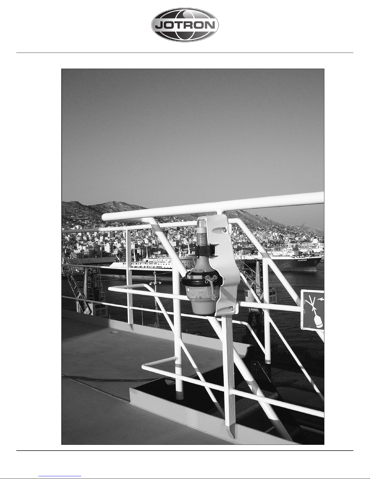
4.1.1 FLOAT FREE BRACKET FB6, FB5 AND FB4
When the Tron 40S MkII is mounted in the float-free bracket, FB6, FB5 or FB4,
it will operate as an automatic float free unit. Since the release of the EPIRB will
be automatic it is important to mount the bracket in a place where there are no
obstacles that can endanger the automatic release of the EPIRB. The location
where the bracket is mounted should be as high as possible on the vessel, and
well protected from environmental conditions such as direct sea-spray, chemicals, oil, exhaust and vibrations. The location must also be easily accessible for
testing and maintenance.
4.1.2 FLOAT FREE BRACKET FBH4
See figure 7.8 for installation.
The float free bracket FBH4 must be connected to the fixed installation (230V
AC, 10A) through the thermostat connection box according to the connection
diagram below.
Figure 4.1.2 Connection diagram FBH4
230 V AC, 10 A
HEATING ELEMENT
Thermostat
WARNING:
DO NOT INSTALL THE EPIRB NEAR STRONG
MAGNETIC FIELDS THAT COULD ACTIVATE THE BEACON
24
Page 25

82819_UM_40SMkII_H
www.jotron.com
4.1.3 MANUAL BRACKET MB5 AND MB4
When the Tron 40S MkII is mounted in the MB5 or MB4 bracket, it will operate
as a manual unit. This bracket is the same as the FB6, FB5 and FB4 bracket
but does not have the hydrostatic release mechanism. This bracket is typically
used to store the EPIRB inside the wheelhouse or other protected areas of the
ship. When the Tron 40S MkII is mounted in the MB5 or MB4 bracket, it must be
manually removed before any operation can take place, therefore the bracket
should be mounted in an easily accessible place where it can be removed in a
hurry in case of an emergency.
4.1.4 MOUNTING THE FB6/FB5/MB5/FB4/FBH4/MB4 BRACKETS
See figure 7.8
The bracket is mounted with 4x6mm bolts according to the drawing. Use the
bolts supplied with the bracket. The bracket could be mounted in either a vertical or horizontal position, whichever is the best regarding maintenance and
operation.
25
Page 26

82819_UM_40SMkII_H
www.jotron.com
5 OPERATION INSTRUCTIONS
The Tron 40S MkII is designed to be operated either manually or automatically.
The EPIRB is always armed, that is the EPIRB will automatically start to transmit when the EPIRB is out of the bracket and deployed into water. In the lower
part of the EPIRB there is an automatic safety switch. This switch prevents the
seawater contacts from operating the EPIRB (caused by ice, sea-spray etc.) as
long as the EPIRB is placed in its bracket. See chapter 6.5 Error codes.
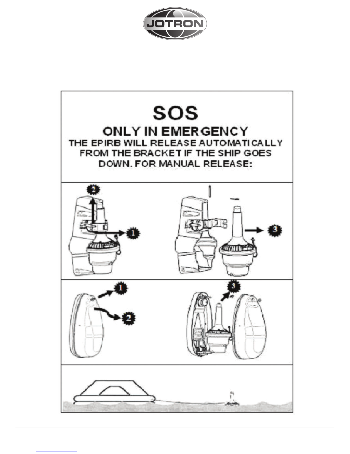
5.1 MANUAL OPERATION
See figure 7.2
For operation of the beacon in the bracket please follow instructions 1 to 3.
To manually remove the beacon from the bracket, pull out the locking pin on
the clamp and open the retaining rod that holds the beacon.
Tie the beacon lanyard to you or to the survival craft and then follow instructions 1 to 6, or put beacon in the water to activate it.
It is not recommended to operate the beacon inside a life raft or under a cover
or canopy. Do NOT tie the lanyard to the ship in distress, as this will prevent the
unit to functioning if the ship sinks.
1. Break the seal and pull the locking pin holding the main activator
switch.
2. Push slider to move switch to ON position.
3. The switch is spring-loaded and will automatically go to the ON posi-
tion.
4. The strobe light, located at the top of the EPIRB, will start flashing in dicating that the EPIRB is operating.
5. If possible keep the EPIRB in an open area, away from any metal ob
jects (ship construction etc.) that may limit the satellite coverage.
6. Transmission can be stopped by turning the switch to READY position.
WARNING
USE ONLY DURING SITUATIONS
OF GRAVE AND IMMINENT DANGER
26
Page 27

82819_UM_40SMkII_H
www.jotron.com
5.2 AUTOMATIC OPERATION (FB4/FBH4/FB5/FB6)
See figure 7.3
1. The Tron 40S MkII will automatically release from the bracket, float to the
surface and start to transmit when the EPIRB, in its bracket is deployed into
water at a depth of app. 2-4 meters (6 - 13 feet).
2. Alternatively the EPIRB can be manually released from the bracket and put
into the water.
3. Transmission will continue until the EPIRB is lifted out of the water, and dried
off. The transmission can also be stopped by placing the EPIRB in the bracket.
5.3 MANUAL TEST OF THE EPIRB
See figure 7.4
To perform the self-test, the EPIRB has to be removed from the bracket.
FB4 bracket: Remove EPIRB from the bracket by pulling out the locking pin on
the clamp and open the retaining rod that holds the beacon.
FB6/FB5 bracket: Release top cover by removing the locking split pin and
special washer.
1. Push and hold switch in TEST position for 15 seconds.
Keep hands and other objects away from the upper part of the EPIRB (away
from the antenna).
2. Test passed after one single flash only!
See chapter 6.4, EPIRB module error message
WARNING
The self-test should be performed only
within the first 5 minutes of any hour.
WARNING
The EPIRB can drop out of the FB6/FB5
bracket when releasing top cover
27
Page 28

82819_UM_40SMkII_H
www.jotron.com
4. Release the switch and put the EPIRB back into the bracket. What the selftest actually does is first to wait some seconds to allow the reference oscillator
inside the EPIRB to start up. Then a short burst is transmitted by the 121,5 MHz
transmitter, while the output level of the transmitter is checked. Finally, a test
signal is transmitted by the 406 transmitter. During this test signal the battery
voltage, output power and frequency is checked.
While testing the 406 MHz transmitter a test message is transmitted, this test
message is coded with a special synchronisation code and will not be detected
by the COSPAS/SARSAT satellites. The purpose of this test message is to control the actual coding of the EPIRB. This can be done with the Jotron AS test unit
Tron UniDEC or another EPIRB tester.
28
Page 29

82819_UM_40SMkII_H
www.jotron.com
6 MAINTENANCE AND TROUBLESHOOTING
6.1 EPIRB MODULE / BATTERY MODULE
The EPIRB shall be tested and approved as required by SOLAS regulation
IV/15.9.2 of SOLAS 1974 as amended with, in accordance with MSC/Circ.1039
guidelines for shore-based maintenance of Satellite EPIRBs within 5 years if:
Passenger ships (>12 passengers) and cargo ships (>300GT) engaged in international voyages, shall perform Shore-Based Maintenance (SMB) as follows:
- Latest by the date of the EPIRB label with this text, or the battery label,
which ever is first.
- When this EPIRB becomes due for SBM in accordance with national require
ments.
6.1.1 CHANGE OF BATTERY
If the Tron 40S MkII is the main EPIRB on board the ship, the rules of SBM apply,
and the battery must be changed at an SBM authorized workshop.
If the Tron 40S MkII is the second EPIRB on board the ship, authorized personnel can change the battery on board.
6.1.2 REPLACING THE BATTERY MODULE
See figure 7.7
To change the battery, the lower Tron 40S MkII assembly is replaced with a new
one. The battery module consists of the complete lower half of the Tron 40S
MkII and is to be replaced every 5 years. The marking on the battery module
shows the expiry date. A new battery comes complete and is easily replaced by
opening the equator ring between the top and bottom of the EPIRB. The battery must be replaced if the EPIRB is activated for any purpose other than test.
Replacing the battery module should be done by a Jotron AS authorised SBM
provider. Your closest Jotron AS agent with TronSTAT facilities has been specially
trained to perform the necessary operation and is also able to do an extended
test of the EPIRB, ensuring that the EPIRB operates within the specifications.
1. Remove the EPIRB from its bracket .
2. Remove the equator ring by pressing it out from the housing.
3. Separate the two halves of the EPIRB housing.
4. Unplug the 6-pin connector that comes from the lower EPIRB housing.
5. Ensure that the new battery module is marked with p/n 83056 and has a
29
Page 30

82819_UM_40SMkII_H
www.jotron.com
new expiration date, approximately 5 years from purchase.
6. Fit a new gasket on top of the battery module and reconnect the 6-pin
connector, be sure that the connector is fitted properly. A noticeable
«click» should be heard when the connector is in place.
7. Please make sure that the enclosed silica-gel bag is fastened inside the
emergency product, with the supplied strips into/between holes in the black
cover.
IMPORTANT: Cut the strips p/n 96898 after mounting of silica gel to avoid the
strips to come between rubber gasket and top housing.
8. Please also fit the enclosed anti corrosion adhesive tape to the inside of
the battery before assembling the unit.
9. Orientate the two halves of the EPIRB the following way:
An orientation tab is fitted on both halves of the EPIRB, these tabs must be
placed carefully on top of each other.
10. Make sure that the gasket is properly in place, and replace the equator ring
using a special tool to tighten it together.
11. Replace the U-shaped bolt and a new split pin to secure the bolt in the
equator ring.
12. Remount EPIRB in its bracket.
6.1.3 BATTERY DISPOSAL
Dispose in accordance with applicable regulations, which vary from country to country.(In most countries, the thrashing of used batteries is forbidden
and the end-users are invited to dispose of them properly, eventually through
non-profit organizations, mandated by local governments or organized on a
voluntary basis by professionals).Lithium batteries should have their terminals
insulated prior to disposal.
6.1.4 INCINERATION
Incineration should never be performed by battery users but eventually by trained professionals in authorized facilities with proper gas and fumes treatment.
30
Page 31

82819_UM_40SMkII_H
www.jotron.com
6.1.5 LAND FILLING
Leachability regulations (mg/l)
Component Leachability EC limit EPA Other*
Iron 100 5
Nickel 100 500 2 0,5
* Applicable to France
6.1.6 RECYCLING
Send to authorized recycling facilities, eventually through a licensed waste
carrier.
6.2 HYDROSTATIC RELEASE REPLACEMENT
For details see chapter 6.2.1 and 6.2.2.
6.2.1 REPLACING THE RELEASE MECHANISM IN FB4/FBH4 BRACKET
See figure 7.5
The hydrostatic unit fitted on the float free bracket [FB4/FBH4] must be replaced every 2 years. Marking the expiry date on the hydrostatic unit.
The hydrostatic comes complete with a new bolt and accessories.
1. Remove the EPIRB from its bracket by pulling out the locking pin on the
clamp and open the retaining rod that holds the beacon.
2. Unscrew the plastic bolt (1) by screwing it counter clockwise and remove
the hydrostatic release mechanism (2).
3. Check expiration date on the new hydrostatic release mechanism. The date
should be approximately 2 years from the date of installation.
4. Mount the new hydrostatic release mechanism. The unit is fixed to the bra-
cket with a plastic bolt containing washer, rubber seal, washer, O-ring.
5. Secure the plastic bolt by hand force only!
31
Page 32

82819_UM_40SMkII_H
www.jotron.com
6.2.2 REPLACING THE RELEASE MECHANISM IN FB6/FB5 BRACKET
See figure 7.6
1. Release FB6/FB5 top cover by removing the locking split pin and special
washer (a).
2. Press down the spring-loaded bracket plate and remove the hydrostatic
unit by sliding it out of its locking slot (b).
3. Check the expiry date of the new hydrostatic release mechanism (c). The
date should be approximately two years from the date of installation.
4. Install a new hydrostatic unit by pressing down the spring loaded bracket
plate and sliding the unit into its locking slot (b).
5. Replace the EPIRB and the FB6/FB5 top cover.
Be sure that the top cover is locked at the bottom end and that the top end
are fixed at hydrostatic release mechanism rod.
Replace the special washer and the locking split pin (a).
6.3 MAINTENANCE OF EPIRB
Every Month: Perform EPIRB self-test. See chapter 6.3.What the self-test actually does is to send out a short test signal on 121,5 and 406,037MHz, testing
the output of the transmitter. While transmitting the test signal, the battery
voltage, output power and phase lock is tested. During the test of the 406MHz
transmitter a test message is transmitted, this test message is coded with a
special synchronization code and will not be recognized as real alert by the
COSPAS/SARSAT satellites. Carry out visual inspection for defects on both the
Tron 40S MkII and Bracket. The Tron 40S MkII should be easily removed and
replaced in the Bracket. Make sure that the Tron 40S MkII and Bracket is not
painted or otherwise covered with chemicals, oil, etc. Check the expiry date of
the EPIRB Battery and the Hydrostatic Release Mechanism. Check the presence of a firmly attached lanyard in good condition and that it is neatly stowed
and is not tied to the vessel or the mounting bracket. If the Tron 40S MkII is the
main EPIRB on board, these rules must be followed:
WARNING
The EPIRB can drop out of the FB6/FB5
bracket when releasing top cover
32
Page 33

82819_UM_40SMkII_H
www.jotron.com
Every 12th month:
If the Tron 40S MkII is the main EPIRB on board and the ship falls under the
SOLAS regulations of SBM, these rules must be followed: Perform extended
annual test according to IMO’s MSC/Circ.1040 (Annual testing of 406 MHz satellite EPIRBs) as required by SOLAS IV/15.9.This test can be carried out by one
of Jotron AS authorized representatives or any other service provider in possession of a Tron UNIDEC or any other Cospas/Sarsat EPIRB tester/decoder.
Every 2ndYear:
Hydrostatic Release Mechanism including Plastic Bolt on the Float Free Brackets must be replaced. (Check expiry date on label).
Every 5thYear:
See chapter 6.1
6.4 EPIRB ERROR MESSAGES
If the self-test detects a fault in the EPIRB module one or more of the following
indications are shown:
Number of flashes: Fault indication:
1 NONE
2 Low power on 406 MHz transmitter
3 Low battery voltage
4 Low power on 121.5 MHz transmitter
5 PLL on 406 MHz transmitter out of lock
6 PLL on 121.5 MHz transmitter out of lock
7 EPIRB module not programmed or programming not
complete.
33
Page 34

82819_UM_40SMkII_H
www.jotron.com
34
Page 35

82819_UM_40SMkII_H
www.jotron.com
7 FIGURES
7.1 SIGNAL DETECTION
See chapter 1.2.1 and 1.2.2
Figure 7.1.a
Figure 7.1.b
35
Page 36

82819_UM_40SMkII_H
www.jotron.com
7.2 MANUAL OPERATION
See chapter 5.1
Figure 7.2
36
Page 37

82819_UM_40SMkII_H
www.jotron.com
7.3 AUTOMATIC OPERATION
See chapter 5
Figure 7.3
7.4 SELF TEST
See chapter 5.3
Figure 7.4
37
Page 38

82819_UM_40SMkII_H
www.jotron.com
7.5 REPLACING THE RELEASE MECHANISM IN FB4/FBH4 BRACKET
See chapter 6.2.1
Figure 7.5
7.6 REPLACING THE RELEASE MECHANISM IN FB6/FB5 BRACKET
See chapter 6.2.2
Figure 7.6.a, b and c
38
Page 39

82819_UM_40SMkII_H
www.jotron.com
7.7 REPLACING THE BATTERY MODULE
See chapter 6.1.2
Figure 7.7.a
39
Page 40

82819_UM_40SMkII_H
www.jotron.com
Figure 7.7.b
40
Page 41

82819_UM_40SMkII_H
www.jotron.com
7.8 MOUNTING OF BRACKETS
Figure 7.8
41
FB4
FB5
FB6
Page 42

82819_UM_40SMkII_H
www.jotron.com
8 SERVICE AGENTS
Please look at www.jotron.com for Marine Service Agents.
Jotron Group subsidiary companies:
Jotron UK Ltd.
Crosland Park, Off Crowhall Road
Cramlington
Northumberland NE23 1LA
United Kingdom
Tel +44 1670 712000
Fax +44 1670 590265
E-mail: sales@jotron.co.uk
Jotron Asia Pte. Ltd.
Changi Logistics Center
19 Loyang Way #04-26
Singapore 508724
Tel +65 65426350
Fax +65 65429415
E-mail: sales@jotron-asia.com
Jotron USA, Inc.
10645 Richmond Avenue, Suite 140
Houston, TX 77042
USA
Tel +1 713 268 1061
Fax +1 713 268 1062
E-mail: contact.us@jotron-usa.com
42
Page 43

43
Page 44

www.jotron.com
 Loading...