

Page 1
www.jotron.com
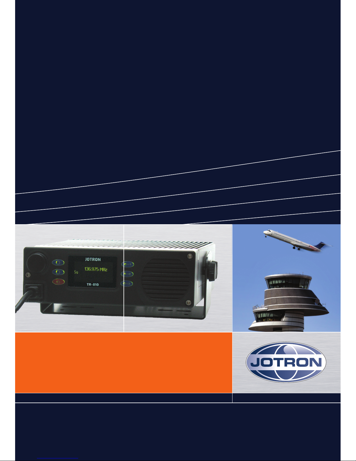
OPERATOR AND INSTALLATION MANUAL
TR-810
VHF AM GROUND TO AIR COMMUNICATION RADIO
Page 2

84417_O&I_TR-810_C Introduction
Page iii
The equipment is designed to meet the essential requirements of European Directives
1999/5/EC, 89/336EEC as amended by Directive 93/68/EEC and 72/23/EEC
The following standards are applied:
EMC: EN 301 489-22 v. 1.3.1
FCC part 15 and part 87
Health and Safety: IEC 60945 ed.4 and EN60950-1
Radio specifications: EN 300 676-1 v.1.4.1
For an updated list of approvals and statements of conformity, these are available on:
www.jotron.com
TECHNICAL MANUAL
TR-810
VHF TRANSCEIVER
Page 3

84417_O&I_TR-810_C Introduction
Page iv
BITE
Built In Test Equipment
bps
Bits Per Second.
DSP
Digital Signal Processor
ETSI
European Telecommunication Standardisation Institute
ICAO
International Civil Aviation Organization
IEC
International Electro-technical Commission.
OCP
Operators Control Panel (In this manual: Front module)
PA
Power Amplifier
PSU
Power Supply Unit. Separate unit to power the equipment.
PTT
Push To Talk
RF
Radio Frequency
S/N
SIGNAL- TO-NOISE RATIO
VSWR
Voltage Standing Wave Ratio
Page 4

84417_O&I_TR-810_C Introduction
Page v
NO
INIT
DATE
PAGE(S)
VERSION
REASON FOR CHANGE
1
ES
09.05.08
Total: 33
84417_OM_TR-810_A
New manual
2
ES
08.07.08
1-1, 2-1
84417_OM_TR-810_B
Change in Tables
3
ES
14.10.08
ALL
Total:32
84417_O&I_TR-810_C
Operation and
Installation manual
4
5
6
7
8
9
10
11
12
13
14
15
16
17
18
19
20
Page 5

84417_O&I_TR-810_C Introduction
Page vi
The information in this book has been carefully checked and is believed to be accurate.
However, no responsibility is assumed for inaccuracies.
Jotron AS reserves the right to make changes without further notice to any products or
modules described herein to improve reliability, function or design. Jotron AS does not
assume any liability arising out of the application or use of the described product.
This equipment contains CMOS integrated circuits. Observe handling precautions to avoid
static discharges which may damage these devices.
Some RF semiconductor devices used in this equipment may contain Beryllium Oxide. If
inhaled, dust from this oxide can be toxic. No danger will arise from normal handling but no
attempt should be made to tamper with these devices. On no account must these transistors
be destroyed or discarded with industrial or domestic waste, but should be returned to the
manufacturers for subsequent disposal.
Page 6

84417_O&I_TR-810_C Introduction
Page vii
Connectors and cables
Do not force plugs in place, as this may damage the pins in the plugs.
Do not pull the cables when removing connectors from the TR-810, take instead a firm grip
around the connector, press in the locking pin and pull.
Display and front panel
Avoid touching the display with sharp objects, as scratches can reduce the visibility.
Storage and safe handling
Storage temperature is between -40C to + 70 C.
Cleaning of the equipment can be done with a cloth soaked in a mixture of ordinary dishdetergent and water.
1. Do not place liquid-filled containers on top of the equipment.
2. Immediately turn off the power if water or other liquid leaks into the equipment.
Continued use of the equipment can cause fire or electrical shock. Contact Jotron
AS for service.
3. Immediately turn off the power if the equipment is emitting smoke or fire.
4. Do not operate the equipment with wet hands.
Page 7
84417_O&I_TR-810_C Introduction
Page viii
This device complies with part 15 of the FCC Rules. Operation is subject to the following two
conditions: (1) This device may not cause harmful interference, and (2) this device must
accept any interference received, including interference that may cause undesired
operation.
Changes or modifications not expressly approved by the party responsible for compliance
could void the user's authority to operate the equipment.
This equipment has been tested and found to comply with the limits for a Class B digital
device, pursuant to part 15 of the FCC Rules. These limits are designed to provide reasonable
protection against harmful interference in a residential installation. This equipment
generates, uses and can radiate radio frequency energy and, if not installed and used in
accordance with the instructions, may cause harmful interference to radio communications.
However, there is no guarantee that interference will not occur in a particular installation.
If this equipment does cause harmful interference to radio or television reception, which can
be determined by turning the equipment off and on, the user is encouraged to try to correct
the interference by one or more of the following measures:
--Reorient or relocate the receiving antenna.
--Increase the separation between the equipment and transceiver.
--Connect the equipment into an outlet on a circuit different from that
to which the transceiver is connected.
--Consult the dealer or an experienced radio/TV technician for help.
Page 8

84417_O&I_TR-810_C Introduction
Page ix
1 INTRODUCTION .................................................................................................................. 1-1
1.1 MODELS COVERED BY THIS MANUAL .............................................................................................. 1-1
1.2 LAYOUT OF THE TRANSCEIVER ....................................................................................................... 1-2
1.3 APPLICATIONS ............................................................................................................................ 1-2
2 TECHNICAL SPECIFICATIONS ................................................................................................ 2-1
2.1 GENERAL SPECIFICATION, TR-810 ................................................................................................. 2-1
3 FUNCTIONAL DESCRIPTION ................................................................................................. 3-1
3.1 FRONT MODULE CONTROLS .......................................................................................................... 3-1
3.1.1 Display............................................................................................................................. 3-1
3.1.2 Scroll/Select switch and Navigation buttons A, B and C ................................................. 3-2
3.1.3 ON/OFF button ............................................................................................................... 3-2
3.1.4 Front Mic/Headset connector ......................................................................................... 3-2
3.1.5 Preset channel buttons ................................................................................................... 3-3
3.2 TRANSCEIVER, REAR CONNECTIONS ................................................................................................ 3-3
3.2.1 Antenna connector (50 ohm N) ...................................................................................... 3-3
3.2.2 DC Connector .................................................................................................................. 3-3
3.2.3 I/O connector (RJ45) ....................................................................................................... 3-4
3.2.4 MIC II connector (RJ45) ................................................................................................... 3-4
4 INSTALLATION .................................................................................................................... 4-1
4.1 COMPASS SAFE DISTANCE ............................................................................................................. 4-1
4.2 INTRODUCTION. ......................................................................................................................... 4-1
4.3 INITIAL INSPECTION ..................................................................................................................... 4-1
4.4 INSTALLATION OF TR-810 ............................................................................................................ 4-2
4.4.1 Split installation parts ..................................................................................................... 4-2
4.4.2 Measures of TR-810 ........................................................................................................ 4-3
4.4.3 Desktop Mounting .......................................................................................................... 4-4
4.4.4 Flush mounting ............................................................................................................... 4-5
4.5 ANTENNA CONNECTORS ............................................................................................................... 4-6
4.6 DC CONNECTION ........................................................................................................................ 4-6
4.7 REMOTE SIGNALS ........................................................................................................................ 4-6
5 OPERATING INSTRUCTIONS ................................................................................................. 5-1
5.1 INTRODUCTION .......................................................................................................................... 5-1
5.1.1 Note on frequency setting .............................................................................................. 5-2
5.2 USER MENU – TRANSCEIVER (RESTRICTED ACCESS LEVEL) .................................................................. 5-3
5.3 USER MENU – TRANSCEIVER (NON-RESTRICTED ACCESS LEVEL) ........................................................... 5-4
5.4 USER MENU – TRANSCEIVER (TECHNICIAN) ..................................................................................... 5-4
5.5 SETTING, INFORMATION AND CONFIGURATION MENUS – TRANSCEIVER ................................................ 5-5
5.6 SERVICE INFORMATION MENUS – TRANSCEIVER ............................................................................... 5-6
5.7 BITE INFORMATION MENUS – TRANSCEIVER .................................................................................... 5-6
6 ERROR CONDITIONS AND CORRECTIVE ACTIONS ................................................................. 6-1
7 LIST OF TABLES AND FIGURES .............................................................................................. 7-1
Page 9
84417_O&I_TR-810_C Introduction
Page 1-1
1 Introduction
1.1 Models covered by this manual
The following models / variants are covered by this operator manual
Model
P/N
Accessories
Output
Frequency range
Modes
TR-810 Transceiver
Vehicle version
83200
See Table 1.1-2
10 Watt
118-137 MHz
AM
TR-810 Transceiver
Desktop version
83200
See Table 1.1-2
10 Watt
118-137 MHz
AM
Table 1.1-1, Radio models
Accessory
X = Standard supply O = Optional supply
Part
number
TR-810
Vehicle version
TR-810
Desktop version
5m extension cable for split mount
84317 X X
Hand microphone
84092 X X
Console bracket
84084 X X
Lock screws
84086 X X
Front module bracket (for split mount)
84391 X X
Operation and Installation manual
84417 X X
Antenna with cable (Vehicle kit)
97976 X
Antenna adapter FME - BNC
84605 X
DC cable with fuses for vehicle mount
84329 X
Power AC/DC with connector
84330 X
DC/DC converter with separation
84545 X
Antenna adapter BNC - N
80577 X
Front cover plate with flange (for split mount)
84082 O
Console cover plate (for split mount)
84416 O
Base antenna
91794 O
Coax cable RG-213 – 30m
97898 O
N-connector for RG-213
98244 O
Antenna ½``flammable retardant cable
82907 O
N-connector for ½``flammable retardant cable
82908 O
Antenna lightning protector
80322 O
Technical manual
84096 O O
Table 1.1-2, Accessory list
Page 10
84417_O&I_TR-810_C Introduction
Page 1-2
1.2 Layout of the transceiver
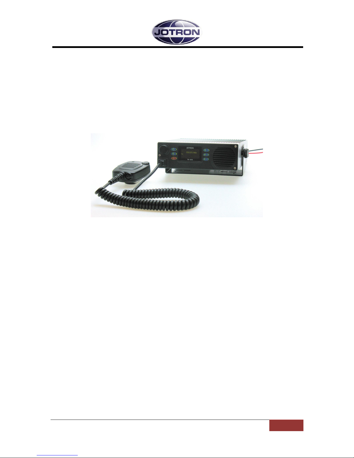
The TR-810 VHF AM transceiver is designed for use in ground to air communication in the
118-137MHz air band, with selectable channel spacing, 8.33KHz* or 25KHz. The transceiver
operates in accordance to ICAO recommendations and conforms to the requirements of
European Telecom Standard Institute, ETSI, EN 300 676 standard. The transceiver will be
delivered with 10 Watt, 40 Watt PEP, output power.
*) 8.33KHz are only applicable outside USA and Canada
Figure 1.2-1, Transceiver, TR-810 with microphone
1.3 Applications
The TR-810 AM transceiver can be used for ground to air voice and can be operated in the
following modes:
Locally, mounted into a vehicle, with a microphone connected to the front module
connector or to the transceiver unit micII connector. An external loudspeaker can be
connected to the transceiver unit I/O connector.
Locally, mounted as a desktop, with microphone and/or headphone connected to the
front module connector or the microphone connected to the transceiver unit rear
connector. An external loudspeaker can be connected to the transceiver unit I/O
connector.
Locally, flush mounted on a horizontal or vertical plate, with microphone and /or
headphone connected to the front module connector or the microphone connected
to the transceiver unit micII connector. An external loudspeaker can be connected to
the transceiver unit I/O connector.
Page 11

84417_O&I_TR-810_C Technical SPECIFICATIONS
Page 2-1
2 Technical SPECIFICATIONS
2.1 General specification, TR-810
TR-810
Radio performance
EN 300 676 v.1.3.1
Temperature range
-20°C to +55°C (operating) -40°C to +70°C (storage)
Humidity
90% @+40°C (non condensing)
Shock & Vibration
Transport: EN 300 019-2-2
Shock & Vibration
Ground Vehicle installations: EN 300 019-2-5
Shock & Vibration
Portable and non-stationary use: EN 300 019-2-7
Safety
According to EN/IEC 60950
EMC
EN 301 489-1 v.1.5.1, EN 301 489-22 v.1.3.1 , IEC 60945
MTBF
>10 years / unit
MTTR
<30 minutes at lowest replaceable unit
Transceiver
AM 25 kHz
AM 8.33 kHz (applicable outside USA and Canada)
Frequency response
300-3400 Hz
350-2500 Hz
Effective bandwidth <6dB @
+/- 8.5kHz
+/- 4 kHz
Supply voltage, DC
12 - 28VDC negative ground +/- 10%
Power consumption
At 10W, 80%modulation: < 60W
Frequency range
118-137 MHz
Frequency stability
± 1.0ppm
Data ports
RS232 for service only
BITE monitoring
VSWR, Voltages, Currents, Levels, Lock detect, Temperature, Output power, External alarm
Weight Transceiver unit
1.95Kg
Dimension Transceiver unit
184mm (W) * 241mm(D) * 72,8mm (H)
TX Output power
10W ± 1dB, adjustable. (40W PEP). Output is reduced automatically depending of BITE measure.
TX Modulation
AM up to 90%. Modulation level adjustable from front panel.
TX Distorsion
< 5% @ 90% modulation
TX LF compression VOGAD
30dB with less than 10% change in modulation
TX Hum and noise level
> 40dB below @ 90% modulation
TX Keying time
< 20.0ms
TX Conducted spurious emission
< -70dBm
TX Permissible input level
5V EMF
TX THD
< 5%, 90% mod
TX Mic input
Dynamic/Electret. Sensitivity 1.9mV
TX Intermodulation attenuation
> 40dB with a frequency offset of ± 150kHz
RX Adjacent channel rejection
>80dB
>65dB
RX THD
< 100µV, 1kHz
RX Sensitivity @1V / 30% pd
10dB SINAD (CCITT)
RX Image and IF frequency response
>100 dB
RX Intermodulation immunity
>80 dBc
RX Squelch operation
Adjustable -1µV pd. to 25µV pd., Hysteresis:< 3dB, Opening/Closing: < 50ms
RX Audio AGC
30% - 90%, <3dB variation
RX Audio output
Built in speaker: >4W
RX Headphone
8 - 32Ω >100mW
RX External speaker
>4W @ 4Ω, adjustable volume from front panel
RX Signal / Noise
>45dB on any output @100V, 30%, 1kHz
RX Monitor output
600Ω (unbalanced) -7dBm @ 90% modulation
RX Harmonic distortion
<3% @90% AM (line output)
RX Cross modulation
>90dB @ 1MHz offset
RX Blocking
>95dB @1MHz offset
RX Dynamic range
>110dB
RX Spurious response rejection
>90dB
Page 12

84417_O&I_TR-810_C Functional description
Page 3-1
3 Functional description
3.1 Front module controls
3.1.1 Display
The display shows the most important operational parameters, selected channel and
frequency.
In addition, the display will show various menus, submenus and operational parameters to
be accessed by the Scroll/Select switch and Navigation buttons A, B and C.
The bottom line of the display will show icons to indicate different status:
Indicates that the key button on the microphone is pressed, and the radio is
transmitting.
Indicates that the radio transmitter has decreased the output level to Low Power.
See chapter 5.7 for details.
Indicates that the Squelch is open and/or a signal is received.
Indicates an Alarm condition. An alarm text will be shown at the right side of this
symbol.
Scroll /Select
switch (SW)
Navigation
button (A)
Display
Preset Channel
buttons
Internal
loadspeaker
Navigation
button (B)
Navigation
button (C)
Mic/Headset
connector
TX
LP
SQ
!
Figure 3.1-1, Front module controls
Page 13

84417_O&I_TR-810_C Functional description
Page 3-2
3.1.2 Scroll/Select switch and Navigation buttons A, B and C
The Scroll/Select switch together with the navigation buttons, A, B and C, are used to
navigate through the menus. The Scroll/Select switch has three actions: It can be turned
clockwise, anti-clockwise, or momentarily pressed.
In general the use of the navigation buttons are:
A has two functions: Select Channel or One step back
B has two functions: Squelch on/off or Enter/Confirm a selected submenu
C has two functions: Enter Main menu or Power on/off
SW Scroll/Select right: Increase a value (up)
SW Scroll/Select left: Decrease a value (down)
SW Scroll/Select press: Enter/Confirm
The user interface will indicate which navigation button to use.
3.1.3 ON/OFF button
Navigation button C.
To switch the transceiver ON, press and hold button for 1 second.
To switch the transceiver OFF, press button once to enter the Main menu. Then press and
hold the button for 5 seconds.
3.1.4 Front Mic/Headset connector
The front Mic/Headset connector is used for multiple purposes. First it is used to connect a
microphone and/or a headset to the front module of the transceiver for local operation. The
headset output contains the sidetone generated from the output of the transmitter together
with the received audio when the transmitter is not keyed.
In addition the Mic/Headset connector has a RS232 serial line that can be used to control
radio parameters from an external unit, or to upload new firmware into the radio unit for
future upgrades. A service dongle can be inserted to access the service menu.
Microphone Connector Front
Name
PIN
Purpose
MIC. INPUT
1 MIC. GND
2 Headset
3
RS232
4
RS232 TD
RS232
5
RS232 RD
KEY 6 Grounding this pin will key the transmitter
+12VDC
7
+12 VDC to external equipment (10mA)
GND
8
Common ground
Table 3.1.4-1, Front Mic/Headset connector, pin out
Page 14

84417_O&I_TR-810_C Functional description
Page 3-3
3.1.5 Preset channel buttons
These buttons are used to bring already stored channels.
3.2 Transceiver, rear connections
Figure 3.2-1, TR-810 transceiver unit, rear view
3.2.1 Antenna connector (50 ohm N)
Interface to the antenna cable for the transceiver Connector (50 ohm BNC).
This connector is connected to the antenna relay internally in the transceiver unit.
3.2.2 DC Connector
The DC wires are connected to the external DC supply (+12V to + 28V 10%), or directly to
the cars battery via a separate external fuse.
Red wire is the positive connection and Black wire is the negative.
A thin Green wire is together with the DC input wires. This wire can be connected to +
voltage through the ignition key, to automatically turn the TR-810 off when the ignition is
turned off.
To ignore this possibility, this wire has to be connected to a constant + voltage.
DC
Connector
Mic II
connector
I/O
connector
Antenna
connector
Page 15

84417_O&I_TR-810_C Functional description
Page 3-4
DC Connector
Name
PIN
Purpose
Red wire
1
Connected to + DC voltage
Black wire
2
Connected to minus
Green wire
3
Ignition + DC voltage sense
Table 3.2.2-1, DC connector, pin out
3.2.3 I/O connector (RJ45)
The transceiver unit I/O connector is used for multiple purposes described in the table.
I/O Connector
Name
PIN
Purpose
EX-SPEAKER
1
To external speaker.
EX-SPEAKER
2
To external speaker.
MONITOR
3
To tape recorder etc. 600Ω unbalanced
LOW POWER
4
Grounding this pin will force the transmitter to
low power (Gas alarm)
NC 5 Not in use
MUTE
6
Used to mute external equipment. Triggered by
squelch
+12VDC
7
+12 VDC to external equipment (10mA)
GND
8
Common ground
Table 3.2.3-1, I/O connector, pin out
3.2.4 MIC II connector (RJ45)
The microphone can be connected to this connector if it is convenient to have the microphone
connected at the rear side of the transceiver unit. See chapter 4.7 and 5.5 for selecting an external
microphone.
Rear mic. Connector
Name
PIN
Purpose
MIC. INPUT
1 MIC. GND
2 Headset
3 NC 4 Not in use
NC 5 Not in use
KEY 6 Grounding this pin will key the transmitter
+12VDC
7
+12 VDC to external equipment (10mA)
GND
8
Common ground
Table 3.2.4-1, MIC II connector, pin out
Page 16

84417_O&I_TR-810_C Installation
Page 4-1
4 Installation
4.1 Compass safe distance
The Compass safe distance for the TR-810 is minimum 110cm.
4.2 Introduction.
The procedures for installing the transceiver are described in Table 4.2-1 below.
It is recommended that these procedures are completed in the order shown.
Procedure
Reference
1
Initial inspection
4.3 2 Install equipment
4.4 4 Connect remote connectors as required
4.7 5 Connect antenna
4.5 6 Connect DC supply
4.6
Table 4.2-1, Installation procedures
4.3 Initial inspection
Items included for a TR-810 transceiver
1
TR-810 transceiver
2
CD with Operators Manual
3
Accessories ordered according to model and installation. See Table 1.1-2,
Accessory list
Table 4.3-1, Inspection procedures
On receipt of the radio unit, remove all transit packaging and check that there is no damage
to the equipment. If damage is evident, contact Jotron AS immediately and retain the
original transit packaging.
Page 17

84417_O&I_TR-810_C Installation
Page 4-2
4.4 Installation of TR-810
4.4.1 Split installation parts
Figure 4.4.1-1 shows some extra parts used for split installation. The TR-810 can be mounted
as a Mobile radio, Desk top or Flush mounted into a horizontal or vertical area. The front
module can be mounted separately away from the transceiver unit using an extension cable
and a mounting plate or a bracket.
Item
number
Document
number
Title
Quantity
1
82767
TRANSCEIVER UNIT W/ DESKTOP BRACKET
1 2 84082
FRONT COVER PLATE W/FLANGE
1 3 84416
CONSOLE MOUNTING PLATE FRONT MODULE
1 4 84414
BRACKET FRONT MODULE
1 5 82276
DIN912-CYL HEAD UMBRAKO M4X10
2
Figure 4.4.1-1, Examples of various parts used for split installation
Page 18

84417_O&I_TR-810_C Installation
Page 4-3
4.4.2 Measures of TR-810
Figure 4.4.2-1, Measures of TR-810
Page 19

84417_O&I_TR-810_C Installation
Page 4-4
4.4.3 Desktop Mounting
Figure 4.4.3-1, Standard desktop mounting
Figure 4.4.3-2, Split desktop mounting
Page 20

84417_O&I_TR-810_C Installation
Page 4-5
4.4.4 Flush mounting
Figure 4.4.4-1, Standard flush mounting
Hole in desk or wall for the connection cable between
front module and transceiver unit
Figure 4.4.4-2, Split flush mounting
Page 21

84417_O&I_TR-810_C Installation
Page 4-6
4.5 Antenna connectors
The antenna should be of good quality with regards to gain and VSWR to obtain maximum
performance. Make sure that the VSWR on the antenna is low, and that the cable from the
transmitter to the antenna is of good quality to avoid mismatch and unnecessary losses.
A cable loss of 1 dB is the same as reducing the power output of a 10W transmitter to less
than 8.5W. Similarly, a cable loss of 2 dB is the same as reducing the output power to less
than 7W.
In areas were thunderstorms and lightning is a problem, surge arrestors should be mounted
between the antenna connector and the antenna cable. The arrestors should be of good
quality and be capable of handling the output power of the transmitter.
The antenna input of the transceiver is the BNC-type antenna connector on the back of the
transceiver unit.
4.6 DC connection
Refer to chapter 2.1 for voltage limits.
4.7 Remote signals
Several remote signals are available on the rear interfaces of the transceiver unit.
These signals can be grouped into: Audio signals, Key signals and I/O signals.
Note, for all interface signals, RJ45 connectors are used. As far as practically possible, the
pairs used on a standard ethernet connection are used when a signal is input/output as a
pair to the radio (e.g. audio lines).
For interconnections between the front module and transceiver unit, standard Cat5E,
ethernet cable should be used. This is a good quality, screened cable, with 1 to 1
connections between the two connectors.
Refer to chapter 3.1.4, 3.2.3 and 3.2.4 for an overview of the different connectors.
The following audio remote signals are available on the rear connectors:
Monitor out: Monitor signal, usually connected to a recording unit.
Microphone input: MIC II connector for connection of microphone at the rear of the
transceiver unit.
See Table 4.7-1 for menu settings.
Loudspeaker output: For connection of an external loudspeaker. See Table 4.7-1 for menu
settings.
Page 22

84417_O&I_TR-810_C Installation
Page 4-7
Menu path:
Radio Ctrl ►
Parameter
Range
Default
Details
Audio
Mic Rear
On/ Off
Off
Set to “On” when the microphone is
connected to the Mic II connector at
the rear side of the transceiver unit
Audio
Ex. speaker
Track On/Off
Off
Set to “On” when an external
loudspeaker is connected to the I/O
connector at the rear side of the
transceiver unit, and shall follow the
volume adjustment of the internal
speaker .
Audio
Ex. speaker
Mute on TX
On/Off
Off
Set to “On” when an external
loudspeaker is going to be silenced
when TX is keyed.
RX settings
Ex. Speaker
Volume balance
between
internal and
external
loadspeaker
Equal
When an external loudspeaker is
connected to the I/O connector at the
rear side of the transceiver unit,
adjust volume balance between the
internal and external loudspeaker..
Table 4.7-1, Settings associated with microphone and loudspeaker connections
See chapter 5.2 and 5.3 to enter menus.
Page 23

84417_O&I_TR-810_C Operating Instructions
Page 5-1
5 Operating Instructions
5.1 Introduction
To set up the TR-810 transceiver unit, various parameters can be selected from the front
panel. This section details how this is done and the range of all parameters.
Since the transceiver unit contains no manual tuning points or switches, all parameters can
in principal be set from the front panel, however except in some rare occasions, most
parameters should be left at their default (factory preset) values.
There are 2 user levels that can be selected to limit the user access to certain parameters.
A service level for technical people can be entered by inserting a dongle into the front
connector.
These user levels are:
Restricted Limits front panel operation to select preset channels and adjust
audio output levels, turn the squelch on/off and change the display
appearance. Use this level when the radio is used in cases where the
user should be restricted to use preset channels only (0 – 63).
Operation Same as restricted, but in addition the local user has full access to
change and store channel names, the squelch operating level and
frequencies.
Technician This level gives the local user access to the most used installation
specific parameters (line levels, output power, etc.) and should be
used only for installation or maintenance of the transceiver.
In the following section, these symbols and abbreviations are used to explain navigation in
menus / setting of values:
Scroll/Select switch =
Navigation button A (top left button) =
Navigation button B (middle left button) =
Navigation button C (on/off button) =
Clockwise = CW
Counter Clockwise = CCW
Page 24

84417_O&I_TR-810_C Operating Instructions
Page 5-2
5.1.1 Note on frequency setting
The frequency is set according to the procedure described in ICAO annex 10. This is a way of
setting the frequency in a mixed 8.33* and 25 kHz environment. The frequency set does not
always reflect the actual transmit or receive frequency but is the frequency used to orally
communicate the frequency between controllers and pilots.
The frequency and bandwidth used are in accordance with the table below:
Display
Actual
frequency
[MHz]
Bandwidth
[kHz]
118.000
118.000
25
118.005
118.0000
8.33*
118.010
118.0083
8.33*
118.015
118.0167
8.33*
118.025
118.025
25
118.030
118.0250
8.33*
118.035
118.0333
8.33*
118.040
118.04167
8.33*
118.050
118.050
25
118.055
118.0500
8.33*
118.060
118.0583
8.33*
118.065
118.0667
8.33*
118.075
118.075
25
118.080
118.0750
8.33*
118.085
118.0833
8.33*
118.090
118.09167
8.33*
118.100
118.100
25
……….
………
……..
136.975
136.975
25
136.980
136.9750
8.33*
136.985
136.9833
8.33*
136.990
136.99167
8.33*
*) 8.33KHz are only applicable outside USA and Canada
Table 5.1.1-1, Frequency setting 8.33 and 25 kHz channels
Page 25

84417_O&I_TR-810_C Operating Instructions
Page 5-3
5.2 User menu – transceiver (Restricted access level)
Main display window in restricted mode.
Display
Description
When the transceiver is switched on, it will show the name of the last
selected channel and the frequency. This is the start-up menu.
Any fault indications will be shown at the bottom line of the display.
Rotating will set the volume in the front speaker and, if connected
and activated, also the remote speaker.
Press to Save the speaker volume level. Press to go one step back.
Press to navigate to the channel recall screen.
Select any channel (up to 63) that is previously stored in the transceiver, by
rotating . Press to Recall the selected channel.
If no channel is stored, the display will show: DEFAULT
136.000MHz
Press to navigate to the squelch adjustment screen.
This setting adjusts the squelch operating level.
Rotate CW or CCW to adjust the squelch operating level.
Press to Save the selected squelch operating level.
Press to access the Main menu options available for the current user
level. Select sub-menu by rotating .
Press to navigate to the Display contrast adjustment screen.
Rotate CW or CCW to adjust the Display contrast level.
Press to save the selected squelch operating level.
Select sub-menu for System software information by rotating .
Press to navigate to the System software information screen.
Press to return to Main menu.
The Transceiver Ctrl submenu is for non-restricted users and technicians
only.
Press to navigate to the Transceiver Ctrl information screen.
For details refer to chapter 5.3.
Table 5.2-1, User menu selections transceiver - restricted access level
Page 26

84417_O&I_TR-810_C Operating Instructions
Page 5-4
5.3 User menu – transceiver (Non-restricted access level)
Main display window for user levels: Operator and Technician
Display
Description
Select number by rotating CW or CCW. Press to step to the next
digit. When all four digits are set correctly, press to save.
The input password is described in the technical manual.
Select sub-menu for Transceiver Ctrl information by rotating .
Press to enter selected sub-menu.
For details of sub-menus refer to chapter 5.5.
Select sub-menu for Transceiver Ctrl information by rotating .
Press to enter selected sub-menu.
For details of sub-menus refer to chapter 5.5.
Table 5.3-1, User menu selections transceiver- Operator and Technician levels
5.4 User menu – transceiver (Technician)
Main display window for user levels: Technician
Display
Description
Inserting a dongle into the front connector will access the Service menu.
Select Service menu by rotating .
Press to enter selected sub-menu.
Select sub-menu for Service information by rotating .
Press to enter selected sub-menu.
For details of sub-menus refer to chapter 5.6.
Select sub-menu for Service information by rotating .
Press to enter selected sub-menu.
For details of sub-menus refer to chapter 5.6.
Table 5.4-1, User menu selections transceiver- Technician levels
Page 27

84417_O&I_TR-810_C Operating Instructions
Page 5-5
5.5 Setting, information and configuration menus – transceiver
Under the menu selection from the transceiver Ctrl menu, various submenus are available
for the non-restricted users and Technician. The submenus and details for them are shown
in the tables below.
Menu
Submenu
Description
RX settings ►
Ext. Speaker
AAGC
Noise Blank
Squelch
Access to configuration parameters for:
- External speaker (Balance between internal and
external speaker if both are selected. See Audio menu).
- AAGC on/off setting
- Noise blanking level adjustment
- Squelch operation level adjustment
TX settings ►
TX Power
Time Out
Modulation
Access to configuration parameters for:
- TX output power setting
- Timeout setting
- Modulation level setting
Channel setup ►
Sel.Visibility
Sel.Rx only
Freq and name
No of channels
25KHz step
Access to configuration parameters for :
- Setting the channels visible for the restricted user
- Configure a channel as a receiver only channel
- Setting the frequency and names of the channels
- Setting the number of channels for the transceiver (≤ 63)
- Selecting 25KHz step also as a 8.33KHz transceiver
Audio ►
Headphone
Sidetone levl
Mic Rear
Ex. Speaker
Access to configuration parameters for :
- Headphone
- Side-tone level
- Mic Rear on/off
- Tracking and muting of External speaker.
Bite ►
Displays information about a number of selected critical
parameters inside the transceiver. For details regarding
information, refer to chapter 5.7.
Password ►
Access to change password
Table 5.5-1, Submenus available on the transceiver
Page 28

84417_O&I_TR-810_C Operating Instructions
Page 5-6
5.6 Service information menus – transceiver
Under the menu selection from the Service menu, various submenus are available for the
technician. The submenus and details for them are shown in the tables below.
Menu
Submenu
Description
Service
AGC
Access to configuration parameters for:
- AGC on/off setting
Service
TCXO
Access to configuration parameters for:
Fine tuning of oscillator frequency
Service
Noise Squelch
Access to configuration parameters for:
- Noise squelch level adjustment
Service
Limiter
Access to configuration parameters for:
- Limitation of modulation level
Service
Power Adj
Access to configuration parameters for:
- Fine tuning of power output level
Service
Menu timeout
Access to configuration parameters for:
Will be fixed as a default value later
Table 5.6-1, Submenus available on the Service menu
5.7 Bite information menus – transceiver
Under the menu selection from the Bite menu, various submenus are available for the
technician. The submenus and details for them are shown in the tables below.
Menu path: Bite
Parameter:
Range
Default
Details
Temp PA
-20 °C to +95 °C
32°C
Alarm Temp Pa
Internal temperature of the RF Module is out of
range (above 85˚C). Check X-82770 Transceiver
Board, PA stage.Possible faults: IC140 or some of its
surrounding components.
Fwd power
0,2W to 10W
10W
Alarm Pwr
Transmitted output power is below 0.2W. Check X82770 Transceiver Board, PA stage, output amplifier
or some of its surrounding components.
SWR
0W to 10W
0W
Alarm SWR
Reflected power exceeds threshold. Possible faults:
Defective antenna, antenna cable, cavity filter out of
tune etc.
Input volt
10VDC to 28VDC
13,8V
RSSI
1.1 V at 1 uV
0,9V
12V
10VDC to 14VDC
12V
Alarm 12V
Transceiver Board, and measure test point TP_+12V.
Possible faults in: Power supply.
Page 29

84417_O&I_TR-810_C Operating Instructions
Page 5-7
Menu path: Bite
Parameter:
Range
Default
Details
5 volt
4,3VDC to 5,6VDC
5V
Alarm 5V
The +5V is out of range. Check X-82770 Transceiver
Board, and measure test point TP_+5V.
Possible faults: Step down converter IC143 or some
of its surrounding components.
5 volt REF
4,3VDC to 5,6VDC
5V
Alarm 5V REF
The +5V_REF is out of range. Check X-82770
Transceiver Board, and measure test point
TP+5V_REF. Possible faults: Regulator IC126 or some
of its surrounding components.
3 volt
2,7VDC to 3,3VDC
3V
Alarm 3V
The +3V is out of range. Check X-82770 Transceiver
Board, and measure test point TP_+3V. Possible
faults: Regulator IC141 or some of its surrounding
components.
Current
< 5A
4,0A
Alarm Cur
The current consumption in the transceiver is too
high (above 5A). Check X-82770 Transceiver Board.
Possible faults: +12V shorted to GND, defective
output stage etc.
IF current
20mA to 60mA
40mA
Alarm IF
The current consumption in the 1 IF circuit is out of
range. Check X-99205 Main Board, 1 IF mixer.
Possible faults: Q143 or some of its surrounding
components.
LNA current
10mA to 30mA
24mA
Alarm LNA
The current consumption in LNA is out of range.
Check X-82770 Transceiver Board, Front ended.
Possible faults: Transistor Q148 and its surrounding
components.
Modulation
0% to 100%
90%
Synth TX
Alarm Synth TX
Transmitter synthesizer is out of lock. Check X82770 Transceiver Board, TX Synth & VCO. Possible
faults: Defective synthesizer circuit IC127, oscillator
Q126 or any surrounding components. Check critical
soldering points.
Synth RX
Alarm Synth RX
Receiver synthesizer is out of lock. Check X-82770
Transceiver Board, RX Dual synth & VCO. Possible
faults: Defective synthesizer circuit IC137, oscillators
Q131/Q142 or any surrounding components. Check
critical soldering points.
Table 5.7-1, Submenus available on the Bite menu
Page 30

84417_O&I_TR-810_C Error conditions and corrective actions
Page 6-1
6 Error conditions and corrective actions
When the internal BITE (Built In Test Equipment) in the transceiver unit detects a failure, the
alarm indicator on the front module display will be lit.
Details about the fault that caused the alarm are accessible for the technician. See chapter
5.7.
The technician can access the BITE measurements to get more detailed information about
the cause of the alarm. If the TR-810 stop functioning for internal reasons, the whole
transceiver unit has to be replaced.
Page 31

84417_O&I_TR-810_C List of tables and figures
Page 7-1
7 List of tables and figures
TABLE 1.1-1, RADIO MODELS ..................................................................................................................... 1-1
TABLE 1.1-2, ACCESSORY LIST ..................................................................................................................... 1-1
TABLE 3.1.4-1, FRONT MIC/HEADSET CONNECTOR, PIN OUT........................................................................... 3-2
TABLE 3.2.3-1, DC CONNECTOR, PIN OUT .................................................................................................... 3-4
TABLE 3.2.4-1, I/O CONNECTOR, PIN OUT .................................................................................................... 3-4
TABLE 3.2.5-1, MIC II CONNECTOR, PIN OUT ................................................................................................ 3-4
TABLE 4.2-1, INSTALLATION PROCEDURES .................................................................................................... 4-1
TABLE 4.3-1, INSPECTION PROCEDURES ........................................................................................................ 4-1
TABLE 4.7-1, SETTINGS ASSOCIATED WITH MICROPHONE AND LOUDSPEAKER CONNECTIONS ................................. 4-7
TABLE 3.1.4-1, FRONT MIC/HEADSET CONNECTOR, PIN OUT ............................................................................................ 3-2
TABLE 3.2.2-1, DC CONNECTOR, PIN OUT ..................................................................................................................... 3-4
TABLE 3.2.3-1, I/O CONNECTOR, PIN OUT .................................................................................................................... 3-4
TABLE 3.2.4-1, MIC II CONNECTOR, PIN OUT ................................................................................................................ 3-4
FIGURE 4.4.1-1, EXAMPLES OF VARIOUS PARTS USED FOR SPLIT INSTALLATION ..................................................................... 4-2
FIGURE 4.4.2-1, MEASURES OF TR-810 ...................................................................................................................... 4-3
FIGURE 4.4.3-1, STANDARD DESKTOP MOUNTING .......................................................................................................... 4-4
FIGURE 4.4.3-2, SPLIT DESKTOP MOUNTING .................................................................................................................. 4-4
FIGURE 4.4.4-1, STANDARD FLUSH MOUNTING .............................................................................................................. 4-5
FIGURE 4.4.4-2, SPLIT FLUSH MOUNTING ...................................................................................................................... 4-5
TABLE 5.1.1-1, FREQUENCY SETTING 8.33 AND 25 KHZ CHANNELS ................................................................................... 5-2
TABLE 5.2-1, USER MENU SELECTIONS TRANSMITTER - RESTRICTED ACCESS LEVEL ............................................... 5-3
TABLE 5.3-1, USER MENU SELECTIONS TRANSCEIVER- OPERATOR AND TECHNICIAN LEVELS ................................... 5-4
TABLE 5.4-1, USER MENU SELECTIONS TRANSCEIVER- TECHNICIAN LEVELS ......................................................... 5-4
TABLE 5.5-1, SUBMENUS AVAILABLE ON THE TRANSCEIVER .............................................................................. 5-5
TABLE 5.6-1, SUBMENUS AVAILABLE ON THE SERVICE MENU ........................................................................... 5-6
TABLE 5.7-1, SUBMENUS AVAILABLE ON THE BITE MENU ................................................................................ 5-7
FIGURE 1.3-1, TRANSCEIVER, TR-810 WITH MICROPHONE.............................................................................. 1-2
FIGURE 3.1-1, FRONT MODULE CONTROLS .................................................................................................... 3-1
FIGURE 3.2-1, TR-810 TRANSCEIVER UNIT, REAR VIEW ................................................................................... 3-3
FIGURE 4.4.1-1, EXAMPLES OF VARIOUS PARTS USED FOR SPLIT INSTALLATION ................................................... 4-2
FIGURE 4.4.2-1, MEASURES OF TR-810 ...................................................................................................... 4-3
FIGURE 4.4.3-1, STANDARD DESKTOP MOUNTING ......................................................................................... 4-4
FIGURE 4.4.3-2, SPLIT DESKTOP MOUNTING ................................................................................................. 4-4
FIGURE 4.4.4-1, STANDARD FLUSH MOUNTING ............................................................................................. 4-5
FIGURE 4.4.4-2, SPLIT FLUSH MOUNTING ..................................................................................................... 4-5
Page 32

 Loading...